EP1889984A2 - Facade panel comprising flexible stud frame connection configuration - Google Patents
Facade panel comprising flexible stud frame connection configuration Download PDFInfo
- Publication number
- EP1889984A2 EP1889984A2 EP07009980A EP07009980A EP1889984A2 EP 1889984 A2 EP1889984 A2 EP 1889984A2 EP 07009980 A EP07009980 A EP 07009980A EP 07009980 A EP07009980 A EP 07009980A EP 1889984 A2 EP1889984 A2 EP 1889984A2
- Authority
- EP
- European Patent Office
- Prior art keywords
- panel
- bar
- shell
- panel according
- flexible
- Prior art date
- Legal status (The legal status is an assumption and is not a legal conclusion. Google has not performed a legal analysis and makes no representation as to the accuracy of the status listed.)
- Withdrawn
Links
Images



Classifications
-
- E—FIXED CONSTRUCTIONS
- E04—BUILDING
- E04F—FINISHING WORK ON BUILDINGS, e.g. STAIRS, FLOORS
- E04F13/00—Coverings or linings, e.g. for walls or ceilings
- E04F13/07—Coverings or linings, e.g. for walls or ceilings composed of covering or lining elements; Sub-structures therefor; Fastening means therefor
- E04F13/08—Coverings or linings, e.g. for walls or ceilings composed of covering or lining elements; Sub-structures therefor; Fastening means therefor composed of a plurality of similar covering or lining elements
- E04F13/14—Coverings or linings, e.g. for walls or ceilings composed of covering or lining elements; Sub-structures therefor; Fastening means therefor composed of a plurality of similar covering or lining elements stone or stone-like materials, e.g. ceramics concrete; of glass or with an outer layer of stone or stone-like materials or glass
- E04F13/141—Coverings or linings, e.g. for walls or ceilings composed of covering or lining elements; Sub-structures therefor; Fastening means therefor composed of a plurality of similar covering or lining elements stone or stone-like materials, e.g. ceramics concrete; of glass or with an outer layer of stone or stone-like materials or glass with an outer layer of concrete
Definitions
- the present invention relates to a façade panel connectable to a stud frame arrangement flexibly in a number of directions and reinforced with glass fiber providing heat insulation.
- Façade panel covering systems have been widely applicable due to the significant advantages they provide in avoiding the condensation processes occurring on external skins of buildings and in enhancing the sound and heat insulation efficiency.
- the content of panel material is selected from those material compositions having a character ensuring adequate heat insulation. While the material composition of panels is chosen, avoiding any substantial weight increase in the panel becomes a significant criterion with respect both to transport convenience, and to preventing any static overweight to occur on the building carcass.
- TR 97/00100 Another publication of this background art is known from the patent application TR 97/00100 .
- the patent application TR 97/00100 aims to disclose a panel, of which the interior of the panel shell is filled with foam concrete for heat insulation purposes, and which comprises flexible anchoring bars with one end placed into pads provided in the panel shell, and the other end coupled to an omega cross-sectioned carcass.
- the construction described in TR 97/00100 is functionally identical to the structure disclosed in the aforementioned patent US 5,032,340 , and therefore, the disadvantages mentioned above are applicable here as well.
- heat insulation materials are being used to improve the heat insulation capabilities of façade panels in use, such materials selected among polyurethane foam, styropor board, light aggregated (pumice, glass beads, slag) concrete, rock wool and cellular concrete, e.g.
- Polyurethane foam applications have some drawbacks in that they are expensive, not resistant against fire and in that their thermal expansions is not well tolerated by the panel shell, and have a short economical life since polyurethane becomes deteriorated in time.
- Filling with light aggregated concrete provides an efficient fire resistance, but since the material density in these filling materials are high, the panel becomes heavy, and no adequate heat insulation is ensured because the heat insulation coefficient of such materials are high.
- One objective of the present invention is to eliminate the potential risk of stress-based (and even crack-based, etc.) panel wastage due to stresses occurring on panel-carcass connections, by providing a flexible connection of façade panels to the stud frame assembly in a multidirectionally displaceable manner.
- Another objective of the present invention is to reduce the weight of façade panels and cost by enhancing heat insulation efficiency of panels.
- the present invention provides a panel comprising a panel shell having substantially glass-fiber-reinforced concrete material, a stud frame provided to the panel, and flexible connection means providing the stud frame with flexible displacement with respect to the panel shell when necessary, the subject panel being characterized in that said flexible connection means have a connection configuration allowing the flexible connections to displace in least two dimensions within three-dimensional space.
- said flexible connection configuration having displacement freedom in three-dimensional space comprises a first bar supported by pad elements fastened to the panel shell and preferably positioned in a mutual fashion, and a second bar fastened substantially perpendicular to said first bar and fixed to the stud frame from one of its ends. Since the bearing of the first bar by the pad elements is ensured by means of silicon or any other similarly-functioning material, it is possible for the first bar, thus the second bar, and therefore the stud frame to perform relative displacement with respect to the horizontal, vertical and in transverse directions.
- the rails on corners, where the panel-to-façade connections are made are welded to the carcass. Furthermore, the seismic connection elements are fastened to the carcass to provide panel stability against seismic displacements.
- polystyrene bead concrete composed of a mixture of polystyrene beads, sand, and concrete to ensure the heat insulation of panel.
- Figure 1 illustrates a prior art embodiment of a panel, stud frame, and flexible connection elements.
- Figure 2 gives a front view of the subject panel.
- Figure 3 gives a top view of the subject panel.
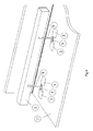
- Figure 4 gives a perspective view of the connection of a number of flexible connection elements to the carcass according to the subject panel.
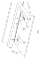
- Figure 5 gives a perspective view of the positioning of seismic connection elements within the panel according to the subject embodiment.
- Figure 6 gives a perspective view of the positioning of rails within the panel according to the subject embodiment.
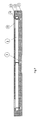
- Figure 7 gives a side view of the final state construction of the panel.
- Figures 2 and 3 illustrate front and top views of the subject panel respectively.
- the configuration providing the flexible connection between and of the panel shell (11) and the carcass comprises a first bar (8) extending substantially horizontally with respect to the figure, and a second bar (9) fastened substantially perpendicularly respect to the first bar (8).
- Said first bar (8) is supported by bearing housings (4) within the pad (3) elements positioned on the inner-upper surface of the shell (11) in a mutual manner so that said bar (8) is enabled to displace in each direction of three-dimensional space.
- the bearing housings (4) in said pads (3) are embodied of a larger size than that of the first bar (8), it is made possible for the first bar (8) to displace a certain distance on the axis of itself, on the axis of the second bar, and on the transversal axis.
- the first bar (8) While the ends of the first bar (8) are supported in the pads (3), the supporting/bearing ends, or the surfaces of pads to provide support/bearing are coated by silicon or any other similarly-functioning material so as to create a spring effect. In this manner, the first bar (8) is provided with freedom of displacement on right- and leftward, up- and downward, and on the transverse directions, i.e. in three dimensions.
- displacement of the first bar'(8) in any dimension can be restricted depending on the manner it is supported, and hence, the free displacement capability of said bar can be reduced to two dimensions only, in case needed.
- the first bar (8) is mounted to a second bar (9) substantially extending vertically with respect to the Figure by means of a bar connection piece (5).
- the second bar (9) is fixed to the carcass (1) by means of a connection piece (2) on a point that is close to the other end of itself (9).
- the fixation of the second bar (9) to the connection piece (5) is preferably performed by means of welding (6).
- the fixation of the second bar (9) to the carcass (1) is carried out preferably by welding (7) to the carcass connection piece (2).
- the weld-joining method is preferred in assembling the first bar (8), the bar connection piece (5), and the second bar (9).
- the configuration e.g. first bar, second bar, connection piece, etc.
- the connected/related parts thereof can be formed so as to be made of any materials
- the materials used are steel.
- first bar (8) and the second bar (9) are formed to have a single-piece parts, in this particular embodiment bar connection piece (5) can be excluded.
- first bar (8) horizontally extending in Figure 2 can be formed so as to include a group of a plurality of bars (2, 3, etc.) in connection with each other.
- second bar (9) vertically extending in Figure 2 can also be formed so as to include a group of a plurality of bars (2, 3, etc.) in connection with each other.
- Figure 4 gives a perspective view of the connection of a number of flexible connection elements in the panel to the carcass according to the present invention.
- the distance between the flexible connection configurations can be adjusted to a value to be predetermined by taking into account the wind loads the panel will be exposed to.
- one more of the subject flexible connection configurations is positioned between the panel shell (11) and the carcass (1) to function as a seismic connection element (10).
- a corresponding representative embodiment is illustrated in Figure 5.
- rails (15) are fixed preferably to four corners of the panel, preferably by means of welding, as shown in Figure 6.
- polystyrene bead concrete (12) is preferably composed of a mixture of polystyrene beads (10-15 kg/m 3 density), cement, and sand. In a preferred embodiment of the present invention, this mixture is formulated so as to have a dry density preferably of 120 to 500 kg/m 3 in line with targeted heat insulation values (0.050 - 0.30 lambda value), and is prepared after being mixed in a concrete mixer.
- the polystyrene beads in the polystyrene bead aggregated concrete (PBAC) filled in the panel shell have closed air pores, the stationary air trapped in such enclosed air pores providing a quite efficient heat insulation.
- these beads are mixed with a type of concrete of proper formulation so that a filling material is obtained, which has a high heat insulation capability and which can respire as the polystyrene beads are bound within/to the concrete. In this manner, the humidity in the air is avoided from permeating to the stationary air gaps within the beads.
- a net (13) having a mesh size preferably of 10 x 10 mm and made from glass fiber that is resistant to alkaline conditions is spread, and it is coated up to the upper level of the shell by means of plaster spraying.
- Said net (13) can alternatively be another type that may be made from plastic material, or Rabitz wire, or from wire mat with relatively larger mesh size.
- the second bar (9), in place of the first bar (8) that extends horizontally with respect to Figure 2, can be supported by the carcass (1) so as to become displaceable in three directions in three-dimensional space in the configuration ensuring the connection between the panel shell (11) and the carcass (1).
- the first bar (9) extending vertically with respect to Figure 2 is supported by the bearing housing embodied on the carcass preferably by the upper section of said bar (9), and since the size of the bearing gap will be embodied relatively larger than the size of the second bar (9) similarly to the structure employed in the preferred embodiment, it becomes possible to have the second bar (9) displace a certain distance along the axis of itself (9), the axis of the first bar, and in the transversal axis.
- both bars are enabled to displace in three dimensions, in addition to supporting only the second bar (9), as indicated above, so that said bar (9) is made displaceable in three dimensions.
- the panel shell (11) and the carcass (1) can be mutually connected also by means of a bar equipped with a spherical joint on both or one of the ends of itself.
- silicon or a similar material can be applied between the spherical joints and the bearings. Thanks to this alternative embodiment, the panel shell (11) is enabled to carry out relative displacement in three directions with respect to the carcass.
Landscapes
- Engineering & Computer Science (AREA)
- Architecture (AREA)
- Chemical & Material Sciences (AREA)
- Ceramic Engineering (AREA)
- Civil Engineering (AREA)
- Structural Engineering (AREA)
- Load-Bearing And Curtain Walls (AREA)
- Finishing Walls (AREA)
- Building Environments (AREA)
Abstract
Description
- The present invention relates to a façade panel connectable to a stud frame arrangement flexibly in a number of directions and reinforced with glass fiber providing heat insulation.
- Façade panel covering systems have been widely applicable due to the significant advantages they provide in avoiding the condensation processes occurring on external skins of buildings and in enhancing the sound and heat insulation efficiency.
- The efficient provision of said advantages is basically related both to the connective constructions between the façade panels and the building aprons, and to the content of panel material. Indeed, any relative mechanical displacements between the panels and aprons due to seismic movements, for instance, negatively affect the proper placement of such panels on aprons. Additionally, in panels accommodating stud frames within themselves, any stress based on thermal expansion between the panel and the stud frame is capable to cause panel cracking (due to stress differences).
- The content of panel material, on the other hand, is selected from those material compositions having a character ensuring adequate heat insulation. While the material composition of panels is chosen, avoiding any substantial weight increase in the panel becomes a significant criterion with respect both to transport convenience, and to preventing any static overweight to occur on the building carcass.
- Many recommendations put into practice considering the aforesaid matters and deemed to provide solutions have been known by the person skilled in the art. Such recommendations are based on panel constructions ensuring a relatively-flexible displacement tolerance between the panel and the stud frame, and composed of relatively light materials providing heat insulation.
- In
US 5,032,340 , for instance, the flexion tolerance against any stress to occur between a glass-fiber-reinforced panel and the stud frame is ensured by means of a flexible bar, of which one end is coupled to those pad connections formed on the panel's shell, and the other end fastened to the carcass. Though the flexible connection disclosed inUS 5,032,340 provides a partial contribution to the purpose of ensuring a flexible displacement between the panel and carcass, the free displacement capability of this flexibility is applicable on a single dimension, and is dependent only on the elasticity character (elasticity coefficient - Young modulus) of said bar's material. In other words, no constructive flexible displaceability is provided between the panel and carcass inUS 5,032,340 . This brings a disadvantage leading to coupling stresses of and between the panel and carcass, particularly when the panel sizes are relatively big. - Another publication of this background art is known from the patent application
TR 97/00100 TR 97/00100 TR 97/00100 US 5,032,340 , and therefore, the disadvantages mentioned above are applicable here as well. - On the other hand, it is known that many heat insulation materials are being used to improve the heat insulation capabilities of façade panels in use, such materials selected among polyurethane foam, styropor board, light aggregated (pumice, glass beads, slag) concrete, rock wool and cellular concrete, e.g.
- Polyurethane foam applications have some drawbacks in that they are expensive, not resistant against fire and in that their thermal expansions is not well tolerated by the panel shell, and have a short economical life since polyurethane becomes deteriorated in time.
- Furthermore, filling with EPS or XPS boards is a difficultly-applicable method because of the intense involvement of flexible connections coupling the panel to the carrier. Such panels have also poor fire resistance.
- Filling with light aggregated concrete (pumice, glass beads, slag) provides an efficient fire resistance, but since the material density in these filling materials are high, the panel becomes heavy, and no adequate heat insulation is ensured because the heat insulation coefficient of such materials are high.
- In filling work employing cellular concrete, there is a drawback in that the thermal conductivity coefficient of this material becomes relatively higher as the material density is generally kept over 400 kg/m3 in practice. In order to provide adequate heat insulation, it becomes necessary to enhance the panel thickness, this case increasing the cost and the weight of panel. Besides, cellular concrete has intensive air pores therein. In theory, the heat insulation is ensured by means of stationary air pores it accommodates. The heat insulation is very low on constant temperature and zero relative humidity conditions. Under atmospheric air conditions, however, both the environmental temperature and the relative humidity rate are continuously altering. Since the vapor diffusion resistance value of the cellular concrete is low, the atmospheric humidity permeates into the air blanks within the concrete's structure. As is a known fact, the water molecules within stationary air accelerate the heat transfer. Therefore the heat conductivity coefficient of cellular concrete is increased and the desired heat insulation cannot be provided.
- One objective of the present invention is to eliminate the potential risk of stress-based (and even crack-based, etc.) panel wastage due to stresses occurring on panel-carcass connections, by providing a flexible connection of façade panels to the stud frame assembly in a multidirectionally displaceable manner.
- Another objective of the present invention is to reduce the weight of façade panels and cost by enhancing heat insulation efficiency of panels.
- In order to achieve these objectives, the present invention provides a panel comprising a panel shell having substantially glass-fiber-reinforced concrete material, a stud frame provided to the panel, and flexible connection means providing the stud frame with flexible displacement with respect to the panel shell when necessary, the subject panel being characterized in that said flexible connection means have a connection configuration allowing the flexible connections to displace in least two dimensions within three-dimensional space.
- In a preferred embodiment according to the present invention, said flexible connection configuration having displacement freedom in three-dimensional space comprises a first bar supported by pad elements fastened to the panel shell and preferably positioned in a mutual fashion, and a second bar fastened substantially perpendicular to said first bar and fixed to the stud frame from one of its ends. Since the bearing of the first bar by the pad elements is ensured by means of silicon or any other similarly-functioning material, it is possible for the first bar, thus the second bar, and therefore the stud frame to perform relative displacement with respect to the horizontal, vertical and in transverse directions.
- In another preferred embodiment of the present invention, the rails on corners, where the panel-to-façade connections are made, are welded to the carcass. Furthermore, the seismic connection elements are fastened to the carcass to provide panel stability against seismic displacements.
- The interior of the panel shell is filled with polystyrene bead concrete composed of a mixture of polystyrene beads, sand, and concrete to ensure the heat insulation of panel.
- The present invention is to be evaluated together with the annexed figures briefly described hereunder to make clear the subject embodiment and the advantages thereof.
- Figure 1 illustrates a prior art embodiment of a panel, stud frame, and flexible connection elements.
- Figure 2 gives a front view of the subject panel.
- Figure 3 gives a top view of the subject panel.
- Figure 4 gives a perspective view of the connection of a number of flexible connection elements to the carcass according to the subject panel.
- Figure 5 gives a perspective view of the positioning of seismic connection elements within the panel according to the subject embodiment.
- Figure 6 gives a perspective view of the positioning of rails within the panel according to the subject embodiment.
- Figure 7 gives a side view of the final state construction of the panel.
-
- 1.
- Carcass
- 2.
- Carcass connection piece
- 3.
- Pad
- 4.
- Bearing housing
- 5.
- Bar connection piece
- 6.
- Connection piece welding
- 7.
- Carcass welding
- 8.
- First bar
- 9.
- Second bar
- 10.
- Seismic connection element
- 11.
- Shell
- 12.
- Polystyrene bead concrete
- 13.
- Net
- 14.
- Plaster
- 15.
- Panel-to-façade connection rail
- Figures 2 and 3, illustrate front and top views of the subject panel respectively. According to these figures, the configuration providing the flexible connection between and of the panel shell (11) and the carcass comprises a first bar (8) extending substantially horizontally with respect to the figure, and a second bar (9) fastened substantially perpendicularly respect to the first bar (8). Said first bar (8) is supported by bearing housings (4) within the pad (3) elements positioned on the inner-upper surface of the shell (11) in a mutual manner so that said bar (8) is enabled to displace in each direction of three-dimensional space. Since the bearing housings (4) in said pads (3) are embodied of a larger size than that of the first bar (8), it is made possible for the first bar (8) to displace a certain distance on the axis of itself, on the axis of the second bar, and on the transversal axis.
- While the ends of the first bar (8) are supported in the pads (3), the supporting/bearing ends, or the surfaces of pads to provide support/bearing are coated by silicon or any other similarly-functioning material so as to create a spring effect. In this manner, the first bar (8) is provided with freedom of displacement on right- and leftward, up- and downward, and on the transverse directions, i.e. in three dimensions.
- In one embodiment of the present invention, displacement of the first bar'(8) in any dimension can be restricted depending on the manner it is supported, and hence, the free displacement capability of said bar can be reduced to two dimensions only, in case needed.
- In another preferred embodiment of the present invention, the first bar (8) is mounted to a second bar (9) substantially extending vertically with respect to the Figure by means of a bar connection piece (5). The second bar (9) is fixed to the carcass (1) by means of a connection piece (2) on a point that is close to the other end of itself (9). The fixation of the second bar (9) to the connection piece (5) is preferably performed by means of welding (6).
- The fixation of the second bar (9) to the carcass (1) is carried out preferably by welding (7) to the carcass connection piece (2). The weld-joining method is preferred in assembling the first bar (8), the bar connection piece (5), and the second bar (9).
- This weld-joining should not be considered as restricting the scope of the present invention, because said parts/pieces can be assembled by means of any other methods known in the art.
- Whereas the configuration (e.g. first bar, second bar, connection piece, etc.) ensuring the flexible displacement according to the present invention, and the connected/related parts thereof can be formed so as to be made of any materials, according to the preferred embodiment of the present invention the materials used are steel.
- In a further preferred embodiment of the present invention, the first bar (8) and the second bar (9) are formed to have a single-piece parts, in this particular embodiment bar connection piece (5) can be excluded.
- Yet in a further embodiment of the present invention, the first bar (8) horizontally extending in Figure 2 can be formed so as to include a group of a plurality of bars (2, 3, etc.) in connection with each other. Similarly, the second bar (9) vertically extending in Figure 2 can also be formed so as to include a group of a plurality of bars (2, 3, etc.) in connection with each other.
- Figure 4 gives a perspective view of the connection of a number of flexible connection elements in the panel to the carcass according to the present invention. The distance between the flexible connection configurations can be adjusted to a value to be predetermined by taking into account the wind loads the panel will be exposed to.
- Particularly for enhancing the panel's stability against seismic movements, preferably one more of the subject flexible connection configurations is positioned between the panel shell (11) and the carcass (1) to function as a seismic connection element (10). A corresponding representative embodiment is illustrated in Figure 5.
- In order to perform the assembly of the subject panel to a building façade, rails (15) are fixed preferably to four corners of the panel, preferably by means of welding, as shown in Figure 6.
- The interior of the subject panel (i.e. the interior of the panel's shell) is filled with polystyrene bead concrete material (12). Polystyrene bead concrete (12) is preferably composed of a mixture of polystyrene beads (10-15 kg/m3 density), cement, and sand. In a preferred embodiment of the present invention, this mixture is formulated so as to have a dry density preferably of 120 to 500 kg/m3 in line with targeted heat insulation values (0.050 - 0.30 lambda value), and is prepared after being mixed in a concrete mixer.
- The polystyrene beads in the polystyrene bead aggregated concrete (PBAC) filled in the panel shell have closed air pores, the stationary air trapped in such enclosed air pores providing a quite efficient heat insulation. By making use of this feature of polystyrene beads, these beads are mixed with a type of concrete of proper formulation so that a filling material is obtained, which has a high heat insulation capability and which can respire as the polystyrene beads are bound within/to the concrete. In this manner, the humidity in the air is avoided from permeating to the stationary air gaps within the beads.
- As seen in Figure 7, after polystyrene bead aggregated concrete (12) is poured into the panel shell (1), a net (13) having a mesh size preferably of 10 x 10 mm and made from glass fiber that is resistant to alkaline conditions is spread, and it is coated up to the upper level of the shell by means of plaster spraying. Said net (13) can alternatively be another type that may be made from plastic material, or Rabitz wire, or from wire mat with relatively larger mesh size. After the façade panel prepared as described above is subjected to the curing process, it is made ready for assembly.
- Regarding an alternative embodiment of the present invention, the second bar (9), in place of the first bar (8) that extends horizontally with respect to Figure 2, can be supported by the carcass (1) so as to become displaceable in three directions in three-dimensional space in the configuration ensuring the connection between the panel shell (11) and the carcass (1). According to this alternative embodiment, the first bar (9) extending vertically with respect to Figure 2 is supported by the bearing housing embodied on the carcass preferably by the upper section of said bar (9), and since the size of the bearing gap will be embodied relatively larger than the size of the second bar (9) similarly to the structure employed in the preferred embodiment, it becomes possible to have the second bar (9) displace a certain distance along the axis of itself (9), the axis of the first bar, and in the transversal axis.
- In the aforesaid alternative embodiment, it is also possible to similarly support both bars so that both bars are enabled to displace in three dimensions, in addition to supporting only the second bar (9), as indicated above, so that said bar (9) is made displaceable in three dimensions.
- In another alternative embodiment of the present invention, the panel shell (11) and the carcass (1) can be mutually connected also by means of a bar equipped with a spherical joint on both or one of the ends of itself. In this embodiment, silicon or a similar material can be applied between the spherical joints and the bearings. Thanks to this alternative embodiment, the panel shell (11) is enabled to carry out relative displacement in three directions with respect to the carcass.
Claims (18)
- A panel comprising a panel shell (11) having substantially glass-fiber-reinforced concrete material, a stud frame (1) provided to the panel, and flexible connection means providing the stud frame (1) with flexible displacement with respect to the panel shell (11) when necessary, characterized in that said flexible connection means has a connection configuration allowing the flexible connections to displace in at least two dimensions within three-dimensional space.
- A panel according to Claim 1, characterized in that said connection configuration comprises a first bar (8) supported by the shell (11), and a second bar (9) connected to said first bar (8) substantially perpendicularly.
- A panel according to anyone of the preceding claims, characterized by comprising preferably two pad (3) elements wherein said first bar (9) is supported.
- A panel according to Claim 3, characterized in that the size of the bearing housings (4) formed in said pad (3) elements is larger than the size of the bars, so that said first bar (8) is enabled to displace in three dimensions.
- A panel according to claims 3 and 4, characterized by comprising silicon or any other similarly-functioning material applied between the supported ends of said first bar (8) and the bearing housings (4).
- A panel according to anyone of the preceding claims, characterized in that said first bar (8) is integrated with said second bar (9), or these two bars (8, 9) are connected by means of a connection piece (5).
- A panel according to anyone of the preceding claims, characterized by comprising a connection piece (2) ensuring the connection of said second bar (9) to said carcass (1).
- A panel according to Claim 1, characterized in that said connection configuration comprises a plurality of first bars (8) supported by said panel shell (11), and one or more than one second bars (9) connected to the plurality of first bars (8).
- A panel according to anyone of the preceding claims, characterized by comprising at least one seismic connection element (10) for enhancing the stability of the panel against seismic movements particularly.
- A panel according to anyone of the preceding claims, characterized by comprising rails (15) to be positioned on the four corners of the panel for assembling the panel to the façade.
- A panel according to anyone of the preceding claims, characterized by comprising polystyrene bead aggregated concrete (12) filled into said panel shell (11) to provide heat insulation.
- A panel according to anyone of the preceding claims, characterized by comprising a net (13) made from glass fiber resistant to alkaline conditions.
- A panel according to anyone of the preceding claims, characterized by comprising plaster (14) applied up to the upper level of the shell.
- A panel according to Claim 1, characterized in that the size of the bearing housings formed to support said second bar (9) by said carcass (1) so as to ensure three-dimensional displacement of the second bar (9) is larger than the bar size of the second bar (9).
- A panel according to Claim 1, characterized in that said connection configuration is a bar which is connected to said shell (11) at one end and connected to said carcass (1) at the other end, the bar having spherical joint/s at one or both ends.
- A panel according to Claim 15, characterized by comprising silicon or any other similarly-functioning material applied between said spherical joints and the housings thereof.
- A panel comprising a panel shell (11) having substantially glass-fiber-reinforced concrete material, a stud frame (1) provided to the panel, and flexible connection means providing the stud frame (1) with flexible displacement with respect to the panel shell (11) when necessary, characterized by having a connection configuration comprising a first bar (8) supported by said shell (11), and a second bar (9) connected to this first bar (8) substantially perpendicularly in order to allow said flexible connection means to displace in at least two directions in three-dimensional space; wherein
preferably two pad (3) elements are provided whereby said first bar (8) is supported, and
the size of bearing housings (4) formed in said pad (3) elements is made larger than the sizes of the bars so that said first bar (8) is enabled to displace in three dimensions. - A panel comprising a panel shell (11) having substantially glass-fiber-reinforced concrete material, a stud frame (1) provided to the panel, and flexible connection means providing the stud frame (1) with flexible displacement with respect to the panel shell (11) when necessary, characterized by comprising polystyrene bead aggregated concrete (12) filled into said shell (11) to provide heat insulation.
Applications Claiming Priority (1)
| Application Number | Priority Date | Filing Date | Title |
|---|---|---|---|
| TR200604278 | 2006-08-10 |
Publications (2)
| Publication Number | Publication Date |
|---|---|
| EP1889984A2 true EP1889984A2 (en) | 2008-02-20 |
| EP1889984A3 EP1889984A3 (en) | 2010-07-21 |
Family
ID=38157924
Family Applications (1)
| Application Number | Title | Priority Date | Filing Date |
|---|---|---|---|
| EP07009980A Withdrawn EP1889984A3 (en) | 2006-08-10 | 2007-05-18 | Facade panel comprising flexible stud frame connection configuration |
Country Status (2)
| Country | Link |
|---|---|
| EP (1) | EP1889984A3 (en) |
| EA (1) | EA012672B1 (en) |
Cited By (2)
| Publication number | Priority date | Publication date | Assignee | Title |
|---|---|---|---|---|
| NL1036484C2 (en) * | 2009-01-29 | 2010-07-30 | Trespa Int Bv | PANEL, METHOD FOR MANUFACTURING A PANEL AND USE FOR A PANEL. |
| ITMI20092187A1 (en) * | 2009-12-15 | 2011-06-16 | Univergom S R L | ANTI-SEISMIC ANCHORAGE BETWEEN PANELS AND STRUCTURE. |
Family Cites Families (7)
| Publication number | Priority date | Publication date | Assignee | Title |
|---|---|---|---|---|
| SU1252444A1 (en) * | 1983-05-06 | 1986-08-23 | Государственный Проектный Институт По Проектированию Предприятий Тяжелой Промышленности | Versions of butt joint of panels of self-supporting walls with skeleton columns |
| US5032340A (en) * | 1987-06-16 | 1991-07-16 | Kajima Corporation | Curtain wall |
| RU2040653C1 (en) * | 1993-01-12 | 1995-07-25 | Виктор Петрович Назаренко | Multi-layer panel and method for making the same |
| TR199700100A2 (en) * | 1997-02-07 | 1998-08-21 | FİBROBETON YAPI ELEMANLARI SAN. İNŞ. ve TİC. LTD. ŞTİ. | Self-insulated prefabricated fiber reinforced concrete (GRC) facade panel and method for its production. |
| RU2114959C1 (en) * | 1997-09-01 | 1998-07-10 | Олег Алексеевич Виноходов | Construction unit |
| RU2158338C1 (en) * | 1999-04-12 | 2000-10-27 | Открытое акционерное общество "Группа Кварц" | Panel and method for its manufacture |
| FI109552B (en) * | 2001-04-26 | 2002-08-30 | Inhan Tehtaat Oy Ab | Hinge has two parts coupled by hinge pin, at least one part being hinge leaf with installation surface and outer surface, installation surface having recess for adjustment plate in leaf cross direction |
-
2007
- 2007-05-18 EP EP07009980A patent/EP1889984A3/en not_active Withdrawn
- 2007-08-02 EA EA200701437A patent/EA012672B1/en not_active IP Right Cessation
Cited By (2)
| Publication number | Priority date | Publication date | Assignee | Title |
|---|---|---|---|---|
| NL1036484C2 (en) * | 2009-01-29 | 2010-07-30 | Trespa Int Bv | PANEL, METHOD FOR MANUFACTURING A PANEL AND USE FOR A PANEL. |
| ITMI20092187A1 (en) * | 2009-12-15 | 2011-06-16 | Univergom S R L | ANTI-SEISMIC ANCHORAGE BETWEEN PANELS AND STRUCTURE. |
Also Published As
| Publication number | Publication date |
|---|---|
| EA200701437A3 (en) | 2008-04-28 |
| EP1889984A3 (en) | 2010-07-21 |
| EA200701437A2 (en) | 2008-02-28 |
| EA012672B1 (en) | 2009-12-30 |
Similar Documents
| Publication | Publication Date | Title |
|---|---|---|
| US4531338A (en) | Building wall panel | |
| EP1889984A2 (en) | Facade panel comprising flexible stud frame connection configuration | |
| CA2284074C (en) | Prefabric fiber reinforced cement (grc) wallpanel | |
| US4691490A (en) | Cementitious modular panel and panel assembly for building walls and method of construction | |
| KR20090114907A (en) | Composite sandwich panel and its manufacturing method | |
| KR101173688B1 (en) | Modular unit system with floor heating plate | |
| RU2145993C1 (en) | Device to encase exterior wall of building for warmth- keeping | |
| JP2011220072A (en) | Earthquake-resistant, heat-insulating and fireproof building | |
| JP3577064B2 (en) | Thermal insulation composite panel for book wall of reinforced concrete construction | |
| KR102101272B1 (en) | Finishing panels for buildings | |
| JP4341977B2 (en) | Outer wall structure in which balcony is projected with cantilever support, method for constructing outer wall, and non-combustible heat insulating block to be used | |
| CN213539478U (en) | Prefabricated wallboard with good heat preservation effect | |
| JP2024125636A (en) | Construction method and structure of refrigerated warehouse | |
| KR20050054901A (en) | The construction method of outer wall insulating with insulation board | |
| JP2020002620A (en) | Insulation structure and building | |
| US20070079565A1 (en) | Light weight sandwich panels | |
| CN222949286U (en) | A fixed installation structure for corner wall decorative curtain wall | |
| JP3577061B2 (en) | Insulation composite panel with earthquake and fire resistance | |
| JPH0533406A (en) | Steel frame vibration isolation fireproof coating method | |
| JP2000297490A (en) | Wall construction method and its wall structure | |
| JP2006183453A (en) | Prism glass panel and its construction method | |
| JP2002061324A (en) | Composite slab construction method, interior backing board used also as form, and fixture therefor | |
| CN219710740U (en) | Building wall and assembled building | |
| CN210263520U (en) | Assembled wall panel | |
| Hegger et al. | Applications for TRC |
Legal Events
| Date | Code | Title | Description |
|---|---|---|---|
| PUAI | Public reference made under article 153(3) epc to a published international application that has entered the european phase |
Free format text: ORIGINAL CODE: 0009012 |
|
| AK | Designated contracting states |
Kind code of ref document: A2 Designated state(s): AT BE BG CH CY CZ DE DK EE ES FI FR GB GR HU IE IS IT LI LT LU LV MC MT NL PL PT RO SE SI SK TR |
|
| AX | Request for extension of the european patent |
Extension state: AL BA HR MK YU |
|
| PUAL | Search report despatched |
Free format text: ORIGINAL CODE: 0009013 |
|
| AK | Designated contracting states |
Kind code of ref document: A3 Designated state(s): AT BE BG CH CY CZ DE DK EE ES FI FR GB GR HU IE IS IT LI LT LU LV MC MT NL PL PT RO SE SI SK TR |
|
| AX | Request for extension of the european patent |
Extension state: AL BA HR MK RS |
|
| RIC1 | Information provided on ipc code assigned before grant |
Ipc: E04B 2/94 20060101ALI20100616BHEP Ipc: E04F 13/14 20060101AFI20070629BHEP |
|
| AKX | Designation fees paid |
Designated state(s): AT BE BG CH CY CZ DE DK EE ES FI FR GB GR HU IE IS IT LI LT LU LV MC MT NL PL PT RO SE SI SK TR |
|
| AXX | Extension fees paid |
Extension state: RS Payment date: 20070518 Extension state: MK Payment date: 20070518 Extension state: HR Payment date: 20070518 Extension state: BA Payment date: 20070518 Extension state: AL Payment date: 20070518 |
|
| STAA | Information on the status of an ep patent application or granted ep patent |
Free format text: STATUS: THE APPLICATION IS DEEMED TO BE WITHDRAWN |
|
| 18D | Application deemed to be withdrawn |
Effective date: 20101201 |