EP1889804A2 - Bobbin wrapping device for wrapping a sheet of material - Google Patents
Bobbin wrapping device for wrapping a sheet of material Download PDFInfo
- Publication number
- EP1889804A2 EP1889804A2 EP07113318A EP07113318A EP1889804A2 EP 1889804 A2 EP1889804 A2 EP 1889804A2 EP 07113318 A EP07113318 A EP 07113318A EP 07113318 A EP07113318 A EP 07113318A EP 1889804 A2 EP1889804 A2 EP 1889804A2
- Authority
- EP
- European Patent Office
- Prior art keywords
- roll
- winding device
- roller
- winding
- web
- Prior art date
- Legal status (The legal status is an assumption and is not a legal conclusion. Google has not performed a legal analysis and makes no representation as to the accuracy of the status listed.)
- Withdrawn
Links
Images

Classifications
-
- B—PERFORMING OPERATIONS; TRANSPORTING
- B65—CONVEYING; PACKING; STORING; HANDLING THIN OR FILAMENTARY MATERIAL
- B65H—HANDLING THIN OR FILAMENTARY MATERIAL, e.g. SHEETS, WEBS, CABLES
- B65H19/00—Changing the web roll
- B65H19/22—Changing the web roll in winding mechanisms or in connection with winding operations
- B65H19/2238—The web roll being driven by a winding mechanism of the nip or tangential drive type
- B65H19/2246—The web roll being driven by a winding mechanism of the nip or tangential drive type and the roll being supported on two rollers
-
- B—PERFORMING OPERATIONS; TRANSPORTING
- B65—CONVEYING; PACKING; STORING; HANDLING THIN OR FILAMENTARY MATERIAL
- B65H—HANDLING THIN OR FILAMENTARY MATERIAL, e.g. SHEETS, WEBS, CABLES
- B65H19/00—Changing the web roll
- B65H19/22—Changing the web roll in winding mechanisms or in connection with winding operations
- B65H19/26—Cutting-off the web running to the wound web roll
- B65H19/265—Cutting-off the web running to the wound web roll using a cutting member moving linearly in a plane parallel to the surface of the web and along a direction crossing the web
-
- B—PERFORMING OPERATIONS; TRANSPORTING
- B65—CONVEYING; PACKING; STORING; HANDLING THIN OR FILAMENTARY MATERIAL
- B65H—HANDLING THIN OR FILAMENTARY MATERIAL, e.g. SHEETS, WEBS, CABLES
- B65H2301/00—Handling processes for sheets or webs
- B65H2301/40—Type of handling process
- B65H2301/41—Winding, unwinding
- B65H2301/414—Winding
- B65H2301/4148—Winding slitting
-
- B—PERFORMING OPERATIONS; TRANSPORTING
- B65—CONVEYING; PACKING; STORING; HANDLING THIN OR FILAMENTARY MATERIAL
- B65H—HANDLING THIN OR FILAMENTARY MATERIAL, e.g. SHEETS, WEBS, CABLES
- B65H2301/00—Handling processes for sheets or webs
- B65H2301/40—Type of handling process
- B65H2301/41—Winding, unwinding
- B65H2301/417—Handling or changing web rolls
- B65H2301/4187—Relative movement of core or web roll in respect of mandrel
- B65H2301/4189—Cutting
- B65H2301/41892—Cutting knife located in winding or guiding roller and protruding therefrom
-
- B—PERFORMING OPERATIONS; TRANSPORTING
- B65—CONVEYING; PACKING; STORING; HANDLING THIN OR FILAMENTARY MATERIAL
- B65H—HANDLING THIN OR FILAMENTARY MATERIAL, e.g. SHEETS, WEBS, CABLES
- B65H2406/00—Means using fluid
- B65H2406/30—Suction means
- B65H2406/33—Rotary suction means, e.g. roller, cylinder or drum
Definitions
- the invention relates to a roll winding device for winding a material web, in particular a paper or board web, on at least one winding tube to at least one winding roll, which is mounted in a winding bed formed by a first and a second axially parallel support roller, wherein the material web over a partial peripheral surface of the first Support roller runs, the roll shell is provided with recesses open against its peripheral surface, and wherein an at least temporarily activatable separation device for web-wide separation of the material web in the region of the partial peripheral surface is provided when producing a new material web start.
- a material web for example in the form of a paper or board web, is produced in a relatively large width of currently up to 12 m and virtually endless.
- the material web In order to be usable for a later consumer, for example a printing company, the material web must be subdivided into narrower webs, so-called material part webs. These narrower webs of material must then be wound into bobbins. For this purpose, a roll winder is used.
- the invention is also applicable to other webs, which also have to be wound into bobbins and handled in a similar manner, such as sheets of cardboard, plastic or metal foil, respectively.
- the material web running over a partial circumferential surface of the support roll is moved by means of a traversing separating knife on the Peripheral surface of the support or support roller separated by machine.
- the support roller is usually provided with recesses open against its circumferential surface, so-called air discharge grooves. These recesses prevent, especially at high grammages, a safe separation of the web. For example, stay at grooved places like bars.
- the material web is held during its separation by means of negative pressure on the peripheral surface of the support roller to thereby reliably supply the material web start the winding tube set for the next roll set to be wound up.
- the negative pressure for the carrier roll punched across its entire roll shell is generated by means of a vacuum fan.
- the achievable negative pressure is reduced such that grammages ⁇ 150 g / m 2 are no longer securely held.
- an excess of false air is caused by causing increased operating costs in the vacuum system.
- the use of a suction zone integrated in the carrier roll is also provided.
- the suction box forming the suction and arranged in the interior of the support roller suction box requires a complex supply and control / regulation system.
- various balancing measures have to be taken so that the reel winders can still be operated efficiently and safely even at higher machine speeds.
- the separating surface viewed in the circumferential direction of the first carrier roll, has a length in the range of 10 to 25 mm, preferably 15 to 20 mm. This length allows an ideal separation of the material web due to the present surface even if the first support roller is not positioned correctly, be it in the forerun or in the caster. In addition, as a result of this length, the material web to be separated sufficiently flat and thus also safely supported.
- the first support roller may be formed as a steel roller. In addition, it can also have an elastomeric cover. In both cases, it may also be provided with recesses open against its peripheral surface.
- the recesses in the area of the continuous web-width parting surface are preferably designed to be discontinuous at least on the feed side. In a further embodiment, they can also be designed to drain on the outlet side. These measures ensure that no air blasts or even air turbulences are generated during normal operation of the reel winder due to suddenly changing contours with air guidance. Overall, the material web can be performed better and quieter over the partial circumferential surface of the first support roller.
- the recesses in the run-up side region of the continuous web-width separating surface can also be acted upon at least in some areas by suction means forming a suction zone. This allows, on the one hand, a fast system evacuation due to a small volume at a sufficiently high volume flow, on the other hand, a sufficiently high pressure for safe supply of the material web start to the core set for the next roll set to be wound up.
- the suction means preferably comprise at least one continuous and axially parallel suction hole in the roll shell, which are connected to preferably radially arranged suction channels, which in turn preferably penetrate the peripheral surface of the first support roller in the region of the recesses.
- suction channels preferably penetrate the peripheral surface of the first support roller in the region of the recesses.
- the suction means further comprise at least one preferably controllable / controllable Suction source, preferably a controllable / controllable vacuum source.
- a controllable / controllable vacuum source preferably a controllable / controllable vacuum source. This can be arranged on the outside, that is, the front side and stationary of the first support roller and can be connected as needed with the other suction means.
- the roll shell is provided on the inside of the at least one continuous and axially parallel suction bore in an ideal manner with at least one balance weight.
- the at least temporarily activatable separating device has, in a preferred embodiment, at least one web-width traversing separating knife. This type of separation is on the one hand, even with material webs with high grammages process reliability, on the other hand, the use of a separating knife as a separating element is inexpensive.
- At least one device for applying at least one adhesive strip to the new material web beginning can additionally be provided.
- This second transfer medium after a successful separation of the material web, further improves the process reliability for transferring the new material web beginning to the winding tube set for the next roll set to be wound up.
- the device for applying at least one adhesive strip to the new material web beginning can be connected to a device for pushing out the wound winding roller from the roller bed to form a unit. This provides the advantage of as few moving components with corresponding movement units.
- At least one blower device acting at least regionally, preferably with a web width can be provided for blowing the new material web start onto the winding tube to be wound be, whereby the process reliability for the transfer of the new material web start to the winding tube set for the next roll-up set to be further improved.
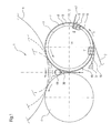
- the roll winding device 1 accordingly has a first axially parallel support roll 3 and a second axially parallel support roll 4, which form a winding bed 5 between them, in which an indicated winding roll 6 is arranged.
- the indicated winding roller 6 is shown here with diameters of different sizes in order to make the progress, ie the diameter increase, visible during winding.
- a supply station from which the material web 2 is withdrawn.
- This element is known per se in a roll winder.
- a plurality of winding rolls 6 can be arranged axially one behind the other in the winding bed 5 in the axial direction of the two support rolls 3, 4.
- the individual bobbins 6 are expediently distributed on both sides of the corresponding roller.
- such a roll winding device 1 is also provided with a longitudinal cutting device which divides the tapered material web 2 into a plurality of partial webs running parallel to one another.
- the partial webs may have a width in the range of about 0.3 to 4.8 m.
- a reel winder such as a back-up roll, also referred to as a rider or load roll, or drive motors for the support rolls 3, 4 are not shown.
- the material web 2 passes over a partial circumferential surface 7 of the first support roller 3, the roll shell 8 has an elastomeric cover 9 and is provided with open towards its peripheral surface 10 recesses 11.
- the recesses 11 are designed as substantially in the circumferential direction R (arrow) of the support roller 3 extending Lucasab thoroughlynuten 12.
- the slitter-winder 1 further has a suction zone 13 integrated in the support roller 3, which is temporarily generated by a suction box 15 arranged in the inner region 14 of the support roller 3.
- a machine-wide cutting support 16 is introduced between the peripheral surface 10 of the support roll 3 and the material web 2 to be separated (position 1). If the introduced cutting pad 16 reaches a certain circumferential position (position II), then the over the partial circumferential surface 7 of the support roller 3 is running Material web 2 by means of an at least temporarily activatable, that is traversing cutting blade 17 on the partial circumferential surface 7 of the support roller 3 when producing a new material web start 18 machine width separated.
- the new material web start 18 can be supplied in a known manner the winding tube set for the next roll set to be wound up, represented by the new winding tube 19.
- the introduced cutting pad 16 must finally be selectively detected again in a merely indicated tray 37.
- FIGS. 2 to 5 show various schematic details of an embodiment of a roll winding device 1 according to the invention.
- this roll winding device 1 corresponds in essential parts to the embodiment of the roll winding device 1 shown and described in FIG. 1, so that reference is made to this.
- FIG. 3 The difference from the embodiment of FIG. 1, which represents the prior art, according to the schematic partial plan view of FIG. 2, is that a continuous web-width separating surface 20 in the effective region W of the first and the winding roll arranged axially parallel to the support roller 3 at least temporarily activatable separating device 21 (see Figure 3) is provided.
- the separating device 21 comprises at least one web-width traversing separating knife 22, which is indicated only symbolically (cf., again, FIG. 3).
- the separation surface 20 has - seen in the circumferential direction R (arrow) of the first support roller 3 - a length L in the range of 10 to 25 mm, preferably from 15 to 20 mm.
- the first support roller 3 has, as shown in the schematic sectional view of Figure 3 according to the section line AA of Figure 2, a steel core 24 and the roll shell 8 forming elastomer cover 9, which is provided with open towards its peripheral surface 10 recesses 11.
- the recesses 11 are designed as grooves 25 and in the circumferential direction R (arrow) the first support roller 3 running inclined (see Figure 2).
- the recesses 11 can also be embodied as blind bores and / or running essentially in the circumferential direction R (arrow) of the first support roller 3.
- the first support roller 3 may be formed as a steel roller with corresponding recesses 11.
- the recesses 11 in the form of mutually parallel grooves 25 are in the region of the continuous web-width separating surface 20 both run-up side (arrow B) and the inlet side (arrow C) running expiring.
- the recesses 11 in the form of mutually parallel grooves 25 in the inlet side region (arrow B) of the continuous web-width separating surface 20 at least partially applied to a suction zone 27 forming suction means 26.
- the suction means 26 comprise in the embodiment shown, three continuous and axially parallel suction holes 28 in the roll shell 8, which are each connected to a radially arranged suction channel 29 (see Figure 4).
- the suction channels 29 in turn penetrate the peripheral surface 10 of the first support roller 3 in the region of the recesses 11.
- the suction means 26 further comprise at least one preferably controllable / controllable suction source 30, preferably a controllable / controllable vacuum source 31, which is not explicitly shown, the expert however, it is known.
- Figure 4 shows a schematic sectional view of the first support roller 3 in the region of the suction means 26.
- the suction means 26 with its three continuous and axially parallel suction holes 28 in the roll shell 8 are arranged such that they provide an optimal version and leadership of the not shown Contribute material web beginning. They are thus arranged upstream side (arrow B) of the mutually parallel grooves 25 of the roll shell 8.
- the roll shell 8 is on the inside of the three continuous and axially parallel suction holes 28 of the suction zone 27 with each provided a balance weight 32.
- the respective balance weight 32 is designed in terms of its geometry and mass distribution such that the missing mass of the associated suction bore 28 is compensated. Of course, the use of only one balance weight on the roll shell 8 may be provided.
- the roll winding device 1 may comprise at least one device 33, not shown, for applying at least one adhesive strip to the new material web beginning, said device 33 being connected in a favorable manner to a device 35 for ejecting the wound winding roll from the roll bed.
- a device 35 is for example in the European patent application EP 1 652 803 A2 set; Their content is hereby made the subject of the present description.
- the unit 35 together with its devices 33, 34 is indicated in FIG. 4 only in an abstract manner.
- the roll winding device 1 may have at least one blowing device 36, which acts at least regionally, preferably in web width and merely indicated, for blowing the new material web beginning 18 against the winding tube 19 to be wound.
- the blowing device 36 is arranged below the winding bed 5 of the roll winding device 1, that is to say between the two support rolls 3, 4 (cf., FIG. 1).
- a roller winding device of the type mentioned above is provided by the invention, with which a process improved, in particular temporally shortened separation of a material web, in particular also a material web can be made with a high grammage.
Abstract
Description
Die Erfindung betrifft eine Rollenwickelvorrichtung zum Aufwickeln einer Materialbahn, insbesondere einer Papier- oder Kartonbahn, auf zumindest eine Wickelhülse zu wenigstens einer Wickelrolle, die in einem von einer ersten und einer zweiten achsparallelen Tragwalze gebildeten Wickelbett gelagert ist, wobei die Materialbahn über eine Teilumfangsfläche der ersten Tragwalze läuft, deren Walzenmantel mit gegen seine Umfangsfläche hin offenen Ausnehmungen versehen ist, und wobei eine zumindest zeitweise aktivierbare Trenneinrichtung zur bahnbreiten Trennung der Materialbahn im Bereich der Teilumfangsfläche bei Herstellung eines neuen Materialbahnanfangs vorgesehen ist.The invention relates to a roll winding device for winding a material web, in particular a paper or board web, on at least one winding tube to at least one winding roll, which is mounted in a winding bed formed by a first and a second axially parallel support roller, wherein the material web over a partial peripheral surface of the first Support roller runs, the roll shell is provided with recesses open against its peripheral surface, and wherein an at least temporarily activatable separation device for web-wide separation of the material web in the region of the partial peripheral surface is provided when producing a new material web start.
Eine Materialbahn, beispielsweise in Form einer Papier- oder Kartonbahn, wird in relativ großer Breite von derzeit bis zu 12 m und quasi endlos hergestellt. Um für einen späteren Verbraucher, beispielsweise eine Druckerei, verwendbar zu sein, muss die Materialbahn in schmalere Bahnen, so genannte Materialteilbahnen, unterteilt werden. Diese schmaleren Materialbahnen müssen dann zu Wickelrollen aufgewickelt werden. Hierzu wird eine Rollenwickelvorrichtung verwendet.A material web, for example in the form of a paper or board web, is produced in a relatively large width of currently up to 12 m and virtually endless. In order to be usable for a later consumer, for example a printing company, the material web must be subdivided into narrower webs, so-called material part webs. These narrower webs of material must then be wound into bobbins. For this purpose, a roll winder is used.
Die Erfindung ist auch bei anderen Materialbahnen, die ebenfalls zu Wickelrollen aufgewickelt und auf ähnliche Weise gehandhabt werden müssen, wie beispielsweise Bahnen aus Karton, Kunststoff- oder Metallfolie, entsprechend anwendbar.The invention is also applicable to other webs, which also have to be wound into bobbins and handled in a similar manner, such as sheets of cardboard, plastic or metal foil, respectively.
Nach dem Fertigwickeln eines Rollensatzes in der Aufrollung einer Rollenwickelvorrichtung wird die über eine Teilumfangsfläche der Tragwalze laufende Materialbahn mittels eines traversierenden Trennmessers auf der Umfangsfläche der Trag- bzw. Stützwalze maschinenbreit getrennt. Die Tragwalze ist gewöhnlich mit gegen ihre Umfangsfläche hin offenen Ausnehmungen, so genannten Luftabführnuten, versehen. Diese Ausnehmungen verhindern, insbesondere bei hohen Grammaturen, ein sicheres Trennen der Materialbahn. Beispielsweise bleiben an genuteten Stellen gerne Stege stehen.After the finish-winding of a set of rolls in the reeling of a reel-winding device, the material web running over a partial circumferential surface of the support roll is moved by means of a traversing separating knife on the Peripheral surface of the support or support roller separated by machine. The support roller is usually provided with recesses open against its circumferential surface, so-called air discharge grooves. These recesses prevent, especially at high grammages, a safe separation of the web. For example, stay at grooved places like bars.
Um dieses Problem zu vermeiden, wird heutzutage eine maschinenbreite Schneidunterlage zwischen der Umfangsfläche der Tragwalze und der zu trennenden Materialbahn eingebracht. Der Trennvorgang erfolgt dann auf der Schneidunterlage, die abschließend wieder gezielt erfasst werden muss.To avoid this problem, nowadays a machine-wide cutting pad is introduced between the peripheral surface of the carrier roll and the material web to be separated. The separation process then takes place on the cutting surface, which finally has to be targeted again.
Weiterhin wird die Materialbahn während ihrer Trennung mittels Unterdruck auf der Umfangsfläche der Tragwalze gehalten, um dadurch den Materialbahnanfang dem Wickelhülsensatz für den nächsten aufzuwickelnden Rollensatz sicher zuzuführen. Der Unterdruck für die über ihren gesamten Walzenmantel hinweg gelochte Tragwalze wird mit einem Unterdruckventilator erzeugt. Da die Materialbahn aber nur einen Teil der gelochten Walze abdeckt, reduziert sich der erzielbare Unterdruck derart, dass Grammaturen ≥ 150 g/m2 nicht mehr sicher gehalten werden. Zudem wird ein Übermaß an Falschluft bei Verursachung erhöhter Betriebskosten in das Unterdrucksystem eingezogen.Furthermore, the material web is held during its separation by means of negative pressure on the peripheral surface of the support roller to thereby reliably supply the material web start the winding tube set for the next roll set to be wound up. The negative pressure for the carrier roll punched across its entire roll shell is generated by means of a vacuum fan. However, since the material web covers only a part of the perforated roller, the achievable negative pressure is reduced such that grammages ≥ 150 g / m 2 are no longer securely held. In addition, an excess of false air is caused by causing increased operating costs in the vacuum system.
Hinsichtlich der verbesserten Sicherung des Materialbahnanfangs wird auch der Einsatz einer in der Tragwalze integrierten Saugzone vorgesehen. Der die Saugzone ausbildende und im Innenbereich der Tragwalze angeordnete Saugkasten benötigt jedoch ein aufwendiges Versorgungs- und Steuerungs-/Regelungssystem. Überdies müssen bei dessen Verwendung verschiedene Wuchtmaßnahmen erfolgen, damit die Rollenwickelmaschinen auch bei höheren Maschinengeschwindigkeiten noch effizient und sicher betrieben werden können.With regard to the improved securing of the material web start, the use of a suction zone integrated in the carrier roll is also provided. However, the suction box forming the suction and arranged in the interior of the support roller suction box requires a complex supply and control / regulation system. Moreover, when using it, various balancing measures have to be taken so that the reel winders can still be operated efficiently and safely even at higher machine speeds.
Es ist die Aufgabe der Erfindung, eine Rollenwickelvorrichtung der eingangs genannten Art bereitzustellen, mit der ein prozessmäßig verbessertes, insbesondere zeitlich verkürztes Trennen einer Materialbahn, insbesondere auch einer Materialbahn mit einer hohen Grammatur erfolgen kann.It is the object of the invention to provide a roll winding device of the type mentioned, with a process improved, in particular temporally shortened separating a material web, in particular also a web can be made with a high grammage.
Diese Aufgabe wird bei einer Rollenwickelvorrichtung der eingangs genannten Art erfindungsgemäß dadurch gelöst, dass eine durchgehende bahnbreite Trennfläche im Wirkbereich der zumindest zeitweise aktivierbaren Trenneinrichtung vorgesehen ist.This object is achieved in a roll winding device of the type mentioned in the present invention, that a continuous web-width separating surface is provided in the effective range of at least temporarily activatable separating device.
Die erfindungsgemäße Aufgabe wird auf diese Weise vollkommen gelöst.The object of the invention is completely solved in this way.
Durch das Vorsehen der durchgehenden bahnbreiten Trennfläche wird selbst eine Materialbahn mit einer hohen Grammatur mit einem Schnitt vollständig getrennt. Die Erzeugung von Stegen an bislang vorhandenen Luftabführnuten kann nicht mehr erfolgen. Die derart ausgebildete Trennfläche erlaubt auch eine wesentlich schnellere Trennung der Materialbahn mit merklich verbesserter Schonung der Trenneinrichtung aufgrund gleichmäßig wirkender Kräfte und Momente. Der Trennprozess der Materialbahn wird hinsichtlich seines Prozesses merklich verbessert.By providing the continuous web-width separating surface even a material web with a high grammage is completely separated with a cut. The generation of webs on previously existing Luftabführnuten can no longer be done. The separating surface formed in this way also permits a significantly faster separation of the material web with noticeably improved protection of the separating device due to uniformly acting forces and moments. The separation process of the web is significantly improved in terms of its process.
In einer ersten bevorzugten Ausführungsform weist die Trennfläche - in Umfangsrichtung der ersten Tragwalze gesehen - eine Länge im Bereich von 10 bis 25 mm, vorzugsweise von 15 bis 20 mm, auf. Diese Länge erlaubt selbst bei nicht exakter Positionierung der ersten Tragwalze, sei sie nun im Vorlauf oder im Nachlauf, noch eine ideale Trennung der Materialbahn aufgrund der vorliegenden Fläche. Zudem wird infolge dieser Länge auch die zu trennende Materialbahn ausreichend flächig und somit auch sicher gestützt.In a first preferred embodiment, the separating surface, viewed in the circumferential direction of the first carrier roll, has a length in the range of 10 to 25 mm, preferably 15 to 20 mm. This length allows an ideal separation of the material web due to the present surface even if the first support roller is not positioned correctly, be it in the forerun or in the caster. In addition, as a result of this length, the material web to be separated sufficiently flat and thus also safely supported.
Die erste Tragwalze kann als eine Stahlwalze ausgebildet sein. Zudem kann sie auch einen Elastomerbezug aufweisen. In beiden Fällen kann sie auch mit gegen ihre Umfangsfläche hin offenen Ausnehmungen versehen sein.The first support roller may be formed as a steel roller. In addition, it can also have an elastomeric cover. In both cases, it may also be provided with recesses open against its peripheral surface.
Damit fortwährend gute bis sehr gute Wickelergebnisse unter anderem auch infolge der Ableitung von Umgebungsluft von der Tragwalzenumfangsfläche erreicht werden können, sind die gegen seine Umfangsfläche hin offenen Ausnehmungen des Walzenmantels in bevorzugter Weise als Blindbohrungen oder als Rillen ausgeführt. Dabei können diese Ausnehmungen als im Wesentlichen in Umfangsrichtung der ersten Tragwalze oder in Umfangsrichtung der ersten Tragwalze geneigt verlaufend ausgeführt sein.This consistently good to very good winding results, among other things, as a result of the discharge of ambient air from the support roller peripheral surface can be achieved, the open towards its peripheral surface recesses of the roll mantle in a preferred manner as blind holes or as grooves. In this case, these recesses may be designed as extending substantially in the circumferential direction of the first support roller or in the circumferential direction of the first support roller inclined.
Weiterhin sind die Ausnehmungen im Bereich der durchgehenden bahnbreiten Trennfläche bevorzugt zumindest auflaufseitig auslaufend ausgeführt. In weitergehender Ausführung können sie auch ablaufseitig auslaufend ausgeführt sein. Diese Maßnahmen stellen sicher, dass keine Luftstöße oder gar Luftturbulenzen während des Normalbetriebs der Rollenwickelmaschine aufgrund sich plötzlich ändernder Konturen mit Luftführung erzeugt werden. Insgesamt kann die Materialbahn besser und ruhiger über die Teilumfangsfläche der ersten Tragwalze geführt werden.Furthermore, the recesses in the area of the continuous web-width parting surface are preferably designed to be discontinuous at least on the feed side. In a further embodiment, they can also be designed to drain on the outlet side. These measures ensure that no air blasts or even air turbulences are generated during normal operation of the reel winder due to suddenly changing contours with air guidance. Overall, the material web can be performed better and quieter over the partial circumferential surface of the first support roller.
Die Ausnehmungen im auflaufseitigen Bereich der durchgehenden bahnbreiten Trennfläche können überdies wenigstens bereichsweise mit eine Saugzone bildenden Saugmitteln beaufschlagt sein. Dies erlaubt einerseits eine schnelle Systemevakuierung aufgrund eines geringen Volumens bei einem ausreichend hohen Volumenstrom, andererseits einen ausreichend hohen Druck zur sicheren Zuführung des Materialbahnanfangs zu dem Wickelhülsensatz für den nächsten aufzuwickelnden Rollensatz.The recesses in the run-up side region of the continuous web-width separating surface can also be acted upon at least in some areas by suction means forming a suction zone. This allows, on the one hand, a fast system evacuation due to a small volume at a sufficiently high volume flow, on the other hand, a sufficiently high pressure for safe supply of the material web start to the core set for the next roll set to be wound up.
Die Saugmittel umfassen bevorzugt wenigstens eine durchgehende und achsparallele Saugbohrung im Walzenmantel, die mit vorzugsweise radial angeordneten Saugkanälen verbunden sind, die wiederum die Umfangsfläche der ersten Tragwalze vorzugsweise im Bereich der Ausnehmungen durchdringen. Somit müssen im Innern der ersten Tragwalze keine Bauteile angeordnet werden. Die Möglichkeit eines Einbaus eines in der ersten Tragwalze integrierten Motors ist also grundsätzlich gegeben.The suction means preferably comprise at least one continuous and axially parallel suction hole in the roll shell, which are connected to preferably radially arranged suction channels, which in turn preferably penetrate the peripheral surface of the first support roller in the region of the recesses. Thus, no components must be arranged in the interior of the first support roller. The possibility of installation of an integrated in the first support roller motor is therefore given in principle.
Ferner umfassen die Saugmittel weiterhin wenigstens eine vorzugsweise steuer-/regelbare Saugquelle, vorzugsweise eine steuer-/regelbare Unterdruckquelle. Diese kann außenseitig, das heißt stirnseitig und stationär der ersten Tragwalze angeordnet sein und bei Bedarf mit den weiteren Saugmitteln verbindbar sein.Furthermore, the suction means further comprise at least one preferably controllable / controllable Suction source, preferably a controllable / controllable vacuum source. This can be arranged on the outside, that is, the front side and stationary of the first support roller and can be connected as needed with the other suction means.
Damit keine Systemunwuchten aufgrund unterschiedlicher Wandeigenschaften entstehen, ist der Walzenmantel innenseitig der wenigstens einen durchgehenden und achsparallelen Saugbohrung in idealer Weise mit mindestens einem Wuchtgewicht versehen. Somit kann die fehlende Masse aufgrund der Saugbohrungen leicht und gerne ausgeglichen werden.So that no system imbalances arise due to different wall properties, the roll shell is provided on the inside of the at least one continuous and axially parallel suction bore in an ideal manner with at least one balance weight. Thus, the missing mass due to the suction holes easily and gladly be compensated.
Die zumindest zeitweise aktivierbare Trenneinrichtung weist in bevorzugter Ausführungsform wenigstens ein bahnbreit traversierendes Trennmesser auf. Diese Art der Trennung ist einerseits selbst bei Materialbahnen mit hohen Grammaturen prozesssicher, andererseits ist die Verwendung eines Trennmessers als Trennelement kostengünstig.The at least temporarily activatable separating device has, in a preferred embodiment, at least one web-width traversing separating knife. This type of separation is on the one hand, even with material webs with high grammages process reliability, on the other hand, the use of a separating knife as a separating element is inexpensive.
In weitergehender Ausführung kann zusätzlich wenigstens eine Einrichtung zum Aufbringen mindestens eines Klebestreifens auf den neuen Materialbahnanfang vorgesehen sein. Dieses zweite Überführmedium verbessert nach einer gelungenen Trennung der Materialbahn weiterhin die Prozesssicherheit für das Überführen des neuen Materialbahnanfangs zu dem Wickelhülsensatz für den nächsten aufzuwickelnden Rollensatz.In a further embodiment, at least one device for applying at least one adhesive strip to the new material web beginning can additionally be provided. This second transfer medium, after a successful separation of the material web, further improves the process reliability for transferring the new material web beginning to the winding tube set for the next roll set to be wound up.
Im Hinblick auf eine mögliche Prozessoptimierung kann die Einrichtung zum Aufbringen mindestens eines Klebestreifens auf den neuen Materialbahnanfang mit einer Einrichtung zum Herausstoßen der bewickelten Wickelrolle aus dem Walzenbett zu einer Einheit verbunden sein. Die erbringt den Vorteil möglichst wenig bewegter Bauteile mit entsprechenden Bewegungseinheiten.With a view to possible process optimization, the device for applying at least one adhesive strip to the new material web beginning can be connected to a device for pushing out the wound winding roller from the roller bed to form a unit. This provides the advantage of as few moving components with corresponding movement units.
Und weiterhin kann als drittes Überführmedium wenigstens eine mindestens bereichsweise, vorzugsweise bahnbreit wirkende Blaseinrichtung zum Anblasen des neuen Materialbahnanfangs an die zu bewickelnde Wickelhülse vorgesehen sein, wodurch die Prozesssicherheit für das Überführen des neuen Materialbahnanfangs zu dem Wickelhülsensatz für den nächsten aufzuwickelnden Rollensatz weitergehend verbessert wird.And furthermore, as the third transfer medium, at least one blower device acting at least regionally, preferably with a web width, can be provided for blowing the new material web start onto the winding tube to be wound be, whereby the process reliability for the transfer of the new material web start to the winding tube set for the next roll-up set to be further improved.
Weitere Merkmale und Vorteile der Erfindung ergeben sich aus der nachfolgenden Beschreibung bevorzugter Ausführungsbeispiele unter Bezugnahme auf die Zeichnung.Further features and advantages of the invention will become apparent from the following description of preferred embodiments with reference to the drawings.
Es zeigen
Figur 1- eine schematische Darstellung einer Rollenwickelvorrichtung gemäß dem Stand der Technik; und
Figuren 2 bis 5- verschiedene schematische Detaildarstellungen einer erfindungsgemäßen Ausführungsform einer Rollenwickelvorrichtung.
- FIG. 1
- a schematic representation of a Rollenwickelvorrichtung according to the prior art; and
- FIGS. 2 to 5
- various schematic representations of an embodiment of a roller winding device according to the invention.
Die Figur 1 zeigt in schematischer Darstellung eine Rollenwickelvorrichtung 1 zum Aufwickeln einer Materialbahn 2, die im vorliegenden Ausführungsbeispiel als Doppeltragwalzen-Wickelmaschine ausgeführt ist. Die Materialbahn 2 kann gegebenenfalls auch eine Materialteilbahn sein. Die Rollenwickelvorrichtung 1 weist dementsprechend eine erste achsparallele Tragwalze 3 und eine zweite achsparallele Tragwalze 4 auf, die zwischen sich ein Wickelbett 5 bilden, in dem eine angedeutete Wickelrolle 6 angeordnet ist. Die angedeutete Wickelrolle 6 ist hier mit unterschiedlich großen Durchmessern dargestellt, um den Fortschritt, also die Durchmesserzunahme, beim Wickeln sichtbar zu machen.1 shows a schematic representation of a
Nicht dargestellt ist eine Vorratsstation, von der die Materialbahn 2 abgezogen wird. Dieses Element ist bei einer Rollenwickelvorrichtung an sich bekannt.Not shown is a supply station, from which the
Abweichend von der Ausgestaltung der Figur 1 kann die nachfolgend erläuterte Idee auch bei einer so genannten Stütz- oder Kontaktwalzen-Wickelmaschine verwendet werden, bei der die Wickelrolle 6 jeweils nur an einer Walze anliegt, im übrigen aber zentrisch gehalten wird.Notwithstanding the embodiment of Figure 1, the idea explained below can also be used in a so-called support or contact roller winding machine, in which the winding
Bei der in der Figur 1 dargestellten Rollenwickelvorrichtung können in Axialrichtung der beiden Tragwalzen 3, 4 gesehen mehrere Wickelrollen 6 axial hintereinander im Wickelbett 5 angeordnet sein. Bei einem Stütz- oder Kontaktwalzenwickler werden zweckmäßigerweise die einzelnen Wickelrollen 6 dann auf beiden Seiten der entsprechenden Walze verteilt.In the case of the roll winding apparatus shown in FIG. 1, a plurality of winding
Üblicherweise ist eine derartige Rollenwickelvorrichtung 1 auch noch mit einer Längsschneideinrichtung versehen, die die zulaufende Materialbahn 2 in mehrere parallel zueinander laufende Teilbahnen unterteilt. Die Teilbahnen können eine Breite im Bereich von etwa 0,3 bis 4,8 m aufweisen.Usually, such a
Nähere Einzelheiten einer Rollenwickelvorrichtung, wie beispielsweise eine Stützwalze, die auch als Reiter- oder Belastungswalze bezeichnet wird, oder Antriebsmotoren für die Tragwalzen 3, 4 sind hier nicht dargestellt.Further details of a reel winder, such as a back-up roll, also referred to as a rider or load roll, or drive motors for the support rolls 3, 4 are not shown.
Die Materialbahn 2 läuft über eine Teilumfangsfläche 7 der ersten Tragwalze 3, deren Walzenmantel 8 einen Elastomerbezug 9 aufweist und mit gegen seine Umfangsfläche 10 hin offenen Ausnehmungen 11 versehen ist. Die Ausnehmungen 11 sind als im Wesentlichen in Umfangsrichtung R (Pfeil) der Tragwalze 3 verlaufende Luftabführnuten 12 ausgeführt.The
Die Rollenschneidmaschine 1 weist weiterhin eine in der Tragwalze 3 integrierte Saugzone 13 auf, die von einem im Innenbereich 14 der Tragwalze 3 angeordneten Saugkasten 15 zeitweise erzeugt wird.The slitter-
Nach dem Fertigwickeln eines Rollensatzes in der Aufrollung einer Rollenwickelvorrichtung 1, dargestellt durch die Wickelrolle 6, wird eine maschinenbreite Schneidunterlage 16 zwischen der Umfangsfläche 10 der Tragwalze 3 und der zu trennenden Materialbahn 2 eingebracht (Position 1). Erreicht die eingebrachte Schneidunterlage 16 eine bestimmte Umfangsposition (Position II), so wird die über die Teilumfangsfläche 7 der Tragwalze 3 laufende Materialbahn 2 mittels eines zumindest zeitweise aktivierbaren, das heißt traversierenden Trennmessers 17 auf der Teilumfangsfläche 7 der Tragwalze 3 bei Herstellung eines neuen Materialbahnanfangs 18 maschinenbreit getrennt. Der neue Materialbahnanfang 18 kann in bekannter Weise dem Wickelhülsensatz für den nächsten aufzuwickelnden Rollensatz, dargestellt durch die neue Wickelhülse 19, zugeführt werden. Die eingebrachte Schneidunterlage 16 muss abschließend in einer lediglich angedeuteten Ablage 37 wieder gezielt erfasst werden.After the finish-winding of a set of rolls in the reeling of a roll-winding
Die Figuren 2 bis 5 zeigen verschiedene schematische Detaildarstellungen einer erfindungsgemäßen Ausführungsform einer Rollenwickelvorrichtung 1.FIGS. 2 to 5 show various schematic details of an embodiment of a
Die Ausgestaltung dieser erfindungsgemäßen Rollenwickelvorrichtung 1 entspricht in wesentlichen Teilen der Ausgestaltung der in der Figur 1 gezeigten und beschriebenen Rollenwickelvorrichtung 1, so dass auf diese verwiesen wird.The configuration of this
Der Unterschied zu der Ausführung der Figur 1, welche den Stand der Technik darstellt, besteht gemäß der schematischen Teildraufsicht der Figur 2 darin, dass an der ersten und zur nicht dargestellten Wickelrolle achsparallel angeordneten Tragwalze 3 eine durchgehende bahnbreite Trennfläche 20 im Wirkbereich W der zumindest zeitweise aktivierbaren Trenneinrichtung 21 (vgl. Figur 3) vorgesehen ist. Die Trenneinrichtung 21 umfasst wenigstens ein bahnbreit traversierendes Trennmesser 22, welches lediglich symbolisch angedeutet ist (vgl. erneut Figur 3).The difference from the embodiment of FIG. 1, which represents the prior art, according to the schematic partial plan view of FIG. 2, is that a continuous web-
Die Trennfläche 20 weist - in Umfangsrichtung R (Pfeil) der ersten Tragwalze 3 gesehen - eine Länge L im Bereich von 10 bis 25 mm, vorzugsweise von 15 bis 20 mm, auf.The
Die erste Tragwalze 3 weist, wie in der schematischen Schnittdarstellung der Figur 3 gemäß der Schnittlinie A-A der Figur 2 dargestellt, einen Stahlkern 24 und einen den Walzenmantel 8 bildenden Elastomerbezug 9 auf, der mit gegen seine Umfangsfläche 10 hin offenen Ausnehmungen 11 versehen ist. Die Ausnehmungen 11 sind als Rillen 25 ausgeführt und in Umfangsrichtung R (Pfeil) der ersten Tragwalze 3 geneigt verlaufend ausgeführt (vgl. Figur 2). Alternativ können die Ausnehmungen 11 auch als Blindbohrungen und/oder im Wesentlichen in Umfangsrichtung R (Pfeil) der ersten Tragwalze 3 verlaufend ausgeführt sein. Grundsätzlich kann die erste Tragwalze 3 als eine Stahlwalze mit entsprechenden Ausnehmungen 11 ausgebildet sein.The
Die Ausnehmungen 11 in Form von zueinander parallelen Rillen 25 sind im Bereich der durchgehenden bahnbreiten Trennfläche 20 sowohl auflaufseitig (Pfeil B) als auch einlaufseitig (Pfeil C) auslaufend ausgeführt.The
Weiterhin sind die Ausnehmungen 11 in Form von zueinander parallelen Rillen 25 im auflaufseitigen Bereich (Pfeil B) der durchgehenden bahnbreiten Trennfläche 20 wenigstens bereichsweise mit eine Saugzone 27 bildenden Saugmitteln 26 beaufschlagt. Die Saugmittel 26 umfassen in der dargelegten Ausführungsform drei durchgehende und achsparallele Saugbohrungen 28 im Walzenmantel 8, die mit jeweils einem radial angeordneten Saugkanal 29 verbunden sind (vgl. Figur 4). Die Saugkanäle 29 wiederum durchdringen die Umfangsfläche 10 der ersten Tragwalze 3 im Bereich der Ausnehmungen 11. Die Saugmittel 26 umfassen weiterhin wenigstens eine vorzugsweise steuer-/regelbare Saugquelle 30, vorzugsweise eine steuer-/regelbare Unterdruckquelle 31, die nicht explizit dargestellt ist, dem Fachmann jedoch bekannt ist.Furthermore, the
Wie bereits dargelegt, zeigt die Figur 4 eine schematische Schnittdarstellung der ersten Tragwalze 3 im Bereich der Saugmittel 26. Die Saugmittel 26 mit ihren drei durchgehenden und achsparallelen Saugbohrungen 28 im Walzenmantel 8 sind derart angeordnet, dass sie zu einer optimalen Fassung und Führung des nicht dargestellten Materialbahnanfangs beitragen. Sie sind also auflaufseitig (Pfeil B) der zueinander parallelen Rillen 25 des Walzenmantels 8 angeordnet.As already explained, Figure 4 shows a schematic sectional view of the
Die Figur 5 zeigt wiederum eine schematische Schnittdarstellung der ersten Tragwalze 3 im Bereich der Saugmittel 26. Der Walzenmantel 8 ist innenseitig der drei durchgehenden und achsparallelen Saugbohrungen 28 der Saugzone 27 mit jeweils einem Wuchtgewicht 32 versehen. Das jeweilige Wuchtgewicht 32 ist hinsichtlich seiner Geometrie und Massenverteilung derart ausgelegt, dass die fehlende Masse der dazugehörigen Saugbohrung 28 ausgeglichen wird. Selbstverständlich kann auch die Verwendung lediglich eines Wuchtgewichts am Walzenmantel 8 vorgesehen sein.5 again shows a schematic sectional view of the
Weiterhin kann die Rollenwickelvorrichtung 1 wenigstens eine nicht dargestellte Einrichtung 33 zum Aufbringen mindestens eines Klebestreifens auf den neuen Materialbahnanfang aufweisen, wobei diese Einrichtung 33 in günstiger Weise mit einer Einrichtung 34 zum Herausstoßen der bewickelten Wickelrolle aus dem Walzenbett zu einer Einheit 35 verbunden ist. Eine derartige Einheit 35 ist beispielsweise in der
Und letztlich kann die Rollenwickelvorrichtung 1 wenigstens eine mindestens bereichsweise, vorzugsweise bahnbreit wirkende und lediglich angedeutete Blaseinrichtung 36 zum Anblasen des neuen Materialbahnanfangs 18 an die zu bewickelnde Wickelhülse 19 aufweisen. Die Blaseinrichtung 36 ist dabei unterhalb des Wickelbetts 5 der Rollenwickelvorrichtung 1, also zwischen den beiden Tragwalzen 3, 4 angeordnet (vgl. Figur 1).And finally, the
Zusammenfassend ist festzuhalten, dass durch die Erfindung eine Rollenwickelvorrichtung der eingangs genannten Art geschaffen wird, mit der ein prozessmäßig verbessertes, insbesondere zeitlich verkürztes Trennen einer Materialbahn, insbesondere auch einer Materialbahn mit einer hohen Grammatur erfolgen kann.In summary, it should be noted that a roller winding device of the type mentioned above is provided by the invention, with which a process improved, in particular temporally shortened separation of a material web, in particular also a material web can be made with a high grammage.
- 11
- RollenwickelvorrichtungReel winding device
- 22
- Materialbahnweb
- 33
- Erste achsparallele TragwalzeFirst axis-parallel support roller
- 44
- Zweite achsparallele TragwalzeSecond axially parallel support roller
- 55
- Wickelbettwinding bed
- 66
- Wickelrollereel
- 77
- TeilumfangsflächePart peripheral surface
- 88th
- Walzenmantelroll shell
- 99
- Elastomerbezugelastomer reference
- 1010
- Umfangsflächeperipheral surface
- 1111
- Ausnehmungrecess
- 1212
- LuftabführnutLuftabführnut
- 1313
- Saugzonesuction zone
- 1414
- Innenbereichinterior
- 1515
- Saugkastensuction box
- 1616
- SchneidunterlageCutting board
- 1717
- Trennmesserseparating knife
- 1818
- MaterialbahnanfangWeb beginning
- 1919
- Wickelhülsemandrel
- 2020
- Trennflächeinterface
- 2121
- Trenneinrichtungseparator
- 2222
- Trennmesserseparating knife
- 2323
- Oberflächesurface
- 2424
- Stahlkernsteel core
- 2525
- Rillegroove
- 2626
- Saugmittelsuction means
- 2727
- Saugzonesuction zone
- 2828
- Saugbohrungsuction bore
- 2929
- Saugkanalsuction
- 3030
- Saugquellesuction source
- 3131
- UnterdruckquelleVacuum source
- 3232
- Wuchtgewichtbalance weight
- 3333
- EinrichtungFacility
- 3434
- EinrichtungFacility
- 3535
- Einheitunit
- 3636
- Blaseinrichtungblower
- 3737
- Ablagefiling
- A-AA-A
- Schnittlinieintersection
- BB
- Pfeilarrow
- CC
- Pfeilarrow
- LL
- Längelength
- II
- Position (Einbringung)Position (contribution)
- IIII
- Position (Trennung)Position (separation)
- RR
- Umfangsrichtung (Pfeil)Circumferential direction (arrow)
- WW
- Wirkbereicheffective range
Claims (16)
dadurch gekennzeichnet,
dass eine durchgehende bahnbreite Trennfläche (20) im Wirkbereich (W) der zumindest zeitweise aktivierbaren Trenneinrichtung (21) vorgesehen ist.Roll winding device (1) for winding a material web (2), in particular a paper or board web, on at least one winding tube (19) to at least one winding roll (6) in one of a first and a second axis-parallel support roll (3, 4). formed winding bed (5) is mounted, wherein the material web (2) over a partial peripheral surface (7) of the first support roller (3) runs, the roll shell (8) against its peripheral surface (10) open towards recesses (11) is provided, and wherein an at least temporarily activatable separating device (21) for web-wide separation of the material web (2) in the region of the partial peripheral surface (7) is provided when producing a new material web start (18),
characterized,
that a continuous web width separating surface (20) in the effective region (W) of at least temporarily activatable separating means (21) is provided.
dadurch gekennzeichnet,
dass die Trennfläche (20) - in Umfangsrichtung (R) der ersten Tragwalze (3) gesehen - eine Länge (L) im Bereich von 10 bis 25 mm, vorzugsweise von 15 bis 20 mm, aufweist.Roll winding device (1) according to claim 1,
characterized,
that the separating surface (20) - in the circumferential direction (R) of the first support roller (3) seen - a length (L) ranging from 10 to 25 mm, preferably from 15 to 20 mm.
dadurch gekennzeichnet,
dass wenigstens die erste Tragwalze (3) als eine Stahlwalze ausgebildet ist, die mit gegen ihre Umfangsfläche (10) hin offenen Ausnehmungen (11, 25) versehen ist.Roll winding device (1) according to claim 1 or 2,
characterized,
in that at least the first carrier roll (3) is designed as a steel roll, which is provided with recesses (11, 25) open towards its circumferential surface (10).
dadurch gekennzeichnet,
dass wenigstens die erste Tragwalze (3) einen den Walzenmantel (8) bildenden Elastomerbezug (9) aufweist, der mit gegen seine Umfangsfläche (10) hin offenen Ausnehmungen (11, 25) versehen ist.Roller winding device (1) according to one of the preceding claims,
characterized,
in that at least the first support roller (3) has an elastomer cover (9) which forms the roll jacket (8) and is provided with recesses (11, 25) which are open towards its peripheral surface (10).
dadurch gekennzeichnet,
dass die Ausnehmungen (11) als Blindbohrungen oder als Rillen (25) ausgeführt sind.Roller winding device (1) according to one of the preceding claims,
characterized,
in that the recesses (11) are designed as blind bores or as grooves (25).
dadurch gekennzeichnet,
dass die Ausnehmungen (11) als im Wesentlichen in Umfangsrichtung (R) der ersten Tragwalze (3) oder in Umfangsrichtung (R) der ersten Tragwalze (3) geneigt verlaufend ausgeführt sind.Roll winding device (1) according to claim 5,
characterized,
in that the recesses (11) are designed to run in an inclined manner substantially in the circumferential direction (R) of the first carrier roller (3) or in the circumferential direction (R) of the first carrier roller (3).
dadurch gekennzeichnet,
dass die Ausnehmungen (11) im Bereich der durchgehenden bahnbreiten Trennfläche (20) zumindest auflaufseitig auslaufend ausgeführt sind.Roller winding device (1) according to one of the preceding claims,
characterized,
that the recesses (11) in the area of the continuous web-width separating surface (20) are designed to run out at least on the feed side.
dadurch gekennzeichnet,
dass die Ausnehmungen (11) im auflaufseitigen Bereich der durchgehenden bahnbreiten Trennfläche (20) wenigstens bereichsweise mit eine Saugzone (27) bildenden Saugmitteln (26) beaufschlagt sind.Roller winding device (1) according to one of the preceding claims,
characterized,
in that the recesses (11) are acted on at least in some areas by suction means (26) forming a suction zone (27) in the area on the upstream side of the continuous web-width separating surface (20).
dadurch gekennzeichnet,
dass die Saugmittel (26) wenigstens eine durchgehende und achsparallele Saugbohrung (28) im Walzenmantel (8) umfassen, die mit vorzugsweise radial angeordneten Saugkanälen (29) verbunden sind, die wiederum die Umfangsfläche (10) der ersten Tragwalze (3) durchdringen.Roll winding device (1) according to claim 8,
characterized,
in that the suction means (26) comprise at least one continuous and axially parallel suction bore (28) in the roll shell (8) which are connected to preferably radially arranged suction channels (29) which in turn penetrate the peripheral surface (10) of the first support roll (3).
dadurch gekennzeichnet,
dass die Saugkanäle (29) die Umfangsfläche (10) der ersten Tragwalze (3) im Bereich der Ausnehmungen (11) durchdringen.Roll winding device (1) according to claim 9,
characterized,
in that the suction channels (29) penetrate the circumferential surface (10) of the first carrier roll (3) in the region of the recesses (11).
dadurch gekennzeichnet,
dass die Saugmittel (26) weiterhin wenigstens eine vorzugsweise steuer-/regelbare Saugquelle (30), vorzugsweise eine steuer-/regelbare Unterdruckquelle (31) umfassen.Roll winding device (1) according to claim 9 or 10,
characterized,
that the suction means (26) further comprise at least one preferably controllable / adjustable suction source (30), preferably a controllable / adjustable vacuum source (31).
dadurch gekennzeichnet,
dass der Walzenmantel (8) innenseitig der wenigstens einen durchgehenden und achsparallelen Saugbohrung (28) mit mindestens einem Wuchtgewicht (32) versehen ist.Roller winding device (1) according to one of claims 9 to 11,
characterized,
that the roll mantle (8) is provided on the inside of at least one continuous and axially parallel suction bore (28) with at least one balancing weight (32).
dadurch gekennzeichnet,
dass die zumindest zeitweise aktivierbare Trenneinrichtung (21) wenigstens ein bahnbreit traversierendes Trennmesser (22) aufweist.Roller winding device (1) according to one of the preceding claims,
characterized,
that the at least temporarily activatable separating means (21) comprises at least one web-wide Traversing separating knife (22).
dadurch gekennzeichnet,
dass wenigstens eine Einrichtung (33) zum Aufbringen mindestens eines Klebestreifens auf den neuen Materialbahnanfang (18) vorgesehen ist.Roller winding device (1) according to one of the preceding claims,
characterized,
in that at least one device (33) for applying at least one adhesive strip to the new material web beginning (18) is provided.
dadurch gekennzeichnet,
dass die Einrichtung (33) zum Aufbringen mindestens eines Klebestreifens auf den neuen Materialbahnanfang (18) mit einer Einrichtung (34) zum Herausstoßen der bewickelten Wickelrolle (6) aus dem Walzenbett (5) zu einer Einheit (35) verbunden ist.Roll winding device (1) according to claim 14,
characterized,
that the device (33) for applying at least one adhesive strip to the new material web start (18) having means (34) for pushing out of the wound reel (6) from the roll bed (5) connected to a unit (35).
dadurch gekennzeichnet,
dass wenigstens eine mindestens bereichsweise, vorzugsweise bahnbreit wirkende Blaseinrichtung (36) zum Anblasen des neuen Materialbahnanfangs (18) an die zu bewickelnde Wickelhülse (19) vorgesehen ist.Roller winding device (1) according to one of the preceding claims,
characterized,
in that at least one blower device (36) acting at least regionally, preferably with a web width, is provided for blowing the new material web beginning (18) against the winding tube (19) to be wound.
Applications Claiming Priority (1)
| Application Number | Priority Date | Filing Date | Title |
|---|---|---|---|
| DE200610038955 DE102006038955A1 (en) | 2006-08-18 | 2006-08-18 | Roll winding device for winding a material web |
Publications (2)
| Publication Number | Publication Date |
|---|---|
| EP1889804A2 true EP1889804A2 (en) | 2008-02-20 |
| EP1889804A3 EP1889804A3 (en) | 2011-11-16 |
Family
ID=38736006
Family Applications (1)
| Application Number | Title | Priority Date | Filing Date |
|---|---|---|---|
| EP07113318A Withdrawn EP1889804A3 (en) | 2006-08-18 | 2007-07-27 | Bobbin wrapping device for wrapping a sheet of material |
Country Status (2)
| Country | Link |
|---|---|
| EP (1) | EP1889804A3 (en) |
| DE (1) | DE102006038955A1 (en) |
Citations (4)
| Publication number | Priority date | Publication date | Assignee | Title |
|---|---|---|---|---|
| GB2050317A (en) * | 1979-05-22 | 1981-01-07 | Jagenberg Werke Ag | Method and apparatus for automatic cutting and winding of webs |
| DE19505870A1 (en) * | 1995-02-21 | 1996-08-22 | Voith Sulzer Papiermasch Gmbh | Winding rollers for paper web roll avoid web bulges, high side forces |
| WO1999006313A1 (en) * | 1997-07-30 | 1999-02-11 | Gottlieb Looser | Winding method, device for separating a tape from the tape winder |
| DE19812723A1 (en) * | 1998-03-24 | 1999-09-30 | Voith Sulzer Papiertech Patent | Reel winding roller with elastic surface on core |
-
2006
- 2006-08-18 DE DE200610038955 patent/DE102006038955A1/en not_active Withdrawn
-
2007
- 2007-07-27 EP EP07113318A patent/EP1889804A3/en not_active Withdrawn
Patent Citations (4)
| Publication number | Priority date | Publication date | Assignee | Title |
|---|---|---|---|---|
| GB2050317A (en) * | 1979-05-22 | 1981-01-07 | Jagenberg Werke Ag | Method and apparatus for automatic cutting and winding of webs |
| DE19505870A1 (en) * | 1995-02-21 | 1996-08-22 | Voith Sulzer Papiermasch Gmbh | Winding rollers for paper web roll avoid web bulges, high side forces |
| WO1999006313A1 (en) * | 1997-07-30 | 1999-02-11 | Gottlieb Looser | Winding method, device for separating a tape from the tape winder |
| DE19812723A1 (en) * | 1998-03-24 | 1999-09-30 | Voith Sulzer Papiertech Patent | Reel winding roller with elastic surface on core |
Also Published As
| Publication number | Publication date |
|---|---|
| DE102006038955A1 (en) | 2008-02-21 |
| EP1889804A3 (en) | 2011-11-16 |
Similar Documents
| Publication | Publication Date | Title |
|---|---|---|
| DE60105027T2 (en) | WINDING SHAFT AND WRAPPER FOR WRAPPING A PAPERWAY | |
| DE2935743A1 (en) | ADDITIONAL DEVICE ON ROLLING DEVICES AND METHOD FOR ROLLING UP PRESSURE-SENSITIVE MATERIALS | |
| EP0792829A2 (en) | Method of and device for winding a paper web into a roll | |
| EP0744365B1 (en) | Method for changing the roll in a winding machine and winding machine for carrying out this method | |
| EP1106554A2 (en) | Movable folding apparatus and folding triangle arrangement | |
| DE102016225980A1 (en) | Device for cutting a material web lug hanging from a material web to be guided through the device, web press and method for producing a product with a web press | |
| DE102019101725A1 (en) | Web overpass when winding | |
| DE102010027820A1 (en) | Method and device for threading a fibrous web in a rewinder | |
| DE4409036A1 (en) | Winding machine for winding strip of paper or cardboard | |
| EP1179630B1 (en) | Method and device for making paper rolls | |
| EP2088106B1 (en) | Coiling machine for winding a web of material | |
| EP1889804A2 (en) | Bobbin wrapping device for wrapping a sheet of material | |
| EP1657194B1 (en) | Reel winding device and method for winding reels | |
| EP1038817A2 (en) | Method and device for leading a web onto a roller | |
| EP1657193B1 (en) | Reel winding device and method for winding reels | |
| DE102010044203B4 (en) | Method for slitting a fibrous web | |
| EP1818298A2 (en) | Method and device for winding partial material webs on cores to partial material web rolls | |
| EP1897831A2 (en) | Method for replacing the roll in a roll winding device and roll winding device for winding a sheet of material | |
| DE60002987T2 (en) | METHOD AND DEVICE FOR REWINDING A PAPER SHEET | |
| EP3962848B1 (en) | Unwinding station | |
| DE19755267C2 (en) | Roll cutter and method for dividing a material web into partial webs | |
| EP2149528A2 (en) | Roll-up device, especially a supported roller roll-up device | |
| EP0957054A1 (en) | Winding machine and method for winding a material web | |
| DE60015144T2 (en) | METHOD FOR CONTINUOUSLY WRAPPING PAPER AND WRAPPER | |
| EP2301871B1 (en) | Method and device for sleeve loading in double carrier-drum winder during operation |
Legal Events
| Date | Code | Title | Description |
|---|---|---|---|
| PUAI | Public reference made under article 153(3) epc to a published international application that has entered the european phase |
Free format text: ORIGINAL CODE: 0009012 |
|
| AK | Designated contracting states |
Kind code of ref document: A2 Designated state(s): AT BE BG CH CY CZ DE DK EE ES FI FR GB GR HU IE IS IT LI LT LU LV MC MT NL PL PT RO SE SI SK TR |
|
| AX | Request for extension of the european patent |
Extension state: AL BA HR MK YU |
|
| PUAL | Search report despatched |
Free format text: ORIGINAL CODE: 0009013 |
|
| AK | Designated contracting states |
Kind code of ref document: A3 Designated state(s): AT BE BG CH CY CZ DE DK EE ES FI FR GB GR HU IE IS IT LI LT LU LV MC MT NL PL PT RO SE SI SK TR |
|
| AX | Request for extension of the european patent |
Extension state: AL BA HR MK RS |
|
| RIC1 | Information provided on ipc code assigned before grant |
Ipc: B65H 19/28 20060101ALI20111013BHEP Ipc: B65H 19/30 20060101ALI20111013BHEP Ipc: B65H 19/26 20060101ALI20111013BHEP Ipc: B65H 18/20 20060101ALI20111013BHEP Ipc: B65H 18/02 20060101ALI20111013BHEP Ipc: B65H 19/22 20060101AFI20111013BHEP |
|
| AKY | No designation fees paid | ||
| REG | Reference to a national code |
Ref country code: DE Ref legal event code: R108 |
|
| REG | Reference to a national code |
Ref country code: DE Ref legal event code: R108 Effective date: 20120725 |
|
| STAA | Information on the status of an ep patent application or granted ep patent |
Free format text: STATUS: THE APPLICATION IS DEEMED TO BE WITHDRAWN |
|
| 18D | Application deemed to be withdrawn |
Effective date: 20120517 |