EP1887752B1 - System und Verfahren zur Verwaltung der Anrufskontinuität in einer IMS-Netzwerkumgebung - Google Patents
System und Verfahren zur Verwaltung der Anrufskontinuität in einer IMS-Netzwerkumgebung Download PDFInfo
- Publication number
- EP1887752B1 EP1887752B1 EP06118838.9A EP06118838A EP1887752B1 EP 1887752 B1 EP1887752 B1 EP 1887752B1 EP 06118838 A EP06118838 A EP 06118838A EP 1887752 B1 EP1887752 B1 EP 1887752B1
- Authority
- EP
- European Patent Office
- Prior art keywords
- call
- imrn
- network node
- message
- recited
- Prior art date
- Legal status (The legal status is an assumption and is not a legal conclusion. Google has not performed a legal analysis and makes no representation as to the accuracy of the status listed.)
- Active
Links
- 238000000034 method Methods 0.000 title claims description 31
- 230000007246 mechanism Effects 0.000 claims description 28
- 230000008569 process Effects 0.000 claims description 13
- 230000011664 signaling Effects 0.000 claims description 8
- 238000012795 verification Methods 0.000 claims description 7
- 230000000977 initiatory effect Effects 0.000 claims description 4
- 241000282836 Camelus dromedarius Species 0.000 claims 1
- 238000004891 communication Methods 0.000 description 15
- 230000006870 function Effects 0.000 description 13
- 238000005516 engineering process Methods 0.000 description 6
- 102000018059 CS domains Human genes 0.000 description 5
- 108050007176 CS domains Proteins 0.000 description 5
- 230000001413 cellular effect Effects 0.000 description 5
- 238000010586 diagram Methods 0.000 description 5
- 238000006243 chemical reaction Methods 0.000 description 4
- 238000013507 mapping Methods 0.000 description 4
- 238000007726 management method Methods 0.000 description 3
- 238000012544 monitoring process Methods 0.000 description 3
- 238000012545 processing Methods 0.000 description 3
- 230000004044 response Effects 0.000 description 3
- 230000003321 amplification Effects 0.000 description 2
- 230000000875 corresponding effect Effects 0.000 description 2
- 238000013500 data storage Methods 0.000 description 2
- 238000013461 design Methods 0.000 description 2
- 238000001914 filtration Methods 0.000 description 2
- 230000001404 mediated effect Effects 0.000 description 2
- 238000010295 mobile communication Methods 0.000 description 2
- 238000012986 modification Methods 0.000 description 2
- 230000004048 modification Effects 0.000 description 2
- 238000003199 nucleic acid amplification method Methods 0.000 description 2
- 238000011330 nucleic acid test Methods 0.000 description 2
- 238000013468 resource allocation Methods 0.000 description 2
- 238000012546 transfer Methods 0.000 description 2
- 230000006978 adaptation Effects 0.000 description 1
- 238000013475 authorization Methods 0.000 description 1
- 230000005540 biological transmission Effects 0.000 description 1
- 238000003490 calendering Methods 0.000 description 1
- 238000004590 computer program Methods 0.000 description 1
- 238000010276 construction Methods 0.000 description 1
- 230000002596 correlated effect Effects 0.000 description 1
- 230000007812 deficiency Effects 0.000 description 1
- 230000001419 dependent effect Effects 0.000 description 1
- 238000001514 detection method Methods 0.000 description 1
- 230000009977 dual effect Effects 0.000 description 1
- 230000002085 persistent effect Effects 0.000 description 1
- 230000000644 propagated effect Effects 0.000 description 1
- 230000002123 temporal effect Effects 0.000 description 1
- 230000007704 transition Effects 0.000 description 1
- 238000010200 validation analysis Methods 0.000 description 1
Images

Classifications
-
- H—ELECTRICITY
- H04—ELECTRIC COMMUNICATION TECHNIQUE
- H04L—TRANSMISSION OF DIGITAL INFORMATION, e.g. TELEGRAPHIC COMMUNICATION
- H04L61/00—Network arrangements, protocols or services for addressing or naming
- H04L61/50—Address allocation
- H04L61/5061—Pools of addresses
-
- H—ELECTRICITY
- H04—ELECTRIC COMMUNICATION TECHNIQUE
- H04L—TRANSMISSION OF DIGITAL INFORMATION, e.g. TELEGRAPHIC COMMUNICATION
- H04L61/00—Network arrangements, protocols or services for addressing or naming
-
- H—ELECTRICITY
- H04—ELECTRIC COMMUNICATION TECHNIQUE
- H04L—TRANSMISSION OF DIGITAL INFORMATION, e.g. TELEGRAPHIC COMMUNICATION
- H04L61/00—Network arrangements, protocols or services for addressing or naming
- H04L61/50—Address allocation
- H04L61/5084—Providing for device mobility
-
- H—ELECTRICITY
- H04—ELECTRIC COMMUNICATION TECHNIQUE
- H04L—TRANSMISSION OF DIGITAL INFORMATION, e.g. TELEGRAPHIC COMMUNICATION
- H04L65/00—Network arrangements, protocols or services for supporting real-time applications in data packet communication
- H04L65/10—Architectures or entities
- H04L65/102—Gateways
- H04L65/1023—Media gateways
- H04L65/103—Media gateways in the network
-
- H—ELECTRICITY
- H04—ELECTRIC COMMUNICATION TECHNIQUE
- H04L—TRANSMISSION OF DIGITAL INFORMATION, e.g. TELEGRAPHIC COMMUNICATION
- H04L65/00—Network arrangements, protocols or services for supporting real-time applications in data packet communication
- H04L65/10—Architectures or entities
- H04L65/102—Gateways
- H04L65/1033—Signalling gateways
- H04L65/104—Signalling gateways in the network
-
- H—ELECTRICITY
- H04—ELECTRIC COMMUNICATION TECHNIQUE
- H04L—TRANSMISSION OF DIGITAL INFORMATION, e.g. TELEGRAPHIC COMMUNICATION
- H04L65/00—Network arrangements, protocols or services for supporting real-time applications in data packet communication
- H04L65/1066—Session management
- H04L65/1083—In-session procedures
- H04L65/1095—Inter-network session transfer or sharing
-
- H—ELECTRICITY
- H04—ELECTRIC COMMUNICATION TECHNIQUE
- H04W—WIRELESS COMMUNICATION NETWORKS
- H04W8/00—Network data management
- H04W8/26—Network addressing or numbering for mobility support
-
- H—ELECTRICITY
- H04—ELECTRIC COMMUNICATION TECHNIQUE
- H04W—WIRELESS COMMUNICATION NETWORKS
- H04W80/00—Wireless network protocols or protocol adaptations to wireless operation
- H04W80/08—Upper layer protocols
- H04W80/10—Upper layer protocols adapted for application session management, e.g. SIP [Session Initiation Protocol]
-
- H—ELECTRICITY
- H04—ELECTRIC COMMUNICATION TECHNIQUE
- H04L—TRANSMISSION OF DIGITAL INFORMATION, e.g. TELEGRAPHIC COMMUNICATION
- H04L65/00—Network arrangements, protocols or services for supporting real-time applications in data packet communication
- H04L65/10—Architectures or entities
- H04L65/1016—IP multimedia subsystem [IMS]
-
- H—ELECTRICITY
- H04—ELECTRIC COMMUNICATION TECHNIQUE
- H04W—WIRELESS COMMUNICATION NETWORKS
- H04W80/00—Wireless network protocols or protocol adaptations to wireless operation
- H04W80/04—Network layer protocols, e.g. mobile IP [Internet Protocol]
Definitions
- the present patent disclosure generally relates to call processing in communications networks. More particularly, and not by way of any limitation, the present patent disclosure is directed to a system and method for managing call continuity in a network environment including a circuit-switched (CS) network and an IP multimedia subsystem (IMS) network.
- CS circuit-switched
- IMS IP multimedia subsystem
- VoIP handover is the process of continuing a voice call as a user moves between IP-based networks (e.g., wireless LAN (WLAN) or Wi-MAX networks, etc.) and circuit-switched cellular networks.
- IP-based networks e.g., wireless LAN (WLAN) or Wi-MAX networks, etc.
- 3GPP 3 rd Generation Partnership Project
- UE dual mode wireless user equipment
- CCCF call continuity control function
- IMS IP multimedia subsystem
- One of the proposed solutions to implement the call routing process involves providing a Public Service Identity in the form of an E.164 number (e.g., a called party number) to which a call reference identity may be appended to generate an IP multimedia routing number (IMRN).
- E.164 number e.g., a called party number
- IMRN IP multimedia routing number
- call reference identity digits are appended to the E.164 number, it results in a number that is longer than the 15-digit length limitation specified under the ITU-T standards. It is therefore possible that the extra digits may be lost when such a number is routed via a network.
- this information may be lost in the international ISDN infrastructure using the ISDN User Part (ISUP) signaling.
- ISUP ISDN User Part
- IMS is designed to support multiple registrations of a common Public Identity from different UE devices, establishing correct call legs becomes paramount in effectuating call continuity.
- 3GPP 3rd Generation Partnership Project
- a mechanism is generally provided for establishing signaling and bearer paths with respect to call origination in a CS network.
- a network node in the IMS creates an IP multimedia routing number (IMRN) by appending call reference digits to the Public Service Identity (PSI) of the node, which is utilized for effectuating call continuity.
- IMRN IP multimedia routing number
- PSI Public Service Identity
- US 2005/0058125 is directed to an arrangement that enables a SIP UE device connected to an IMS domain via IP connectivity to use the CS domain as bearer transport.
- an originating UE device initiates a SIP INVITE method, which includes a number request, whereupon a routing number is provided to the originating UE device.
- the UE device analyzes the received routing number in order to verify whether or not it is possible to encode that number into a suitable information element.
- the present patent disclosure is broadly directed to a scheme for managing call continuity in a network environment including a circuit-switched (CS) network and an IP multimedia subsystem (IMS) network wherein certain unique identity (ID) information supplied by a user equipment (UE) device is utilized.
- the unique ID information may comprise an Instance ID and/or a Globally Routable User Agent Uniform Resource Identifier (GRUU).
- GRUU Globally Routable User Agent Uniform Resource Identifier
- the Instance ID could be IMEI, IMEISV, MIN, ESN, MAC address or any other unique Layer-2 address that could be used to identify the UE device.
- a pool of E.164 numbers are maintained as IP multimedia routing numbers (IMRNs) that can be dynamically allocated for association with at least a portion of the call information received from the UE device.
- the network node associates a select IMRN with at least a portion of the call information in a mapping relationship, wherein the unique ID information corresponds to an ongoing call, and returns it to the UE device.
- the network node utilizes the IMRN mapping to effectuate call continuity with respect to the called party. The IMRN may then be released back to the pool of IMRNs for future use.
- Appropriate timers may be provided at the device and CCCF endpoints so that it can be verified whether a call reference number associated with the call remains valid (e.g., it has not timed out) or the dynamically allocated IMRN remains valid (e.g., it has not timed out).
- the released IMRN may be quarantined for a period of time.
- an embodiment of a method is operable with a UE device in association with a call in an IMS network.
- the claimed embodiment comprises one of more of the following operations: providing call information associated with the call by the UE device to a network node disposed in the IMS network; responsive to receiving a dynamically allocated IMRN from the network node, wherein the dynamically allocated IMRN is mapped to at least a portion of the call information, verifying that a call reference number associated with the call is valid; and upon verification, providing the dynamically allocated IMRN by the UE device to the network node for effectuating call continuity based on a relationship between the dynamically allocated IMRN and the call information.
- a UE device operable to originate a call in an IMS network.
- the claimed embodiment comprises one of more of the following elements: means for providing call information associated with the call to a network node disposed in the IMS network; means, responsive to receiving a dynamically allocated IMRN from the network node, wherein the dynamically allocated IMRN is mapped to at least a portion of the call information, for verifying that a call reference number associated with the call is valid; and means, responsive to the verifying, for providing the dynamically allocated IMRN to the network node for effectuating call continuity based on a relationship between the dynamically allocated IMRN and the call information.
- an IMS network node comprising one or more of the following elements: means for maintaining a pool of IMRNs, wherein a select IMRN is dynamically allocable to at least a portion of call information received from a UE device with respect to a call originated by the UE device; means for associating the select IMRN with a unique ID parameter (i.e., GRW, IMEI, IMEISV, MIN, ESN, MAC address or any other unique Layer-2 address, etc.) received from the UE device and for providing the select IMRN to the UE device; and means for verifying that the select IMRN remains valid when the select IMRN is returned to the network node for effectuating a call continuity process with respect to the call.
- a unique ID parameter i.e., GRW, IMEI, IMEISV, MIN, ESN, MAC address or any other unique Layer-2 address, etc.
- FIG. 1 depicts a network environment including circuit-switched network infrastructure and IM multimedia subsystem (IMS) infrastructure wherein an embodiment of the present patent disclosure may be practiced;
- IMS IM multimedia subsystem
- FIGS. 2A-2C depicts flowcharts associated with one or more exemplary embodiments of the present patent disclosure
- FIGS. 3A and 3B depict message flow diagrams for effectuating call continuity by employing dynamically allocated IP multimedia routing numbers (IMRNs) in accordance with an embodiment
- FIG. 4 depicts a message flow diagram for effectuating call continuity by employing dynamically allocated IMRNs in accordance with another embodiment
- FIGS. 5A and 5B depict message flow diagrams for effectuating call continuity by employing dynamically allocated IMRNs in accordance with a still further embodiment
- FIG. 6 depicts a block diagram of an embodiment of a communications device operable for purposes of the present patent disclosure.
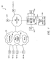
- FIG. 1 an exemplary network environment 100 is depicted wherein an embodiment of the present patent disclosure may be practiced for managing call continuity with respect to a call originated by a UE device.
- the network environment 100 includes an access space 104 comprised of a number of access technologies available to a plurality of UE devices 102-1 through 102-N.
- a UE device may be any tethered or untethered communications device, and may include any personal computer (e.g., desktops, laptops, palmtops, or handheld computing devices) equipped with a suitable wireless modem or a mobile communications device (e.g., cellular phones or data-enabled handheld devices capable of receiving and sending messages, web browsing, et cetera), or any enhanced PDA device or integrated information appliance capable of email, video mail, Internet access, corporate data access, messaging, calendaring and scheduling, information management, and the like.
- the UE device is capable of operating in multiple modes in that it can engage in both circuit-switched (CS) as well as packet-switched (PS) communications, and can transition from one mode of communications to another mode of communications without loss of continuity.
- CS circuit-switched
- PS packet-switched
- the access space 104 may be comprised of both CS and PS networks, which may involve wireless technologies, wireline technologies, broadband access technologies, etc.
- reference numeral 106 refers to wireless technologies such as Global System for Mobile Communications (GSM) networks and Code Division Multiple Access (CDMA) networks, although it is envisaged that the teachings hereof may be extended to any 3 rd Generation Partnership Project (3GPP)-compliant cellular network (e.g., 3GPP or 3GPP2) as well.
- 3GPP 3 rd Generation Partnership Project
- Reference numeral 108 refers to broadband access networks including wireless local area networks or WLANs, Wi-MAX networks as well as fixed networks such as DSL, cable broadband, etc.
- the conventional wireline PSTN infrastructure 110 is also exemplified as part of the access space 104.
- IMS IP multimedia subsystem
- 3GPP 3rd Generation Partnership Project
- IMS IP multimedia subsystem
- IMS IP multimedia subsystem
- IMS IP multimedia subsystem
- IMS is a framework for managing the applications (i.e., services) and networks (i.e., access) that is capable of providing multimedia services.
- IMS defines an "application server" as a network element that delivers services subscribers use, e.g., voice call continuity (VCC), Push-To-Talk (PTT), etc.
- VCC voice call continuity
- PTT Push-To-Talk
- IMS manages applications by defining common control components that each application server (AS) is required to have, e.g., subscriber profiles, IMS mobility, network access, authentication, service authorization, charging and billing, inter-operator functions, and interoperation with the legacy phone network.
- AS application server
- IMS Multimedia Domain
- reference numerals 114-1 to 114-N refer to a plurality of AS nodes operable to support various services, e.g., VCC, PTT, etc., as alluded to hereinabove.
- a VCC AS node 114-N is operable to effectuate call continuity and appropriate domain selection with respect to calls originated by VCC-capable devices.
- AS 114-N may be provided as part of the subscribers' home IMS core network which implements functionality referred to as call continuity control function (CCCF) 116 and network domain selection (NeDS) 118.
- CCCF call continuity control function
- NeDS network domain selection
- the CCCF portion 116 of AS 114-N is operable as a new IMS application server element that resides in the home IMS network and tracks all call sessions and related mobile voice-over-IP (VoIP) bearer traffic, including call handover/routing between CS and IMS domains.
- the NeDS portion 118 of AS 114-N is responsible for performing, inter alia, registration/de-registration management between the IMS and CS networks (e.g., GSM or CDMA).
- GSM Global System for Mobile Communications
- CDMA Code Division Multiple Access
- a suitable session control function (SCF) 120 may be provided as part of the VCC AS node 114-N with respect to applicable radio access technology, e.g., gsmSCF.
- Additional VCC-related functional entities may include the following: Domain Transfer Function (DTF) (also referred to as Functional Entity FE-A), CS Adaptation Function (CSAF) (also referred to as FE-B), CAMEL Service (also referred to as FE-C), and Domain Selection Function (DSF) (also referred to as FE-D), which form a "VCC Application”.
- DTF Domain Transfer Function
- FE-A Functional Entity
- CSAF CS Adaptation Function
- CAMEL Service also referred to as FE-C
- DSF Domain Selection Function
- network node with reference to an IMS core network (such as, e.g., AS 114-N) may comprise one or more of the following functionalities in any combination as applicable: FE-A through FE-D, gsmSCF, CCCF, and NeDS.
- a master user database referred to as a Home Subscriber Server or HSS, is provided as part of the home IMS network 112, for supporting the various IMS network entities that actually manage calls or sessions such as VCC node 114-N.
- HSS Home Subscriber Server
- the HSS database may contain user profiles (i.e., subscription-related information), including various user and device identifies such as International Mobile Subscriber Identity (IMSI), Temporal Mobile Subscriber Identity (TMSI), International Mobile Equipment Identity (IMEI), Mobile Subscriber ISDN Number (MSISDN), as well as additional IMS-specific identities such as IM Multimedia Private Identity (IMPI) and IP Multimedia Public Identity (IMPU) that are implemented as Tel-Uniform Resource Identifiers (URIs) or SIP-URIs.
- IMSI International Mobile Subscriber Identity
- TMSI Temporal Mobile Subscriber Identity
- IMEI International Mobile Equipment Identity
- MSISDN Mobile Subscriber ISDN Number
- IMS-specific identities such as IM Multimedia Private Identity (IMPI) and IP Multimedia Public Identity (IMPU) that are implemented as Tel-Uniform Resource Identifiers (URIs) or SIP-URIs.
- URIs Tel-Uniform Resource Identifiers
- SIP-URIs Tel-Uniform Resource Identifiers
- DB 122 appropriate database structures (e.g., DB 122), timer mechanisms (e.g., timer 124) and suitable logic 126 may be provided in association with AS 114-N for purposes of configuring and managing a pool of IP multimedia routing numbers (IMRNs), also referred to as VCC Directory Numbers or VDNs, from which a select IMRN/VDN may be dynamically allocated for purposes of managing call routing and call continuity as will be described in greater detail below.
- IMRNs IP multimedia routing numbers
- VCC Directory Numbers or VDNs VCC Directory Numbers
- the IMS network node having the CCCF capability is preferably provided with appropriate logic/structure/software/firmware module(s) for performing the following: maintaining a pool of E.164 numbers that are operable as IMRNs which terminate on the network node; dynamically allocating a select IMRN to a called party number and/or certain unique ID information received from a UE device and providing the select IMRN to the originating UE device; verifying that the select IMRN has not timed out when that select IMRN is returned to the network node for effectuating a call routing/continuity process with respect to the called party number; and optionally, quarantining the select IMRN for a period of time upon releasing it back to the IMRN pool for future use.
- the network node may be configured in a number of ways with respect to the E.164 numbers.
- a particular E.164 number may be provided as a "starting address" number of an IMRN range.
- Another E.164 number may operate as a range delimiter with respect to the IMRN range.
- appropriate timer mechanism(s) may be implemented at the network node in order to ensure that the allocated IMRNs remain valid (e.g., they have not timed out, that is, they are used within appropriate time limits) or suitable quarantine times are applied.
- management of timers associated with IMRNs at the network node and timers associated with call reference numbers at the originating UE device allows for dynamic provisioning of IMRNs that could be used for call routing/continuity without having to append extra digits to the E.164 number to create an IMRN.
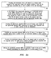
- FIG. 2A depicts a flowchart of an exemplary embodiment of an overall methodology of the present patent disclosure for managing call routing/continuity with respect to a call by a UE device.
- various pieces of information relating to the call (which may be collectively referred to as "call information" herein), such as a call reference number associated with the call, called party number (or, the B number), sub-address information, as well as unique ID information associated with the UE, are provided by the originating UE device to an IMS network node, e.g., AS network node 114-N.
- IMS network node e.g., AS network node 114-N.
- the unique ID information may comprise an Instance Identifier (ID) and/or a GRUU associated with the UE device, wherein the Instance ID may include at least one of an IMEI, an IMEI Software Version (IMEISV), a MAC address or a unique Layer-2 address, an Electronic Serial Number (ESN), and a Mobile Identification Number (MIN) provided with the device.
- ID Instance Identifier
- IMEISV IMEI Software Version
- ESN Electronic Serial Number
- MIN Mobile Identification Number
- a timer may be initiated on the UE device that is used for monitoring at least a portion of the call information. In particular, the timer is implemented for monitoring the elapsed time since a particular call reference number is generated and forwarded to the network node.
- an IMRN selected from the pool of IMRNs is dynamically associated with respect to the call reference number, wherein the IMRN is mapped to the at least a portion of the call information, e.g., the received called party number, or Instance ID and/or GRUU (block 204).
- a timer may be started at the network node for monitoring a time-to-live variable associated with the dynamically allocated IMRN.
- the dynamically allocated IMRN is provided to the UE device using appropriate messaging as will be described below.
- the elapsed time associated with the call reference number is monitored to ensure that it is not stale (block 206).
- the dynamically allocated IMRN is accepted by the UE device if the time elapsed satisfies a select condition, e.g., within a time-to-live value (block 208). Appropriate setup is then initiated by the UE device using the dynamic IMRN, whereby the accepted IMRN is returned to the network node since it terminates on the network node. Upon receipt of the IMRN at the network node, its time-to-live variable is monitored to ensure that it has not timed out. Thereafter, the called party number, GRUU and/or Instance ID (i.e., unique ID data) associated with the dynamically allocated IMRN is utilized for routing the call by making the appropriate connection between the call legs (block 210). In one implementation, the dynamic IMRN may optionally be returned back to the pool of IMRNs wherein it may be quarantined for a certain period of time before it is reused or becomes available for future use (block 212).
- a select condition e.g., within a time
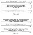
- appropriate logic of the UE device is operable to provide the call information relating to a call to a VCC node such as AS 114-N in FIG. 1 .
- the UE device Responsive to receiving a dynamically allocated IMRN, the UE device is operable to verify that a call reference number associated with the call remains valid (block 224). Upon verification, the UE device thereafter provides the IMRN to the VCC node to set up an outgoing call leg to maintain continuity with an existing call in a different domain (block 226).
- appropriate logic at the node upon receiving the call information including the GRUU and/or Instance ID information, appropriate logic at the node interrogates its databases to perform a number of verifications.
- a verification may be made to determine whether the user is allowed to obtain VCC service.
- Another verification relates to whether the unique ID information received from the UE device exists in the network node's databases, and if so, a dynamic IMRN is allocated and associated with an ongoing call corresponding to the received unique ID information (block 252). Thereafter, the dynamic IMRN is provided to the UE device via suitable messaging (block 254).
- the network node When the dynamic IMRN is returned to the network node as part of the UE's VCC call leg setup, the network node correlates the returned IMRN against the GRUU/Instance ID record created previously in order to link the VCC call leg with respect to the ongoing call (block 256). Also, the network node may include appropriate logic to verify that the received IMRN has not timed out, as set forth hereinabove.
- call information i.e., called party number, call reference number, unique ID information, etc.
- appropriate logic at the network node may create a record that maps the received call information to an E.164-based IMRN, which is transmitted back to the UE device.
- the VCC node can correlate the request to the ongoing dialogue whereupon the dynamic IMRN may be linked to the ongoing call session.
- the UE upon correlating the received IMRN with the call reference number, the UE sets up a call using the IMRN that terminates on the network node. The IMRN is then interrogated against the IMRN/call information mapping for continuing the ongoing call to the called party.
- the message flow between the UE device and the home IMS network's VCC/network node may be mediated through a number of other appropriate network infrastructure elements, and may be implemented in a number of ways depending on the device capabilities as well as the network features and protocols being used.
- the message flow may be mediated via network elements such as a mobile switching center (MSC) and a media gateway control function (MGCF) element disposed between the UE device and its home IMS VCC/network node.
- MSC mobile switching center
- MGCF media gateway control function
- IMS control plane nodes such as Interrogating Call Session Control Function (I-CSCF) nodes and Serving CSCF (S-CSCF) nodes disposed between the MGCF node and the VCC node.
- I-CSCF Interrogating Call Session Control Function
- S-CSCF Serving CSCF
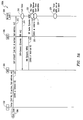
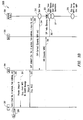
- FIG. 3A depicts a message flow embodiment 300A wherein User-to-User signaling involving Customized Applications for Mobile Enhanced Logic (CAMEL) is implemented.
- exemplary UE device 302 having the CS domain and IMS domain modes of functionality is operable to generate a setup message 310 to a visited MSC 304, wherein the setup message includes applicable call information such as call reference identity or number, called party number, sub-address information, etc. as well as the GRUU and/or Instance ID information.
- a suitable timer mechanism 309 may be initiated at the UE device in order to monitor a time-to-live variable associated with the call reference number.
- MSC 304 Responsive to the setup message 310, MSC 304 generates a CAMEL Application Part (CAP)-compatible message 312, Initial Detection Point (DP) message, which carries at least a portion of the call information to a network node 308 disposed in the user's home IMS network.
- CAP Application Part
- DP Initial Detection Point
- the gsmSCF function of the network node dynamically allocates a select IMRN based on the received called party number and returns it back to MSC 304 via a CAP Connect message 314.
- a suitable timer mechanism may be started (block 316) at the network node 308 in order to monitor a time-to-live variable associated with the dynamically allocated IMRN.
- MSC 304 After verifying that the call reference has not timed out based on the UE device's timer mechanism, responsive to receipt of the CAP Connect message 314, MSC 304 initiates an Initial Address Message (IAM) 318 that includes dynamic IMRN as well as GRUU and/or Instance ID in the User-to-User signaling towards MGCF 306 for call routing.
- IAM Initial Address Message
- a SIP Invite message 320 is generated by MGCF 306 that contains the User-to-User signaling per RFC 3033 towards the network node 308 which then uses the GRUU and/or Instance ID and optionally utilizes the dynamic for continuing the call to the called party (not shown).
- the network node 308 is operable to look up its ongoing calls to see if the GRUU and/or Instance ID can be found. It should be recognized that various intermediate SIP messages and resource allocation/reservation negotiations may take place between MGCF 306 and the called party subsequent to SIP Invite 320, which are not described in particular detail herein. Also, additional ISUP messaging that takes place before a bearer path is established between the UE device 302 and the called party is not shown herein.
- the timer mechanism may be stopped (block 322) to verify if the IMRN has timed out. If so, the SIP Invite message may be discarded and the call routing process may be terminated. If the IMRN has not timed out, the CCCF may set up the call leg using the original called number and link it with the ongoing session based on the unique ID-IMRN correlation. Additionally, if no CallerID (CID) was received in the SIP invite message 320, the network node 308 may insert the CID with appropriate privacy options.
- CID CallerID
- a quarantine timer may be started (block 324) such that the IMRN is prohibited from further use until the quarantine timer is stopped after a period of time (block 326).
- the timer mechanism at the device side may also be used to ensure that the call reference number has not timed out, which reference number is used by the UE device to correlate the information received from the network node (e.g., dynamic IMRN). If the timer expires before the same reference number is received back from the network node, the UE device may reattempt the call process a predetermined number of times (e.g., five attempts), after which if no response has been received, the call procedure may be deemed to have failed. In other words, if the UE device receives a reference number that is no longer valid, it may be discarded and the call procedure may be terminated.
- the network node e.g., dynamic IMRN
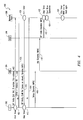
- FIG. 3B Another variation of message flow embodiment 300B is shown in FIG. 3B .
- the message flow embodiment 300B is similar to the embodiment 300A described above, except that additional messaging is provided between UE device 302 and MSC 304 for obtaining the unique ID data.
- a setup message 352 from UE 302 includes various pieces of call information but without the GRUU/Instance ID information.
- a request 354 is generated by MSC 304 towards UE 302 for its unique ID (e.g., Provide IMEI in 3GPP).
- UE 302 provides its unique ID via message 356 to MSC 304, which then generates a CAP-Initial DP message 358 that includes the UE device's unique ID data towards the network node 308.
- the gsmSCF function of the network node 308 uses the unique ID data to determine if there is an ongoing call for the received unique ID. If so, a CAP-Connect message 314 containing a dynamic IMRN is provided by the network node 308 as before. After verifying that the call reference has not timed out based on the UE device's timer mechanism, responsive to receipt of the CAP Connect message 314, MSC 304 initiates an IAM 318 towards MGCF 306 for call routing. A SIP Invite message 362 is generated by MGCF 306 towards the network node 308 which then uses the dynamic IMRN for continuing the call to the called party (not shown). Also, various additional intermediate SIM messages and timer mechanisms may take place similar to the embodiment 300A described above.
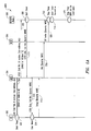
- FIG. 4 depicts a message flow embodiment 400 where a SIP Notify procedure is implemented for messaging. Similar to the CAMEL-based messaging procedure set forth above, UE device 302 having the CS domain and IMS domain modes of functionality is operable to generate a setup message to MSC 304, responsive to which a SIP Notify message 404 may be forwarded directly to the network node 308. As before, the SIP Notify message 404 includes applicable call information such as call reference number, called party number, sub-address information, and the unique ID information. A suitable timer mechanism 402 may be initiated at the UE device in order to monitor a time-to-live variable associated with the call reference number.
- the network node 308 Responsive to the SIP Notify message 404, the network node 308 generates an OK message 406 towards the UE device 302. Thereafter, upon verifying that the user is allowed to do a VCC call, the network node dynamically allocates a select IMRN based on the received call information and returns it back to UE 302 via a SIP Notify message 410. Again, a suitable timer mechanism may be started (block 408) at the network node 308 in order to monitor a time-to-live variable associated with the dynamically allocated IMRN. An OK message 414 is generated by the UE device towards the network node 308 to acknowledge receipt of the SIP Notify message 410.
- a setup message 416 that includes dynamic IMRN is provided by the UE device 302 to MSC 304.
- an IAM message 418 with dynamic IMRN is generated by MSC 304 towards MGCF 306 for effectuating call routing/continuity.
- a SIP Invite message 420 is generated by MGCF 306 towards the network node 308 which utilizes the dynamic IMRN - unique ID mapping for continuing the call to the called party (not shown).
- various intermediate SIP messages and resource allocation/reservation negotiations may take place between MGCF 306 and the called party subsequent to SIP Invite 420, as before. Additional ISUP messaging may also take place before a bearer path is established between the UE device 302 and the called party.
- the timer mechanism may be stopped (block 422) to monitor if the IMRN is still valid. Thereafter, if the IMRN has not timed out, the CCCF may set up the call leg for effectuating call continuity as explained hereinabove. Additional processes such as IMRN release and quarantining, etc. may be effectuated by the network node 308 similar to the processes described above. Appropriate timer mechanisms (blocks 424, 426) may accordingly be implemented at the network node 308. Furthermore, the timer mechanism at the device side may also be used similarly with respect to the call reference number associated with the call.
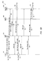
- FIG. 5A depicts a message flow embodiment 500A where Unstructured Supplementary Service Data (USSD) messaging is implemented.
- UE device 302 is operable to generate a USSD message 504 to MSC 404, responsive to which another USSD message 506 may be forwarded to the network node 308.
- the USSD messages 504, 506 include applicable call information such as call reference number, called party number, sub-address information, unique ID information, and the like.
- a suitable timer mechanism 502 may be initiated at the UE device in order to monitor a time-to-live variable associated with the call reference number.
- the network node 308 Responsive to the USSD message 506, the network node 308 generates a USSD message 510 that includes both acknowledgement as well as dynamic IMRN and call reference number information towards MSC 304.
- This USSD message 510 is forwarded to UE 302.
- a suitable timer mechanism may be started (block 508) at the network node 308 in order to monitor a time-to-live variable associated with the dynamically allocated IMRN.
- a setup message 516 After verifying that the call reference has not timed out based on the UE device's timer mechanism (block 514), a setup message 516 that includes dynamic IMRN is provided by the UE device 302 to MSC 304.
- an IAM message 518 with dynamic IMRN is generated by MSC 304 towards MGCF 306 for effectuating call routing/continuity.
- a SIP Invite message 520 is generated by MGCF 306 towards the network node 308 for routing the call to the called party (not shown).
- the timer mechanism may be stopped (block 522) to monitor if the IMRN has timed out. Thereafter, if the IMRN has not timed out, the CCCF may set up the call leg for effectuating call continuity as explained hereinabove. Additionally, processes such as IMRN release and quarantining, etc.
- timer mechanism may be effectuated by the network node 308 similar to the processes described above.
- Appropriate timer mechanisms (blocks 524, 526) may accordingly be implemented at the network node 308.
- the timer mechanism at the device side may also be used similarly with respect to the call reference number associated with the call.
- FIG. 5B Another variation of USSD message flow embodiment 500B is shown in FIG. 5B .
- the message flow embodiment 500B is essentially identical to the embodiment 500A described above, except that separate USSD acknowledgement messages 550 and 556 are propagated between UE 302 and CCCF 308. Accordingly, additional USSD messaging 554 is provided for carrying the IMRN information from CCCF 308 to UE 302.
- the network has the following information: Table II VCC Application UE A UE B IMPI Father Mother Requested-URI Tel URI - Plumber Tel URI - Friend Asserted ID or CLI IMPU Z IMPU Z From IMPU Z IMPU Z To E.164 Number (Plumber E.164 Number (Friend) Contact Header IP address K, Port Y - Behind Home NAT IP address K, Port Z - Behind Home NAT Now consider that Father moves out the house and needs to continue the call using VCC into the cellular network to which he subscribes. This VCC request needs to be correlated to the correct ongoing call session, i.e., UE A's ongoing call rather than UE B's. It will be appreciated that an embodiment of the present disclosure provides the mechanism to advantageously accomplish this process whereby correct call legs are continued as the user maintains the inter-domain call session.
- FIG. 6 depicts a block diagram of an embodiment of a communications device operable as a wireless UE device, e.g., UE 302, for purposes of the present patent disclosure.
- UE 302 may comprise an arrangement similar to one shown in FIG. 6
- a microprocessor 602 providing for the overall control of an embodiment of UE 302 is operably coupled to a communication subsystem 604 that is capable of multi-mode communications (e.g., CS domain, IP domain such as IMS, et cetera).
- the communication subsystem 604 generally includes one or more receivers 608 and one or more transmitters 614 as well as associated components such as one or more local oscillator (LO) modules 610 and a processing module such as a digital signal processor (DSP) 612.
- LO local oscillator
- DSP digital signal processor
- the particular design of the communication module 604 may be dependent upon the communications networks with which the mobile device is intended to operate (e.g., a CDMA network, a GSM network, WLAN, et cetera).
- signals received by antenna 606 through appropriate access infrastructure 605 are provided to receiver 608, which may perform such common receiver functions as signal amplification, frequency down conversion, filtering, channel selection, analog-to-digital (A/D) conversion, and the like.
- signals to be transmitted are processed, including modulation and encoding, for example, by DSP 612, and provided to transmitter 614 for digital-to-analog (D/A) conversion, frequency up conversion, filtering, amplification and transmission over the air-radio interface via antenna 616.
- DSP 612 digital-to-analog
- Microprocessor 602 may also interface with further device subsystems such as auxiliary input/output (I/O) 618, serial port 620, display 622, keyboard/keypad 624, speaker 626, microphone 628, random access memory (RAM) 630, a short-range communications subsystem 632, and any other device subsystems, e.g., timer mechanisms, generally labeled as reference numeral 633.
- I/O auxiliary input/output
- serial port 620 serial port 620
- display 622 keyboard/keypad 624
- speaker 626 speaker 626
- microphone 628 random access memory
- RAM random access memory
- a short-range communications subsystem 632 e.g., timer mechanisms, generally labeled as reference numeral 633.
- SIM/RUIM interface 634 is operable with a SIM/RUIM card having a number of key configurations 644 and other information 646 such as identification and subscriber-related data.
- Operating system software and applicable service logic software may be embodied in a persistent storage module (i.e., non-volatile storage) such as Flash memory 635.
- Flash memory 635 may be segregated into different areas, e.g., storage area for computer programs 636 (e.g., service processing logic), as well as data storage regions such as device state 637, address book 639, other personal information manager (PIM) data 641, and other data storage areas generally labeled as reference numeral 643.
- a transport stack 645 may be provided to effectuate one or more appropriate radio-packet transport protocols.
- a call handover/continuity logic module 408 is provided for effectuating call reference ID generation, validation, verification, and correlation with IMRNs, etc. as set forth hereinabove.
Landscapes
- Engineering & Computer Science (AREA)
- Computer Networks & Wireless Communication (AREA)
- Signal Processing (AREA)
- Multimedia (AREA)
- Databases & Information Systems (AREA)
- Business, Economics & Management (AREA)
- General Business, Economics & Management (AREA)
- Mobile Radio Communication Systems (AREA)
- Telephonic Communication Services (AREA)
- Data Exchanges In Wide-Area Networks (AREA)
- Prostheses (AREA)
Claims (15)
- Ein Verfahren, das mit einer Benutzerausrüstung-UE-Vorrichtung (302) in Assoziation mit einem Anruf in einem Internetprotokoll-IP-Multimedienuntersystem-IMS-Netzwerk (112) betreibbar ist, wobei der Anruf an einen angerufenen Teilnehmer gemacht wird, umfassend:in Reaktion auf ein Erhalten einer E.164 IP-Multimedienroutingnummer, IMRN, die dynamisch von einem Netzwerkknoten (308) zugeordnet wird, wobei die dynamisch zugeordnete IMRN abgebildet wird auf zumindest einen Teil von Anrufinformation, der durch die UE Vorrichtung (302) hinsichtlich des Anrufs bereitgestellt wird, ein Verifizieren, basierend auf einem Zeitnehmermechanismus an der UE-Vorrichtung, dass eine Anrufreferenznummer, die mit dem Anruf assoziiert ist, gültig geblieben ist; undbei Verifizierung ein Bereitstellen der dynamisch zugeordneten IMRN durch die UE-Vorrichtung (302) an den Netzwerkknoten (308), um Anrufkontinuität basierend auf einer Beziehung zwischen der dynamisch zugeordneten IMRN und des Teils der Anrufinformation zu bewirken.
- Das Verfahren nach Anspruch 1, wobei die Anrufinformation zumindest einen aus einem eindeutigen Identitäts-ID-Parameter, der mit der UE-Vorrichtung (302) assoziiert ist, und der angerufenen Teilnehmernummer aufweist.
- Das Verfahren nach Anspruch 2, wobei der eindeutige ID-Parameter zumindest einen aus einem globalroutbaren Benutzeragenten-UA-einheitlichen-Ressourcenidentifikator-URI, GRUU, einer internationalen Mobilstationausrüstungsidentität, IMEI, einer IMEI-Softwareversion, IMEISV, einer elektronischen Seriennummer, ESN, einer mobilen Identifikationsnummer, MIN und einer eindeutigen Layer-2 Adresse, die mit der UE-Vorrichtung (302) assoziiert ist, umfasst.
- Das Verfahren nach Anspruch 1, wobei die Anrufinformation an den Netzwerkknoten (308) mittels einem aus einer Benutzer-zu-Benutzer Signalnachricht, einer Sitzungsinitiierungsprotokoll-SIP-Nachricht und einer unstrukturierten Zusatzdienstdaten-USSD-Nachricht bereitgestellt wird.
- Das Verfahren nach Anspruch 1, wobei die dynamisch zugeordnete IMRN durch die UE-Vorrichtung (302) mittels einer aus einer SIP-Nachricht und einer USSD-Nachricht erhalten wird.
- Das Verfahren nach Anspruch 1, Anspruch 2, Anspruch 3, Anspruch 4 oder Anspruch 5, wobei der Netzwerknoten (308) einen aus einem CCCF-Knoten und einer VCC-Anwendung umfasst.
- Eine Benutzerausrüstung-UE-Vorrichtung (302), die betreibbar ist, um einen Anruf in einem Internetprotokoll-IP-Multimedienuntersystem-IMS-Netzwerk (112) zu machen, wobei der Anruf an einen angerufenen Teilnehmer gerichtet wird, wobei die UE-Vorrichtung (302) umfasst:Mittel (633, 648), die reagieren auf ein Erhalten einer E.164 IP-Multimedienroutingnummer, IMRN, die dynamisch von einem Netzwerkknoten (308) zugeordnet wird, wobei die dynamisch zugeordnete IMRN abgebildet wird auf zumindest einen Teil von Anrufinformation, der durch die UE-Vorrichtung (302) hinsichtlich des Anrufs bereitgestellt wird, um zu verifizieren, dass basierend auf einem Zeitnehmermechanismus an der UE-Vorrichtung (302) eine Anrufreferenznummer, die mit dem Anruf assoziiert ist, gültig geblieben ist; undMittel (602, 604, 648), die auf die Verifizierung reagieren, zum Bereitstellen der dynamisch zugeordneten IMRN an den Netzwerkknoten (302), um Anrufkontinuität basierend auf einer Beziehung zwischen der dynamisch zugeordneten IMRN und des Teils der Anrufinformation zu bewirken.
- Die UE-Vorrichtung (302) nach Anspruch 7, wobei die Anrufinformation zumindest einen aus einem eindeutigen Identitäts-ID-Parameter, der mit der UE-Vorrichtung (302) assoziiert ist, und der angerufenen Teilnehmernummer aufweist.
- Die UE-Vorrichtung (302) nach Anspruch 8, wobei der eindeutige ID-Parameter zumindest einen aus einem globalroutbaren Benutzeragenten-UA-einheitlichen-Ressourcenidentifikator-URI, GRUU, einer internationalen Mobilstationausrüstungsidentität, IMEI, einer IMEI-Softwareversion, IMEISV, einer elektronischen Seriennummer, ESN, einer mobilen Identifikationsnummer, MIN, und einer eindeutigen Layer-2 Adresse, die mit der UE-Vorrichtung (302) assoziiert ist, umfasst.
- Die UE Vorrichtung (302) nach Anspruch 7, wobei die Anrufinformation an
den Netzwerkknoten (302) mittels einem aus einer Benutzer-zu-Benutzer Signalnachricht, einer Sitzungsinitiierungsprotokoll-SIP-Nachricht und einer unstrukturierten Zusatzdienstdaten-USSD-Nachricht bereitgestellt wird. - Die UE-Vorrichtung (302) nach Anspruch 7, Anspruch 8, Anspruch 9 oder
Anspruch 10, wobei die dynamisch zugeordnete IMRN durch die UE-Vorrichtung (302) mittels einer aus einer SIP-Nachricht und einer USSD-Nachricht erhalten wird. - Ein Netzwerkknoten (308), der in einem Internetprotokoll-IP-Multimedienuntersystem-IMS-Netzwerk (112) betreibbar ist, wobei der Netzwerknoten (308) umfasst:Mittel (122, 126), um einen Fundus von E.164 IP-Multimedienroutingnummern IMRNs aufrechtzuerhalten, wobei eine ausgewählte IMRN dynamisch zuordenbar ist zu zumindest einem Teil von Anrufinformation, der von einer Benutzerausrüstung-UE-Vorrichtung (302) hinsichtlich eines Anrufs erhalten wurde, der von der UE-Vorrichtung (302) gemacht wurde;Mittel (126), um die ausgewählte IMRN mit einem eindeutigen Identitäts-ID-Parameter zu assoziieren, der von der UE-Vorrichtung (302) hinsichtlich des Anrufs erhalten wurde, und zum Bereitstellen der ausgewählten IMRN an die UE-Vorrichtung (302); undMittel (124, 126) zum Verifizieren, dass die ausgewählte IMRN gültig bleibt, basierend auf einem Zeitnehmermechanismus an dem Netzwerkknoten, wenn die ausgewählte IMRN an den Netzwerkknoten (308) zurückgegeben wird durch die UE-Vorrichtung zum Bewirken eines Anrufkontinuitätsprozesses hinsichtlich des Anrufs.
- Der Netzwerknoten (308) nach Anspruch 12, wobei die ausgewählte IMRN an die UE-Vorrichtung (302) bereitgestellt wird unter Benutzung einer aus einer Sitzungsinitiierungsprotokoll-SIP-Nachricht und einer unstrukturierten Zusatzdienstdaten-USSD-Nachricht.
- Der Netzwerknoten (308) nach Anspruch 12, der ferner Mittel zum
Erhalten des eindeutigen ID-Parameters erhält, mittels einer aus einer angepassten-Anwendungen-für-mobile-Verbesserungslogik-CAMEL-Anwendungsteil-CAP-Nachricht, einer USSD-Nachricht und eines Mechanismus, der konform ist mit RFC 3033. - Der Netzwerknoten (308) nach Anspruch 12, Anspruch 13 oder Anspruch 14, der ferner Mittel (124, 126) zum Isolieren der ausgewählten IMRN bei deren Freisetzung in den Fundus von IMRNs für eine zukünftige Benutzung aufweist.
Priority Applications (12)
| Application Number | Priority Date | Filing Date | Title |
|---|---|---|---|
| EP14179924.7A EP2802121B1 (de) | 2006-08-11 | 2006-08-11 | System und Verfahren zur Verwaltung der Anrufskontinuität in einer IMS-Netzwerkumgebung |
| EP06118838.9A EP1887752B1 (de) | 2006-08-11 | 2006-08-11 | System und Verfahren zur Verwaltung der Anrufskontinuität in einer IMS-Netzwerkumgebung |
| CN200710152676.2A CN101141812B (zh) | 2006-08-11 | 2007-08-08 | Ims网络环境中管理呼叫连续性的系统和方法 |
| AU2007205728A AU2007205728B2 (en) | 2006-08-11 | 2007-08-09 | System and method for managing call continuity in IMS network environment |
| JP2007210025A JP4762956B2 (ja) | 2006-08-11 | 2007-08-10 | Imsネットワーク環境におけるコール連続性を管理するためのシステムおよび方法 |
| SG200705856-3A SG139728A1 (en) | 2006-08-11 | 2007-08-10 | System and method for managing call continuity in ims network environment |
| MX2007009711A MX2007009711A (es) | 2006-08-11 | 2007-08-10 | Sistema y metodo para manejar continuidad de llamada en ambiente de red de ims. |
| TW096129747A TWI359599B (en) | 2006-08-11 | 2007-08-10 | System and method for managing call continuity in |
| CA2596774A CA2596774C (en) | 2006-08-11 | 2007-08-10 | System and method for managing call continuity in ims network environment |
| SG201000929-8A SG159544A1 (en) | 2006-08-11 | 2007-08-10 | System and method for managing call continuity in ims network environment |
| KR1020070080550A KR100950006B1 (ko) | 2006-08-11 | 2007-08-10 | Ims 네트워크 환경의 콜 연속성 관리 시스템 및 방법 |
| HK08106924.0A HK1112126A1 (en) | 2006-08-11 | 2008-06-23 | System and method for managing call continuity in ims network environment ims |
Applications Claiming Priority (1)
| Application Number | Priority Date | Filing Date | Title |
|---|---|---|---|
| EP06118838.9A EP1887752B1 (de) | 2006-08-11 | 2006-08-11 | System und Verfahren zur Verwaltung der Anrufskontinuität in einer IMS-Netzwerkumgebung |
Related Child Applications (2)
| Application Number | Title | Priority Date | Filing Date |
|---|---|---|---|
| EP14179924.7A Division-Into EP2802121B1 (de) | 2006-08-11 | 2006-08-11 | System und Verfahren zur Verwaltung der Anrufskontinuität in einer IMS-Netzwerkumgebung |
| EP14179924.7A Division EP2802121B1 (de) | 2006-08-11 | 2006-08-11 | System und Verfahren zur Verwaltung der Anrufskontinuität in einer IMS-Netzwerkumgebung |
Publications (2)
| Publication Number | Publication Date |
|---|---|
| EP1887752A1 EP1887752A1 (de) | 2008-02-13 |
| EP1887752B1 true EP1887752B1 (de) | 2015-02-25 |
Family
ID=37648379
Family Applications (2)
| Application Number | Title | Priority Date | Filing Date |
|---|---|---|---|
| EP14179924.7A Active EP2802121B1 (de) | 2006-08-11 | 2006-08-11 | System und Verfahren zur Verwaltung der Anrufskontinuität in einer IMS-Netzwerkumgebung |
| EP06118838.9A Active EP1887752B1 (de) | 2006-08-11 | 2006-08-11 | System und Verfahren zur Verwaltung der Anrufskontinuität in einer IMS-Netzwerkumgebung |
Family Applications Before (1)
| Application Number | Title | Priority Date | Filing Date |
|---|---|---|---|
| EP14179924.7A Active EP2802121B1 (de) | 2006-08-11 | 2006-08-11 | System und Verfahren zur Verwaltung der Anrufskontinuität in einer IMS-Netzwerkumgebung |
Country Status (10)
| Country | Link |
|---|---|
| EP (2) | EP2802121B1 (de) |
| JP (1) | JP4762956B2 (de) |
| KR (1) | KR100950006B1 (de) |
| CN (1) | CN101141812B (de) |
| AU (1) | AU2007205728B2 (de) |
| CA (1) | CA2596774C (de) |
| HK (1) | HK1112126A1 (de) |
| MX (1) | MX2007009711A (de) |
| SG (2) | SG139728A1 (de) |
| TW (1) | TWI359599B (de) |
Families Citing this family (6)
| Publication number | Priority date | Publication date | Assignee | Title |
|---|---|---|---|---|
| DE602006006018D1 (de) * | 2006-01-10 | 2009-05-14 | Research In Motion Ltd | Verfahren und System zur Verwaltung der Rufweiterleitung in einer Netzwerkumgebung umfassend ein leitungsvermittelndes Netzwerk und ein IP Multimedia Subsystem IMS |
| CN101527891B (zh) | 2008-04-30 | 2011-04-20 | 华为技术有限公司 | 一种跨网络呼叫保持方法和设备 |
| CN101610503A (zh) * | 2008-06-20 | 2009-12-23 | 华为技术有限公司 | 一种呼叫建立方法及装置 |
| KR101467392B1 (ko) * | 2008-08-18 | 2014-12-01 | 에스케이텔레콤 주식회사 | 회선교환망과 패킷교환망을 이용한 음성호 통화에 대한 과금 시스템 및 과금 방법 |
| CN102165751B (zh) * | 2008-09-29 | 2014-05-28 | 诺基亚公司 | 隐藏设备身份 |
| KR101659412B1 (ko) * | 2010-06-30 | 2016-09-23 | 주식회사 케이티 | 핸드오버하는 단말기에 선불 서비스를 제공하는 방법 및 장치 |
Family Cites Families (7)
| Publication number | Priority date | Publication date | Assignee | Title |
|---|---|---|---|---|
| US7898990B2 (en) | 2003-03-25 | 2011-03-01 | Spyder Navigations L.L.C. | Method, system and gateway device for enabling interworking between IP and CS networks |
| JP3924554B2 (ja) * | 2003-07-03 | 2007-06-06 | 松下電器産業株式会社 | ハンドオーバ方法およびゲートウェイ装置 |
| US7885208B2 (en) | 2003-09-11 | 2011-02-08 | Nokia Corporation | IP-based services for circuit-switched networks |
| US7359373B2 (en) * | 2003-10-17 | 2008-04-15 | Nokia Corporation | System, apparatus, and method for establishing circuit-switched communications via packet-switched network signaling |
| KR100957327B1 (ko) * | 2004-02-02 | 2010-05-12 | 삼성전자주식회사 | 이종 이동통신 시스템 사이에서 아이피 멀티미디어 서브시스템을 이용한 음성 호 처리 방법 |
| US8694008B2 (en) * | 2005-06-16 | 2014-04-08 | At&T Mobility Ii Llc | Multi-mode handset services |
| DE602006006018D1 (de) * | 2006-01-10 | 2009-05-14 | Research In Motion Ltd | Verfahren und System zur Verwaltung der Rufweiterleitung in einer Netzwerkumgebung umfassend ein leitungsvermittelndes Netzwerk und ein IP Multimedia Subsystem IMS |
-
2006
- 2006-08-11 EP EP14179924.7A patent/EP2802121B1/de active Active
- 2006-08-11 EP EP06118838.9A patent/EP1887752B1/de active Active
-
2007
- 2007-08-08 CN CN200710152676.2A patent/CN101141812B/zh active Active
- 2007-08-09 AU AU2007205728A patent/AU2007205728B2/en active Active
- 2007-08-10 KR KR1020070080550A patent/KR100950006B1/ko active IP Right Grant
- 2007-08-10 SG SG200705856-3A patent/SG139728A1/en unknown
- 2007-08-10 JP JP2007210025A patent/JP4762956B2/ja active Active
- 2007-08-10 MX MX2007009711A patent/MX2007009711A/es active IP Right Grant
- 2007-08-10 TW TW096129747A patent/TWI359599B/zh active
- 2007-08-10 SG SG201000929-8A patent/SG159544A1/en unknown
- 2007-08-10 CA CA2596774A patent/CA2596774C/en active Active
-
2008
- 2008-06-23 HK HK08106924.0A patent/HK1112126A1/xx unknown
Also Published As
| Publication number | Publication date |
|---|---|
| CN101141812B (zh) | 2014-12-24 |
| EP1887752A1 (de) | 2008-02-13 |
| AU2007205728A1 (en) | 2008-02-28 |
| KR100950006B1 (ko) | 2010-03-29 |
| EP2802121B1 (de) | 2020-01-22 |
| TWI359599B (en) | 2012-03-01 |
| MX2007009711A (es) | 2009-01-27 |
| CA2596774A1 (en) | 2008-02-11 |
| CA2596774C (en) | 2012-01-24 |
| HK1112126A1 (en) | 2008-08-22 |
| SG139728A1 (en) | 2008-02-29 |
| JP4762956B2 (ja) | 2011-08-31 |
| TW200818818A (en) | 2008-04-16 |
| KR20080014686A (ko) | 2008-02-14 |
| CN101141812A (zh) | 2008-03-12 |
| EP2802121A1 (de) | 2014-11-12 |
| SG159544A1 (en) | 2010-03-30 |
| JP2008048406A (ja) | 2008-02-28 |
| AU2007205728B2 (en) | 2010-02-11 |
Similar Documents
| Publication | Publication Date | Title |
|---|---|---|
| US8542678B2 (en) | System and method for managing call continuity in IMS network environment | |
| US7995565B2 (en) | System and method for managing call continuity in IMS network environment using SIP messaging | |
| US7769000B2 (en) | System and method for managing call routing in a network environment including IMS | |
| US8599838B2 (en) | System and method for effectuating a SIP call in a network environment including IMS | |
| EP1909451B1 (de) | Verfahren und Vorrichtungen zum Steuern von Call Continuity in einer IMS-Netzwerkumgebung unter Verwendung von SIP-Nachrichten | |
| EP1816823B1 (de) | Verfahren und System zur Weiterleitung eines SIP-Anrufs in einer Netzwerkumgebung umfassend ein leitungsvermittelndes Netzwerk und ein IP Multimedia Subsystem IMS | |
| EP1887752B1 (de) | System und Verfahren zur Verwaltung der Anrufskontinuität in einer IMS-Netzwerkumgebung | |
| AU2007200056B2 (en) | System and method for managing call routing in a network environment including IMS |
Legal Events
| Date | Code | Title | Description |
|---|---|---|---|
| PUAI | Public reference made under article 153(3) epc to a published international application that has entered the european phase |
Free format text: ORIGINAL CODE: 0009012 |
|
| 17P | Request for examination filed |
Effective date: 20060814 |
|
| AK | Designated contracting states |
Kind code of ref document: A1 Designated state(s): AT BE BG CH CY CZ DE DK EE ES FI FR GB GR HU IE IS IT LI LT LU LV MC NL PL PT RO SE SI SK TR |
|
| AX | Request for extension of the european patent |
Extension state: AL BA HR MK YU |
|
| REG | Reference to a national code |
Ref country code: HK Ref legal event code: DE Ref document number: 1112126 Country of ref document: HK |
|
| AKX | Designation fees paid |
Designated state(s): AT BE BG CH CY CZ DE DK EE ES FI FR GB GR HU IE IS IT LI LT LU LV MC NL PL PT RO SE SI SK TR |
|
| AXX | Extension fees paid |
Extension state: RS Payment date: 20080715 Extension state: MK Payment date: 20080715 Extension state: HR Payment date: 20080715 Extension state: BA Payment date: 20080715 Extension state: AL Payment date: 20080715 |
|
| 17Q | First examination report despatched |
Effective date: 20111019 |
|
| RAP1 | Party data changed (applicant data changed or rights of an application transferred) |
Owner name: BLACKBERRY LIMITED |
|
| RAP1 | Party data changed (applicant data changed or rights of an application transferred) |
Owner name: BLACKBERRY LIMITED |
|
| GRAP | Despatch of communication of intention to grant a patent |
Free format text: ORIGINAL CODE: EPIDOSNIGR1 |
|
| INTG | Intention to grant announced |
Effective date: 20140611 |
|
| GRAP | Despatch of communication of intention to grant a patent |
Free format text: ORIGINAL CODE: EPIDOSNIGR1 |
|
| INTG | Intention to grant announced |
Effective date: 20140915 |
|
| GRAS | Grant fee paid |
Free format text: ORIGINAL CODE: EPIDOSNIGR3 |
|
| GRAA | (expected) grant |
Free format text: ORIGINAL CODE: 0009210 |
|
| AK | Designated contracting states |
Kind code of ref document: B1 Designated state(s): AT BE BG CH CY CZ DE DK EE ES FI FR GB GR HU IE IS IT LI LT LU LV MC NL PL PT RO SE SI SK TR |
|
| AX | Request for extension of the european patent |
Extension state: AL BA HR MK RS |
|
| REG | Reference to a national code |
Ref country code: GB Ref legal event code: FG4D |
|
| REG | Reference to a national code |
Ref country code: CH Ref legal event code: EP |
|
| REG | Reference to a national code |
Ref country code: IE Ref legal event code: FG4D |
|
| REG | Reference to a national code |
Ref country code: DE Ref legal event code: R096 Ref document number: 602006044539 Country of ref document: DE Effective date: 20150409 |
|
| REG | Reference to a national code |
Ref country code: AT Ref legal event code: REF Ref document number: 712817 Country of ref document: AT Kind code of ref document: T Effective date: 20150415 |
|
| REG | Reference to a national code |
Ref country code: NL Ref legal event code: T3 |
|
| REG | Reference to a national code |
Ref country code: AT Ref legal event code: MK05 Ref document number: 712817 Country of ref document: AT Kind code of ref document: T Effective date: 20150225 |
|
| REG | Reference to a national code |
Ref country code: LT Ref legal event code: MG4D |
|
| PG25 | Lapsed in a contracting state [announced via postgrant information from national office to epo] |
Ref country code: ES Free format text: LAPSE BECAUSE OF FAILURE TO SUBMIT A TRANSLATION OF THE DESCRIPTION OR TO PAY THE FEE WITHIN THE PRESCRIBED TIME-LIMIT Effective date: 20150225 Ref country code: LT Free format text: LAPSE BECAUSE OF FAILURE TO SUBMIT A TRANSLATION OF THE DESCRIPTION OR TO PAY THE FEE WITHIN THE PRESCRIBED TIME-LIMIT Effective date: 20150225 Ref country code: SE Free format text: LAPSE BECAUSE OF FAILURE TO SUBMIT A TRANSLATION OF THE DESCRIPTION OR TO PAY THE FEE WITHIN THE PRESCRIBED TIME-LIMIT Effective date: 20150225 Ref country code: FI Free format text: LAPSE BECAUSE OF FAILURE TO SUBMIT A TRANSLATION OF THE DESCRIPTION OR TO PAY THE FEE WITHIN THE PRESCRIBED TIME-LIMIT Effective date: 20150225 |
|
| PG25 | Lapsed in a contracting state [announced via postgrant information from national office to epo] |
Ref country code: AT Free format text: LAPSE BECAUSE OF FAILURE TO SUBMIT A TRANSLATION OF THE DESCRIPTION OR TO PAY THE FEE WITHIN THE PRESCRIBED TIME-LIMIT Effective date: 20150225 Ref country code: GR Free format text: LAPSE BECAUSE OF FAILURE TO SUBMIT A TRANSLATION OF THE DESCRIPTION OR TO PAY THE FEE WITHIN THE PRESCRIBED TIME-LIMIT Effective date: 20150526 Ref country code: LV Free format text: LAPSE BECAUSE OF FAILURE TO SUBMIT A TRANSLATION OF THE DESCRIPTION OR TO PAY THE FEE WITHIN THE PRESCRIBED TIME-LIMIT Effective date: 20150225 Ref country code: IS Free format text: LAPSE BECAUSE OF FAILURE TO SUBMIT A TRANSLATION OF THE DESCRIPTION OR TO PAY THE FEE WITHIN THE PRESCRIBED TIME-LIMIT Effective date: 20150625 |
|
| REG | Reference to a national code |
Ref country code: HK Ref legal event code: GR Ref document number: 1112126 Country of ref document: HK |
|
| PG25 | Lapsed in a contracting state [announced via postgrant information from national office to epo] |
Ref country code: RO Free format text: LAPSE BECAUSE OF FAILURE TO SUBMIT A TRANSLATION OF THE DESCRIPTION OR TO PAY THE FEE WITHIN THE PRESCRIBED TIME-LIMIT Effective date: 20150225 Ref country code: EE Free format text: LAPSE BECAUSE OF FAILURE TO SUBMIT A TRANSLATION OF THE DESCRIPTION OR TO PAY THE FEE WITHIN THE PRESCRIBED TIME-LIMIT Effective date: 20150225 Ref country code: DK Free format text: LAPSE BECAUSE OF FAILURE TO SUBMIT A TRANSLATION OF THE DESCRIPTION OR TO PAY THE FEE WITHIN THE PRESCRIBED TIME-LIMIT Effective date: 20150225 Ref country code: SK Free format text: LAPSE BECAUSE OF FAILURE TO SUBMIT A TRANSLATION OF THE DESCRIPTION OR TO PAY THE FEE WITHIN THE PRESCRIBED TIME-LIMIT Effective date: 20150225 Ref country code: CZ Free format text: LAPSE BECAUSE OF FAILURE TO SUBMIT A TRANSLATION OF THE DESCRIPTION OR TO PAY THE FEE WITHIN THE PRESCRIBED TIME-LIMIT Effective date: 20150225 |
|
| REG | Reference to a national code |
Ref country code: DE Ref legal event code: R097 Ref document number: 602006044539 Country of ref document: DE |
|
| PG25 | Lapsed in a contracting state [announced via postgrant information from national office to epo] |
Ref country code: PL Free format text: LAPSE BECAUSE OF FAILURE TO SUBMIT A TRANSLATION OF THE DESCRIPTION OR TO PAY THE FEE WITHIN THE PRESCRIBED TIME-LIMIT Effective date: 20150225 |
|
| PG25 | Lapsed in a contracting state [announced via postgrant information from national office to epo] |
Ref country code: IT Free format text: LAPSE BECAUSE OF FAILURE TO SUBMIT A TRANSLATION OF THE DESCRIPTION OR TO PAY THE FEE WITHIN THE PRESCRIBED TIME-LIMIT Effective date: 20150225 |
|
| PLBE | No opposition filed within time limit |
Free format text: ORIGINAL CODE: 0009261 |
|
| STAA | Information on the status of an ep patent application or granted ep patent |
Free format text: STATUS: NO OPPOSITION FILED WITHIN TIME LIMIT |
|
| 26N | No opposition filed |
Effective date: 20151126 |
|
| PG25 | Lapsed in a contracting state [announced via postgrant information from national office to epo] |
Ref country code: SI Free format text: LAPSE BECAUSE OF FAILURE TO SUBMIT A TRANSLATION OF THE DESCRIPTION OR TO PAY THE FEE WITHIN THE PRESCRIBED TIME-LIMIT Effective date: 20150225 |
|
| PG25 | Lapsed in a contracting state [announced via postgrant information from national office to epo] |
Ref country code: MC Free format text: LAPSE BECAUSE OF FAILURE TO SUBMIT A TRANSLATION OF THE DESCRIPTION OR TO PAY THE FEE WITHIN THE PRESCRIBED TIME-LIMIT Effective date: 20150225 Ref country code: LU Free format text: LAPSE BECAUSE OF FAILURE TO SUBMIT A TRANSLATION OF THE DESCRIPTION OR TO PAY THE FEE WITHIN THE PRESCRIBED TIME-LIMIT Effective date: 20150811 |
|
| REG | Reference to a national code |
Ref country code: CH Ref legal event code: PL |
|
| PG25 | Lapsed in a contracting state [announced via postgrant information from national office to epo] |
Ref country code: CH Free format text: LAPSE BECAUSE OF NON-PAYMENT OF DUE FEES Effective date: 20150831 Ref country code: LI Free format text: LAPSE BECAUSE OF NON-PAYMENT OF DUE FEES Effective date: 20150831 |
|
| PG25 | Lapsed in a contracting state [announced via postgrant information from national office to epo] |
Ref country code: BE Free format text: LAPSE BECAUSE OF FAILURE TO SUBMIT A TRANSLATION OF THE DESCRIPTION OR TO PAY THE FEE WITHIN THE PRESCRIBED TIME-LIMIT Effective date: 20150225 |
|
| REG | Reference to a national code |
Ref country code: IE Ref legal event code: MM4A |
|
| PG25 | Lapsed in a contracting state [announced via postgrant information from national office to epo] |
Ref country code: IE Free format text: LAPSE BECAUSE OF NON-PAYMENT OF DUE FEES Effective date: 20150811 |
|
| REG | Reference to a national code |
Ref country code: FR Ref legal event code: PLFP Year of fee payment: 11 |
|
| PG25 | Lapsed in a contracting state [announced via postgrant information from national office to epo] |
Ref country code: HU Free format text: LAPSE BECAUSE OF FAILURE TO SUBMIT A TRANSLATION OF THE DESCRIPTION OR TO PAY THE FEE WITHIN THE PRESCRIBED TIME-LIMIT; INVALID AB INITIO Effective date: 20060811 Ref country code: BG Free format text: LAPSE BECAUSE OF FAILURE TO SUBMIT A TRANSLATION OF THE DESCRIPTION OR TO PAY THE FEE WITHIN THE PRESCRIBED TIME-LIMIT Effective date: 20150225 |
|
| PG25 | Lapsed in a contracting state [announced via postgrant information from national office to epo] |
Ref country code: CY Free format text: LAPSE BECAUSE OF FAILURE TO SUBMIT A TRANSLATION OF THE DESCRIPTION OR TO PAY THE FEE WITHIN THE PRESCRIBED TIME-LIMIT Effective date: 20150225 |
|
| REG | Reference to a national code |
Ref country code: FR Ref legal event code: PLFP Year of fee payment: 12 |
|
| PG25 | Lapsed in a contracting state [announced via postgrant information from national office to epo] |
Ref country code: TR Free format text: LAPSE BECAUSE OF FAILURE TO SUBMIT A TRANSLATION OF THE DESCRIPTION OR TO PAY THE FEE WITHIN THE PRESCRIBED TIME-LIMIT Effective date: 20150225 |
|
| PG25 | Lapsed in a contracting state [announced via postgrant information from national office to epo] |
Ref country code: PT Free format text: LAPSE BECAUSE OF FAILURE TO SUBMIT A TRANSLATION OF THE DESCRIPTION OR TO PAY THE FEE WITHIN THE PRESCRIBED TIME-LIMIT Effective date: 20150225 |
|
| REG | Reference to a national code |
Ref country code: FR Ref legal event code: PLFP Year of fee payment: 13 |
|
| REG | Reference to a national code |
Ref country code: DE Ref legal event code: R079 Ref document number: 602006044539 Country of ref document: DE Free format text: PREVIOUS MAIN CLASS: H04L0029060000 Ipc: H04L0065000000 |
|
| P01 | Opt-out of the competence of the unified patent court (upc) registered |
Effective date: 20230518 |
|
| PGFP | Annual fee paid to national office [announced via postgrant information from national office to epo] |
Ref country code: NL Payment date: 20230826 Year of fee payment: 18 |
|
| PGFP | Annual fee paid to national office [announced via postgrant information from national office to epo] |
Ref country code: GB Payment date: 20230828 Year of fee payment: 18 |
|
| PGFP | Annual fee paid to national office [announced via postgrant information from national office to epo] |
Ref country code: FR Payment date: 20230825 Year of fee payment: 18 Ref country code: DE Payment date: 20230829 Year of fee payment: 18 |