EP1886643B1 - Light hardening device - Google Patents
Light hardening device Download PDFInfo
- Publication number
- EP1886643B1 EP1886643B1 EP07009726.6A EP07009726A EP1886643B1 EP 1886643 B1 EP1886643 B1 EP 1886643B1 EP 07009726 A EP07009726 A EP 07009726A EP 1886643 B1 EP1886643 B1 EP 1886643B1
- Authority
- EP
- European Patent Office
- Prior art keywords
- light
- cooling
- curing apparatus
- cooling air
- heat
- Prior art date
- Legal status (The legal status is an assumption and is not a legal conclusion. Google has not performed a legal analysis and makes no representation as to the accuracy of the status listed.)
- Not-in-force
Links
Images


Classifications
-
- A—HUMAN NECESSITIES
- A61—MEDICAL OR VETERINARY SCIENCE; HYGIENE
- A61C—DENTISTRY; APPARATUS OR METHODS FOR ORAL OR DENTAL HYGIENE
- A61C19/00—Dental auxiliary appliances
- A61C19/003—Apparatus for curing resins by radiation
- A61C19/004—Hand-held apparatus, e.g. guns
Definitions
- the invention relates to a light curing apparatus, according to the preamble of claim 1.
- DE-GM 81 35 468 shows a dental photopolymerization device in which a heat sink there is expected to dissipate heat.
- the heat sink is located in the cooling air flow of a cooling fan.
- the power is generated either by LEDs or by laser diodes and is used for the polymerization of the dental restoration part, in handheld devices typically in the mouth of the patient.
- Light curing devices - especially as handheld devices - have to be particularly compact. Therefore, heatsinks acted upon by a cooling air flow generated by a blower are often used to dissipate the heat generated by the light source. On the other hand, the cooling air flow must not blow out in the region of the light source, ie on the front side of the light curing device, since otherwise the patient and the treatment site would be adversely affected by the exiting cooling air flow.
- the blower would have to be arranged in the front region of the light curing device if it is to operate in the printing mode. On the other hand, this is incompatible with the realization of the light source at this point.
- the heat generated by the light source is removed immediately from the light source.
- a heat conductor rod which may have, for example, a copper core, is coupled with low heat resistance to the light source and extends backwards from the light source.
- the heat conductor bar then carries the heat from the light source to the rear, ie away from the patient.
- the cooling can then take place via attached to the rear end of the heat conductor rod cooling fins. According to the invention, it can be achieved that almost the entire barrel of the essentially pistol-shaped light curing device is utilized for the cooling.
- the blower can then be flanged directly to the rear heat sink part to the local cooling fins.
- the cooling takes place via a good heat conductor, which is preferably designed as a metallic heat conductor.
- a good heat conductor which is preferably designed as a metallic heat conductor.
- This is position-independent and is able to safely divert the heat introduced by the light source in all states to the rear.
- a solid metal rod can be exploited its heat capacity, so that initially exploited by the switched light source, the heat capacity of the copper core and this is heated.
- About a known per se tracking control of the blower can then dissipate the introduced heat safely and distributed over time.
- the combination of heat dissipation quite far back in conjunction with the buffer capacity is particularly favorable, because when running after disturbing the blower regularly, since the light curing device is then already turned off.
- the additional components do not interfere or almost do not disturb the heat sink as the main resistance. Nevertheless, they can also be cooled particularly well, which is especially relevant for power semiconductors for the control of the light source.
- the output power can well be in the range of 30 W or higher, the control for EMC reasons expediently undacted, so that correspondingly large power losses incurred by the power semiconductors.
- the components that are in the cooling air flow, cooled Almost automatically, the components that are in the cooling air flow, cooled.
- the printed circuit board for receiving the components also fulfills a dual function, because there is not only the contacting and assembly of the components but also at the same time the guiding of the air flow which forms the cooling air flow. This ensures that the cooling air flow for his leadership does not require a separate plastic insert, so that in a surprisingly simple Way the extra weight required for this can be omitted.
- the printed circuit board can then be used practically as an additional cooling surface. Due to the copper layers typically realized on the printed circuit board, the heat is distributed over the printed circuit board by current-carrying resistors, etc., and after the printed circuit board extends to guide the cooling air flow, the cooling air flow thus sweeps along it, so that it is co-cooled.
- the printed circuit board is used to guide the cooling air flow.
- the printed circuit board may be formed in any suitable manner surface, so that the cooling air flow on one side, namely preferably on the, on which it is mainly equipped with components, sweeps along.
- Preference is given in this context to the realization of at least two, more preferably of 4 printed circuit boards, which are attached to each other at an angle, so that they form practically a kind of parallelepiped, in which the cooling air flow flows.
- the arrangement of the components in the cooling air flow can be realized particularly easily.
- they are arranged radially to the side of thenacleitstabs and protrude in the flow direction behind the main cooling fins into the cooling air flow.
- the printed circuit board assembly which may be formed for example as a cuboid but can also have any other cross-section, for example, a triangular, pentagonal or other cross-section.
- the light curing device comprises components which are in particular in addition to the thermal conductivity of metal on at least one printed circuit board.
- At least the components are located at a cooling rib free point.
- the components and / or the printed circuit board the heat sink (12) are arranged at least partially surrounding.
- the components and / or the printed circuit board are received in radial clearances, which are bounded by the cooling fins of the heat sink and a core of the heat sink.
- At least one printed circuit board is at least partially mounted on the heat sink and in particular laterally extends along the heat sink.
- At least one printed circuit board is movably mounted relative to a further printed circuit board, in particular is mounted pivotably.
- the printed circuit board in particular all components, on its side facing the heat sink or its side facing away from the heat sink side carries.
- At least one printed circuit board is applied to the heat conduction made of metal of the heat sink and rests there insulated and in particular is in thermal conduction connection with the tillleitstab.
- the sauceleitstab made of metal substantially is formed as a cuboid and is surrounded in particular on all four sides of printed circuit boards.
- the components are in thermal communication with the printed circuit board and the printed circuit board is designed as a cooling element, via which the output from the components and introduced into the printed circuit heat via the cooling air flow can be delivered.
- a first cooling air channel to extend between at least one printed circuit board and the heat-conducting rod and / or heat sink.
- a second cooling air channel extends between the printed circuit boards and a housing of the light curing device or between two housing parts of the light curing device.
- the light source adjacent between two housing parts or between at least one printed circuit board and the housing, a deflection for the cooling air flow is provided, via which the cooling air flow by at least 90 °, in particular by more than 150 °, is deflected.
- the cooling air flow is generated by a fan and the cool air acts on the cooling fins and in particular also the components.
- the fan is arranged on the end face of the heat sink facing away from the light source.
- the cooling air flow first passes through the first cooling air channel and after the deflection the first cooling air channel or vice versa.
- the cooling air flow leaves the housing in an end region of a handle of the light curing device after passing through the two cooling air channels.
- two opposing printed circuit boards protrude to the light source and there contact terminal lugs a Stirnprintplatte, which extends substantially perpendicular to the printed circuit boards and through which the light source is connected.
- the heat-conducting rod consists in particular of copper, and the heat sink, in particular of aluminum or an aluminum alloy.
- the components as seen over the longitudinal extension of the heat sink, in the height of the shallleitstabs with low thermal resistance or a heat pipe are arranged.
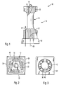
- Exposed light curing device 10 has a heat sink 12 which is arranged in the course of the gun-shaped light curing device.
- a battery pack and a release button is mounted in the handle of the light curing device, and on the upper side in addition a display device for displaying the operating state of the trained as a hand-held light curing device.
- the heat sink 12 carries according to the invention a light source 14 at its front end.
- the light source 14 is designed as an LED or as a multiple arrangement of LEDs and emits both light and heat.
- the emitted light output is conducted via a light guide - possibly with the aid of reflectors - in the mouth of the patient when the dentist performs the light curing of the dental restoration part.
- the heat sink 12 has a centrally extending heat conductor bar 18 as the copper core, so that the heat is dissipated particularly well in the axial direction of the elongate heat sink 12.
- the heat sink 12 has a substantially dumbbell-like construction.
- cooling ribs 20 extend in a star-shaped manner.
- star-shaped cooling ribs 22 extend, while between the front and the rear cooling ribs 20 and 22 a recess 24 is provided which extends extends circularly and offers a free space.
- All cooling fins 20 and 22 extend parallel to an axis 26 of the heat sink 12, which coincides with the optical axis of the light source 14.
- the cooling fins 22 are substantially longer in the axial direction than the cooling fins 20. While each cooling fin 20 is about as long as it is high, the cooling fins 22 occupy at least about one third of the total length of the heat sink 12.
- a fan 30 is flanged, which passes a cooling air flow 32 through the heat sink 12.
- the cooling air flow sweeps along the cooling fins 20 and 22 and also passes through the recess 24. It is as Compressed air flow formed, as explained in detail below.
- the heat sink 12 has in the front of the Fig. 2 apparent cooling fins 20. Through the longitudinally extending cooling fins 20 and 22 through the blower 30 is visible with its flow outlet.
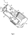
- the light curing device has the heat sink 12 surrounding printed circuit boards 34, 36, 38 and 40, which extend in so far substantially cuboid.
- the printed circuit boards completely surround the heat sink 12 and to this extent form a flow channel for the provision of the cooling air flow through the heat sink.
- the fan 30 has two opposing air inlet slots 42, which are left in a rear wall 44 of the blower housing. In known manner, the blower 30 is driven by an electric motor 46.
- FIG. 4 can be seen in which way the structure of heat sink and PCB can be mounted.
- a front printed circuit board 50 surrounds the light source 14, which is connected via a substrate 52 with the heat conduction bar 18, not shown.
- the substantially axially parallel extending printed circuit boards are hinged.
- one joint is provided, in Fig. 4 the joints 54 and 56 are shown by way of example.
- the printed circuit board 34 is shown in the pivoted state, while the printed circuit boards 36 and 38 are shown in the assembled state.
- the printed circuit boards each carry components, wherein for the printed circuit board 34 by way of example a plurality of components 60 is shown.
- the components 60 extend into the recess 24 and are so far in the cooling air flow 32 of the blower 30.
- they are connected in good heat conduction with the printed circuit board 34, on the large area also sweeps along cooling air.
- copper conductor also results in a good cooling of the components 60th
- the printed circuit boards 34 to 40 do not extend exactly cuboid, but slightly tapered forward. As a result, the flow cross-section in the region of the rear cooling ribs 22 is greater and lower in the region of the front cooling ribs 20. Accordingly, the flow velocity is greater in the front, hot region, while more time remains in the rear region for the cooling air to absorb the heat.
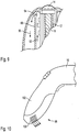
- FIG. 5 it can be seen how the cooling air flow 32 is deflected.
- the cooling air is first introduced into the heat sink via the fan 64 and flows forward, that is to say in the direction of the light source 14.
- a deflection 70 for the cooling air flow is provided in the front corners of the substantially cuboidal printed circuit board arrangement. Accordingly, in the front corners, the printed circuit board arrangement has practically relatively large and wide slots, which allow a deflection of the cooling air flow to the rear.
- the cooling air flow accordingly extends to the rear, corresponding to the arrows 72.
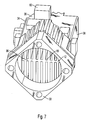
- the heat sink 12 has a heat conducting rod 80, which extends substantially parallelepipedally from solid, good heat-conducting metal along and is provided for receiving the light source on its front end face 82.
- the light source adjacent no additional cooling fin arrangement is provided.
- the Fig. 6 is not apparent and has at its rear region on the cooling ribs 22, which are so far with extremely low thermal resistance associated with the light source.
- the blower 30 is mounted, whose outer circumference substantially corresponds to the extent of the cooling fins, so that a compact unit of the heat sink 12 and the blower 30 is formed. It is particularly advantageous that the substantially square housing of the blower 30 is arranged at an angle of approximately 45 ° to the transverse extent of the furnishedleitstab 80, so that via a flange 84, the fan 30 is well fastened and still the cooling fins 22 on practically the entire effective area of the blower 30 extend.
- Fig. 7 Furthermore, it is provided that it is provided that it is provided that it is provided that the heat-conducting rod 80 are provided over a large area printed circuit boards, of which the printed circuit boards 34, 36 and 38 from FIG. 7 can be seen, wherein the components 60 extend in this embodiment, on the side remote from the heat sink side of the printed circuit boards 34 to 38. This allows a large-area heat conduction connection between the printed circuit boards 34 to 38 and the nuclearleitstab 80, so that a solid state cooling for the components 60 can be realized.
- the components 60 are also in this embodiment in the cooling air flow, and it is preferable to arrange the particularly heat-sensitive devices 60 on the printed circuit board 36 and the printed circuit board 40, which are fully in the cooling air flow, while the cooling air flow for the components on the printed circuit boards 34 and 38th is provided only as a secondary air flow.
- the light source 14 can be applied to the end face 82 of the heat conducting rod 80.
- the light source 14 has five cross-shaped LED chips mounted on a common substrate 90, which is in large contact with the end face 82, so that the heat generated by the light source 14 with very low thermal resistance in the Thermal Conductor 80 is initiated.
- the printed circuit boards 36 and 40 are pulled over the substrate 90 to the front so that they provide terminal lugs 92, which are available for contacting the front printed circuit board, not shown, on the substrate 90 for the supply of the light source.
- the front-printed circuit board then extends between the terminal lugs 92 of the opposing printed circuit boards 36 and 40th
- the introduced heat is additionally passed via these tracks in the rear area, where by the intense cooling air flow, which is generated by the blower 30, the cooling for the printed circuit boards 36 and 40 is realized areally.
- the cooling air flow is preferably deflected in order to achieve the desired cooling, in particular also of the components 60.
- the cooling air flow is deflected in the region of a deflection 94, which is adjacent to the light source 14, to a second cooling air channel 96.
- the air flows along the inside of the housing and enters - as it is Fig. 10 can be seen - at the rear end 98 of cooling air slots 100 from a handle 102 of the prismatic light curing device 10 from.
Description
Die Erfindung betrifft ein Lichthärtgerät, gemäß dem Oberbegriff von Anspruch 1.The invention relates to a light curing apparatus, according to the preamble of claim 1.
Lichthärtgeräte, bei denen die von der Lichtquelle erzeugte Wärme über Kühlkörper abgeführt wird, die in der Regel von einem Gebläse beaufschlagt sind, sind seit langem bekannt. So zeigt die DE-GM 81 35 468 ein Dental-Photopolymerisationsgerät, bei dem ein Kühlkörper dort anfallende Wärme ableiten soll. Der Kühlkörper liegt im Kühlluftstrom eines Kühlgebläses.Light-curing devices in which the heat generated by the light source is dissipated via heat sinks, which are usually acted upon by a fan, have long been known. Thus, DE-GM 81 35 468 shows a dental photopolymerization device in which a heat sink there is expected to dissipate heat. The heat sink is located in the cooling air flow of a cooling fan.
In neuerer Zeit sind Lichthärtgeräte bekannt geworden, die mit ausgesprochen hoher Leistung arbeiten. Die Leistung wird entweder durch LEDs oder durch Laserdioden erzeugt und dient der Polymerisation des Dentalrestaurationsteils, bei Handgeräten typischerweise im Mund des Patienten.In recent times, light curing devices have become known that work with extremely high power. The power is generated either by LEDs or by laser diodes and is used for the polymerization of the dental restoration part, in handheld devices typically in the mouth of the patient.
Ein Beispiel für ein derartiges Lichthärtgerät, das mit einer Laserdiode arbeitet, ist aus der
Ferner ist es gemäß der
Ferner ist auch die Verwendung von sogenannten Heat Pipes vorgeschlagen worden. Derartige Heat Pipes sind seit längerem bekannt und dienen dazu, an einer Stelle erzeugte Wärme an eine entfernte Stelle zu leiten und dort abzuführen. Für Lichthärtgeräte als Handgeräte haben sich derartige Lösungen jedoch als eher unhandlich herausgestellt.Furthermore, the use of so-called heat pipes has been proposed. Such heat pipes have been known for a long time and serve to conduct heat generated at one point to a remote location and remove it there. For light curing devices as handheld devices, however, such solutions have turned out to be rather unwieldy.
Lichthärtgeräte müssen - gerade als Handgeräte - besonders kompakt sein. Daher werden häufig von einem Kühlluftstrom, der über ein Gebläse erzeugt wird, beaufschlagte Kühlkörper eingesetzt, um die von der Lichtquelle erzeugte Wärme abzuführen. Andererseits darf der Kühlluftstrom nicht im Bereich der Lichtquelle, also an der Vorderseite des Lichthärtgeräts ausblasen, da ansonsten der Patient und die Behandlungsstelle von dem austretenden Kühlluftstrom beeinträchtigt würde.Light curing devices - especially as handheld devices - have to be particularly compact. Therefore, heatsinks acted upon by a cooling air flow generated by a blower are often used to dissipate the heat generated by the light source. On the other hand, the cooling air flow must not blow out in the region of the light source, ie on the front side of the light curing device, since otherwise the patient and the treatment site would be adversely affected by the exiting cooling air flow.
Bei einem geringen zur Verfügung stehenden Querschnitt für den Kühlluftstrom muss für den Wärmetausch ein entsprechend vergrößerter Druckaufbau durch das Gebläse erfolgen, um zur Überwindung der Strömungswiderstände den erwünschten Kühlluftstrom bereitzustellen. Bekanntlich erlaubt ein Gebläse in Saugbetrieb höchstens die Bereitstellung von einer Druckdifferenz von einem Bar, wobei dieser Wert auch nur theoretisch erreichbar ist.With a small available cross-section for the cooling air flow, a correspondingly increased pressure build-up by the fan must take place for the heat exchange in order to provide the desired cooling air flow in order to overcome the flow resistances. As is known, a fan in suction mode allows at most the provision of a pressure difference from a bar, and this value can only be achieved theoretically.
Für die Bereitstellung einer größeren Druckdifferenz ist daher die Realisierung eines Gebläses im Druckbetrieb erforderlich.For the provision of a larger pressure difference, therefore, the realization of a blower in the printing operation is required.
Wenn die Strömungsrichtung eines Kühlerstroms bei einem Lichthärtgerät nun von vorne nach hinten erwünscht ist, müsste insofern das Gebläse im vorderen Bereich des Lichthärtgeräts angeordnet sein, wenn es im Druckbetrieb arbeiten soll. Dies verträgt sich andererseits nicht mit der Realisierung der Lichtquelle an dieser Stelle.If the direction of flow of a radiator flow in a light curing device is now desired from the front to the rear, the blower would have to be arranged in the front region of the light curing device if it is to operate in the printing mode. On the other hand, this is incompatible with the realization of the light source at this point.
Für die Bereitstellung der elektrischen Ansteuerung der Lichtquelle sind Bauelemente erforderlich, die ebenfalls im Lichthärtgerät untergebracht werden müssen. Nachdem der Kühlkörper - abgesehen von den Akkumulatoren - das schwerste Bauteil in dem Lichthärtgerät ist, ist es erforderlich, eine ausgewogene Anordnung der Bauelemente zu realisieren, wobei es auch bereits bekannt geworden ist, die Bauelemente im Griff des Lichthärtgeräts unterzubringen.
Diese Aufgabe wird erfindungsgemäß durch Anspruch 1 gelöst. Vorteilhafte Weiterbildungen ergeben sich aus den Unteransprüche.This object is achieved by claim 1. Advantageous developments emerge from the subclaims.
Erfindungsgemäß besonders günstig ist es, wenn die von der Lichtquelle erzeugte Wärme umgehend von der Lichtquelle abgeführt wird. Hierzu ist es erfindungsgemäß besonders günstig, wenn ein Wärmeleiterstab, der beispielsweise einen Kupferkern aufweisen kann, mit niedrigem Wärmewiderstand mit der Lichtquelle gekoppelt ist und sich von der Lichtquelle nach hinten erstreckt.According to the invention, it is particularly advantageous if the heat generated by the light source is removed immediately from the light source. For this purpose, it is particularly advantageous according to the invention if a heat conductor rod, which may have, for example, a copper core, is coupled with low heat resistance to the light source and extends backwards from the light source.
Der Wärmeleiterstab führt dann die Wärme der Lichtquelle nach hinten ab, also weg vom Patienten. Die Kühlung kann dann über am rückwärtigen Ende des Wärmeleiterstabs angebrachte Kühlrippen erfolgen. Erfindungsgemäß lässt sich erreichen, dass nahezu der gesamte Lauf des im Wesentlichen pistolenförmigen Lichthärtgeräts für die Kühlung ausgenutzt wird. Das Gebläse kann dann unmittelbar an dem rückwärtigen Kühlkörperteil an die dortigen Kühlrippen angeflanscht werden.The heat conductor bar then carries the heat from the light source to the rear, ie away from the patient. The cooling can then take place via attached to the rear end of the heat conductor rod cooling fins. According to the invention, it can be achieved that almost the entire barrel of the essentially pistol-shaped light curing device is utilized for the cooling. The blower can then be flanged directly to the rear heat sink part to the local cooling fins.
Erfindungsgemäß besonders vorteilhaft ist es, wenn die Kühlung über einen guten Wärmeleiter, der bevorzugt als metallischer Wärmeleitstab ausgebildet ist, erfolgt. Dieser ist lageunabhängig und vermag in allen Zuständen die von der Lichtquelle eingebrachte Wärme sicher nach hinten abzuleiten. Durch die Verwendung eines massiven Metallstabs lässt sich dessen Wärmekapazität ausnutzen, so dass durch die eingeschaltete Lichtquelle schwerpunktmäßig zunächst die Wärmekapazität des Kupferkerns ausgenutzt und dieser aufgeheizt wird. Über eine an sich bekannte Nachlaufsteuerung des Gebläses lässt sich dann die eingebrachte Wärme sicher und über die Zeit verteilt abführen. Die Kombination der Wärmeableitung recht weit nach hinten in Verbindung mit der Pufferkapazität ist besonders günstig, denn beim Nachlaufen stört das Gebläse regelmäßig nicht, da das Lichthärtgerät dann bereits abgestellt ist.According to the invention, it is particularly advantageous if the cooling takes place via a good heat conductor, which is preferably designed as a metallic heat conductor. This is position-independent and is able to safely divert the heat introduced by the light source in all states to the rear. By use a solid metal rod can be exploited its heat capacity, so that initially exploited by the switched light source, the heat capacity of the copper core and this is heated. About a known per se tracking control of the blower can then dissipate the introduced heat safely and distributed over time. The combination of heat dissipation quite far back in conjunction with the buffer capacity is particularly favorable, because when running after disturbing the blower regularly, since the light curing device is then already turned off.
Erfindungsgemäß besonders günstig ist es, dass Bauelemente mindestens teilweise im Kühlluftstrom des Kühlluftkörpers angeordnet sind. Hierdurch lässt sich zum einen Platz sparen, denn die Unterbringung der Bauelemente ist dann kompakt möglich. Überraschend stören gerade bei einer hohen durch das Gebläse erzeugten Druckdifferenz die zusätzlichen Bauelemente gegenüber dem Kühlkörper als Hauptwiderstand nicht oder nahezu nicht. Dennoch können sie auch besonders gut gekühlt werden, was gerade bei Leistungshalbleitern für die Ansteuerung der Lichtquelle besonders relevant ist.According to the invention, it is particularly favorable that components are arranged at least partially in the cooling air flow of the cooling air body. This saves space, because the placement of the components is then possible in a compact manner. Surprisingly, especially at a high pressure difference generated by the blower, the additional components do not interfere or almost do not disturb the heat sink as the main resistance. Nevertheless, they can also be cooled particularly well, which is especially relevant for power semiconductors for the control of the light source.
Wenn beispielsweise ein Mehrfachanordnung von Leuchtdioden für die Lichtquelle verwendet wird, kann die abgegebene Leistung durchaus im Bereich von 30 W oder höher liegen, wobei die Ansteuerung aus EMV-Gründen zweckmäßig ungetaktet erfolgt, so dass entsprechend große Verlustleistungen der Leistungshalbleiter anfallen.If, for example, a multiple array of light emitting diodes is used for the light source, the output power can well be in the range of 30 W or higher, the control for EMC reasons expediently undacted, so that correspondingly large power losses incurred by the power semiconductors.
Gleichsam automatisch werden die Bauelemente, die sich im Kühlluftstrom befinden, gekühlt. Zusätzlich erfüllt auch die Printplatte für die Aufnahme der Bauelemente eine Doppelfunktion, denn dort erfolgt nicht nur die Kontaktierung und Montage der Bauelemente sondern zugleich auch das Leiten der Luftströmung die den Kühlluftstrom bildet. Hierdurch ist es sichergestellt, dass der Kühlluftstrom für seine Führung nicht eines gesonderten Kunststoffeinsatzes bedarf, so dass in überraschend einfacher Weise das hierfür erforderliche zusätzliche Gewicht entfallen kann.Almost automatically, the components that are in the cooling air flow, cooled. In addition, the printed circuit board for receiving the components also fulfills a dual function, because there is not only the contacting and assembly of the components but also at the same time the guiding of the air flow which forms the cooling air flow. This ensures that the cooling air flow for his leadership does not require a separate plastic insert, so that in a surprisingly simple Way the extra weight required for this can be omitted.
Besonders günstig in diesem Zusammenhang ist es, dass die Printplatte dann praktisch als zusätzliche Kühlfläche eingesetzt werden kann. Durch die typischerweise auf der Printplatte realisierten Kupferschichten wird die Wärme von strombeaufschlagten Widerständen usw. über die Printplatte verteilt, und nachdem die Printplatte sich zur Führung des Kühlluftstroms erstreckt, der Kühlluftstrom also insofern an ihr entlang streicht, wird sie mitgekühlt.Particularly favorable in this context is that the printed circuit board can then be used practically as an additional cooling surface. Due to the copper layers typically realized on the printed circuit board, the heat is distributed over the printed circuit board by current-carrying resistors, etc., and after the printed circuit board extends to guide the cooling air flow, the cooling air flow thus sweeps along it, so that it is co-cooled.
Erfindungsgemäß ist es vorgesehen, dass die Printplatte der Führung des Kühlluftstroms dient. Hierzu kann die Printplatte in beliebiger geeigneter Weise flächig ausgebildet sein, so dass der Kühlluftstrom auf einer Seite, nämlich bevorzugt auf der, auf der sie mit Bauelementen hauptsächlich bestückt ist, entlang streicht. Bevorzugt ist in diesem Zusammenhang die Realisierung von mindestens zwei, weiter bevorzugt von 4 Printplatten, die zueinander im Winkel befestigt sind, so dass sie praktisch eine Art Quader bilden, in dem der Kühlluftstrom strömt.According to the invention, it is provided that the printed circuit board is used to guide the cooling air flow. For this purpose, the printed circuit board may be formed in any suitable manner surface, so that the cooling air flow on one side, namely preferably on the, on which it is mainly equipped with components, sweeps along. Preference is given in this context to the realization of at least two, more preferably of 4 printed circuit boards, which are attached to each other at an angle, so that they form practically a kind of parallelepiped, in which the cooling air flow flows.
Es versteht sich, dass anstelle dessen auch eine beliebige andere Formgebung der Printplatten und damit des Kühlluftstroms realisierbar ist.It is understood that instead of any other shape of the printed circuit boards and thus the cooling air flow can be realized.
Beispielsweise kann auch ein Teil der Printplatte oder eine zusätzlich kleine Printplatte nach der Art einer Rippe im Kühlluftstrom stehen, so dass dort eine besonders intensive Kühlung realisiert ist.For example, a part of the printed circuit board or an additional small printed circuit board in the manner of a rib in the cooling air flow, so that there is a particularly intensive cooling is realized.
In vorteilhafter Ausgestaltung der Erfindung ist es vorgesehen, den Kühlluftstrom im Blasbetrieb zu realisieren, aber dennoch das Gebläse für die Erzeugung des Kühlluftstroms im rückwärtigen Bereich anzuordnen. Überraschend gelingt dies mit einer Strömungsumlenkung im vorderen Bereich, also im Bereich der Lichtquelle, über welche der Kühlluftstrom umgelenkt und dann seitlichen Auslassschlitzen zugeleitet wird, die aufgrund ihres vergleichsweise großen Strömungsquerschnitts ein Ausströmen mit einer niedrigen Strömungsgeschwindigkeit erlauben.In an advantageous embodiment of the invention, it is provided to realize the cooling air flow in the blowing operation, but still to arrange the fan for the generation of the cooling air flow in the rear region. Surprisingly, this is achieved with a flow deflection in the front region, ie in the region of the light source, via which the cooling air flow is deflected and then lateral Outlet slots is fed, which allow due to their comparatively large flow cross-section, a discharge at a low flow rate.
Zugleich lässt sich erfindungsgemäß die Anordnung der Bauelemente im Kühlluftstrom besonders leicht realisieren. Hierzu sind sie radial seitlich des Wärmeleitstabs angeordnet und ragen so in Strömungsrichtung hinter den Haupt-Kühlrippen in den Kühlluftstrom hinein.At the same time, according to the invention, the arrangement of the components in the cooling air flow can be realized particularly easily. For this purpose, they are arranged radially to the side of the Wärmeleitstabs and protrude in the flow direction behind the main cooling fins into the cooling air flow.
Erfindungsgemäß ist es auch günstig, wenn mindestens eine der Printplatten schwenkbeweglich an einer weiteren Printplatte gelagert ist. Auf diese Weise lässt sich zu Reparatur- und Montagezwecken ein leichterer Zugang zu der Printplattenanordnung gewährleisten, die beispielsweise als Quader ausgebildet sein kann aber auch einen beliebigen anderen Querschnitt, beispielsweise einen dreieckigen, fünfeckigen oder anderen Querschnitt haben kann.According to the invention it is also advantageous if at least one of the printed circuit boards is mounted pivotably on a further printed circuit board. In this way, for repair and assembly purposes ensure easier access to the printed circuit board assembly, which may be formed for example as a cuboid but can also have any other cross-section, for example, a triangular, pentagonal or other cross-section.
Während vier Printplatten für die Printplattenanordnung bevorzugt sind, versteht es sich, das anstelle dessen der Kühlluftstrom auch von lediglich zwei Printplatten geführt sein kann, so dass die gegenüberliegende Seite durch das Gehäuse des Lichthärtgeräts oder einen zusätzlichen Kunststoffeinsatz gebildet ist.While four printed circuit boards are preferred for the printed circuit board assembly, it is understood that instead of the cooling air flow may also be performed by only two printed circuit boards, so that the opposite side is formed by the housing of the light curing device or an additional plastic insert.
Gemäß einer weiteren vorteilhaften Ausgestaltung der Erfindung ist es vorgesehen, dass das Lichthärtgerät Bauelemente aufweist, die sich insbesondere neben dem Wärmeleitstab aus Metall auf wenigestens einer Printplatte befinden.According to a further advantageous embodiment of the invention, it is provided that the light curing device comprises components which are in particular in addition to the thermal conductivity of metal on at least one printed circuit board.
Gemäß einer weiteren vorteilhaften Ausgestaltung der Erfindung ist es vorgesehen, sich wenigstens die Bauelemente an einer kühlrippenfreien Stelle befinden.According to a further advantageous embodiment of the invention, it is provided that at least the components are located at a cooling rib free point.
Gemäß einer weiteren vorteilhaften Ausgestaltung der Erfindung ist es vorgesehen, dass die Bauelemente und/oder die Printplatte den Kühlkörper (12) mindestens teilweise umgebend angeordnet sind.According to a further advantageous embodiment of the invention, it is provided that the components and / or the printed circuit board the heat sink (12) are arranged at least partially surrounding.
Gemäß einer weiteren vorteilhaften Ausgestaltung der Erfindung ist es vorgesehen, dass die Bauelemente und/oder die Printplatte in radialen Freiräumen aufgenommen sind, die von den Kühlrippen des Kühlkörpers und von einem Kern des Kühlkörpers begrenzt sind.According to a further advantageous embodiment of the invention, it is provided that the components and / or the printed circuit board are received in radial clearances, which are bounded by the cooling fins of the heat sink and a core of the heat sink.
Gemäß einer weiteren vorteilhaften Ausgestaltung der Erfindung ist es vorgesehen, dass wenigstens eine Printplatte mindestens teilweise an dem Kühlkörper gelagert ist und sich insbesondere seitlich an dem Kühlkörper entlang erstreckt.According to a further advantageous embodiment of the invention, it is provided that at least one printed circuit board is at least partially mounted on the heat sink and in particular laterally extends along the heat sink.
Gemäß einer weiteren vorteilhaften Ausgestaltung der Erfindung ist es vorgesehen, dass mindestens drei Printplatten, insbesondere vier Printplatten, den Kühlkörper umgeben.According to a further advantageous embodiment of the invention, it is provided that at least three printed circuit boards, in particular four printed circuit boards, surround the heat sink.
Gemäß einer weiteren vorteilhaften Ausgestaltung der Erfindung ist es vorgesehen, dass mindestens eine Printplatte gegenüber einer weiteren Printplatte beweglich gelagert ist, insbesondere schwenkbar gelagert ist.According to a further advantageous embodiment of the invention, it is provided that at least one printed circuit board is movably mounted relative to a further printed circuit board, in particular is mounted pivotably.
Gemäß einer weiteren vorteilhaften Ausgestaltung der Erfindung ist es vorgesehen, dass die Printplatte, insbesondere alle Bauelemente, auf ihrer dem Kühlkörper zugewandten oder ihrer vom Kühlkörper abgewandten Seite trägt.According to a further advantageous embodiment of the invention, it is provided that the printed circuit board, in particular all components, on its side facing the heat sink or its side facing away from the heat sink side carries.
Gemäß einer weiteren vorteilhaften Ausgestaltung der Erfindung ist es vorgesehen, dass mindestens eine Printplatte auf dem Wärmeleitstab aus Metall des Kühlkörpers aufgebracht und dort isoliert aufliegt und insbesondere in Wärmeleitverbindung mit dem Wärmeleitstab steht.According to a further advantageous embodiment of the invention, it is provided that at least one printed circuit board is applied to the heat conduction made of metal of the heat sink and rests there insulated and in particular is in thermal conduction connection with the Wärmeleitstab.
Gemäß einer weiteren vorteilhaften Ausgestaltung der Erfindung ist es vorgesehen, dass der Wärmeleitstab aus Metall im Wesentlichen als Quader ausgebildet ist und insbesondere an allen vier Seiten von Printplatten umgeben ist.According to a further advantageous embodiment of the invention, it is provided that the Wärmeleitstab made of metal substantially is formed as a cuboid and is surrounded in particular on all four sides of printed circuit boards.
Gemäß einer weiteren vorteilhaften Ausgestaltung der Erfindung ist es vorgesehen, dass die Bauelemente mit der Printplatte in Wärmeleitverbindung stehen und die Printplatte als Kühlement ausgebildet ist, über welches die von den Bauelementen abgegebene und in die Printplatte eingeleitete Wärme über den Kühlluftstrom abgebbar ist.According to a further advantageous embodiment of the invention, it is provided that the components are in thermal communication with the printed circuit board and the printed circuit board is designed as a cooling element, via which the output from the components and introduced into the printed circuit heat via the cooling air flow can be delivered.
Gemäß einer weiteren vorteilhaften Ausgestaltung der Erfindung ist es vorgesehen, dass sich zwischen mindestens einer Printplatte und dem Wärmeleitstab und/oder Kühlkörper ein erster Kühlluftkanal erstreckt.According to a further advantageous embodiment of the invention, provision is made for a first cooling air channel to extend between at least one printed circuit board and the heat-conducting rod and / or heat sink.
Gemäß einer weiteren vorteilhaften Ausgestaltung der Erfindung ist es vorgesehen, dass sich ein zweiter Kühlluftkanal zwischen den Printplatten und einem Gehäuse des Lichthärtgeräts oder zwischen zwei Gehäuseteilen des Lichthärtgeräts erstreckt. Erfindungsgemäß ist es vorgesehen, dass der Lichtquelle benachbart zwischen zwei Gehäuseteilen oder zwischen wenigestens einer Printplatte und dem Gehäuse eine Umlenkung für den Kühlluftstrom vorgesehen ist, über welche der Kühlluftstrom um mindestens 90°, insbesondere um mehr als 150°, umgelenkt wird.According to a further advantageous embodiment of the invention, it is provided that a second cooling air channel extends between the printed circuit boards and a housing of the light curing device or between two housing parts of the light curing device. According to the invention, it is provided that the light source adjacent between two housing parts or between at least one printed circuit board and the housing, a deflection for the cooling air flow is provided, via which the cooling air flow by at least 90 °, in particular by more than 150 °, is deflected.
Gemäß einer weiteren vorteilhaften Ausgestaltung der Erfindung ist es vorgesehen, dass der Kühlluftstrom von einem Gebläse erzeugt wird und die kühle Luft die Kühlrippen und insbesondere auch die Bauelemente beaufschlagt. Erfindungsgemäß ist es vorgesehen, dass das Gebläse an der von der Lichtquelle abgewandten Stirnseite des Kühlkörpers angeordnet ist. Erfindungsgemäß ist es vorgesehen, dass der Kühlluftstrom zuerst den ersten Kühlluftkanal und nach der Umlenkung den ersten Kühlluftkanal oder umgekehrt passiert.According to a further advantageous embodiment of the invention, it is provided that the cooling air flow is generated by a fan and the cool air acts on the cooling fins and in particular also the components. According to the invention, it is provided that the fan is arranged on the end face of the heat sink facing away from the light source. According to the invention, it is provided that the cooling air flow first passes through the first cooling air channel and after the deflection the first cooling air channel or vice versa.
Gemäß einer weiteren vorteilhaften Ausgestaltung der Erfindung ist es vorgesehen, dass der Kühlluftstrom nach dem Passieren der beiden Kühlluftkanäle das Gehäuse in einem Endbereich eines Handgriffes des Lichthärtgeräts verlässt.According to a further advantageous embodiment of the invention, it is provided that the cooling air flow leaves the housing in an end region of a handle of the light curing device after passing through the two cooling air channels.
Gemäß einer weiteren vorteilhaften Ausgestaltung der Erfindung ist es vorgesehen, dass zwei einander gegenüberliegende Printplatten zur Lichtquelle vorragen und dort Anschlussfahnen einer Stirnprintplatte kontaktieren, die sich im Wesentlichen rechtwinklig zu den Printplatten erstreckt und über welche die Lichtquelle angeschlossen ist.According to a further advantageous embodiment of the invention, it is provided that two opposing printed circuit boards protrude to the light source and there contact terminal lugs a Stirnprintplatte, which extends substantially perpendicular to the printed circuit boards and through which the light source is connected.
Gemäß einer weiteren vorteilhaften Ausgestaltung der Erfindung ist es vorgesehen, dass der Wärmeleitstab insbesondere aus Kupfer, und der Kühlkörper, insbesondere aus Aluminium oder einer Aluminiumlegierung, besteht.According to a further advantageous embodiment of the invention, it is provided that the heat-conducting rod consists in particular of copper, and the heat sink, in particular of aluminum or an aluminum alloy.
Gemäß einer weiteren vorteilhaften Ausgestaltung der Erfindung ist es vorgesehen, dass die Bauelemente, gesehen über die Längserstreckung des Kühlkörpers , in der Höhe des Wärmeleitstabs mit geringem Wärmewiderstand oder einer heat pipe angeordnet sind.According to a further advantageous embodiment of the invention, it is provided that the components, as seen over the longitudinal extension of the heat sink, in the height of the Wärmeleitstabs with low thermal resistance or a heat pipe are arranged.
Weitere Vorteile, Einzelheiten und Merkmale ergeben sich aus der nachfolgenden Beschreibung zweier Ausführungsbeispiele der Erfindung anhand der Zeichnung.Further advantages, details and features will become apparent from the following description of two embodiments of the invention with reference to the drawing.
Es zeigen:
- Fig. 1
- eine Seitenansicht eines Teils eines erfindungsgemäßen Lichthärtgeräts unter Darstellung unter anderem des Kühlkörpers;
- Fig. 2
- eine Stirnansicht der Ausführungsform gemäß
Fig. 1 von vorne; - Fig. 3
- eine rückwärtige Ansicht der Ausführungsform gemäß
Fig. 2 ; - Fig. 4
- eine Ansicht der Ausführungsform gemäß
Fig. 1 bis 3 , wobei mindestens zwei Printplatten bereits montiert sind; - Fig. 5
- eine Seitenansicht des erfindungsgemäßen Lichthärtgeräts in einem weiter montierten Zustand;
- Fig. 6
- eine perspektivische Ansicht eines Kühlkörpers ohne Printplatten in einer weiteren Ausführungsform jedoch mit anmontiertem Gebläse;
- Fig. 7
- eine rückwärtige Ansicht des Kühlkörpers gemäß
Fig. 6 , wobei Printplatten und Bauelemente anmontiert sind; - Fig. 8
- die montierte Einheit aus Kühlkörper, Gebläse und Printplatten, einschließlich der Bauelemente und der Lichtquelle;
- Fig. 9
- ein Detail eines erfindungsgemäßen Lichthärtgeräts in teilweise aufgebrochener Darstellung; und
- Fig. 10
- eine Seitenansicht des Lichthärtgeräts gemäß den vorstehenden Figuren.
- Fig. 1
- a side view of a portion of a light curing device according to the invention showing, inter alia, the heat sink;
- Fig. 2
- an end view of the embodiment according to
Fig. 1 from the front; - Fig. 3
- a rear view of the embodiment according to
Fig. 2 ; - Fig. 4
- a view of the embodiment according to
Fig. 1 to 3 , wherein at least two printed circuit boards are already mounted; - Fig. 5
- a side view of the light curing device according to the invention in a further mounted state;
- Fig. 6
- a perspective view of a heat sink without printed circuit boards in another embodiment, however, with anmontiertem fan;
- Fig. 7
- a rear view of the heat sink according to
Fig. 6 where printed circuit boards and components are mounted; - Fig. 8
- the assembled unit of heat sink, fan and printed circuit board, including the components and the light source;
- Fig. 9
- a detail of a light curing device according to the invention in a partially broken view; and
- Fig. 10
- a side view of the light curing device according to the preceding figures.
Das in
Der Kühlkörper 12 trägt erfindungsgemäß eine Lichtquelle 14 an seiner vorderen Stirnseite. Die Lichtquelle 14 ist als LED oder als Mehrfachanordnung von LEDs ausgebildet und gibt sowohl Licht als auch Wärme ab. Die abgegebene Lichtleistung wird über einen Lichtleiter - ggf. über Zuhilfenahme von Reflektoren - in den Mund des Patienten geleitet, wenn der Zahnarzt die Lichthärtung des Dentalrestaurationsteils vornimmt.The
Die Lichtquelle ist in guter Wärmeleitverbindung mit dem Kühlkörper 12. Der Kühlkörper 12 weist erfindungsgemäß einen sich zentral erstreckenden Wärmeleiterstab 18 als Kupferkern auf, so dass die Wärme besonders gut in axialer Richtung des länglichen Kühlkörpers 12 abgeleitet wird.According to the invention, the
Der Kühlkörper 12 weist einen im Wesentlichen hantelartigen Aufbau auf. In seinem vorderen Bereich, also dem der Lichtquelle 14 benachbarten Bereich, erstrecken sich sternförmig Kühlrippen 20. Zusätzlich erstrecken sich in seinem hinteren Bereich ebenfalls sternförmig Kühlrippen 22, während zwischen den vorderen und den hinteren Kühlrippen 20 und 22 eine Ausnehmung 24 vorgesehen ist, die sich kreisförmig erstreckt und einen Freiraum bietet.The
Sämtliche Kühlrippen 20 und 22 erstrecken sich parallel zu einer Achse 26 des Kühlkörpers 12, die mit der optischen Achse der Lichtquelle 14 zusammenfällt. Die Kühlrippen 22 sind in axialer Richtung wesentlich länger als die Kühlrippen 20. Während jede Kühlrippe 20 etwa so lang wie hoch ist, nehmen die Kühlrippen 22 immerhin etwa ein Drittel der Gesamtlänge des Kühlkörpers 12 ein.All cooling
An der rückwärtigen Stirnseite der des im Querschnitt im Wesentlichen quaderförmigen oder auch in einer modifizierten Ausgestaltung kreisförmigen Kühlkörpers 12 ist ein Gebläse 30 angeflanscht, das einen Kühlluftstrom 32 durch den Kühlkörper 12 hindurchleitet. Der Kühlluftstrom streicht an den Kühlrippen 20 und 22 entlang und durchtritt auch die Ausnehmung 24. Er ist als Druckluftstrom ausgebildet, wie es weiter unten im Einzelnen erläutert ist.At the rear end side of the in cross section substantially cuboidal or in a modified embodiment
Aus
Der Kühlkörper 12 weist im vorderen Bereich die aus
Das Lichthärtgerät weist den Kühlkörper 12 umgebend Printplatten 34, 36, 38 und 40 auf, die sich insofern im Wesentlichen quaderförmig erstrecken. Die Printplatten umschließen den Kühlkörper 12 vollständig und bilden insofern einen Strömungskanal für die Bereitstellung des Kühlluftstroms durch den Kühlkörper hindurch.The light curing device has the
Aus
Aus
Die Printplatten tragen je Bauelemente, wobei für die Printplatte 34 beispielhaft eine Vielzahl von Bauelementen 60 dargestellt ist. Die Bauelemente 60 erstrecken sich in die Ausnehmung 24 hinein und liegen insofern im Kühlluftstrom 32 des Gebläses 30. Zusätzlich sind sie in guter Wärmeleitverbindung mit der Printplatte 34 verbunden, an der großflächig ebenfalls Kühlluft entlang streicht. Hierdurch und durch die auf der Printplatte 34 vorgesehenen Kupferleiter ergibt sich ebenfalls eine gute Kühlung der Bauelemente 60.The printed circuit boards each carry components, wherein for the printed
Die Printplatten 34 bis 40 erstrecken sich nicht exakt quaderförmig, sondern leicht verjüngt nach vorne. Hierdurch ist der Strömungsquerschnitt im Bereich der rückwärtigen Kühlrippen 22 größer und im Bereich der vorderen Kühlrippen 20 geringer. Die Strömungsgeschwindigkeit ist dementsprechend im vorderen, heißen Bereich, größer, während im rückwärtigen Bereich mehr Zeit für die Kühlluft verbleibt, die Wärme aufzunehmen.The printed
Aus
Etwa in der axialen Mitte des Kühlkörpers sind sich nach außen erstreckende Kühlluftschlitze 74 ausgebildet, die großflächig den Austritt der verbrauchten Kühlluft entsprechend den Pfeilen 76 ermöglichen.Approximately in the axial center of the heat sink outwardly extending
Über diese Kühlluftführung ist es möglich, eine Druckluftversorgung des Kühlluftstrom 32 bereitszustellen, wobei dennoch der vordere Bereich 78 des Lichthärtgeräts vollständig frei von Kühlluft verbleibt und insbesondere der Patient nicht angeblasen wird.About this cooling air duct, it is possible to already provide a compressed air supply of the cooling
Eine weitere Ausführungsform ist aus den
Bei dieser Ausführungform ist der Lichtquelle benachbart keine zusätzliche Kühlrippenanordnung vorgesehen. Dafür hat der Wärmeleitstab 80 einen Kupferkern, der aus
An die Kühlrippen angeflanscht ist das Gebläse 30 angebracht, dessen Außenumfang im Wesentlichen der Erstreckung der Kühlrippen entspricht, so dass eine kompakte Einheit aus dem Kühlkörper 12 und dem Gebläse 30 entsteht. Besonders günstig ist es, dass das im Wesentlichen quadratische Gehäuse des Gebläses 30 im Winkel von etwa 45° versetzt zur Quererstreckung des Wärmeleitstab 80 angeordnet ist, so dass über einen Flansch 84 das Gebläse 30 gut befestigbar ist und sich dennoch die Kühlrippen 22 über praktisch die gesamte wirksame Fläche des Gebläses 30 erstrecken.Flanged to the cooling fins, the
Hierzu ist es, wie aus
Wie aus
Aus
Bei dieser Ausführungsform sind die Printplatten 36 und 40 bis über das Substrat 90 nach vorne gezogen, so dass sie Anschlussfahnen 92 bieten, die für die Kontaktierung der nicht dargestellten Stirn-Printplatte auf dem Substrat 90 für die Versorgung der Lichtquelle zur Verfügung stehen. Die Stirn-Printplatte erstreckt sich dann zwischen den Anschlussfahnen 92 der einander gegenüberliegenden Printplatten 36 und 40.In this embodiment, the printed
Nachdem hier breite Kupferbahnen für die Realisierung eines geringen elektrischen Widerstands verwendet werden, wird die eingeleitete Wärme zusätzlich auch über diese Leiterbahnen in den rückwärtigen Bereich geleitet, wo durch den intensiven Kühlluftstrom, der durch das Gebläse 30 erzeugt wird, die Kühlung für die Printplatten 36 und 40 flächig realisiert ist.After here broad copper tracks are used for the realization of a low electrical resistance, the introduced heat is additionally passed via these tracks in the rear area, where by the intense cooling air flow, which is generated by the
Aus
Claims (18)
- A light-curing apparatus that is formed pistol-shaped, having an elongated cooling body (12) that Is arranged in the barrel of the pistol-shaped light-curing apparatus and carrying a LED light source at the frontal end face that is directly or indirectly coupled to a metal heat-conducting rod (18; 80), that centrally extends within the cooling body (12) and comprising a copper core, wherein the heat-conducting rod (18; 80) is In thermal communication, at least in its end region facing away from the light source (14), with cooling ribs (20, 22) of the cooling body (12), so that the heat generated by the light source (14) is able to be dissipated in an axial direction of the elongated cooling body (12), wherein a deflection for a cooling air stream (32) is provided, adjacent to the light source (14), between two housing parts or between at least print board (34, 36, 38, 40) and a housing, by means of which deflection the cooling air stream (32) is deflected by at least 90°, and wherein the cooling air stream (32) initially passes through a first cooling air passage (92) and, following deflection (70, 94), through a second cooling air passage (96) or vice versa, and wherein a fan (30) Is arranged at the front face of the cooling body (12) facing away from the fight source (14).
- The light-curing apparatus according to Claim 1, characterized in that the light-curing apparatus comprises components (60) that are especially located next to the conducting rod on at least one print board.
- The light-curing apparatus according to Claim 2, characterized in that at least the components (60) are iocated in a position free of cooling ribs, wherein the cooling body (12) is designed such that cooling ribs (20, 22) radially extend in its front region adjacent to the light source (14) and in Its rear region, wherein, between the cooling ribs (20, 22), a circular extending recess (24) defines the location free of cooling ribs.
- Light-curing apparatus according to one of the Claims 1 to 2, characterized In that at least one print board (34, 36, 38, 40) is applied to and isolatedly abuts the heat-conducting rod (80) of the cooling body (12), consisting of solid heat conducting metal, and especially is in thermal communication therewith.
- The light-curing apparatus according to Claim 4, characterized in that the heat-conducting rod (80) essentially is formed as a cuboid and especially is surrounded by print boards (34, 36, 38, 40) at all four sides, and comprising the cooling ribs (22) on its rearward region.
- The light-curing apparatus according to one of the Claims 2 to 5, characterized In that the components (60) and/or the print board (34, 36, 38, 40) is arranged at least partially surrounding the cooling body (12).
- The light-curing apparatus according to one of the Claims 2 to 6, characterized in that the components (60) and/or the print board is accommodated In the radial free spaces, which are confined by the cooling ribs (20, 22) of the cooling body (12) and by a core of the cooling body (12).
- The light-curing apparatus according to one of the preceding Claims, characterized In that at least one print board is at least partially supported to the cooling body (12) and especially extends laterally along the cooling body (12).
- The light-curing apparatus according to one of the preceding Claims, characterized In that at least three print boards (34, 36, 38, 40), especially four print boards (34, 36, 38, 40) surround the cooling body (12).
- The light-curing apparatus according to one of the preceding Claims, characterized in that at least one print board (34; 36; 38; 40) is movably supported, and especially is pivotably supported in relation to another print board (34; 36; 38; 40).
- The light-curing apparatus according to one of the Claims 2 to 10, characterized in that the print board especially carries all components (60) on its surface facing the cooling body (12) or Its surface facing away from the cooling body (12).
- The light-curing apparatus according to one of the Claims 2 to 11, characterized in that the components (60) are in thermal communication with the print board and the print board is formed as a cooling member, through which the heat emitted from the components (60) and introduced into the print board is able to be discharged via the cooling air stream (32).
- The light-curing apparatus according to one of the preceding Claims, characterized in that the first cooling air passage extends between at least one print board (34, 36, 38, 40) and the heat-conducting rod (18) and/or the cooling body (12) .
- The light-curing apparatus according to one of the preceding Claims, characterized in that the second cooling air passage extends between the print boards (34, 36,38, 40) and a housing of the light-curing apparatus or between two housing parts of the light-curing apparatus.
- Light-curing apparatus according to one of the Claims 2 to 14, characterized In that the cooling air stream is supplied from a fan to the cooling ribs (20, 22) and especially also to the components (60).
- The light-curing apparatus according to one of the preceding Claims, characterized in that the cooling air stream, after passing the two cooling air passages (92, 96), exits the housing towards an end region of a handle of the light-curing apparatus.
- The light-curing apparatus according to one of the preceding Claims, characterized in that two print boards (34, 36, 38, 40) opposite to each other protrude towards the light source (14) and there contacting connecting flags of a front print board that essentially extends perpendicular to the print boards (34, 36, 38, 40) and by which the light source (14) are connected.
- The light-curing apparatus according to one of the preceding Claims, characterized in that the heat-conducting rod (18, 80) consists of copper, and the cooling body (12) especially consists of aluminum or an aluminum alloy.
Applications Claiming Priority (1)
| Application Number | Priority Date | Filing Date | Title |
|---|---|---|---|
| DE102006036828A DE102006036828B3 (en) | 2006-08-07 | 2006-08-07 | light curing |
Publications (2)
| Publication Number | Publication Date |
|---|---|
| EP1886643A1 EP1886643A1 (en) | 2008-02-13 |
| EP1886643B1 true EP1886643B1 (en) | 2018-04-04 |
Family
ID=38686630
Family Applications (1)
| Application Number | Title | Priority Date | Filing Date |
|---|---|---|---|
| EP07009726.6A Not-in-force EP1886643B1 (en) | 2006-08-07 | 2007-05-15 | Light hardening device |
Country Status (5)
| Country | Link |
|---|---|
| US (1) | US7976307B2 (en) |
| EP (1) | EP1886643B1 (en) |
| JP (1) | JP4861268B2 (en) |
| DE (1) | DE102006036828B3 (en) |
| ES (1) | ES2676082T3 (en) |
Families Citing this family (14)
| Publication number | Priority date | Publication date | Assignee | Title |
|---|---|---|---|---|
| US7846391B2 (en) | 2006-05-22 | 2010-12-07 | Lumencor, Inc. | Bioanalytical instrumentation using a light source subsystem |
| US8098375B2 (en) | 2007-08-06 | 2012-01-17 | Lumencor, Inc. | Light emitting diode illumination system |
| CN101373064B (en) * | 2007-08-24 | 2011-05-11 | 富准精密工业(深圳)有限公司 | LED light fitting |
| DE102008033556A1 (en) * | 2008-03-14 | 2009-09-17 | Kaltenbach & Voigt Gmbh | Light source for a dental device |
| DE102008031094A1 (en) | 2008-07-01 | 2010-01-07 | Ivoclar Vivadent Ag | Device for light curing a dental object |
| US9763760B2 (en) | 2008-07-01 | 2017-09-19 | Ivoclar Vivadent Ag | Apparatus for light-curing a dental object |
| US8242462B2 (en) | 2009-01-23 | 2012-08-14 | Lumencor, Inc. | Lighting design of high quality biomedical devices |
| TWI467115B (en) * | 2010-08-06 | 2015-01-01 | Ind Tech Res Inst | Light source apparatus with high heat dissipation efficiency |
| US8475285B2 (en) | 2011-08-04 | 2013-07-02 | Megatouch, Llc | Swinging motherboard for amusement device |
| US9217561B2 (en) | 2012-06-15 | 2015-12-22 | Lumencor, Inc. | Solid state light source for photocuring |
| JP6153369B2 (en) * | 2013-04-05 | 2017-06-28 | 日立マクセル株式会社 | Beauty equipment |
| ES2905363T3 (en) | 2014-09-17 | 2022-04-08 | Garrison Dental Solutions Llc | Dental curing light |
| USD810293S1 (en) | 2017-01-20 | 2018-02-13 | Garrison Dental Solutions, Llc | Dental instrument |
| CZ2019588A3 (en) * | 2019-09-16 | 2021-03-24 | Varroc Lighting Systems, s.r.o. | Lighting equipment for motor vehicles |
Family Cites Families (24)
| Publication number | Priority date | Publication date | Assignee | Title |
|---|---|---|---|---|
| DE8135468U1 (en) * | 1981-12-05 | 1982-04-15 | Kulzer & Co Gmbh, 6380 Bad Homburg | "DENTAL PHOTOPOLYMERIZATION DEVICE" |
| US4470101A (en) * | 1982-09-29 | 1984-09-04 | Simmonds Precision Products, Inc. | Apparatus for the mounting and wiring of printed circuit boards |
| DE3719561C2 (en) * | 1986-06-12 | 1998-12-10 | Morita Mfg | Medical light irradiation handpiece |
| JP2713628B2 (en) * | 1990-03-19 | 1998-02-16 | 富士通株式会社 | Heat dissipation structure of surface mount type IC package |
| JPH1027926A (en) * | 1996-07-11 | 1998-01-27 | Nichia Chem Ind Ltd | Photo-semiconductor device |
| JP2001517875A (en) * | 1997-09-25 | 2001-10-09 | ユニバーシティ オブ ブリストル | Light irradiation device |
| US6200134B1 (en) * | 1998-01-20 | 2001-03-13 | Kerr Corporation | Apparatus and method for curing materials with radiation |
| DE19803755C2 (en) * | 1998-01-30 | 2001-03-15 | Ivoclar Ag Schaan | Light curing device |
| US6068474A (en) * | 1998-01-30 | 2000-05-30 | Ivoclar Ag | Light curing device |
| DE19943393C1 (en) * | 1999-09-10 | 2001-01-25 | Espe Dental Ag | Dental material radiation device e.g. for hardening dental filling, has light beams from light-emitting diodes directed onto focus region at input end of light conductor |
| US6171105B1 (en) * | 1999-09-21 | 2001-01-09 | Eg&G Ilc Technology, Inc. | Dental-restoration light-curing system |
| JP4461584B2 (en) * | 1999-11-16 | 2010-05-12 | パナソニック株式会社 | Heat sink device |
| US7320593B2 (en) * | 2000-03-08 | 2008-01-22 | Tir Systems Ltd. | Light emitting diode light source for curing dental composites |
| JP2001327517A (en) * | 2000-05-24 | 2001-11-27 | Sakoguchi:Kk | Apparatus for curing resin |
| DE10127416B4 (en) * | 2001-06-06 | 2008-01-03 | Ivoclar Vivadent Ag | Light curing device and light source with a plurality of LEDs and a heat sink |
| EP1282206A1 (en) * | 2001-07-30 | 2003-02-05 | Agilent Technologies, Inc. (a Delaware corporation) | Method and apparatus for cooling electronic or optoelectronic devices |
| DE10214366B4 (en) | 2002-03-30 | 2017-03-16 | Robert Bosch Gmbh | measuring arrangement |
| US7182597B2 (en) * | 2002-08-08 | 2007-02-27 | Kerr Corporation | Curing light instrument |
| AU2003298561A1 (en) * | 2002-08-23 | 2004-05-13 | Jonathan S. Dahm | Method and apparatus for using light emitting diodes |
| DE10242366B4 (en) * | 2002-09-12 | 2010-10-21 | Ivoclar Vivadent Ag | Light curing device for curing light-curable materials |
| US6890175B2 (en) * | 2002-12-18 | 2005-05-10 | Ultradent Products, Inc. | Cooling system for hand-held curing light |
| US6918762B2 (en) * | 2003-03-21 | 2005-07-19 | Kerr Corporation | Light-generating instrument |
| DE10320141B4 (en) * | 2003-05-06 | 2010-11-25 | Ivoclar Vivadent Ag | light polymerization |
| KR100643516B1 (en) * | 2003-05-06 | 2006-11-10 | 가부시키가이샤 모리타 세이사쿠쇼 | Medical irradiation apparatus |
-
2006
- 2006-08-07 DE DE102006036828A patent/DE102006036828B3/en not_active Expired - Fee Related
-
2007
- 2007-05-15 ES ES07009726.6T patent/ES2676082T3/en active Active
- 2007-05-15 EP EP07009726.6A patent/EP1886643B1/en not_active Not-in-force
- 2007-08-07 JP JP2007205992A patent/JP4861268B2/en not_active Expired - Fee Related
- 2007-08-16 US US11/893,526 patent/US7976307B2/en active Active
Non-Patent Citations (1)
| Title |
|---|
| None * |
Also Published As
| Publication number | Publication date |
|---|---|
| JP4861268B2 (en) | 2012-01-25 |
| EP1886643A1 (en) | 2008-02-13 |
| ES2676082T3 (en) | 2018-07-16 |
| JP2008038155A (en) | 2008-02-21 |
| DE102006036828B3 (en) | 2008-04-17 |
| US20080032254A1 (en) | 2008-02-07 |
| US7976307B2 (en) | 2011-07-12 |
Similar Documents
| Publication | Publication Date | Title |
|---|---|---|
| EP1886643B1 (en) | Light hardening device | |
| DE102015209375B4 (en) | Cooling device and inverter housing with such a cooling device | |
| DE102008051256B4 (en) | Semiconductor radiation source | |
| EP2003744B1 (en) | Gas cooled laser device for highly compact laser beam sources | |
| DE102006057796B4 (en) | Cooling arrangement for heat generating electrical components and electrical equipment with it | |
| EP1398005B1 (en) | Light curing apparatus | |
| DE102005007545B4 (en) | Device and method for cooling an electronics | |
| DE102014105960B4 (en) | LED lighting device with an improved heat sink | |
| WO2006105834A2 (en) | Cooling unit | |
| DE102008060613B4 (en) | Cooling arrangement for a converter arranged in a switch cabinet | |
| EP1995514A2 (en) | Lighting unit | |
| EP1327079A1 (en) | Fan installation | |
| EP2311366A1 (en) | LED lighting module | |
| EP1475052B1 (en) | Photopolymerisation device with a fan | |
| EP1637234A1 (en) | Handheld extrusion welding device | |
| DE10127416B4 (en) | Light curing device and light source with a plurality of LEDs and a heat sink | |
| EP3747350B1 (en) | Device for heat dissipation from an endoscopic illumination device | |
| DE102005026662A1 (en) | Light source for endoscopy or microscopy | |
| EP2114116B1 (en) | Hybrid cooling | |
| EP1922177A1 (en) | Cooling body for an electronic housing | |
| DE10162404A1 (en) | Circuit arrangement for driving LEDs especially in motor vehicle, has power component and LED arranged on common circuit board or common conducting film | |
| EP1972301A1 (en) | Light hardening device - base station combination | |
| EP2181662A2 (en) | Light emitting device and drive device with an LED | |
| EP1478219A2 (en) | Cooling arrangement for a thyristor | |
| DE102019129815B4 (en) | Cooling device for an endoscope or exoscope |
Legal Events
| Date | Code | Title | Description |
|---|---|---|---|
| PUAI | Public reference made under article 153(3) epc to a published international application that has entered the european phase |
Free format text: ORIGINAL CODE: 0009012 |
|
| AK | Designated contracting states |
Kind code of ref document: A1 Designated state(s): AT BE BG CH CY CZ DE DK EE ES FI FR GB GR HU IE IS IT LI LT LU LV MC MT NL PL PT RO SE SI SK TR |
|
| AX | Request for extension of the european patent |
Extension state: AL BA HR MK YU |
|
| 17P | Request for examination filed |
Effective date: 20080225 |
|
| AKX | Designation fees paid |
Designated state(s): AT BE BG CH CY CZ DE DK EE ES FI FR GB GR HU IE IS IT LI LT LU LV MC MT NL PL PT RO SE SI SK TR |
|
| 17Q | First examination report despatched |
Effective date: 20110816 |
|
| GRAP | Despatch of communication of intention to grant a patent |
Free format text: ORIGINAL CODE: EPIDOSNIGR1 |
|
| INTG | Intention to grant announced |
Effective date: 20171024 |
|
| RIN1 | Information on inventor provided before grant (corrected) |
Inventor name: PLANK, WOLFGANG Inventor name: SENN, BRUNO |
|
| GRAS | Grant fee paid |
Free format text: ORIGINAL CODE: EPIDOSNIGR3 |
|
| GRAA | (expected) grant |
Free format text: ORIGINAL CODE: 0009210 |
|
| AK | Designated contracting states |
Kind code of ref document: B1 Designated state(s): AT BE BG CH CY CZ DE DK EE ES FI FR GB GR HU IE IS IT LI LT LU LV MC MT NL PL PT RO SE SI SK TR |
|
| REG | Reference to a national code |
Ref country code: GB Ref legal event code: FG4D Free format text: NOT ENGLISH |
|
| REG | Reference to a national code |
Ref country code: CH Ref legal event code: EP |
|
| REG | Reference to a national code |
Ref country code: AT Ref legal event code: REF Ref document number: 984742 Country of ref document: AT Kind code of ref document: T Effective date: 20180415 |
|
| REG | Reference to a national code |
Ref country code: DE Ref legal event code: R096 Ref document number: 502007016132 Country of ref document: DE |
|
| REG | Reference to a national code |
Ref country code: IE Ref legal event code: FG4D Free format text: LANGUAGE OF EP DOCUMENT: GERMAN |
|
| REG | Reference to a national code |
Ref country code: FR Ref legal event code: PLFP Year of fee payment: 12 |
|
| REG | Reference to a national code |
Ref country code: ES Ref legal event code: FG2A Ref document number: 2676082 Country of ref document: ES Kind code of ref document: T3 Effective date: 20180716 |
|
| REG | Reference to a national code |
Ref country code: SE Ref legal event code: TRGR |
|
| REG | Reference to a national code |
Ref country code: NL Ref legal event code: MP Effective date: 20180404 |
|
| REG | Reference to a national code |
Ref country code: LT Ref legal event code: MG4D |
|
| PG25 | Lapsed in a contracting state [announced via postgrant information from national office to epo] |
Ref country code: NL Free format text: LAPSE BECAUSE OF FAILURE TO SUBMIT A TRANSLATION OF THE DESCRIPTION OR TO PAY THE FEE WITHIN THE PRESCRIBED TIME-LIMIT Effective date: 20180404 |
|
| PG25 | Lapsed in a contracting state [announced via postgrant information from national office to epo] |
Ref country code: FI Free format text: LAPSE BECAUSE OF FAILURE TO SUBMIT A TRANSLATION OF THE DESCRIPTION OR TO PAY THE FEE WITHIN THE PRESCRIBED TIME-LIMIT Effective date: 20180404 Ref country code: BG Free format text: LAPSE BECAUSE OF FAILURE TO SUBMIT A TRANSLATION OF THE DESCRIPTION OR TO PAY THE FEE WITHIN THE PRESCRIBED TIME-LIMIT Effective date: 20180704 Ref country code: PL Free format text: LAPSE BECAUSE OF FAILURE TO SUBMIT A TRANSLATION OF THE DESCRIPTION OR TO PAY THE FEE WITHIN THE PRESCRIBED TIME-LIMIT Effective date: 20180404 Ref country code: LT Free format text: LAPSE BECAUSE OF FAILURE TO SUBMIT A TRANSLATION OF THE DESCRIPTION OR TO PAY THE FEE WITHIN THE PRESCRIBED TIME-LIMIT Effective date: 20180404 |
|
| PG25 | Lapsed in a contracting state [announced via postgrant information from national office to epo] |
Ref country code: LV Free format text: LAPSE BECAUSE OF FAILURE TO SUBMIT A TRANSLATION OF THE DESCRIPTION OR TO PAY THE FEE WITHIN THE PRESCRIBED TIME-LIMIT Effective date: 20180404 Ref country code: GR Free format text: LAPSE BECAUSE OF FAILURE TO SUBMIT A TRANSLATION OF THE DESCRIPTION OR TO PAY THE FEE WITHIN THE PRESCRIBED TIME-LIMIT Effective date: 20180705 |
|
| PG25 | Lapsed in a contracting state [announced via postgrant information from national office to epo] |
Ref country code: PT Free format text: LAPSE BECAUSE OF FAILURE TO SUBMIT A TRANSLATION OF THE DESCRIPTION OR TO PAY THE FEE WITHIN THE PRESCRIBED TIME-LIMIT Effective date: 20180806 |
|
| REG | Reference to a national code |
Ref country code: DE Ref legal event code: R097 Ref document number: 502007016132 Country of ref document: DE |
|
| REG | Reference to a national code |
Ref country code: BE Ref legal event code: MM Effective date: 20180531 |
|
| PG25 | Lapsed in a contracting state [announced via postgrant information from national office to epo] |
Ref country code: DK Free format text: LAPSE BECAUSE OF FAILURE TO SUBMIT A TRANSLATION OF THE DESCRIPTION OR TO PAY THE FEE WITHIN THE PRESCRIBED TIME-LIMIT Effective date: 20180404 Ref country code: EE Free format text: LAPSE BECAUSE OF FAILURE TO SUBMIT A TRANSLATION OF THE DESCRIPTION OR TO PAY THE FEE WITHIN THE PRESCRIBED TIME-LIMIT Effective date: 20180404 Ref country code: RO Free format text: LAPSE BECAUSE OF FAILURE TO SUBMIT A TRANSLATION OF THE DESCRIPTION OR TO PAY THE FEE WITHIN THE PRESCRIBED TIME-LIMIT Effective date: 20180404 Ref country code: CZ Free format text: LAPSE BECAUSE OF FAILURE TO SUBMIT A TRANSLATION OF THE DESCRIPTION OR TO PAY THE FEE WITHIN THE PRESCRIBED TIME-LIMIT Effective date: 20180404 Ref country code: MC Free format text: LAPSE BECAUSE OF FAILURE TO SUBMIT A TRANSLATION OF THE DESCRIPTION OR TO PAY THE FEE WITHIN THE PRESCRIBED TIME-LIMIT Effective date: 20180404 Ref country code: SK Free format text: LAPSE BECAUSE OF FAILURE TO SUBMIT A TRANSLATION OF THE DESCRIPTION OR TO PAY THE FEE WITHIN THE PRESCRIBED TIME-LIMIT Effective date: 20180404 |
|
| PLBE | No opposition filed within time limit |
Free format text: ORIGINAL CODE: 0009261 |
|
| STAA | Information on the status of an ep patent application or granted ep patent |
Free format text: STATUS: NO OPPOSITION FILED WITHIN TIME LIMIT |
|
| REG | Reference to a national code |
Ref country code: IE Ref legal event code: MM4A |
|
| 26N | No opposition filed |
Effective date: 20190107 |
|
| PG25 | Lapsed in a contracting state [announced via postgrant information from national office to epo] |
Ref country code: LU Free format text: LAPSE BECAUSE OF NON-PAYMENT OF DUE FEES Effective date: 20180515 |
|
| PG25 | Lapsed in a contracting state [announced via postgrant information from national office to epo] |
Ref country code: IE Free format text: LAPSE BECAUSE OF NON-PAYMENT OF DUE FEES Effective date: 20180515 |
|
| PG25 | Lapsed in a contracting state [announced via postgrant information from national office to epo] |
Ref country code: SI Free format text: LAPSE BECAUSE OF FAILURE TO SUBMIT A TRANSLATION OF THE DESCRIPTION OR TO PAY THE FEE WITHIN THE PRESCRIBED TIME-LIMIT Effective date: 20180404 Ref country code: BE Free format text: LAPSE BECAUSE OF NON-PAYMENT OF DUE FEES Effective date: 20180531 |
|
| PGFP | Annual fee paid to national office [announced via postgrant information from national office to epo] |
Ref country code: DE Payment date: 20190410 Year of fee payment: 13 Ref country code: IT Payment date: 20190329 Year of fee payment: 13 Ref country code: ES Payment date: 20190604 Year of fee payment: 13 |
|
| PGFP | Annual fee paid to national office [announced via postgrant information from national office to epo] |
Ref country code: SE Payment date: 20190412 Year of fee payment: 13 Ref country code: FR Payment date: 20190412 Year of fee payment: 13 |
|
| PGFP | Annual fee paid to national office [announced via postgrant information from national office to epo] |
Ref country code: CH Payment date: 20190509 Year of fee payment: 13 |
|
| PGFP | Annual fee paid to national office [announced via postgrant information from national office to epo] |
Ref country code: AT Payment date: 20190411 Year of fee payment: 13 Ref country code: GB Payment date: 20190412 Year of fee payment: 13 |
|
| PG25 | Lapsed in a contracting state [announced via postgrant information from national office to epo] |
Ref country code: MT Free format text: LAPSE BECAUSE OF FAILURE TO SUBMIT A TRANSLATION OF THE DESCRIPTION OR TO PAY THE FEE WITHIN THE PRESCRIBED TIME-LIMIT Effective date: 20180404 |
|
| PG25 | Lapsed in a contracting state [announced via postgrant information from national office to epo] |
Ref country code: TR Free format text: LAPSE BECAUSE OF FAILURE TO SUBMIT A TRANSLATION OF THE DESCRIPTION OR TO PAY THE FEE WITHIN THE PRESCRIBED TIME-LIMIT Effective date: 20180404 |
|
| PG25 | Lapsed in a contracting state [announced via postgrant information from national office to epo] |
Ref country code: HU Free format text: LAPSE BECAUSE OF FAILURE TO SUBMIT A TRANSLATION OF THE DESCRIPTION OR TO PAY THE FEE WITHIN THE PRESCRIBED TIME-LIMIT; INVALID AB INITIO Effective date: 20070515 |
|
| PG25 | Lapsed in a contracting state [announced via postgrant information from national office to epo] |
Ref country code: CY Free format text: LAPSE BECAUSE OF FAILURE TO SUBMIT A TRANSLATION OF THE DESCRIPTION OR TO PAY THE FEE WITHIN THE PRESCRIBED TIME-LIMIT Effective date: 20180404 |
|
| PG25 | Lapsed in a contracting state [announced via postgrant information from national office to epo] |
Ref country code: IS Free format text: LAPSE BECAUSE OF FAILURE TO SUBMIT A TRANSLATION OF THE DESCRIPTION OR TO PAY THE FEE WITHIN THE PRESCRIBED TIME-LIMIT Effective date: 20180804 |
|
| REG | Reference to a national code |
Ref country code: CH Ref legal event code: PFA Owner name: IVOCLAR VIVADENT AG, LI Free format text: FORMER OWNER: IVOCLAR VIVADENT AG, LI |
|
| REG | Reference to a national code |
Ref country code: DE Ref legal event code: R119 Ref document number: 502007016132 Country of ref document: DE |
|
| REG | Reference to a national code |
Ref country code: AT Ref legal event code: MM01 Ref document number: 984742 Country of ref document: AT Kind code of ref document: T Effective date: 20200515 |
|
| PG25 | Lapsed in a contracting state [announced via postgrant information from national office to epo] |
Ref country code: SE Free format text: LAPSE BECAUSE OF NON-PAYMENT OF DUE FEES Effective date: 20200516 Ref country code: LI Free format text: LAPSE BECAUSE OF NON-PAYMENT OF DUE FEES Effective date: 20200531 Ref country code: CH Free format text: LAPSE BECAUSE OF NON-PAYMENT OF DUE FEES Effective date: 20200531 Ref country code: AT Free format text: LAPSE BECAUSE OF NON-PAYMENT OF DUE FEES Effective date: 20200515 |
|
| GBPC | Gb: european patent ceased through non-payment of renewal fee |
Effective date: 20200515 |
|
| PG25 | Lapsed in a contracting state [announced via postgrant information from national office to epo] |
Ref country code: FR Free format text: LAPSE BECAUSE OF NON-PAYMENT OF DUE FEES Effective date: 20200531 Ref country code: GB Free format text: LAPSE BECAUSE OF NON-PAYMENT OF DUE FEES Effective date: 20200515 |
|
| PG25 | Lapsed in a contracting state [announced via postgrant information from national office to epo] |
Ref country code: DE Free format text: LAPSE BECAUSE OF NON-PAYMENT OF DUE FEES Effective date: 20201201 |
|
| REG | Reference to a national code |
Ref country code: ES Ref legal event code: FD2A Effective date: 20210930 |
|
| PG25 | Lapsed in a contracting state [announced via postgrant information from national office to epo] |
Ref country code: IT Free format text: LAPSE BECAUSE OF NON-PAYMENT OF DUE FEES Effective date: 20200515 |
|
| PG25 | Lapsed in a contracting state [announced via postgrant information from national office to epo] |
Ref country code: ES Free format text: LAPSE BECAUSE OF NON-PAYMENT OF DUE FEES Effective date: 20200516 |