EP1886027B1 - Driving and control unit of a firewood splitting machine and method of controlling such machine - Google Patents
Driving and control unit of a firewood splitting machine and method of controlling such machine Download PDFInfo
- Publication number
- EP1886027B1 EP1886027B1 EP06733572A EP06733572A EP1886027B1 EP 1886027 B1 EP1886027 B1 EP 1886027B1 EP 06733572 A EP06733572 A EP 06733572A EP 06733572 A EP06733572 A EP 06733572A EP 1886027 B1 EP1886027 B1 EP 1886027B1
- Authority
- EP
- European Patent Office
- Prior art keywords
- rod
- cylinder
- hydraulic
- pressure
- valve
- Prior art date
- Legal status (The legal status is an assumption and is not a legal conclusion. Google has not performed a legal analysis and makes no representation as to the accuracy of the status listed.)
- Expired - Lifetime
Links
Images
Classifications
-
- F—MECHANICAL ENGINEERING; LIGHTING; HEATING; WEAPONS; BLASTING
- F15—FLUID-PRESSURE ACTUATORS; HYDRAULICS OR PNEUMATICS IN GENERAL
- F15B—SYSTEMS ACTING BY MEANS OF FLUIDS IN GENERAL; FLUID-PRESSURE ACTUATORS, e.g. SERVOMOTORS; DETAILS OF FLUID-PRESSURE SYSTEMS, NOT OTHERWISE PROVIDED FOR
- F15B15/00—Fluid-actuated devices for displacing a member from one position to another; Gearing associated therewith
- F15B15/08—Characterised by the construction of the motor unit
- F15B15/14—Characterised by the construction of the motor unit of the straight-cylinder type
- F15B15/1423—Component parts; Constructional details
- F15B15/1466—Hollow piston sliding over a stationary rod inside the cylinder
-
- F—MECHANICAL ENGINEERING; LIGHTING; HEATING; WEAPONS; BLASTING
- F15—FLUID-PRESSURE ACTUATORS; HYDRAULICS OR PNEUMATICS IN GENERAL
- F15B—SYSTEMS ACTING BY MEANS OF FLUIDS IN GENERAL; FLUID-PRESSURE ACTUATORS, e.g. SERVOMOTORS; DETAILS OF FLUID-PRESSURE SYSTEMS, NOT OTHERWISE PROVIDED FOR
- F15B11/00—Servomotor systems without provision for follow-up action; Circuits therefor
- F15B11/02—Systems essentially incorporating special features for controlling the speed or actuating force of an output member
- F15B11/028—Systems essentially incorporating special features for controlling the speed or actuating force of an output member for controlling the actuating force
- F15B11/032—Systems essentially incorporating special features for controlling the speed or actuating force of an output member for controlling the actuating force by means of fluid-pressure converters
- F15B11/0325—Systems essentially incorporating special features for controlling the speed or actuating force of an output member for controlling the actuating force by means of fluid-pressure converters the fluid-pressure converter increasing the working force after an approach stroke
-
- F—MECHANICAL ENGINEERING; LIGHTING; HEATING; WEAPONS; BLASTING
- F15—FLUID-PRESSURE ACTUATORS; HYDRAULICS OR PNEUMATICS IN GENERAL
- F15B—SYSTEMS ACTING BY MEANS OF FLUIDS IN GENERAL; FLUID-PRESSURE ACTUATORS, e.g. SERVOMOTORS; DETAILS OF FLUID-PRESSURE SYSTEMS, NOT OTHERWISE PROVIDED FOR
- F15B2211/00—Circuits for servomotor systems
- F15B2211/20—Fluid pressure source, e.g. accumulator or variable axial piston pump
- F15B2211/205—Systems with pumps
- F15B2211/2053—Type of pump
- F15B2211/20538—Type of pump constant capacity
-
- F—MECHANICAL ENGINEERING; LIGHTING; HEATING; WEAPONS; BLASTING
- F15—FLUID-PRESSURE ACTUATORS; HYDRAULICS OR PNEUMATICS IN GENERAL
- F15B—SYSTEMS ACTING BY MEANS OF FLUIDS IN GENERAL; FLUID-PRESSURE ACTUATORS, e.g. SERVOMOTORS; DETAILS OF FLUID-PRESSURE SYSTEMS, NOT OTHERWISE PROVIDED FOR
- F15B2211/00—Circuits for servomotor systems
- F15B2211/30—Directional control
- F15B2211/305—Directional control characterised by the type of valves
- F15B2211/30525—Directional control valves, e.g. 4/3-directional control valve
-
- F—MECHANICAL ENGINEERING; LIGHTING; HEATING; WEAPONS; BLASTING
- F15—FLUID-PRESSURE ACTUATORS; HYDRAULICS OR PNEUMATICS IN GENERAL
- F15B—SYSTEMS ACTING BY MEANS OF FLUIDS IN GENERAL; FLUID-PRESSURE ACTUATORS, e.g. SERVOMOTORS; DETAILS OF FLUID-PRESSURE SYSTEMS, NOT OTHERWISE PROVIDED FOR
- F15B2211/00—Circuits for servomotor systems
- F15B2211/30—Directional control
- F15B2211/31—Directional control characterised by the positions of the valve element
- F15B2211/3138—Directional control characterised by the positions of the valve element the positions being discrete
-
- F—MECHANICAL ENGINEERING; LIGHTING; HEATING; WEAPONS; BLASTING
- F15—FLUID-PRESSURE ACTUATORS; HYDRAULICS OR PNEUMATICS IN GENERAL
- F15B—SYSTEMS ACTING BY MEANS OF FLUIDS IN GENERAL; FLUID-PRESSURE ACTUATORS, e.g. SERVOMOTORS; DETAILS OF FLUID-PRESSURE SYSTEMS, NOT OTHERWISE PROVIDED FOR
- F15B2211/00—Circuits for servomotor systems
- F15B2211/30—Directional control
- F15B2211/315—Directional control characterised by the connections of the valve or valves in the circuit
- F15B2211/3157—Directional control characterised by the connections of the valve or valves in the circuit being connected to a pressure source, an output member and a return line
- F15B2211/31576—Directional control characterised by the connections of the valve or valves in the circuit being connected to a pressure source, an output member and a return line having a single pressure source and a single output member
-
- F—MECHANICAL ENGINEERING; LIGHTING; HEATING; WEAPONS; BLASTING
- F15—FLUID-PRESSURE ACTUATORS; HYDRAULICS OR PNEUMATICS IN GENERAL
- F15B—SYSTEMS ACTING BY MEANS OF FLUIDS IN GENERAL; FLUID-PRESSURE ACTUATORS, e.g. SERVOMOTORS; DETAILS OF FLUID-PRESSURE SYSTEMS, NOT OTHERWISE PROVIDED FOR
- F15B2211/00—Circuits for servomotor systems
- F15B2211/30—Directional control
- F15B2211/32—Directional control characterised by the type of actuation
- F15B2211/321—Directional control characterised by the type of actuation mechanically
- F15B2211/324—Directional control characterised by the type of actuation mechanically manually, e.g. by using a lever or pedal
-
- F—MECHANICAL ENGINEERING; LIGHTING; HEATING; WEAPONS; BLASTING
- F15—FLUID-PRESSURE ACTUATORS; HYDRAULICS OR PNEUMATICS IN GENERAL
- F15B—SYSTEMS ACTING BY MEANS OF FLUIDS IN GENERAL; FLUID-PRESSURE ACTUATORS, e.g. SERVOMOTORS; DETAILS OF FLUID-PRESSURE SYSTEMS, NOT OTHERWISE PROVIDED FOR
- F15B2211/00—Circuits for servomotor systems
- F15B2211/40—Flow control
- F15B2211/405—Flow control characterised by the type of flow control means or valve
- F15B2211/40507—Flow control characterised by the type of flow control means or valve with constant throttles or orifices
-
- F—MECHANICAL ENGINEERING; LIGHTING; HEATING; WEAPONS; BLASTING
- F15—FLUID-PRESSURE ACTUATORS; HYDRAULICS OR PNEUMATICS IN GENERAL
- F15B—SYSTEMS ACTING BY MEANS OF FLUIDS IN GENERAL; FLUID-PRESSURE ACTUATORS, e.g. SERVOMOTORS; DETAILS OF FLUID-PRESSURE SYSTEMS, NOT OTHERWISE PROVIDED FOR
- F15B2211/00—Circuits for servomotor systems
- F15B2211/40—Flow control
- F15B2211/415—Flow control characterised by the connections of the flow control means in the circuit
- F15B2211/41554—Flow control characterised by the connections of the flow control means in the circuit being connected to a return line and a directional control valve
-
- F—MECHANICAL ENGINEERING; LIGHTING; HEATING; WEAPONS; BLASTING
- F15—FLUID-PRESSURE ACTUATORS; HYDRAULICS OR PNEUMATICS IN GENERAL
- F15B—SYSTEMS ACTING BY MEANS OF FLUIDS IN GENERAL; FLUID-PRESSURE ACTUATORS, e.g. SERVOMOTORS; DETAILS OF FLUID-PRESSURE SYSTEMS, NOT OTHERWISE PROVIDED FOR
- F15B2211/00—Circuits for servomotor systems
- F15B2211/50—Pressure control
- F15B2211/505—Pressure control characterised by the type of pressure control means
- F15B2211/50509—Pressure control characterised by the type of pressure control means the pressure control means controlling a pressure upstream of the pressure control means
- F15B2211/50536—Pressure control characterised by the type of pressure control means the pressure control means controlling a pressure upstream of the pressure control means using unloading valves controlling the supply pressure by diverting fluid to the return line
-
- F—MECHANICAL ENGINEERING; LIGHTING; HEATING; WEAPONS; BLASTING
- F15—FLUID-PRESSURE ACTUATORS; HYDRAULICS OR PNEUMATICS IN GENERAL
- F15B—SYSTEMS ACTING BY MEANS OF FLUIDS IN GENERAL; FLUID-PRESSURE ACTUATORS, e.g. SERVOMOTORS; DETAILS OF FLUID-PRESSURE SYSTEMS, NOT OTHERWISE PROVIDED FOR
- F15B2211/00—Circuits for servomotor systems
- F15B2211/50—Pressure control
- F15B2211/505—Pressure control characterised by the type of pressure control means
- F15B2211/50563—Pressure control characterised by the type of pressure control means the pressure control means controlling a differential pressure
-
- F—MECHANICAL ENGINEERING; LIGHTING; HEATING; WEAPONS; BLASTING
- F15—FLUID-PRESSURE ACTUATORS; HYDRAULICS OR PNEUMATICS IN GENERAL
- F15B—SYSTEMS ACTING BY MEANS OF FLUIDS IN GENERAL; FLUID-PRESSURE ACTUATORS, e.g. SERVOMOTORS; DETAILS OF FLUID-PRESSURE SYSTEMS, NOT OTHERWISE PROVIDED FOR
- F15B2211/00—Circuits for servomotor systems
- F15B2211/50—Pressure control
- F15B2211/515—Pressure control characterised by the connections of the pressure control means in the circuit
- F15B2211/5151—Pressure control characterised by the connections of the pressure control means in the circuit being connected to a pressure source and a directional control valve
-
- F—MECHANICAL ENGINEERING; LIGHTING; HEATING; WEAPONS; BLASTING
- F15—FLUID-PRESSURE ACTUATORS; HYDRAULICS OR PNEUMATICS IN GENERAL
- F15B—SYSTEMS ACTING BY MEANS OF FLUIDS IN GENERAL; FLUID-PRESSURE ACTUATORS, e.g. SERVOMOTORS; DETAILS OF FLUID-PRESSURE SYSTEMS, NOT OTHERWISE PROVIDED FOR
- F15B2211/00—Circuits for servomotor systems
- F15B2211/50—Pressure control
- F15B2211/515—Pressure control characterised by the connections of the pressure control means in the circuit
- F15B2211/5153—Pressure control characterised by the connections of the pressure control means in the circuit being connected to an output member and a directional control valve
-
- F—MECHANICAL ENGINEERING; LIGHTING; HEATING; WEAPONS; BLASTING
- F15—FLUID-PRESSURE ACTUATORS; HYDRAULICS OR PNEUMATICS IN GENERAL
- F15B—SYSTEMS ACTING BY MEANS OF FLUIDS IN GENERAL; FLUID-PRESSURE ACTUATORS, e.g. SERVOMOTORS; DETAILS OF FLUID-PRESSURE SYSTEMS, NOT OTHERWISE PROVIDED FOR
- F15B2211/00—Circuits for servomotor systems
- F15B2211/50—Pressure control
- F15B2211/52—Pressure control characterised by the type of actuation
- F15B2211/528—Pressure control characterised by the type of actuation actuated by fluid pressure
-
- F—MECHANICAL ENGINEERING; LIGHTING; HEATING; WEAPONS; BLASTING
- F15—FLUID-PRESSURE ACTUATORS; HYDRAULICS OR PNEUMATICS IN GENERAL
- F15B—SYSTEMS ACTING BY MEANS OF FLUIDS IN GENERAL; FLUID-PRESSURE ACTUATORS, e.g. SERVOMOTORS; DETAILS OF FLUID-PRESSURE SYSTEMS, NOT OTHERWISE PROVIDED FOR
- F15B2211/00—Circuits for servomotor systems
- F15B2211/50—Pressure control
- F15B2211/55—Pressure control for limiting a pressure up to a maximum pressure, e.g. by using a pressure relief valve
-
- F—MECHANICAL ENGINEERING; LIGHTING; HEATING; WEAPONS; BLASTING
- F15—FLUID-PRESSURE ACTUATORS; HYDRAULICS OR PNEUMATICS IN GENERAL
- F15B—SYSTEMS ACTING BY MEANS OF FLUIDS IN GENERAL; FLUID-PRESSURE ACTUATORS, e.g. SERVOMOTORS; DETAILS OF FLUID-PRESSURE SYSTEMS, NOT OTHERWISE PROVIDED FOR
- F15B2211/00—Circuits for servomotor systems
- F15B2211/70—Output members, e.g. hydraulic motors or cylinders or control therefor
- F15B2211/705—Output members, e.g. hydraulic motors or cylinders or control therefor characterised by the type of output members or actuators
- F15B2211/7051—Linear output members
- F15B2211/7053—Double-acting output members
-
- F—MECHANICAL ENGINEERING; LIGHTING; HEATING; WEAPONS; BLASTING
- F15—FLUID-PRESSURE ACTUATORS; HYDRAULICS OR PNEUMATICS IN GENERAL
- F15B—SYSTEMS ACTING BY MEANS OF FLUIDS IN GENERAL; FLUID-PRESSURE ACTUATORS, e.g. SERVOMOTORS; DETAILS OF FLUID-PRESSURE SYSTEMS, NOT OTHERWISE PROVIDED FOR
- F15B2211/00—Circuits for servomotor systems
- F15B2211/70—Output members, e.g. hydraulic motors or cylinders or control therefor
- F15B2211/705—Output members, e.g. hydraulic motors or cylinders or control therefor characterised by the type of output members or actuators
- F15B2211/7051—Linear output members
- F15B2211/7055—Linear output members having more than two chambers
-
- F—MECHANICAL ENGINEERING; LIGHTING; HEATING; WEAPONS; BLASTING
- F15—FLUID-PRESSURE ACTUATORS; HYDRAULICS OR PNEUMATICS IN GENERAL
- F15B—SYSTEMS ACTING BY MEANS OF FLUIDS IN GENERAL; FLUID-PRESSURE ACTUATORS, e.g. SERVOMOTORS; DETAILS OF FLUID-PRESSURE SYSTEMS, NOT OTHERWISE PROVIDED FOR
- F15B2211/00—Circuits for servomotor systems
- F15B2211/70—Output members, e.g. hydraulic motors or cylinders or control therefor
- F15B2211/775—Combined control, e.g. control of speed and force for providing a high speed approach stroke with low force followed by a low speed working stroke with high force, e.g. for a hydraulic press
Definitions
- the invention In the field of forestry the invention relates to splitting machines, which are intended for longitudinally splitting of logs, which are prior to that cut into appropriate length sections. At the same time the invention concerns machinery, especially hydraulics, and in particular hydraulic appliances, by which the velocity is controlled during operation.
- the purpose of the invention is to create an exclusively by means of hydraulic components end especially without any electric and/or electronic components operating driving and controlling unit of a firewoof splitting machines, in which a splitting or pushing tool is attached to the rod of a cylinder, which is then brought in abutment to each log when said rod is longitudinally moved towards said log, and wherein through a further movement of said rod in the same direction said log is then split, by which such unit would have to be controlled in such a manner, that driving and controlling would be adapted to varying of loading conditions during said splitting, which result from varying of toughness and splitting resistance of the firewod during said splitting, so that the splitting speed should be as hign as possible when the resistance is low, while by increasing of resistance the velocity of the rod would have to be reduced and simultaneously the pushing force would also have to be increased as much as possible.
- splitting machines are known in the patent literature, where several of them which are quite mechanically operated, while the other ones are hydraulic or also combined and during the last time even electronically controlled.
- the invention is concentrated exclusively to hydraulic machines, which may be together with corresponding forestry machine or tractor used anywhere, in any desierd location i.e. either in the forest or in the field or also in the downtown.
- CH 605 068 which comprises a plate and a wedge, which may both be attached to a classic three-point hydraulic mechanismus on the tractor in order to produce a sufficient force, which is required by splitting of logs.
- Such apparatus is operating cvery slowly, and also adequate positioning of logs inteneded to be split is also very time-consuming.
- CA 1,084,814 describes a hydraulic splitting machine, a kind of guillotine, which is arranged on appropriate chassis.
- the cutting blade is available on a horizontal transversal beam, which is then along adequate guides movable in the vertical direction within a frame, in the adjacency of which a hydraulic cylinder is available, so that said transversal blade is moved together with said cutting blade in the vertical direction by memeans of said rod of the cylinder as well as appropriate lever arrenged therebetween.
- said document is silent with respect to controlling of such machine, such solution is very old and very simple, where e.g. also the logs need to be manually positioned prior to splitting and removed after being split, and wherein also the operating mode as such and economical aspects of cutting are not taken into account at all.
- DE 19507197 A1 presents an attempt toowards to avoiding of manually positioning of logs.
- a device has been proposed, which includes a clamping unit, which is adepted to be attached to an existing hydraulic mechanismus of an excavating machine, so than manually forwarding of logs may be avoided, and in addition to that the excavator manupullating person is protected agaist denger. Also in this case operation of said device is extremely slow and inefficient from the economic point of view, where the jufgement is made, that the device is old-fashion despite to its reliable operation.
- a splitting machine which comprise a horizontal chute, into which the log is inserted, where in the one end of said chute an axially directed single or miltiple cutting blade is available, while in the opposite end portion a pushing means is foreseen, which is driven by means of the rod of a hydraulic cylinder, by which the log towards is then pressed towards said cutting blade.
- a pushing means is foreseen, which is driven by means of the rod of a hydraulic cylinder, by which the log towards is then pressed towards said cutting blade.
- An alternative approach is also possible, where the cutting blade is attached on the rod and is then pushed towards the log, which is supported in the longitudinal direction by appropriate resting wall arranged in the opposite end portion of the chute.
- Such devices regulary operate by performing a cyclic oscilatory movement to and fro and are pretty unefficient when berating in mind the presence of both active and reverse strokes, which are successiveively performed and where each stroke includes a certain time period, which is required for placing the log into said chute, a time period of moving the pushing means towards the log, then a time period of effective splitting, and upon that also a prettx long time period, in which the reverse stroke of the pushing means into its etti position takes place.
- Certain but actually not essential improvement of the efficiency may be achieved e.g. in such a manner, that the speed of the rod in during the reverse stroke is greater than the speed during the active opertating stroke.
- FI 2097 U1 proposes a machine, where a tandem of two cylinders is used, where appropriate rods are mutually interconnected via appropriate pivoting rod, and are then alternatively and oscilatory moved to and fro in opposite directions. Accordingly, a tandem of two alternatively operating pushing means is used, where prior to starting a stroke of each cylinder one of both chuts is ready for receipt of a log intended for splitting. Consequently, at least two hydraulic cylinders must be present in such device, which requires essentially more complex hydraulic system and also correspondingly larger dimensions of mechanic construction as such. This means, that such machines are then pretty bulky, essentially more expensive and less flexible in respect of transporting from one to another working place.
- the splitting machine according to EP 1 213 486 A2 still includes a single hydraulic cylinder, where the desired efficiency should be achieved by means of changong the operation mode like speed of the rod, when possible.
- Said rod is namely moved due to supplying the hydraulic media into said cylinder either in the side of the piston, where said rod and a spring are available, or alternatively in the opposite side of the piston.
- the rod may be moved in its opposite directions with two different speed values, where the speed during the active oparaton stroke is pretty low, while the speed during its reverse stroke is essentially increased.
- the present invention refers to a driving and forwarding unit of a firewood splitting machine, which comprises a hydraulic cylinder and a rod, which is connected with the pushing means or appropriate blade, which is then by means of said rod pushed towards the log, which is to be splitted.
- Said cylinder is by means of appropriate hydraulic connections integrated into a corresponding hydraulic circuit, which contains a hydraulic media under a desired pressure, which is supplied from a reservoir by means of a pump.
- said unit comprises a hydraulic cylinder, which consists of an external tube having a larger diameter and an internal tube having a smaller diameter and moreover of a head, which forms a supplemental chamber in the axial direction of the cylinder on the side of the active stroke of the rod.
- said cylinder is equipped with three hydraulic connections, while said internal tube is equipped with a nonreturn valve, which allows the hydraulic media to flow into the tube and not outwards from it into the intermediate space between the tubes of the cylinder and the hollow rod, which is arranged within said intermediate space between said tubes surrounding thereby the internal tube and is oscillatory moved to and fro along said internal tube of the cylinder and also throughout the head of the cylinder.
- Said rod comprises an outlet, which in the original position of the rod coincides with the nonreturn valve on the internal wall, and further comprises a sealing portion, which has a larger diameter and is arranged between the external tube and the internal tube of the cylinder, as well as a guiding portion of a smaller diameter, which surrounds at a desired distance said internal tube of the cylinder and is moved throughout said head of the cylinder, and also a front portion, which protrudes outside of the cylinder in the direction of the active stroke of the rod.
- Said hydraulic connections of the cylinder are arranged in such a manner, that the first connection is available on the external tube on the end portion of the cylinder in the direction of the reverse stroke of the rod and at appropriate distance apart from the sealing portion of the rod, while the second connection is placed on the external tube on the opposite end portion of the cylinder and apart from the head, and the third connection is available in the area of said head adjacent to said second connection.
- Said cylinder is connected by means of these connections together with the rod into appropriate hydraulic circuit, which moreover includes a reservoir, which is intended for storing of the hydraulic media, a pump, which is intended for establishing of a desired pressure, and moreover also a differential valve, which is hydraulically connected with the first connection and the reservoir and is shifted from one to another position when a pre-defined value of the pressure is achieved, said circuit further comprising a control valve, which is shifted either by means of a lever or a similar manually controlled mechanical means or also by means of the pressure of the hydraulic media in the area of the third connection and is thereby hydraulically interconnected with the interior of the internal tube of the cylinder and/or with the pump and either directly via said pump and also with the reservoir and/or indirectly via the security valve and the pressure-regulating valve with the reservoir and/or with reservoir and the second hydraulic connection.
- Said hydraulic circuit also includes a security valve, which is connected parallel between the hydraulic conduit, by which the control valve is connected via the pump with the reservoir, and the hydraulic circuit, in which the third
- the unit according to the invention in characterized in that the cylinder with the belonging rod is included within a hydraulic circuit, which is concieved in such a manner, that by unloaded cylinder prior to starting of the active stroke of the rod in the origin position thereof, the hydraulic media is enabled to flow from the pump throughout the control valve into said cylinder and along the interior of the internal tube towards the second connection and outwards through the control valve back to the reservoir, and that the pressure within said internal tube, within the hollow rod and also within the intermediate space between the rod and the external tube corresponds to the minimum pressure.
- the unit according to the invention in characterized in that the cylinder with the belonging rod is included within a hydraulic circuit, which is concieved in such a manner, that the control valve is shifted in its alternative position by means of displacement of the belonging lever, upon which the hydraulic media is enabled to enter the interior of the internal tube of the cylinder, by which the rod is enabled to perform a high-speed active stroke, while the pressure equilibration in the area behind said rod is enabled through the differential valve and the reservoir, while the security valve is inactive and the pump may operate under the working pressure, which occurs within the interior of the internal tube of the rod, while the pressure in other sections still corresponds to the minimum pressure.
- the unit according to the invention in characterized in that the cylinder with the belonging rod is included within a hydraulic circuit, which is concieved in such a manner, that by operation under a regular splitting resistance and regular working pressure below the pre-set value, the rod is enabled to move with unchanged speed and to reach the end position of the active stroke, where the hydraulic media is allowed to enter into the interior of the head and then throughout the third connection to appropriate hydraulic conduit, in which the pressure-regulating valve is available in order to redirect the flow towards the control valve, which is then shifted in order to enable the hydraulic media to enter into the intermediate space between the rod on the side of the active stroke thereof and the internal tube and the external tube of the cylinder, where the speed of the rod is relatively high thanks to relatively small surface thereof.
- the unit according to the invention in characterized in that the cylinder with the belonging rod is included within a hydraulic circuit, which is concieved in such a manner, that by essentially increasing of the splitting resistance the working pressure of the hydraulic media within the interior of the internal tube and the rod is essentially increased, which leads to essentially descreasing of the speed of the rod and increasing of the pressure above the pre-set value thereof, upon which the differential valve is switched to its alternative position, which enables the hydraulic media to flow into the cylinder via the pump and the first connection, where the complete rear surface of the rod, which is faced in a direction of its reverse stroke, is exposed to the working pressure, by which the pushing force in the rod is then essentially increased.
- the unit according to the invention in characterized in that the cylinder with the belonging rod is included within a hydraulic circuit, which is concieved in such a manner, that by increasing of the splitting resistance the working pressure of the hydraulic media behind the rod and within the interior of the internal tube and the rod is increased above the pre-set value thereof, where the hydraulic media under said pressure is allowed to flow into the cylinder via the pump and the differential valve and the first hydraulic connection, by which the security valve is activated, while flowing of the hydraulic media throughout said security valve results in shifting of the control valve in its alternative position, while the position of the differential valve remains unchanged.
- the unit according to the invention in characterized in that the cylinder with the belonging rod is included within a hydraulic circuit, which is concieved in such a manner, that by shifting of the control valve upon achieving of critical pressure the hydraulic media is redirected from the pump towards the second hydraulic connection of the cylinder, upon which the hydraulic media is enabled to enter into the space among the side of the rod, which is faced in a derection of the operation stroke, and both tubes of the cylinder, which is followed by returning of the differential valve in its origin position and movement of the rod in the direction of the reverse stroke, while the pressure equilibration in the cylinder on the side of the reverse stroke of the rod is achieved via the control valve and the reservoir.
- the invention is also characterized by method of controlling of a firewood splitting machine by means of hydraulic components, wherein by regular splitting resistance i.e by regular pressure of the hydraulic media below the pre-set value the active operation stroke of the rod is performed by normally high velocity, upon which the reverse stroke of the rod is performed with still higher velocity, while by increasing of the splitting resistance and consequently also of the pressure of the hydraulic media above the pre-set value the velocity of the rod is then immediately essentially reduced and at the same time the pushing force in the rod is essentially incresed, and wherein just before further increasing of the pressure above the critical value the pressure within the hydraulic circuit is released by switching of appropriate hydraulic components, which is then followed by performing of the reverse stroke of the rod.
- Appliance according to the invention consists of a hydraulic cylinder 1 with incorporated rod 2, which is in accordance with Fig. 1 during the active stroke moved toward s the right and during the reverse stroke towards the left.
- Said cylinder 1 consist of an external tube 15 as well as of internal tube 16, which extends co-axially therewith, and moreover also of a hollow cup i.e. a head 14, which actually presents a hollow extension of the active working volume of the cylinder 1 in the longitudinal direction thereof, more precisely in the direction of the active stroke of the rod 2.
- a single-way nonreturn valve 6 is mounted within the internal tube 16 of the cylinder 1, which enables hydraulic media to flow from the exterior towards the interior and not also from the interior of the tube 16 towards the exterior thereof into the intermediate space between the tubes 15, 16 of the cylinder 1.
- a rod 2 is available within said intermediate space between said tubes 15, 16, which can be moved to and fro along said cylinder 1; said rod2 is hollow and is movable throughout said hollow head 14 of the cylinder 1 and at the same time along the internal tube 16, which is actually surrounded by said rod 2.
- the rod 2 comprises an outlet 21, which in the original state of the rod 2 coincides with the nonreturn valve 6 within the internal tube 16 of the cylinder 1.
- Said rod 2 is furthermore equipped with a sealing portion 23, which is characterized by greater diameter and is available between the external tube 15 and the internal tube 16 of the cylinder 1 on the side i.e. in the direction of the reverse stroke thereof, as well as with a guiding portion 22, which surrounds the internal tube 16 of the cylinder 1 at appropriate distance and may be moved throughout said head 14 of the cylinder 1, and moreover also with a front portion 24, which protrudes outwards from the cylinder 1 in a direction of the active stroke of the rod 2.
- a sealing portion 23 which is characterized by greater diameter and is available between the external tube 15 and the internal tube 16 of the cylinder 1 on the side i.e. in the direction of the reverse stroke thereof, as well as with a guiding portion 22, which surrounds the internal tube 16 of the cylinder 1 at appropriate distance and may be moved throughout said head 14 of the cylinder 1, and moreover also with a front portion 24, which protrudes outwards from the cylinder 1 in a direction of the active stroke of the rod 2.
- Said cylinder 1 comprises three hydraulic connections 11, 12, 13, which are intended for connection of the cylinder I into appropriate hydraulic circuits.
- the first connection 11 is available on the external tube 15 of the end portion of the cylinder 1 in the area of reverse stroke of the rod 2, namely at a certain distance apart from the sealing portion 23 of the rod 2.
- the second connection 12 is also available on the external tube 15, however on the opposite end portion of the cylinder 1, while the third connection 13 is available in the area of the head 14 adjacent to said second connection 12.
- the interior of the internal tube 16 may also be included into appropriate hydraulic circuit.
- said appliance also includes a reservoir 8 for storage of each desired hydraulic media, a pump 7 for establishing a required pressure of said hydraulic media, and moreover also
- Fig. 1 the rod 2 is shown in its original position prior to splitting.
- the cylinder 1 is unloaded, and the hydraulic media is fed throughout the control valve 3 into the cylinder 1 and further towards the interior of the internal tube 16 and towards the second hydraulic connection 12, through which said media is then returned back to the reservoir 8.
- the minimum pressure p 0 is present in the complete system i.e. inside of the internal tube 16, in the hollow area of the rod 2 and within the intermediate space between the rod 2 and the external tube 15 of the cylinder.
- the rod 2 may continue its movement with unchanged velocity towards the end position of the operating stroke ( Fig. 3 ), whenever said resistance and consequently also adequate increasing of pressure is not very high.
- hydraulic media then enters into the interior of the cup 14 and flows throughout the third connection 13 into appropriate hydraulic conduit, whereupon it is directed towards the control valve 3, which may be shifted i.e. switched, when appropriate.
- the hydraulic media under the working pressure p 1 starts wlowing throughout the second connection 12 into the intermediate space, which is limited by the rod 2, namely its portion on the side of the active stroke, as well as the internal tube 16 and the external tube 15 of the cylinder, in which due to reduced active surface area the velocity of the rod 2 may be essentially higher.
- the pressure equilibration in the front of the rod 2 is performed via the differential valve 3 into the reservoir 8.
- the differential valve 5 is shifted to alternative position, which enables hydraulic media to flow from the pump 7 throughout the first connection 11 into the cylinder 1, whereupon the complete rear surface of the rod 2, which is faced towards the reverse stroke, is exposed to the working pressure p1, through which consequently the pushing force on the rod 2 is then essentially increased.
- the security valve 4 is activated ( Fig. 8 ), upon which then the branch of the hydraulic circuit via the security valve 4 is redirected by switching the control valve 3, while the differential valve 5 is retained in its current position.
- Said steps also clearly define a method of controlling of a firewood splitting machine, which is performed by means of said unit according to the invention, wherein the active stroke of the rod 2 is performed with realtively high velocity, if the splitting resistance does not result in increasing of the pressure within the hydraulic circuit above a predetermined value, and wherein the reverse stroke of the rod 2 is performed, during which the velocity of the rod is higher than the previously mentioned velocity during athe normal active stroke; and wherein any occurance of an extreme splitting resistance results in increasing of the pressure of the hydraulic media above the predetermined value, upon which due to activation of the differential valve 5 velocity of the rod 2 is promptly decreased, where sumultaneously the pushing force in the rod 2 is promptly increased.
Landscapes
- Engineering & Computer Science (AREA)
- Physics & Mathematics (AREA)
- Fluid Mechanics (AREA)
- Mechanical Engineering (AREA)
- General Engineering & Computer Science (AREA)
- Fluid-Pressure Circuits (AREA)
- Electrical Control Of Air Or Fuel Supplied To Internal-Combustion Engine (AREA)
- Debarking, Splitting, And Disintegration Of Timber (AREA)
- Actuator (AREA)
- Control Of Electric Motors In General (AREA)
Abstract
Description
- In the field of forestry the invention relates to splitting machines, which are intended for longitudinally splitting of logs, which are prior to that cut into appropriate length sections. At the same time the invention concerns machinery, especially hydraulics, and in particular hydraulic appliances, by which the velocity is controlled during operation.
- The purpose of the invention is to create an exclusively by means of hydraulic components end especially without any electric and/or electronic components operating driving and controlling unit of a firewoof splitting machines, in which a splitting or pushing tool is attached to the rod of a cylinder, which is then brought in abutment to each log when said rod is longitudinally moved towards said log, and wherein through a further movement of said rod in the same direction said log is then split, by which such unit would have to be controlled in such a manner, that driving and controlling would be adapted to varying of loading conditions during said splitting, which result from varying of toughness and splitting resistance of the firewod during said splitting, so that the splitting speed should be as hign as possible when the resistance is low, while by increasing of resistance the velocity of the rod would have to be reduced and simultaneously the pushing force would also have to be increased as much as possible.
- Various splitting machines are known in the patent literature, where several of them which are quite mechanically operated, while the other ones are hydraulic or also combined and during the last time even electronically controlled. However, the invention is concentrated exclusively to hydraulic machines, which may be together with corresponding forestry machine or tractor used anywhere, in any desierd location i.e. either in the forest or in the field or also in the downtown.
- An apparatus is described in
CH 605 068 - Furthermore,
CA 1,084,814 describes a hydraulic splitting machine, a kind of guillotine, which is arranged on appropriate chassis. The cutting blade is available on a horizontal transversal beam, which is then along adequate guides movable in the vertical direction within a frame, in the adjacency of which a hydraulic cylinder is available, so that said transversal blade is moved together with said cutting blade in the vertical direction by memeans of said rod of the cylinder as well as appropriate lever arrenged therebetween. Althoug said document is silent with respect to controlling of such machine, such solution is very old and very simple, where e.g. also the logs need to be manually positioned prior to splitting and removed after being split, and wherein also the operating mode as such and economical aspects of cutting are not taken into account at all. - Still further,
DE 19507197 A1 presents an attempt toowards to avoiding of manually positioning of logs. A device has been proposed, which includes a clamping unit, which is adepted to be attached to an existing hydraulic mechanismus of an excavating machine, so than manually forwarding of logs may be avoided, and in addition to that the excavator manupullating person is protected agaist denger. Also in this case operation of said device is extremely slow and inefficient from the economic point of view, where the jufgement is made, that the device is old-fashion despite to its reliable operation. - The relevant prior art in the field of actually used modem machines includes e.g. a splitting machine, which comprise a horizontal chute, into which the log is inserted, where in the one end of said chute an axially directed single or miltiple cutting blade is available, while in the opposite end portion a pushing means is foreseen, which is driven by means of the rod of a hydraulic cylinder, by which the log towards is then pressed towards said cutting blade. An alternative approach is also possible, where the cutting blade is attached on the rod and is then pushed towards the log, which is supported in the longitudinal direction by appropriate resting wall arranged in the opposite end portion of the chute. Such devices regulary operate by performing a cyclic oscilatory movement to and fro and are pretty unefficient when berating in mind the presence of both active and reverse strokes, which are succesively performed and where each stroke includes a certain time period, which is required for placing the log into said chute, a time period of moving the pushing means towards the log, then a time period of effective splitting, and upon that also a prettx long time period, in which the reverse stroke of the pushing means into its origine position takes place. Certain but actually not essential improvement of the efficiency may be achieved e.g. in such a manner, that the speed of the rod in during the reverse stroke is greater than the speed during the active opertating stroke.
- In order to improve efficiency within the above described context
FI 2097 U1 - As an alternative to the above specified approach the splitting machine according to
EP 1 213 486 A2 - A further example is given in
FR 1439211
The present invention refers to a driving and forwarding unit of a firewood splitting machine, which comprises a hydraulic cylinder and a rod, which is connected with the pushing means or appropriate blade, which is then by means of said rod pushed towards the log, which is to be splitted. Said cylinder is by means of appropriate hydraulic connections integrated into a corresponding hydraulic circuit, which contains a hydraulic media under a desired pressure, which is supplied from a reservoir by means of a pump. According to the invention said unit comprises a hydraulic cylinder, which consists of an external tube having a larger diameter and an internal tube having a smaller diameter and moreover of a head, which forms a supplemental chamber in the axial direction of the cylinder on the side of the active stroke of the rod. Furthermore, said cylinder is equipped with three hydraulic connections, while said internal tube is equipped with a nonreturn valve, which allows the hydraulic media to flow into the tube and not outwards from it into the intermediate space between the tubes of the cylinder and the hollow rod, which is arranged within said intermediate space between said tubes surrounding thereby the internal tube and is oscillatory moved to and fro along said internal tube of the cylinder and also throughout the head of the cylinder. Said rod comprises an outlet, which in the original position of the rod coincides with the nonreturn valve on the internal wall, and further comprises a sealing portion, which has a larger diameter and is arranged between the external tube and the internal tube of the cylinder, as well as a guiding portion of a smaller diameter, which surrounds at a desired distance said internal tube of the cylinder and is moved throughout said head of the cylinder, and also a front portion, which protrudes outside of the cylinder in the direction of the active stroke of the rod. Said hydraulic connections of the cylinder are arranged in such a manner, that the first connection is available on the external tube on the end portion of the cylinder in the direction of the reverse stroke of the rod and at appropriate distance apart from the sealing portion of the rod, while the second connection is placed on the external tube on the opposite end portion of the cylinder and apart from the head, and the third connection is available in the area of said head adjacent to said second connection. Said cylinder is connected by means of these connections together with the rod into appropriate hydraulic circuit, which moreover includes a reservoir, which is intended for storing of the hydraulic media, a pump, which is intended for establishing of a desired pressure, and moreover also a differential valve, which is hydraulically connected with the first connection and the reservoir and is shifted from one to another position when a pre-defined value of the pressure is achieved, said circuit further comprising a control valve, which is shifted either by means of a lever or a similar manually controlled mechanical means or also by means of the pressure of the hydraulic media in the area of the third connection and is thereby hydraulically interconnected with the interior of the internal tube of the cylinder and/or with the pump and either directly via said pump and also with the reservoir and/or indirectly via the security valve and the pressure-regulating valve with the reservoir and/or with reservoir and the second hydraulic connection. Said hydraulic circuit also includes a security valve, which is connected parallel between the hydraulic conduit, by which the control valve is connected via the pump with the reservoir, and the hydraulic circuit, in which the third connection on the head of the cylinder is connected with the reservoir via the pressure-regulating valve. - Furthermore, the unit according to the invention in characterized in that the cylinder with the belonging rod is included within a hydraulic circuit, which is concieved in such a manner, that by unloaded cylinder prior to starting of the active stroke of the rod in the origin position thereof, the hydraulic media is enabled to flow from the pump throughout the control valve into said cylinder and along the interior of the internal tube towards the second connection and outwards through the control valve back to the reservoir, and that the pressure within said internal tube, within the hollow rod and also within the intermediate space between the rod and the external tube corresponds to the minimum pressure. Still further, the unit according to the invention in characterized in that the cylinder with the belonging rod is included within a hydraulic circuit, which is concieved in such a manner, that the control valve is shifted in its alternative position by means of displacement of the belonging lever, upon which the hydraulic media is enabled to enter the interior of the internal tube of the cylinder, by which the rod is enabled to perform a high-speed active stroke, while the pressure equilibration in the area behind said rod is enabled through the differential valve and the reservoir, while the security valve is inactive and the pump may operate under the working pressure, which occurs within the interior of the internal tube of the rod, while the pressure in other sections still corresponds to the minimum pressure. Still further, the unit according to the invention in characterized in that the cylinder with the belonging rod is included within a hydraulic circuit, which is concieved in such a manner, that by operation under a regular splitting resistance and regular working pressure below the pre-set value, the rod is enabled to move with unchanged speed and to reach the end position of the active stroke, where the hydraulic media is allowed to enter into the interior of the head and then throughout the third connection to appropriate hydraulic conduit, in which the pressure-regulating valve is available in order to redirect the flow towards the control valve, which is then shifted in order to enable the hydraulic media to enter into the intermediate space between the rod on the side of the active stroke thereof and the internal tube and the external tube of the cylinder, where the speed of the rod is relatively high thanks to relatively small surface thereof. Still further, the unit according to the invention in characterized in that the cylinder with the belonging rod is included within a hydraulic circuit, which is concieved in such a manner, that by essentially increasing of the splitting resistance the working pressure of the hydraulic media within the interior of the internal tube and the rod is essentially increased, which leads to essentially descreasing of the speed of the rod and increasing of the pressure above the pre-set value thereof, upon which the differential valve is switched to its alternative position, which enables the hydraulic media to flow into the cylinder via the pump and the first connection, where the complete rear surface of the rod, which is faced in a direction of its reverse stroke, is exposed to the working pressure, by which the pushing force in the rod is then essentially increased. Still further, the unit according to the invention in characterized in that the cylinder with the belonging rod is included within a hydraulic circuit, which is concieved in such a manner, that by increasing of the splitting resistance the working pressure of the hydraulic media behind the rod and within the interior of the internal tube and the rod is increased above the pre-set value thereof, where the hydraulic media under said pressure is allowed to flow into the cylinder via the pump and the differential valve and the first hydraulic connection, by which the security valve is activated, while flowing of the hydraulic media throughout said security valve results in shifting of the control valve in its alternative position, while the position of the differential valve remains unchanged. Still further, the unit according to the invention in characterized in that the cylinder with the belonging rod is included within a hydraulic circuit, which is concieved in such a manner, that by shifting of the control valve upon achieving of critical pressure the hydraulic media is redirected from the pump towards the second hydraulic connection of the cylinder, upon which the hydraulic media is enabled to enter into the space among the side of the rod, which is faced in a derection of the operation stroke, and both tubes of the cylinder, which is followed by returning of the differential valve in its origin position and movement of the rod in the direction of the reverse stroke, while the pressure equilibration in the cylinder on the side of the reverse stroke of the rod is achieved via the control valve and the reservoir.
- The invention is also characterized by method of controlling of a firewood splitting machine by means of hydraulic components, wherein by regular splitting resistance i.e by regular pressure of the hydraulic media below the pre-set value the active operation stroke of the rod is performed by normally high velocity, upon which the reverse stroke of the rod is performed with still higher velocity, while by increasing of the splitting resistance and consequently also of the pressure of the hydraulic media above the pre-set value the velocity of the rod is then immediately essentially reduced and at the same time the pushing force in the rod is essentially incresed, and wherein just before further increasing of the pressure above the critical value the pressure within the hydraulic circuit is released by switching of appropriate hydraulic components, which is then followed by performing of the reverse stroke of the rod.
- Now the invention will be described in more detail on the basis if a schematic presentation of an embodiment of the driving and control unit of a firewood splitting machine, where also the method of controlling such machine is disclosed by means of sequence of separate operations. In this
-
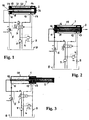
Fig. 1 is a schematic presentation of an unloaded machine in its original state; -
Fig. 2 is a schematic presentation of said machine in the early stage of high-speed splitting; -
Fig. 3 is a schematic presentation of said machine in the final stage of high-speed splitting with; -
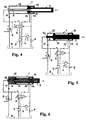
Fig. 4 is a schematic presentation of said machine during performing a reverse stroke upon conclusion of steps according toFigs. 1 to 3 ; -
Fig. 5 is a schematic presentation of said machine in the early stage of high-speed splitting, when the cutting edge abuts a log and the splitting resistance is essentially increased; -
Fig. 6 is a schematic presentation of said machine in the stage of essentially increasing of splitting resistance, upon which splitting is continued with decreased velocity, while the force in the rod is essentially increased; -
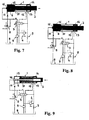
Fig. 7 is a schematic presentation of said machine in the stage immediately prior to overloading i.e. just below the top limit of the regular operation; -
Fig. 8 is a schematic presentation of said machine in the stage of overloading; and -
Fig. 9 is a schematic presentation of said machine upon performing steps according toFigs. 5 to 8 and in the stage of returning into the original state thereof. - Appliance according to the invention consists of a
hydraulic cylinder 1 with incorporatedrod 2, which is in accordance withFig. 1 during the active stroke moved toward s the right and during the reverse stroke towards the left. - Said
cylinder 1 consist of anexternal tube 15 as well as ofinternal tube 16, which extends co-axially therewith, and moreover also of a hollow cup i.e. ahead 14, which actually presents a hollow extension of the active working volume of thecylinder 1 in the longitudinal direction thereof, more precisely in the direction of the active stroke of therod 2. A single-waynonreturn valve 6 is mounted within theinternal tube 16 of thecylinder 1, which enables hydraulic media to flow from the exterior towards the interior and not also from the interior of thetube 16 towards the exterior thereof into the intermediate space between thetubes cylinder 1. - A
rod 2 is available within said intermediate space between saidtubes cylinder 1; said rod2 is hollow and is movable throughout saidhollow head 14 of thecylinder 1 and at the same time along theinternal tube 16, which is actually surrounded by saidrod 2. In addition, therod 2 comprises anoutlet 21, which in the original state of therod 2 coincides with thenonreturn valve 6 within theinternal tube 16 of thecylinder 1. - Said
rod 2 is furthermore equipped with asealing portion 23, which is characterized by greater diameter and is available between theexternal tube 15 and theinternal tube 16 of thecylinder 1 on the side i.e. in the direction of the reverse stroke thereof, as well as with a guidingportion 22, which surrounds theinternal tube 16 of thecylinder 1 at appropriate distance and may be moved throughout saidhead 14 of thecylinder 1, and moreover also with afront portion 24, which protrudes outwards from thecylinder 1 in a direction of the active stroke of therod 2. - Said
cylinder 1 comprises threehydraulic connections first connection 11 is available on theexternal tube 15 of the end portion of thecylinder 1 in the area of reverse stroke of therod 2, namely at a certain distance apart from thesealing portion 23 of therod 2. Thesecond connection 12 is also available on theexternal tube 15, however on the opposite end portion of thecylinder 1, while thethird connection 13 is available in the area of thehead 14 adjacent to saidsecond connection 12. The interior of theinternal tube 16 may also be included into appropriate hydraulic circuit. - In addition to said
cylinder 1 androd 2, said appliance also includes areservoir 8 for storage of each desired hydraulic media, apump 7 for establishing a required pressure of said hydraulic media, and moreover also - a two-way
differential valve 5, which is hydraulically interconnected with thefirst connection 11 and thereservoir 8 and is shifted from one position into another on the basis of achieving of a pre-set value of the pressure, - a
control valve 3, which is in this shown embodiment equipped and switched either by appropriate lever 31 or also by means of the pressure in the thirdhydraulic connection 13, and is hydraulically interconnected either with the interior of theinternal tube 16 of thecylinder 1 and/or with thepump 7 and via saidpump 7 with thereservoir 8 and/or directly with saidreservoir 8 and/or indirectly via asecurity valve 4 and a pressure-regulatingvalve 9 with thereservoir 8; and - s
security valve 6, which is in a parallel manner interconnected between the hydraulic conduit, by means of which thecontrol valve 3 is via saidpump 7 connected with thereservoir 8, and the hydraulic conduit, by means of which thethird connection 13 on thehead 14 of thecylinder 1 is connected with thereservoir 8 via said pressure-regulatingvalve 9. - In
Fig. 1 therod 2 is shown in its original position prior to splitting. Thecylinder 1 is unloaded, and the hydraulic media is fed throughout thecontrol valve 3 into thecylinder 1 and further towards the interior of theinternal tube 16 and towards the secondhydraulic connection 12, through which said media is then returned back to thereservoir 8. The minimum pressure p0 is present in the complete system i.e. inside of theinternal tube 16, in the hollow area of therod 2 and within the intermediate space between therod 2 and theexternal tube 15 of the cylinder. - Upon shifting the lever 31 of the
control valve 3 is displaced in its alternative position (Fig. 2 ), upon which the hydraulic media is directed into the interior of theinternal tube 16 of thecylinder 1, upon which therod 2 is moved with the operating speed towards the right, by which the operating stroke is performed, and by which equilibration of pressure then occurs in the area behind therod 2 via thedifferential valve 5 and thereservoir 8. Thesecurity valve 4 is switched-off, while thepump 7 is operating under the working pressure p1, while in the other sestions of the hydraulic system the pressure p0 is still maintained. - Despite to certain resistance, which normally occurs by splitting the log, the
rod 2 may continue its movement with unchanged velocity towards the end position of the operating stroke (Fig. 3 ), whenever said resistance and consequently also adequate increasing of pressure is not very high. In this, hydraulic media then enters into the interior of thecup 14 and flows throughout thethird connection 13 into appropriate hydraulic conduit, whereupon it is directed towards thecontrol valve 3, which may be shifted i.e. switched, when appropriate. From that state the hydraulic media under the working pressure p1 starts wlowing throughout thesecond connection 12 into the intermediate space, which is limited by therod 2, namely its portion on the side of the active stroke, as well as theinternal tube 16 and theexternal tube 15 of the cylinder, in which due to reduced active surface area the velocity of therod 2 may be essentially higher. During such recerse stroke, the pressure equilibration in the front of therod 2 is performed via thedifferential valve 3 into thereservoir 8. - Whenever by movement of the rod apart from its origin position the resistance is essentially increased, the pressure of the hydraulic media inside of the
internal tube 16 and therod 2 is adequately increased, and simultaneously the speed of therod 2 is decreased (Fig. 5 ). - As soon as the pressure is increased above the pre-set value p2 (
Fig. 6 ), thedifferential valve 5 is shifted to alternative position, which enables hydraulic media to flow from thepump 7 throughout thefirst connection 11 into thecylinder 1, whereupon the complete rear surface of therod 2, which is faced towards the reverse stroke, is exposed to the working pressure p1, through which consequently the pushing force on therod 2 is then essentially increased. - By further increasing of the pressure within the
cylinder 1 behind therod 2 and within therod 2 and theinternal tube 16 of thecylinder 1 up to the highest still allowed value (Fig. 7 ), the hydraulic media under the pressure pmax is flowing from thepump 7 into thecylinder 1 throughout thedifferential valve 5 and thefirst connection 11. - In such state then the
security valve 4 is activated (Fig. 8 ), upon which then the branch of the hydraulic circuit via thesecurity valve 4 is redirected by switching thecontrol valve 3, while thedifferential valve 5 is retained in its current position. - Upon switching the
control valve 3 the hydraulic media from thepump 7 is redirected towards thesecond connection 12 of the cylinder, upon which the hydraulic media is fed into the space among therod 2, namely the side of the active stroke thereof, and bothtubes cylinder 1. Then thedifferential valve 5 is returned into its origin position and the reverse stroke of therod 2 is performed, where the pressure equilibration of thecylinder 1 on the side of the reverse stroke is established via thecontrol valve 3 and thereservoir 8. - Said steps also clearly define a method of controlling of a firewood splitting machine, which is performed by means of said unit according to the invention, wherein the active stroke of the
rod 2 is performed with realtively high velocity, if the splitting resistance does not result in increasing of the pressure within the hydraulic circuit above a predetermined value, and wherein the reverse stroke of therod 2 is performed, during which the velocity of the rod is higher than the previously mentioned velocity during athe normal active stroke; and wherein any occurance of an extreme splitting resistance results in increasing of the pressure of the hydraulic media above the predetermined value, upon which due to activation of thedifferential valve 5 velocity of therod 2 is promptly decreased, where sumultaneously the pushing force in therod 2 is promptly increased. Whenever by such slow movement of therod 2 with enlarged pushing force the loadings should then exceed the top limits of a regular operation, then thanks to thesecurity valve 4 the unit is prevented against damages by switching thecontrol unit 3, which then allows releasing of unit by decreasing the pressure within the hydraulic system and simultaneously performing of the reverse stroke of therod 2.
Claims (7)
- Driving and control unit of a firewood splitting machine, comprising a hydraulic cylinder (1) and a rod (2), which is connected with the pushing means or appropriate blade, which is then by means of said rod (2) pushed towards the log, which is to be splitted, wherein said cylinder (1) is via appropriate connections (11, 12) connected with a corresponding hydraulic circuit, which contains a hydraulic media under a desired pressure, which is supplied from a reservoir (8) by means of a pump (7), said unit comprising a hydraulic cylinder (1), which consists of an external tube (15) having a larger diameter and an internal tube (16) having a smaller diameter and moreover of a head (14), which forms a supplemental chamber in the axial direction of the cylinder (1) on the side of the active stroke of the rod (2), and wherein said cylinder (1) is equipped with three hydraulic connections (11, 12, 13), characterized by, said internal tube (16) is equipped with a nonreturn valve (6), which allows the hydraulic media to flow into the tube (16) and not outwards from it into the intermediate space between the tubes (15, 16) of the cylinder (1) and the hollow rod (2), which is arranged within said intermediate space between said tubes (15, 16) surrounding thereby the internal tube (16) and is moved oscillatory to and fro along said internal tube (16) of the cylinder (1) and also throughout the head (14) of the cylinder (1), and wherein said rod (2) comprises an outlet (21), which in the original position of the rod (2) coincides with the nonreturn valve (6) on the internal wall (16), and further comprises a sealing portion (23), which has a larger diameter and is arranged between the external tube (15) and the internal tube (16) of the cylinder (1), as well as a guiding portion (22) of a smaller diameter, which surrounds at a desired distance said internal tube (16) of the cylinder (1) and is moved throughout said head (14) of the cylinder (1), and also a front portion (24), which protrudes outside of the cylinder (1) in the direction of the active stroke of the rod (2), and wherein said connections (11, 12, 13) of the cylinder (1) are arranged in such a manner, that the first connection (11) is available on the external tube (15) on the end portion of the cylinder (1) in the direction of the reverse stroke of the rod (2) and at appropriate distance apart from the sealing portion (23) of the rod (2), and that the second connection (12) is available on the external tube (15) on the opposite end portion of the cylinder (1) apart from the head (14), and that the third connection (13) is available in the area of said head (14) adjacent to said second connection (12), and wherein by means of these connections (11, 12, 13) said cylinder (1) is connected together with the rod (2) into appropriate hydraulic circuit, which moreover includes a reservoir (8) intended for storage of the hydraulic media, a pump (7) intended for establishing of a desired pressure, and moreover also a differential valve (5), which is hydraulically connected with the first connection (11) and the reservoir (8) and is shifted from one to another position when a pre-defined value of the pressure (p2) is achieved, a control valve (3), which is shifted either by means of a lever (31) or a similar manually controlled mechanical means or also by means of the pressure of the hydraulic media in the area of the third connection (13) and is thereby hydraulically interconnected with the interior of the internal tube (16) of the cylinder (1) and/or with the pump (7) and either directly via said pump (7) also with the reservoir (8) and/or indirectly via the security valve (4) and the pressure-regulating valve (9) with the reservoir (8) and/or with reservoir (8) and the second connection (12), and where said hydraulic circuit also includes a security valve (4), which is connected parallel between the hydraulic conduit, by which the control valve (3) is connected via the pump (7) with the reservoir (8), and the hydraulic circuit, in which the third connection (13) on the head (14) of the cylinder (1) is connected with the reservoir (8) via the pressure-regulating valve (9).
- Unit according to Claim 1, characterized in that the cylinder (1) with the belonging rod (2) is included within a hydraulic circuit, which is concieved in such a manner, that by unloaded cylinder (1) prior to starting of active stroke of the rod (2) in the origin position thereof, the hydraulic media is enabled to flow from the pump (7) throughout the control valve (3) into said cylinder (1) and along the interior of the internal tube (16) towards the second connection (12) and outwards through the control valve (3) back to the reservoir (8), and that the pressure within said internal tube (16), within the hollow rod (2) and also within the intermediate space between the rod (2) and the external tube (15) corresponds to the minimum pressure (po).
- Unit according to Claim 1, characterized in that the cylinder (1) with the belonging rod (2) is included within a hydraulic circuit, which is concieved in such a manner, that the control valve (3) is shifted in its alternative position by means of displacement of the belonging lever (31), upon which the hydraulic media is enabled to enter the interior of the internal tube (16) of the cylinder (1), by which the rod (2) is enabled to perform a high-speed active stroke, while the pressure equilibration in the area behind said rod (2) is enabled through the differential valve (5) and the reservoir (8), the security valve (4) is inactive and the pump (7) may operate under the working pressure (p1), which occurs within the interior of the internal tube (16) of the rod (2), while the pressure in other sections still corresponds to the minimum pressure (po).
- Unit according to Claim 1, characterized in that the cylinder (1) with the belonging rod (2) is included within a hydraulic circuit, which is concieved in such a manner, that by operation under a regular splitting resistance and regular working pressure below the pre-set value (p2), the rod (2) is enabled to move with unchanged speed and to reach the end position of the active stroke, where the hydraulic media is allowed to enter into the interior of the head (14) and then throughout the third connection (13) to appropriate hydraulic conduit, in which the pressure-regulating valve (9) is available in order to redirect the flow towards the control valve (3), which is then shifted in order to enable the hydraulic media to enter into the intermediate space between the rod (2) on the side of the active stroke thereof and the internal tube (16) and the external tube (15) of the cylinder, where the speed of the rod is relatively high thanks to relatively small surface thereof.
- Unit according to Claim 1, characterized in that the cylinder (1) with the belonging rod (2) is included within a hydraulic circuit, which is concieved in such a manner, that by essentially increasing of the splitting resistance the working pressure of the hydraulic media within the interior of the internal tube (16) and the rod (2) is essentially increased, which leads to essentially descreasing of the speed of the rod (2) and increasing of the pressure above the pre-set value (p2), upon which the differential valve (5) is switched to its alternative position, which enables the hydraulic media to flow into the cylinder (1) via the pump (7) and the first connection (11), where the complete rear surface of the rod (2), which is faced in a direction of its reverse stroke, is exposed to the working pressure (p1), by which the pushing force in the rod (2) is then essentially increased.
- Unit according to Claim 1, characterized in that the cylinder (1) with the belonging rod (2) is included within a hydraulic circuit, which is concieved in such a manner, that by increasing of the splitting resistance the working pressure of the hydraulic media behind the rod (2) and within the interior of the internal tube (16) and the rod (2) is increased above the pre-set value (pmax), the hydraulic media under said pressure (pmax) is allowed to flow into the cylinder (1) via the pump (7) and the differential valve (5) and the first connection (11), by which the security valve (4) is activated, while flowing of the hydraulic media throughout said security valve (4) results in shifting of the control valve (3) in its alternative position, while the position of the differential valve (5) remains unchanged.
- Unit according to Claim 1, characterized in that the cylinder (1) with the belonging rod (2) is included within a hydraulic circuit, which is concieved in such a manner, that by shifting of the control valve (3) upon achieving of critical pressure (pmax) the hydraulic media is redirected from the pump (7) towards the second connection (12) of the cylinder (1), upon which the hydraullic media is enabled to enter into the space among the operation stroke faced side of the rod (2) and both tubes (15, 16) of the cylinder (1), which is followed by returning of the differential valve (5) in its origin position and movement of the rod (2) in the direction of the reverse stroke, while the pressure equilibration in the cylinder (1) on the side of the reverse stroke of the rod (2) is achieved via the control valve (3) and the reservoir (8).
Applications Claiming Priority (2)
| Application Number | Priority Date | Filing Date | Title |
|---|---|---|---|
| SI200500164A SI22050B (en) | 2005-06-01 | 2005-06-01 | Driving and controlling unit of device for splitting firewood and controlling procedure for this kind of device |
| PCT/SI2006/000015 WO2006130120A1 (en) | 2005-06-01 | 2006-04-18 | Driving and control unit of a firewood splitting machine and method of controlling such machine |
Publications (2)
| Publication Number | Publication Date |
|---|---|
| EP1886027A1 EP1886027A1 (en) | 2008-02-13 |
| EP1886027B1 true EP1886027B1 (en) | 2008-12-10 |
Family
ID=36609587
Family Applications (1)
| Application Number | Title | Priority Date | Filing Date |
|---|---|---|---|
| EP06733572A Expired - Lifetime EP1886027B1 (en) | 2005-06-01 | 2006-04-18 | Driving and control unit of a firewood splitting machine and method of controlling such machine |
Country Status (6)
| Country | Link |
|---|---|
| EP (1) | EP1886027B1 (en) |
| AT (1) | ATE417206T1 (en) |
| DE (1) | DE602006004207D1 (en) |
| DK (1) | DK1886027T3 (en) |
| SI (1) | SI22050B (en) |
| WO (1) | WO2006130120A1 (en) |
Cited By (1)
| Publication number | Priority date | Publication date | Assignee | Title |
|---|---|---|---|---|
| US11370147B2 (en) | 2017-04-18 | 2022-06-28 | Tajfun Planina Proizvodnja Strojev D.O.O. | Platform with an autonomous powering engine for mounting onto a firewood splitting apparatus |
Families Citing this family (1)
| Publication number | Priority date | Publication date | Assignee | Title |
|---|---|---|---|---|
| CN102678654A (en) * | 2012-06-02 | 2012-09-19 | 山西高行液压股份有限公司 | Variable-speed oil cylinder system |
Family Cites Families (4)
| Publication number | Priority date | Publication date | Assignee | Title |
|---|---|---|---|---|
| FR1439211A (en) * | 1965-04-08 | 1966-05-20 | New hydraulic cylinder for closing mechanism of injection molding machines for plastics and the like | |
| FR2739149B1 (en) * | 1995-09-25 | 1998-01-02 | Dk Le Guen Et Hemidy | QUADRUPLE EFFECT HYDRAULIC CYLINDER |
| DE19747298A1 (en) * | 1997-10-25 | 1999-04-29 | Nimak Automatisierte Schweiste | Welding gun cylinder |
| IT1319478B1 (en) * | 2000-12-05 | 2003-10-10 | Bell Srl | HYDRAULIC GROUP WITH AUTOMATIC REGENERATIVE SYSTEM TYPICALLY FOR WOOD SPLITTERS OPERATED BY A SINGLE-ACTING JACK |
-
2005
- 2005-06-01 SI SI200500164A patent/SI22050B/en active Search and Examination
-
2006
- 2006-04-18 DE DE602006004207T patent/DE602006004207D1/en not_active Expired - Lifetime
- 2006-04-18 AT AT06733572T patent/ATE417206T1/en active
- 2006-04-18 DK DK06733572T patent/DK1886027T3/en active
- 2006-04-18 WO PCT/SI2006/000015 patent/WO2006130120A1/en not_active Ceased
- 2006-04-18 EP EP06733572A patent/EP1886027B1/en not_active Expired - Lifetime
Cited By (1)
| Publication number | Priority date | Publication date | Assignee | Title |
|---|---|---|---|---|
| US11370147B2 (en) | 2017-04-18 | 2022-06-28 | Tajfun Planina Proizvodnja Strojev D.O.O. | Platform with an autonomous powering engine for mounting onto a firewood splitting apparatus |
Also Published As
| Publication number | Publication date |
|---|---|
| SI22050B (en) | 2009-04-30 |
| ATE417206T1 (en) | 2008-12-15 |
| SI22050A (en) | 2006-12-31 |
| DK1886027T3 (en) | 2009-04-06 |
| EP1886027A1 (en) | 2008-02-13 |
| DE602006004207D1 (en) | 2009-01-22 |
| WO2006130120A1 (en) | 2006-12-07 |
Similar Documents
| Publication | Publication Date | Title |
|---|---|---|
| EP1925825B1 (en) | Relief pressure switching apparatus for hydraulic working machine | |
| EP1662151B1 (en) | Hydraulic drive apparatus | |
| EP1809852B1 (en) | Hydraulic impact mechanism | |
| US4590763A (en) | Method of supplying a normally continuous operating hydraulic actuator with hydraulic fluid, continuously and by controlled pulse, and a device for implementing said method | |
| US4834461A (en) | Control system for a multiple shank impact ripper | |
| EP1886027B1 (en) | Driving and control unit of a firewood splitting machine and method of controlling such machine | |
| NO325468B1 (en) | shock device | |
| EP2264322B1 (en) | Pressurized-medium system and pressurized-medium component as well as a hydraulic splitter | |
| AU2019247732A1 (en) | Hydraulic actuator, working device, and energy-wood grapple | |
| US2795933A (en) | Hydraulic circuit for cutoff device or the like | |
| EP1712336B1 (en) | Splitting machine for wood pieces | |
| SE429111B (en) | HYDRAULIC DRIVES | |
| JPS5973251A (en) | Auxiliary clamping device for steel pipe cutting machine | |
| JP2000145717A (en) | Hydraulic cylinder control device for construction machine | |
| EP0855468A1 (en) | Roller-crusher | |
| JP2010071441A (en) | Boost type cylinder apparatus | |
| JP3281594B2 (en) | Vibration type hydraulic cylinder device for construction work machine | |
| SU665860A2 (en) | Hydraulic drive of cutting unit of foresting machine | |
| JPH06272400A (en) | Crushing device | |
| JP4818758B2 (en) | Mast rattle prevention device | |
| KR101250083B1 (en) | Hydraulic control apparatus for a log loader excavator | |
| JP4058727B2 (en) | Hydraulic supply device to hydraulic cylinder for correction of buried pipe propulsion direction correction device | |
| CA2392648A1 (en) | Method and apparatus for removing thimbles from the stubs of an anode | |
| SU1090292A1 (en) | Hydraulic drive of gripping and cutting device | |
| JPH0559751A (en) | Hydraulic operating circuit |
Legal Events
| Date | Code | Title | Description |
|---|---|---|---|
| PUAI | Public reference made under article 153(3) epc to a published international application that has entered the european phase |
Free format text: ORIGINAL CODE: 0009012 |
|
| 17P | Request for examination filed |
Effective date: 20061206 |
|
| AK | Designated contracting states |
Kind code of ref document: A1 Designated state(s): AT BE BG CH CY CZ DE DK EE ES FI FR GB GR HU IE IS IT LI LT LU LV MC NL PL PT RO SE SI SK TR |
|
| GRAP | Despatch of communication of intention to grant a patent |
Free format text: ORIGINAL CODE: EPIDOSNIGR1 |
|
| DAX | Request for extension of the european patent (deleted) | ||
| GRAS | Grant fee paid |
Free format text: ORIGINAL CODE: EPIDOSNIGR3 |
|
| GRAS | Grant fee paid |
Free format text: ORIGINAL CODE: EPIDOSNIGR3 |
|
| GRAA | (expected) grant |
Free format text: ORIGINAL CODE: 0009210 |
|
| AK | Designated contracting states |
Kind code of ref document: B1 Designated state(s): AT BE BG CH CY CZ DE DK EE ES FI FR GB GR HU IE IS IT LI LT LU LV MC NL PL PT RO SE SI SK TR |
|
| REG | Reference to a national code |
Ref country code: GB Ref legal event code: FG4D |
|
| REG | Reference to a national code |
Ref country code: CH Ref legal event code: EP |
|
| REG | Reference to a national code |
Ref country code: IE Ref legal event code: FG4D |
|
| REF | Corresponds to: |
Ref document number: 602006004207 Country of ref document: DE Date of ref document: 20090122 Kind code of ref document: P |
|
| REG | Reference to a national code |
Ref country code: CH Ref legal event code: NV Representative=s name: PATENTANWALTSBUERO ZINK |
|
| REG | Reference to a national code |
Ref country code: SE Ref legal event code: TRGR |
|
| REG | Reference to a national code |
Ref country code: DK Ref legal event code: T3 |
|
| PG25 | Lapsed in a contracting state [announced via postgrant information from national office to epo] |
Ref country code: LT Free format text: LAPSE BECAUSE OF FAILURE TO SUBMIT A TRANSLATION OF THE DESCRIPTION OR TO PAY THE FEE WITHIN THE PRESCRIBED TIME-LIMIT Effective date: 20081210 |
|
| PG25 | Lapsed in a contracting state [announced via postgrant information from national office to epo] |
Ref country code: SI Free format text: LAPSE BECAUSE OF FAILURE TO SUBMIT A TRANSLATION OF THE DESCRIPTION OR TO PAY THE FEE WITHIN THE PRESCRIBED TIME-LIMIT Effective date: 20081210 Ref country code: PL Free format text: LAPSE BECAUSE OF FAILURE TO SUBMIT A TRANSLATION OF THE DESCRIPTION OR TO PAY THE FEE WITHIN THE PRESCRIBED TIME-LIMIT Effective date: 20081210 Ref country code: LV Free format text: LAPSE BECAUSE OF FAILURE TO SUBMIT A TRANSLATION OF THE DESCRIPTION OR TO PAY THE FEE WITHIN THE PRESCRIBED TIME-LIMIT Effective date: 20081210 Ref country code: FI Free format text: LAPSE BECAUSE OF FAILURE TO SUBMIT A TRANSLATION OF THE DESCRIPTION OR TO PAY THE FEE WITHIN THE PRESCRIBED TIME-LIMIT Effective date: 20081210 Ref country code: NL Free format text: LAPSE BECAUSE OF FAILURE TO SUBMIT A TRANSLATION OF THE DESCRIPTION OR TO PAY THE FEE WITHIN THE PRESCRIBED TIME-LIMIT Effective date: 20081210 |
|
| NLV1 | Nl: lapsed or annulled due to failure to fulfill the requirements of art. 29p and 29m of the patents act | ||
| PG25 | Lapsed in a contracting state [announced via postgrant information from national office to epo] |
Ref country code: RO Free format text: LAPSE BECAUSE OF FAILURE TO SUBMIT A TRANSLATION OF THE DESCRIPTION OR TO PAY THE FEE WITHIN THE PRESCRIBED TIME-LIMIT Effective date: 20081210 Ref country code: EE Free format text: LAPSE BECAUSE OF FAILURE TO SUBMIT A TRANSLATION OF THE DESCRIPTION OR TO PAY THE FEE WITHIN THE PRESCRIBED TIME-LIMIT Effective date: 20081210 Ref country code: ES Free format text: LAPSE BECAUSE OF FAILURE TO SUBMIT A TRANSLATION OF THE DESCRIPTION OR TO PAY THE FEE WITHIN THE PRESCRIBED TIME-LIMIT Effective date: 20090321 |
|
| PG25 | Lapsed in a contracting state [announced via postgrant information from national office to epo] |
Ref country code: PT Free format text: LAPSE BECAUSE OF FAILURE TO SUBMIT A TRANSLATION OF THE DESCRIPTION OR TO PAY THE FEE WITHIN THE PRESCRIBED TIME-LIMIT Effective date: 20090511 Ref country code: CZ Free format text: LAPSE BECAUSE OF FAILURE TO SUBMIT A TRANSLATION OF THE DESCRIPTION OR TO PAY THE FEE WITHIN THE PRESCRIBED TIME-LIMIT Effective date: 20081210 Ref country code: IS Free format text: LAPSE BECAUSE OF FAILURE TO SUBMIT A TRANSLATION OF THE DESCRIPTION OR TO PAY THE FEE WITHIN THE PRESCRIBED TIME-LIMIT Effective date: 20090410 |
|
| PG25 | Lapsed in a contracting state [announced via postgrant information from national office to epo] |
Ref country code: SK Free format text: LAPSE BECAUSE OF FAILURE TO SUBMIT A TRANSLATION OF THE DESCRIPTION OR TO PAY THE FEE WITHIN THE PRESCRIBED TIME-LIMIT Effective date: 20081210 |
|
| PLBE | No opposition filed within time limit |
Free format text: ORIGINAL CODE: 0009261 |
|
| STAA | Information on the status of an ep patent application or granted ep patent |
Free format text: STATUS: NO OPPOSITION FILED WITHIN TIME LIMIT |
|
| 26N | No opposition filed |
Effective date: 20090911 |
|
| REG | Reference to a national code |
Ref country code: IE Ref legal event code: MM4A |
|
| PG25 | Lapsed in a contracting state [announced via postgrant information from national office to epo] |
Ref country code: MC Free format text: LAPSE BECAUSE OF NON-PAYMENT OF DUE FEES Effective date: 20090430 Ref country code: IE Free format text: LAPSE BECAUSE OF NON-PAYMENT OF DUE FEES Effective date: 20090418 |
|
| PG25 | Lapsed in a contracting state [announced via postgrant information from national office to epo] |
Ref country code: GR Free format text: LAPSE BECAUSE OF FAILURE TO SUBMIT A TRANSLATION OF THE DESCRIPTION OR TO PAY THE FEE WITHIN THE PRESCRIBED TIME-LIMIT Effective date: 20090311 |
|
| PG25 | Lapsed in a contracting state [announced via postgrant information from national office to epo] |
Ref country code: LU Free format text: LAPSE BECAUSE OF NON-PAYMENT OF DUE FEES Effective date: 20090418 |
|
| PG25 | Lapsed in a contracting state [announced via postgrant information from national office to epo] |
Ref country code: HU Free format text: LAPSE BECAUSE OF FAILURE TO SUBMIT A TRANSLATION OF THE DESCRIPTION OR TO PAY THE FEE WITHIN THE PRESCRIBED TIME-LIMIT Effective date: 20090611 |
|
| PG25 | Lapsed in a contracting state [announced via postgrant information from national office to epo] |
Ref country code: TR Free format text: LAPSE BECAUSE OF FAILURE TO SUBMIT A TRANSLATION OF THE DESCRIPTION OR TO PAY THE FEE WITHIN THE PRESCRIBED TIME-LIMIT Effective date: 20081210 |
|
| PG25 | Lapsed in a contracting state [announced via postgrant information from national office to epo] |
Ref country code: CY Free format text: LAPSE BECAUSE OF FAILURE TO SUBMIT A TRANSLATION OF THE DESCRIPTION OR TO PAY THE FEE WITHIN THE PRESCRIBED TIME-LIMIT Effective date: 20081210 |
|
| PGFP | Annual fee paid to national office [announced via postgrant information from national office to epo] |
Ref country code: GB Payment date: 20140326 Year of fee payment: 9 |
|
| PGFP | Annual fee paid to national office [announced via postgrant information from national office to epo] |
Ref country code: BE Payment date: 20140325 Year of fee payment: 9 |
|
| PGFP | Annual fee paid to national office [announced via postgrant information from national office to epo] |
Ref country code: SE Payment date: 20140422 Year of fee payment: 9 Ref country code: BG Payment date: 20140428 Year of fee payment: 9 Ref country code: CH Payment date: 20140429 Year of fee payment: 9 Ref country code: IT Payment date: 20140417 Year of fee payment: 9 |
|
| PGFP | Annual fee paid to national office [announced via postgrant information from national office to epo] |
Ref country code: DK Payment date: 20140410 Year of fee payment: 9 |
|
| REG | Reference to a national code |
Ref country code: DK Ref legal event code: EBP Effective date: 20150430 |
|
| REG | Reference to a national code |
Ref country code: CH Ref legal event code: PL |
|
| REG | Reference to a national code |
Ref country code: SE Ref legal event code: EUG |
|
| GBPC | Gb: european patent ceased through non-payment of renewal fee |
Effective date: 20150418 |
|
| PG25 | Lapsed in a contracting state [announced via postgrant information from national office to epo] |
Ref country code: LI Free format text: LAPSE BECAUSE OF NON-PAYMENT OF DUE FEES Effective date: 20150430 Ref country code: GB Free format text: LAPSE BECAUSE OF NON-PAYMENT OF DUE FEES Effective date: 20150418 Ref country code: IT Free format text: LAPSE BECAUSE OF NON-PAYMENT OF DUE FEES Effective date: 20150418 Ref country code: CH Free format text: LAPSE BECAUSE OF NON-PAYMENT OF DUE FEES Effective date: 20150430 |
|
| PG25 | Lapsed in a contracting state [announced via postgrant information from national office to epo] |
Ref country code: SE Free format text: LAPSE BECAUSE OF NON-PAYMENT OF DUE FEES Effective date: 20150419 |
|
| REG | Reference to a national code |
Ref country code: FR Ref legal event code: PLFP Year of fee payment: 11 |
|
| PG25 | Lapsed in a contracting state [announced via postgrant information from national office to epo] |
Ref country code: DK Free format text: LAPSE BECAUSE OF NON-PAYMENT OF DUE FEES Effective date: 20150430 Ref country code: BG Free format text: LAPSE BECAUSE OF NON-PAYMENT OF DUE FEES Effective date: 20160331 |
|
| PG25 | Lapsed in a contracting state [announced via postgrant information from national office to epo] |
Ref country code: BE Free format text: LAPSE BECAUSE OF NON-PAYMENT OF DUE FEES Effective date: 20150430 |
|
| REG | Reference to a national code |
Ref country code: FR Ref legal event code: PLFP Year of fee payment: 12 |
|
| REG | Reference to a national code |
Ref country code: FR Ref legal event code: PLFP Year of fee payment: 13 |
|
| PGFP | Annual fee paid to national office [announced via postgrant information from national office to epo] |
Ref country code: FR Payment date: 20250324 Year of fee payment: 20 |
|
| PGFP | Annual fee paid to national office [announced via postgrant information from national office to epo] |
Ref country code: DE Payment date: 20250324 Year of fee payment: 20 |
|
| PGFP | Annual fee paid to national office [announced via postgrant information from national office to epo] |
Ref country code: AT Payment date: 20250325 Year of fee payment: 20 |
|
| REG | Reference to a national code |
Ref country code: DE Ref legal event code: R071 Ref document number: 602006004207 Country of ref document: DE |