EP1884684A2 - Transmission system for transforming a rotary movement into a linear movement - Google Patents
Transmission system for transforming a rotary movement into a linear movement Download PDFInfo
- Publication number
- EP1884684A2 EP1884684A2 EP07013355A EP07013355A EP1884684A2 EP 1884684 A2 EP1884684 A2 EP 1884684A2 EP 07013355 A EP07013355 A EP 07013355A EP 07013355 A EP07013355 A EP 07013355A EP 1884684 A2 EP1884684 A2 EP 1884684A2
- Authority
- EP
- European Patent Office
- Prior art keywords
- nut
- threaded spindle
- bearing
- thread
- transmission according
- Prior art date
- Legal status (The legal status is an assumption and is not a legal conclusion. Google has not performed a legal analysis and makes no representation as to the accuracy of the status listed.)
- Granted
Links
Images


Classifications
-
- F—MECHANICAL ENGINEERING; LIGHTING; HEATING; WEAPONS; BLASTING
- F16—ENGINEERING ELEMENTS AND UNITS; GENERAL MEASURES FOR PRODUCING AND MAINTAINING EFFECTIVE FUNCTIONING OF MACHINES OR INSTALLATIONS; THERMAL INSULATION IN GENERAL
- F16H—GEARING
- F16H25/00—Gearings comprising primarily only cams, cam-followers and screw-and-nut mechanisms
- F16H25/18—Gearings comprising primarily only cams, cam-followers and screw-and-nut mechanisms for conveying or interconverting oscillating or reciprocating motions
- F16H25/20—Screw mechanisms
- F16H25/22—Screw mechanisms with balls, rollers, or similar members between the co-operating parts; Elements essential to the use of such members
- F16H25/2285—Screw mechanisms with balls, rollers, or similar members between the co-operating parts; Elements essential to the use of such members with rings engaging the screw shaft with the inner perimeter, e.g. using inner rings of a ball bearing
- F16H25/229—Eccentric rings with their axis arranged substantially parallel to the screw shaft axis
Definitions
- the invention relates to a transmission for converting a rotational movement into a linear movement with a threaded spindle, at least one rolling bearing, a bearing housing and an axially parallel and eccentric threaded spindle mounted provided with at least one thread whose thread has no pitch and at least partially into the thread groove of Threaded spindle engages.
- Gear for converting a rotational movement into a linear movement are also referred to in technical language as a helical gear, Wälzschraubgetriebe or Wälzringspindelgetriebe. These transmissions are often performed with two or more bearings and the corresponding Wälzlageragen.
- a Wälzringspindeltrieb which consists of a work spindle, a roller bearing and a driven housing.
- a rolling bearing As a transfer element between the threaded spindle and the output housing is a rolling bearing.
- this Wälzringspindeltrieb a Wälzring which engages in the thread groove of the threaded spindle.
- the special feature is that the rolling bearing is arranged eccentrically to the longitudinal axis of the threaded spindle, wherein the central axis of the rolling bearing is inclined relative to this.
- a rolling bearing receptacle is furthermore arranged, which receives the roller bearings, so that an axial force to be transmitted is transmitted from the threaded spindle via the roller bearing into the roller bearing receiving body and then to the housing.
- This roller bearing receiving body is in turn arranged rotationally symmetrical to the longitudinal axis of the threaded spindle.
- the Wälzring is provided with a semicircular curved profile, which corresponds to the correspondingly shaped profile of the thread of the threaded spindle, thus to realize a rolling process in the groove of the thread of the threaded spindle.
- both the thread groove of the engaging in the threaded spindle Wälzringes and the threaded groove of the threaded spindle are provided with a radius of curvature, wherein the radius of curvature of engaging in the threaded groove of the threaded roller ring depending on the radius of curvature of the thread groove to choose is.
- the production of these radii of curvature are very costly and time consuming.
- rolling bearings are provided on both sides at the end of WälzlagerageMechs.
- the axially and radially acting forces on the rolling ring are taken up by a bearing introduced between its circumference and driven housing, in this case a thrust bearing designed as a ball bearing.
- the bearing of the Wälzrings is realized by means of at least one deep groove ball bearings, since they are suitable to be able to absorb both axial and radial forces.
- this transmission consists of at least one roller bearing, a bearing housing and an axially parallel and eccentric to the threaded spindle mounted, provided with at least one thread nut.
- the thread of the nut has no pitch and engages at least partially in the thread groove of the threaded spindle.
- both the thread flank of the threaded spindle and the thread flanks of the nut have the same flank angle and are not curved at least on the axial force transmitting side.
- the nut has a plurality of threads designated as grooves, wherein the distance between two successive grooves corresponds to the thread pitch of the threaded spindle.
- the bearing of the nut is effected by at least one radial needle bearing. By choosing this bearing the required space can be significantly reduced.
- the threaded spindle is mounted by both sides arranged on the front side of the nut roller bearings. These can also be designed for reasons of space as axial needle roller bearings.
- This transmission has a threaded spindle 1 with a corresponding thread pitch p1, for example of 1.5 mm, which is enveloped by a nut 2.
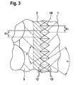
- the nut 2 is provided with a correspondingly larger inner diameter than the outer diameter of the threaded spindle 1 and has in this embodiment, a plurality of threads 14 (Fig. 3), wherein each thread 14 has a threaded wedge.
- Fig. 3 a plurality of threads 14
- only one thread 14 can be introduced for the fulfillment of the function in the nut 2. It is important that these threads 14 have no slope, whereby they can also be referred to as grooves.
- the nut 2 is arranged eccentrically to the axis 9 of the threaded spindle 1. Its axis is parallel to the axis 9 of the threaded spindle 1 and is located at a distance to this, which results in that, as is apparent from the sectional view of Figure 1, the profile of the nut 2, so the threaded wedges, on the right side of the threaded spindle 1 in the thread profile, here the thread base, contacted and on the left side no contact exists.
- This engagement of threaded wedge of the nut 2 in the thread root of the threaded spindle 1 is only possible with equal flank angles of the profiles of threaded spindle 1 and nut 2. Due to the rotation of the threaded spindle 1 about its axis 9, the nut 2 must rotate about its axis 10, because it touches the threaded spindle 1 at a circumferential location and rolls on the circumference.
- the nut 2 rotates due to the frictional engagement due to the contact - Flank Thread wedge Threaded spindle 1 with flank Thread wedge Nut 2 - with.
- the pitch p1 of the threaded spindle 1 thus causes an axial movement of the nut 2, in this case during a revolution of the threaded spindle 1 of 1.5 mm.
- the introduced axial force is based on the wedge of the thread at the point of contact of nut 2 and threaded spindle 1, whereby the introduced axial force receives a radial component, which must be absorbed by the bearing of the threaded spindle 1.
- the outer ring 4 of the Abstützlagers 11 are set in a rotational movement about the axis 10.
- the lowest point of engagement of the two wedges, which are formed by the angle moves around the threaded spindle 1.
- the resulting radial support force thereby also migrates.
- the axis 9 of the threaded spindle 1 must be performed. For this purpose, it is guided in the radial bearings 7.
- FIG. 2 shows the structure of a transmission according to the invention in a perspective view according to Figure 1.
- the bearing housing is recognizable, which is arranged on the threaded spindle 1.
- FIG. 3 shows a detail left of the axis 9 from FIG. 1, where the two thread flanks 12, 13 of the threaded spindle 1 and nut 2 do not touch.
- the profiles of the two contacting components are shown enlarged for better understanding, so that the flank angles ⁇ and ⁇ of the thread flanks 12 and 13 of threaded spindle 1 and nut 2 and the groove pitch p2 of the nut 2 and the pitch p1 of the threaded spindle 1 clearly are recognizable.
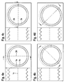
- the plan view of the cutting plane 24 is visible and in the left half are on both sides of the axis 1 c of the threaded spindle 1, the contact points or contact surfaces of both components visible.
- the sectional plane 24 is located in the figure 4a at an angle of 0 °.
- the cutting plane 24 is at an angle of 45 °; in the figure 4c at an angle of 90 ° and finally in the figure 4d at an angle of 135 °.
- This radial needle bearing 15 serves to absorb the radial forces occurring and to decouple the rotational movement of the motor rotor 19 from the nut rotational movement.
- To accommodate the axial forces of the threaded spindle 1 are on both sides of the front side of the nut second Axial needle bearing 16 provided as a rolling bearing. These axial forces are introduced into the motor rotor 19 of the electric motor 23 and passed on from this further via a rotor bearing 18 to the housing 17 of the electric motor 23.
- Both the axial needle bearing 16 and the rotor bearing 18, which is also a roller bearing, thereby have to transmit the full axial force whose direction is indicated by the arrow.
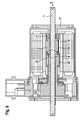
- FIG. 6 once again shows the transmission according to the invention used in the electric motor 23 according to FIG.
- the nut 2, the radial needle bearing 15, the threaded spindle 1, the motor rotor 19 and the housing 17 of the electric motor 23 are arranged in principle in the same place.
- this variant has an altered axial bearing of the nut 2.
- the initiated by the threaded spindle 1 in the nut 2 axial component is not introduced via a roller bearing 16 in the rotor 19 and from there via a rotor bearing 18 in the housing 17, but only via a plain bearing directly into the housing 17.
- This is created by the Crescent-shaped contact region 20 between the nut 2 and housing 17.
- this section A is explained later in Figure 7 in more detail.
- the rotor bearings 21 and 22 can be dimensioned correspondingly smaller due to the lack of axial force and the two axial needle roller bearings 16 can be omitted.
- This variant of the storage has the consequence that the transmission can be made smaller and thus can be used for smaller spaces and also the production costs can be reduced.
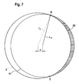
- FIG. 7 shows the sliding bearing surface according to FIG. 6 which adjusts in the contact region 20. This is shown hatched.
- the point B denotes the beginning and the point C the end of the crescent-shaped surface.
- these two places B and C mean that at the point B, the contact between nut 2 and housing 17 occurs, continues over the shaded area, each component has its own fulcrum and they have a distance e each other, in terms of area to reach of a maximum increases steadily to decrease again until it ends at the point C.
- the radius r17 of the housing 17 forms the outer boundary and the radius r2 of the nut forms the inner boundary of the hatched area. From this figure also shows the relationship between efficiency and load capacity. A smaller area indicates better efficiency due to less drilling friction, but with higher surface pressure. As the area increases, the area decreases Surface pressure. This in turn increases the carrying capacity and also the service life.
Abstract
Description
Die Erfindung betrifft ein Getriebe zur Umwandlung einer Drehbewegung in eine Linearbewegung mit einer Gewindespindel, mindestens einem Wälzlager, einem Lagergehäuse und einer achsparallel und exzentrisch zur Gewindespindel gelagerten mit mindestens einem Gewindegang versehenen Mutter, deren Gewindegang keine Steigung aufweist und der zumindest teilweise in die Gewindenut der Gewindespindel eingreift.The invention relates to a transmission for converting a rotational movement into a linear movement with a threaded spindle, at least one rolling bearing, a bearing housing and an axially parallel and eccentric threaded spindle mounted provided with at least one thread whose thread has no pitch and at least partially into the thread groove of Threaded spindle engages.
Getriebe zur Umwandlung einer Drehbewegung in eine Linearbewegung werden in der Fachsprache auch als Schraubgetriebe, Wälzschraubgetriebe oder auch Wälzringspindelgetriebe bezeichnet. Diese Getriebe werden häufig mit zwei oder mehr Wälzlagern und den dazu entsprechenden Wälzlageraufnahmen geführt.Gear for converting a rotational movement into a linear movement are also referred to in technical language as a helical gear, Wälzschraubgetriebe or Wälzringspindelgetriebe. These transmissions are often performed with two or more bearings and the corresponding Wälzlageraufnahmen.
Aus dem Stand der Technik ist beispielsweise gemäß
Zur Lagerung der Gewindespindel und Aufnahme der Radialkräfte sind beidseitig am Ende des Wälzlageraufnahmekörpers Wälzlager vorgesehen. Die axial und radial wirkenden Kräfte am Wälzring werden von einem zwischen dessen Umfang und Abtriebsgehäuse eingebrachten Lager, in diesem Fall einem als Kugellager ausgebildeten Axiallager, aufgenommen. Die Lagerung des Wälzrings wird mittels mindestens einem Rillenkugellager realisiert, da diese geeignet sind, sowohl Axial- als auch Radialkräfte aufnehmen zu können.For supporting the threaded spindle and receiving the radial forces rolling bearings are provided on both sides at the end of Wälzlageraufnahmekörpers. The axially and radially acting forces on the rolling ring are taken up by a bearing introduced between its circumference and driven housing, in this case a thrust bearing designed as a ball bearing. The bearing of the Wälzrings is realized by means of at least one deep groove ball bearings, since they are suitable to be able to absorb both axial and radial forces.
Soll ein Getriebe dieser Bauart mit einem besonders geringen Spiel zwischen der Gewindespindel und der Mutter verwirklicht werden, so ist darauf zu achten, dass weitestgehend die Spielfreiheit für beide Drehrichtungen der Gewindespindel gewährleistet ist. Dies lässt sich besonders gut realisieren, wenn zwei oder mehr Wälzlager vorgesehen sind.If a transmission of this type is to be realized with a particularly small clearance between the threaded spindle and the nut, then it must be ensured that, as far as possible, the backlash for both directions of rotation of the threaded spindle is ensured. This can be realized particularly well if two or more rolling bearings are provided.
Allerdings treten bei diesem Getriebe Reibungsverluste an den Kraftübertragungs- und Lagerstellen durch die Lagerung auf, so dass der mechanische Wirkungsgrad bei der Umsetzung der Drehbewegung der Gewindespindel in eine Linearbewegung der Mutter zu wünschen übrig lässt.However, in this gear friction losses occur at the power transmission and bearing points due to the storage, so that the mechanical efficiency in the implementation of the rotational movement of the threaded spindle in a linear movement of the mother leaves something to be desired.
Daher ist es Aufgabe der Erfindung, ein Getriebe der vorbenannten Art so auszuführen, dass dessen Wirkungsgrad verbessert wird und gleichzeitig seine Herstellung kostengünstig ist.It is therefore an object of the invention to design a transmission of the aforementioned type so that its efficiency is improved and at the same time its production is cost-effective.
Diese Aufgabe wird mit einem Getriebe gelöst, das die Merkmale nach Anspruch 1 aufweist. Somit besteht dieses Getriebe aus mindestens einem Wälzlager, einem Lagergehäuse und einer achsparallel und exzentrisch zur Gewindespindel gelagerten, mit mindestens einem Gewindegang versehenen Mutter. Der Gewindegang der Mutter weist jedoch keine Steigung auf und greift zumindest teilweise in die Gewindenut der Gewindespindel ein. Dabei weisen sowohl die Gewindeflanke der Gewindespindel als auch die Gewindeflanken der Mutter den gleichen Flankenwinkel auf und sind zumindest auf der Axialkraft übertragenden Seite nicht gekrümmt.This object is achieved with a transmission having the features of
In einer weiteren vorteilhaften Ausgestaltung weist die Mutter mehrere als Rillen bezeichnete Gewindegänge auf, wobei der Abstand zweier aufeinander folgender Rillen der Gewindesteigung der Gewindespindel entspricht. Somit ist ein Kämmen oder Abrollen beider Flanken aufeinander möglich, wobei dabei eine möglichst große Fläche miteinander in Eingriff gelangt.In a further advantageous embodiment, the nut has a plurality of threads designated as grooves, wherein the distance between two successive grooves corresponds to the thread pitch of the threaded spindle. Thus, a combing or unrolling of both flanks is possible, whereby the largest possible surface engages with each other.
Ein Vorteil ist es weiterhin, wenn die Achsen von Gewindespindel und Mutter im Raum parallel zueinander verlaufen.It is also an advantage if the axes of threaded spindle and nut in the space parallel to each other.
Besonders vorteilhaft ist es, wenn die Lagerung der Mutter durch mindestens ein Radial-Nadellager erfolgt. Durch die Wahl dieses Wälzlagers kann der erforderliche Bauraum wesentlich verringert werden.It is particularly advantageous if the bearing of the nut is effected by at least one radial needle bearing. By choosing this bearing the required space can be significantly reduced.
In einer vorteilhaften Ausgestaltung des Getriebes wird die Gewindespindel durch beidseitig an der Stirnseite der Mutter angeordnete Wälzlager gelagert. Diese können ebenfalls aus Platzgründen als Axial-Nadellager ausgeführt sein.In an advantageous embodiment of the transmission, the threaded spindle is mounted by both sides arranged on the front side of the nut roller bearings. These can also be designed for reasons of space as axial needle roller bearings.
Allerdings ist es besonders vorteilhaft unter Ausnutzung des durch Überlagerung der exzentrisch zueinander angeordneten kreisringförmigen Stirnflächen von Mutter und Gehäuse entstehenden und im Betrieb umlaufenden sichelförmigen Kontaktbereichs, diesen Bereich zur Gleitlagerung der Mutter bezüglich der Erzeugung einer Axialkraft zu nutzen. Aus diesem Grunde kann die verbleibende Lagerung aufgrund der fehlenden Axialkraft entsprechend kleiner dimensioniert werden und die Axial-Nadellager können entfallen. Dadurch kann das Getriebe kleiner dimensioniert werden und ist damit für kleinere Werkmaschinen einsetzbar. Außerdem können die Herstellungskosten gesenkt werden.However, it is particularly advantageous to use this area for sliding bearing of the mother with respect to the generation of an axial force by taking advantage of the superimposed by the eccentrically arranged annular faces of nut and housing and circulating in operation crescent-shaped contact area. For this reason, the remaining storage due to the lack of axial force can be dimensioned correspondingly smaller and the axial needle bearings can be omitted. As a result, the gear can be made smaller and is thus suitable for smaller machines. In addition, the manufacturing cost can be reduced.
Weitere Vorteile und vorteilhafte Weiterbildungen der Erfindung sind Gegenstand der nachfolgenden Figuren sowie deren Beschreibungsteile.Further advantages and advantageous developments of the invention are the subject of the following figures and their parts description.
Es zeigen:
Figur 1- den prinzipiellen Aufbau eines erfindungsgemäßen Getriebes zur Umwandlung einer Drehbewegung in eine Linearbewegung in einer Schnittdarstellung,
Figur 2- eine perspektivische Darstellung des erfindungsgemäßen Getriebes gemäß
Figur 1, Figur 3- einen Ausschnitt aus der
Figur 1 in einer Vergrößerung, - Figuren 4a bis 4d
- den gemäß der gewählten Schnittebenen sich ändernden Flächenkontakt zwischen Gewindespindel und Mutter
Figur 5- eine mögliche Anwendung des erfindungsgemäßen Getriebes im Werkzeugmaschinenbereich,
Figur 6- ein Getriebe gemäß
Figur 5 mit einer alternativen bzw. optimierten Lagerung von Gewindespindel und Mutter, Figur 7- die sich im Kontaktbereich zwischen Mutter und Gehäuse ergebende sichelförmige Gleitlagerfläche gemäß
Figur 6
- FIG. 1
- the basic structure of a transmission according to the invention for converting a rotary movement into a linear movement in a sectional view,
- FIG. 2
- 3 a perspective view of the transmission according to the invention according to FIG. 1,
- FIG. 3
- a section of the figure 1 in an enlargement,
- FIGS. 4a to 4d
- the surface contact between the threaded spindle and the nut that changes according to the selected cutting planes
- FIG. 5
- a possible application of the transmission according to the invention in the machine tool sector,
- FIG. 6
- a transmission according to FIG. 5 with an alternative or optimized bearing of threaded spindle and nut,
- FIG. 7
- the crescent-shaped plain bearing surface resulting in the contact area between the nut and the housing according to FIG. 6
Bei der Beschreibung der Figuren 1 bis 7 wurden für gleiche Bauteile die gleichen Bezugszeichen verwendet.In the description of Figures 1 to 7, the same reference numerals have been used for the same components.
Die Figur 1 zeigt den prinzipiellen Aufbau eines Getriebes zur Umwandlung einer Drehbewegung in eine Linearbewegung in einer Schnittdarstellung. Dieses erfindungsgemäße Getriebe weist eine Gewindespindel 1 mit einer entsprechenden Gewindesteigung p1, beispielsweise von 1,5 mm auf, die von einer Mutter 2 umhüllt wird. Die Mutter 2 ist dabei mit einem entsprechend größeren Innendurchmesser als dem Außendurchmesser der Gewindespindel 1 versehen und weist in diesem Ausführungsbeispiel mehrere Gewindegänge 14 (Fig. 3) auf, wobei jeder Gewindegang 14 einen Gewindekeil besitzt. Allerdings kann für die Erfüllung der Funktion in die Mutter 2 auch nur ein Gewindegang 14 eingebracht sein. Wichtig dabei ist, dass diese Gewindegänge 14 keine Steigung haben, wodurch diese auch als Rillen bezeichnet werden können. Weiterhin ist die Mutter 2 exzentrisch zur Achse 9 der Gewindespindel 1 angeordnet. Ihre Achse verläuft parallel zur Achse 9 der Gewindespindel 1 und befindet sich zu dieser in einem Abstand, was dazu führt, dass, wie aus der Schnittdarstellung der Figur 1 hervorgeht, das Profil der Mutter 2, also die Gewindekeile, auf der rechten Seite der Gewindespindel 1 in deren Gewindeprofil, hier dem Gewindegrund, kontaktiert und auf der linken Seite kein Kontakt besteht. Dieser Eingriff von Gewindekeil der Mutter 2 in den Gewindegrund der Gewindespindel 1 ist nur möglich bei gleich großen Flankenwinkeln der Profile von Gewindespindel 1 und Mutter 2. Infolge der Drehung der Gewindespindel 1 um ihre Achse 9 muss sich die Mutter 2 um ihre Achse 10 drehen, da sie die Gewindespindel 1 an einer Umfangsstelle berührt und sich an deren Umfang abwälzt.1 shows the basic structure of a transmission for converting a rotary movement into a linear movement in a sectional view. This transmission according to the invention has a threaded
Dieser Kontakt längs des Gewindes der Gewindespindel 1 bewirkt, dass sich die Mutter 2 zusätzlich zur Drehung der Gewindespindel 1 zwangsläufig auch in Achsrichtung bewegt. Auf die äußere Oberfläche der Mutter 2 ist ein Abstützlager 11 mit seinem Innenring 3 aufgeschoben. Zwischen dem Innenring 3 und dem Außenring 4 befinden sich die Wälzkörper 5. Der Außenring 4 des Abstützlagers 11 ist schließlich mit einem Lagergehäuse 6 verbunden, das sich mittels zweier Radiallager 7 auf der Gewindespindel 1 abstützt.This contact along the thread of the threaded
Wird die Gewindespindel 1 in eine Drehbewegung versetzt, dreht die Mutter 2 infolge des Reibschlusses durch den Kontakt - Flanke Gewindekeil Gewindespindel 1 mit Flanke Gewindekeil Mutter 2 - mit. Die Steigung p1 der Gewindespindel 1 bewirkt somit eine Axialbewegung der Mutter 2, in diesem Falle bei einer Umdrehung der Gewindespindel 1 von 1,5mm. Dabei stützt sich die eingeleitete Axialkraft über den Keil des Gewindes an der Kontaktstelle von Mutter 2 und Gewindespindel 1 ab, wodurch die eingeleitete Axialkraft eine radiale Komponente erhält, die von der Lagerung der Gewindespindel 1 aufgenommen werden muss.If the threaded
Allerdings kann ebenso gut anstelle der Gewindespindel 1 auch der Außenring 4 des Abstützlagers 11 in eine Drehbewegung um die Achse 10 versetzt werden. Hierbei wandert der tiefste Eingriffspunkt der beiden Keile, die durch die Winkel gebildet werden, um die Gewindespindel 1. Die resultierende radiale Abstützkraft wandert dadurch ebenfalls um. Zur Abstützung dieser Kraft muss die Achse 9 der Gewindespindel 1 geführt werden. Dazu wird diese in den Radiallagern 7 geführt.However, just as well as the threaded
Die Figur 2 zeigt den Aufbau eines erfindungsgemäßen Getriebes in einer perspektivischen Darstellung gemäß Figur 1. Hierbei ist das Lagergehäuse erkennbar, das auf der Gewindespindel 1 angeordnet ist.2 shows the structure of a transmission according to the invention in a perspective view according to Figure 1. Here, the bearing housing is recognizable, which is arranged on the threaded
Die Figur 3 zeigt einen Ausschnitt links der Achse 9 aus der Figur 1, wo sich die beiden Gewindeflanken 12, 13 von Gewindespindel 1 und Mutter 2 nicht berühren. In dieser Figur 3 sind zum besseren Verständnis die Profile der beiden kontaktierenden Bauteile vergrößert dargestellt, so dass die Flankenwinkel α und β der Gewindeflanken 12 und 13 von Gewindespindel 1 und Mutter 2 sowie der Rillenabstand p2 der Mutter 2 und die Steigung p1 der Gewindespindel 1 deutlich erkennbar sind.FIG. 3 shows a detail left of the
Wird, wie in der Figur 4a dargestellt, senkrecht zu den sich kontaktierenden Bauteilen, durch diese eine durch den Mittelpunkt der Gewindespindel 1 verlaufende Schnittebene 24 gelegt, die in den nachfolgenden Figuren 4b bis 4d im Uhrzeigersinn weiterbewegt wird, so ist deutlich der Flächenkontakt zwischen der Gewindespindel 1 (gezogene Linie) und der Mutter 2 (gestrichelte dargestellt) erkennbar. In diesen Figuren ist dabei jeweils mit 1a der Außendurchmesser und mit 1 b der Kerndurchmesser der Gewindespindel 1 sowie mit 2a der Außendurchmesser und mit 2b der Kerndurchmesser der Mutter 2 bezeichnet.Is, as shown in Figure 4a, perpendicular to the contacting components, through this one through the center of the threaded
In der rechten Hälfte der jeweiligen Figur ist dabei die Draufsicht auf die Schnittebene 24 erkennbar und in der linken Hälfte sind jeweils beidseitig zur Achse 1 c der Gewindespindel 1 die Kontaktpunkte bzw. Kontaktflächen beider Bauteile sichtbar. Die Schnittebene 24 befindet sich in der Figur 4a bei einem Winkel von 0°. In der Figur 4b liegt die Schnittebene 24 in einem Winkel von 45°; in der Figur 4c in einem Winkel von 90° und schließlich in der Figur 4d in einem Winkel von 135°. In der Figur 4c ist erkennbar, dass einerseits die Radien von Gewindespindel 1 und Mutter 2 bezogen auf die Achse 1 c gleich sind, andererseits ist erkennbar, dass sich unterhalb der Achse 1 c die Flächen der rechten Flanken der Gewindespindel 1 mit der der Mutter 2 berühren. Auf der oberen Hälfte dagegen kehrt sich dieser Kontakt um, so dass sich die linken Flanken der Gewindespindel 1 mit den rechten Flanken der Mutter 2 kontaktieren. In der Figur 4b ist erkennbar, dass sich der Kontakt an den Flanken von Gewindespindel 1 und Mutter 2 unterhalb und oberhalb der Achse 1 c wieder verändert hat, so dass in dieser Figur nur noch eine axiale Kraft auf Grund des Flächenkontaktes von Gewindespindel 1 und Mutter 2 unterhalb der Achse 1c übertragen werden kann. In Figur 4d hat sich dieser Flächenkontakt bezüglich der Achse 1 c umgekehrt, so dass eine Kraftübertragung nur durch den Flächenkontakt von Gewindespindel 1 und Mutter 2 oberhalb der Achse 1 c möglich ist.In the right half of the respective figure, the plan view of the cutting
Da zur Erzeugung der Drehbewegung oft ein Elektromotor zur Anwendung kommt, ist gemäß Figur 5 die Integration des Getriebes in den Läufer des Motors oft vorteilhaft. Der koaxial zur Gewindespindel 1 angeordnete Läufer 19 des Elektromotors 23 besitzt an seinem Innendurchmesser eine Exzenterbohrung, in der die Mutter 2 gelagert ist. Die extern rotatorisch fixierte Gewindespindel 1 wird demnach umgeben von der exzentrisch zu dieser gelagerten Mutter 2. Im Gegensatz zu der in Figur 1 beschriebenen Lagerung der Mutter 2 wird diese in dieser Ausführung von einem Radial-Nadellager 15 übernommen, was aufgrund der verringerten Abmessungen in radialer Richtung ebenfalls zu einer Verringerung des benötigten Bauraumes führt und eine kompakte Integration in den Elektromotor 23 erlaubt. Dieses Radial-Nadellager 15 dient dazu, die auftretenden Radialkräfte aufzunehmen und die Drehbewegung des Motorläufers 19 von der Mutterdrehbewegung zu entkoppeln. Zur Aufnahme der Axialkräfte der Gewindespindel 1 sind beidseitig an der Stirnseite der Mutter 2 Axial-Nadellager 16 als Wälzlager vorgesehen. Diese Axialkräfte werden in den Motorläufer 19 des Elektromotors 23 eingeleitet und von diesem weiter über ein Läuferlager 18 an das Gehäuse 17 des Elektromotors 23 weitergeleitet. Sowohl das Axial-Nadellager 16 als auch das Rotor-Lager 18, das ebenfalls ein Wälzlager ist, müssen dabei die volle Axialkraft übertragen, deren Richtung durch den Pfeil gekennzeichnet ist.Since an electric motor is often used to generate the rotational movement, the integration of the transmission into the rotor of the motor is often advantageous according to FIG. The coaxial with the threaded
In der Figur 6 ist wiederum das in den Elektromotor 23 eingesetzte erfindungsgemäße Getriebe gemäß Figur 4 dargestellt. Hierbei sind die Mutter 2, das Radial-Nadellager 15, die Gewindespindel 1, der Motorläufer 19 und das Gehäuse 17 des Elektromotors 23 prinzipiell an der gleichen Stelle angeordnet. Allerdings weist diese Variante im Gegensatz zu Figur 5 eine veränderte axiale Lagerung der Mutter 2 auf. Somit wird die durch die Gewindespindel 1 in die Mutter 2 eingeleitete Axialkomponente nicht über ein Wälzlager 16 in den Läufer 19 und von diesem über ein Läuferlager 18 in das Gehäuse 17 eingeleitet, sondern lediglich über ein Gleitlager direkt in das Gehäuse 17. Dieses entsteht durch den sichelförmigen Kontaktbereich 20 zwischen Mutter 2 und Gehäuse 17. Zur Verdeutlichung wird dieser Ausschnitt A später in der Figur 7 näher erläutert. Aus diesem Grunde können die Läuferlager 21 und 22 aufgrund der fehlenden Axialkraft entsprechend kleiner dimensioniert werden und die beiden Axial-Nadellager 16 können entfallen. Diese Variante der Lagerung hat zur Folge, dass das Getriebe kleiner dimensioniert werden kann und damit für kleinere Bauräume einsetzbar ist und außerdem können die Herstellungskosten gesenkt werden.FIG. 6 once again shows the transmission according to the invention used in the
Die Figur 7 zeigt die sich im Kontaktbereich 20 einstellende Gleitlagerfläche gemäß Figur 6. Diese ist schraffiert dargestellt. In Abhängigkeit von den jeweils gewählten Durchmessern bzw. den Verhältnissen von Innendurchmesser der Mutter 2 und dem Außendurchmesser des Gehäuses 17 ergibt sich ein sichelförmiger Flächenkontakt. Die Stelle B bezeichnet den Beginn und die Stelle C das Ende der sichelförmigen Fläche. Anders ausgedrückt bedeuten diese beiden Stellen B und C, dass an der Stelle B der Kontakt zwischen Mutter 2 und Gehäuse 17 eintritt, über die schraffierte Fläche fortsetzt, wobei jedes Bauteil einen eigenen Drehpunkt aufweist und diese einen Abstand e zueinander besitzen, flächenmäßig bis zum Erreichen eines Maximums stetig zunimmt, um sich wieder zu verringern, bis er an der Stelle C endet. Dabei bildet der Radius r17 des Gehäuses 17 die äußere Begrenzung und der Radius r2 der Mutter die innere Begrenzung der schraffierten Fläche. Aus dieser Figur geht ebenfalls der Zusammenhang zwischen Wirkungsgrad und Tragfähigkeit hervor. Eine kleinere Fläche zeigt einen besseren Wirkungsgrad infolge geringerer Bohrreibung an, wobei jedoch eine höhere Flächenpressung auftritt. Vergrößert sich die Fläche, verringert sich die Flächenpressung. Dadurch wird wiederum die Tragfähigkeit erhöht und ebenfalls die Lebensdauer.FIG. 7 shows the sliding bearing surface according to FIG. 6 which adjusts in the
Dabei werden die beiden in Kontakt miteinander stehenden Flächen nicht gegeneinander verdreht, was eine hohe Reibung verursachen würde. Die beiden Flächen rollen nur um einen gemeinsamen Drehpunkt nahe dem Flächenschwerpunkt umeinander ab. Aus diesem Grunde ergibt sich trotz der Gleitreibung, die sich hauptsächlich aus Bohrreibungsanteilen zusammensetzt, ein sehr guter Wirkungsgrad.In this case, the two surfaces in contact with each other are not rotated against each other, which would cause high friction. The two surfaces roll around each other only about a common pivot point near the centroid. For this reason, despite the sliding friction, which is mainly composed of Bohrreibungsanteilen, a very good efficiency.
- 11
- Gewindespindelscrew
- 1a1a
- Außendurchmesser GewindespindelOuter diameter threaded spindle
- 1b1b
- Kerndurchmesser GewindespindelCore diameter threaded spindle
- 1c1c
- Achse der GewindespindelAxle of the threaded spindle
- 22
- Muttermother
- 2a2a
- Außendurchmesser MutterOuter diameter nut
- 2b2 B
- Kerndurchmesser MutterCore diameter nut
- 33
- Wälzlager-InnenringRoller bearing inner ring
- 44
- Wälzlager-AußenringRolling bearing outer ring
- 55
- Wälzlager-KörperRolling body
- 66
- Lagergehäusebearing housing
- 77
- Radiallagerradial bearings
- 88th
- Gewindenutthread groove
- 99
- Achse (Gewindespindel)Axis (threaded spindle)
- 1010
- Achse (Mutter)Axis (nut)
- 1111
- Abstützlagersupport bearing
- 1212
- Gewindeflanke MutterThread flank nut
- 1313
- Gewindeflanke SpindelThread flank spindle
- 1414
- Gewindegang / RilleThread / groove
- 1515
- Radial - NadellagerRadial needle roller bearings
- 1616
- Axial - NadellagerAxial needle roller bearings
- 1717
- Gehäusecasing
- 1818
- Läuferlagerrunner bearings
- 1919
- Exzenterrotoreccentric rotor
- 2020
- Kontaktbereichcontact area
- 2121
- Läuferlagerrunner bearings
- 2222
- Läuferlagerrunner bearings
- 2323
- Elektromotorelectric motor
- 2424
- Schnittebenecutting plane
- ee
- Exzentrizitäteccentricity
- αα
- Flankenwinkel des Gewindes der GewindespindelFlank angle of the thread of the threaded spindle
- ββ
- Flankenwinkel des Gewindes der MutterFlank angle of the thread of the nut
- AA
- Ausschnittneckline
- BB
- Schnittstelleinterface
- CC
- .....Schnittstelle.....Interface
- r2 r 2
- .....Radius Mutter..... radius mother
- r17 17
- Radius GehäuseRadius housing
- p1 p 1
- GewindesteigungThread
- p2 p 2
- Rillenabstandgroove spacing
Claims (8)
Applications Claiming Priority (1)
| Application Number | Priority Date | Filing Date | Title |
|---|---|---|---|
| DE102006036207 | 2006-08-03 |
Publications (3)
| Publication Number | Publication Date |
|---|---|
| EP1884684A2 true EP1884684A2 (en) | 2008-02-06 |
| EP1884684A3 EP1884684A3 (en) | 2010-12-08 |
| EP1884684B1 EP1884684B1 (en) | 2013-06-12 |
Family
ID=38474085
Family Applications (1)
| Application Number | Title | Priority Date | Filing Date |
|---|---|---|---|
| EP07013355.8A Not-in-force EP1884684B1 (en) | 2006-08-03 | 2007-07-09 | Transmission system for transforming a rotary movement into a linear movement |
Country Status (3)
| Country | Link |
|---|---|
| EP (1) | EP1884684B1 (en) |
| JP (1) | JP5403572B2 (en) |
| BR (1) | BRPI0703163A (en) |
Cited By (1)
| Publication number | Priority date | Publication date | Assignee | Title |
|---|---|---|---|---|
| WO2017202563A1 (en) * | 2016-05-25 | 2017-11-30 | Zf Friedrichshafen Ag | Control device and use of the control device |
Families Citing this family (1)
| Publication number | Priority date | Publication date | Assignee | Title |
|---|---|---|---|---|
| CN101749392A (en) * | 2008-12-16 | 2010-06-23 | 徐众 | Screw rod with rollers |
Citations (9)
| Publication number | Priority date | Publication date | Assignee | Title |
|---|---|---|---|---|
| US2918827A (en) * | 1957-03-01 | 1959-12-29 | Gen Electric | Linear actuator |
| DE1927767A1 (en) * | 1969-05-30 | 1970-12-03 | Uhing Joachim Ing | Rolling screw element |
| US3614900A (en) * | 1970-05-08 | 1971-10-26 | Wahlmark Systems | Anti-friction drive |
| DE2406750A1 (en) * | 1974-02-13 | 1975-08-28 | Philips Patentverwaltung | Insert bearing for leadscrew drive nut - has needle roller bearings locate nut to minimise wear due to side loads |
| DE3048010A1 (en) * | 1980-12-19 | 1982-07-15 | Robert Dr.-Ing. 6308 Butzbach Gärtner | Lathe lead screw coupling nut - has ring in ball bearings and inner annular collar engaging screw when swivelled about normal axis |
| EP0122596A1 (en) * | 1983-04-11 | 1984-10-24 | Klaus Betzing | Screw-drive with turning rings |
| GB2211908A (en) * | 1987-10-31 | 1989-07-12 | Jaguar Cars | Linear actuator |
| DE19680488C1 (en) * | 1995-06-28 | 2000-01-13 | Schaeffler Waelzlager Ohg | Screwdriver converting rotary into reciprocating, linear motion |
| WO2005096472A1 (en) * | 2004-03-31 | 2005-10-13 | Danaher Motion Stockholm Ab | Electric actuator |
Family Cites Families (2)
| Publication number | Priority date | Publication date | Assignee | Title |
|---|---|---|---|---|
| DE19529037A1 (en) * | 1995-08-08 | 1997-02-13 | Schaeffler Waelzlager Kg | Screw gear with a rolling ring nut |
| JP3716653B2 (en) * | 1999-01-27 | 2005-11-16 | 日本精工株式会社 | Linear motor |
-
2007
- 2007-07-09 EP EP07013355.8A patent/EP1884684B1/en not_active Not-in-force
- 2007-08-03 BR BRPI0703163-7A patent/BRPI0703163A/en not_active Application Discontinuation
- 2007-08-03 JP JP2007203222A patent/JP5403572B2/en not_active Expired - Fee Related
Patent Citations (9)
| Publication number | Priority date | Publication date | Assignee | Title |
|---|---|---|---|---|
| US2918827A (en) * | 1957-03-01 | 1959-12-29 | Gen Electric | Linear actuator |
| DE1927767A1 (en) * | 1969-05-30 | 1970-12-03 | Uhing Joachim Ing | Rolling screw element |
| US3614900A (en) * | 1970-05-08 | 1971-10-26 | Wahlmark Systems | Anti-friction drive |
| DE2406750A1 (en) * | 1974-02-13 | 1975-08-28 | Philips Patentverwaltung | Insert bearing for leadscrew drive nut - has needle roller bearings locate nut to minimise wear due to side loads |
| DE3048010A1 (en) * | 1980-12-19 | 1982-07-15 | Robert Dr.-Ing. 6308 Butzbach Gärtner | Lathe lead screw coupling nut - has ring in ball bearings and inner annular collar engaging screw when swivelled about normal axis |
| EP0122596A1 (en) * | 1983-04-11 | 1984-10-24 | Klaus Betzing | Screw-drive with turning rings |
| GB2211908A (en) * | 1987-10-31 | 1989-07-12 | Jaguar Cars | Linear actuator |
| DE19680488C1 (en) * | 1995-06-28 | 2000-01-13 | Schaeffler Waelzlager Ohg | Screwdriver converting rotary into reciprocating, linear motion |
| WO2005096472A1 (en) * | 2004-03-31 | 2005-10-13 | Danaher Motion Stockholm Ab | Electric actuator |
Cited By (1)
| Publication number | Priority date | Publication date | Assignee | Title |
|---|---|---|---|---|
| WO2017202563A1 (en) * | 2016-05-25 | 2017-11-30 | Zf Friedrichshafen Ag | Control device and use of the control device |
Also Published As
| Publication number | Publication date |
|---|---|
| JP5403572B2 (en) | 2014-01-29 |
| EP1884684B1 (en) | 2013-06-12 |
| JP2008039187A (en) | 2008-02-21 |
| BRPI0703163A (en) | 2008-03-25 |
| EP1884684A3 (en) | 2010-12-08 |
Similar Documents
| Publication | Publication Date | Title |
|---|---|---|
| EP0848165B1 (en) | Internal gear pump | |
| EP2693079B1 (en) | Planetary gear mechanism and a handling device equipped with such a planetary gear | |
| EP1991792B1 (en) | Torque motor | |
| WO2020011302A1 (en) | Electromechanical actuator and rear-axle steering system | |
| DE102017209563A1 (en) | Floating bearing, steering gear and steering system | |
| EP0383915A1 (en) | Electric drive with manual doubler | |
| EP2138256B1 (en) | Adjustable excentric drive for a machine tool, in particular for superfinishing or honing | |
| EP3894706A1 (en) | Lobe pump with inner bearing | |
| DE69819826T2 (en) | POWER CONTROL SYSTEM | |
| EP3093514A1 (en) | Radial slide bearing with offset lubricating pockets | |
| DE10329870B3 (en) | Gear and gear set | |
| EP3208164B1 (en) | Ball screw | |
| EP3982005B1 (en) | Coaxial transmission | |
| EP1884684B1 (en) | Transmission system for transforming a rotary movement into a linear movement | |
| WO2000029750A1 (en) | Worm for an eccentric screw pump or a subsurface drilling motor | |
| DE102007031896A1 (en) | Transmission for conversion of rotational movement into linear movement, has nut provided with threaded pitch that is engaged partially to thread groove of threaded spindle, where thread angle of nut corresponds to thread angle of spindle | |
| EP1819942B1 (en) | Gear mechanism | |
| EP0209099A1 (en) | Stator for a helical gear pump | |
| EP0870129B2 (en) | Device for conversion of rotary into axial movement | |
| EP3538418B1 (en) | Fixed bearing and steering gear | |
| EP1831590B1 (en) | Device, especially a planet gear, comprising an annular base body | |
| EP3441613B1 (en) | Hydrostatic gearwheel rotary piston machine | |
| EP2107274B1 (en) | Roller element and drive for transforming a turning movement into a longitudinal movement | |
| WO2022083982A1 (en) | Eccentric gear unit for a braking force generator, and braking force generator | |
| DE102016121393A1 (en) | Ball bearing and method for its manufacture, fixed bearing, steering gear and steering system |
Legal Events
| Date | Code | Title | Description |
|---|---|---|---|
| PUAI | Public reference made under article 153(3) epc to a published international application that has entered the european phase |
Free format text: ORIGINAL CODE: 0009012 |
|
| AK | Designated contracting states |
Kind code of ref document: A2 Designated state(s): AT BE BG CH CY CZ DE DK EE ES FI FR GB GR HU IE IS IT LI LT LU LV MC MT NL PL PT RO SE SI SK TR |
|
| AX | Request for extension of the european patent |
Extension state: AL BA HR MK YU |
|
| PUAL | Search report despatched |
Free format text: ORIGINAL CODE: 0009013 |
|
| AK | Designated contracting states |
Kind code of ref document: A3 Designated state(s): AT BE BG CH CY CZ DE DK EE ES FI FR GB GR HU IE IS IT LI LT LU LV MC MT NL PL PT RO SE SI SK TR |
|
| AX | Request for extension of the european patent |
Extension state: AL BA HR MK RS |
|
| 17P | Request for examination filed |
Effective date: 20110608 |
|
| AKX | Designation fees paid |
Designated state(s): AT BE BG CH CY CZ DE DK EE ES FI FR GB GR HU IE IS IT LI LT LU LV MC MT NL PL PT RO SE SI SK TR |
|
| RAP1 | Party data changed (applicant data changed or rights of an application transferred) |
Owner name: SCHAEFFLER TECHNOLOGIES GMBH & CO. KG |
|
| 17Q | First examination report despatched |
Effective date: 20111019 |
|
| RAP1 | Party data changed (applicant data changed or rights of an application transferred) |
Owner name: SCHAEFFLER TECHNOLOGIES AG & CO. KG |
|
| REG | Reference to a national code |
Ref country code: DE Ref legal event code: R079 Ref document number: 502007011882 Country of ref document: DE Free format text: PREVIOUS MAIN CLASS: F16H0025240000 Ipc: F16H0025220000 |
|
| GRAP | Despatch of communication of intention to grant a patent |
Free format text: ORIGINAL CODE: EPIDOSNIGR1 |
|
| RIC1 | Information provided on ipc code assigned before grant |
Ipc: F16H 25/22 20060101AFI20130110BHEP |
|
| GRAS | Grant fee paid |
Free format text: ORIGINAL CODE: EPIDOSNIGR3 |
|
| GRAA | (expected) grant |
Free format text: ORIGINAL CODE: 0009210 |
|
| AK | Designated contracting states |
Kind code of ref document: B1 Designated state(s): AT BE BG CH CY CZ DE DK EE ES FI FR GB GR HU IE IS IT LI LT LU LV MC MT NL PL PT RO SE SI SK TR |
|
| REG | Reference to a national code |
Ref country code: GB Ref legal event code: FG4D Free format text: NOT ENGLISH |
|
| REG | Reference to a national code |
Ref country code: CH Ref legal event code: EP |
|
| REG | Reference to a national code |
Ref country code: AT Ref legal event code: REF Ref document number: 616808 Country of ref document: AT Kind code of ref document: T Effective date: 20130615 |
|
| REG | Reference to a national code |
Ref country code: IE Ref legal event code: FG4D Free format text: LANGUAGE OF EP DOCUMENT: GERMAN |
|
| REG | Reference to a national code |
Ref country code: DE Ref legal event code: R096 Ref document number: 502007011882 Country of ref document: DE Effective date: 20130808 |
|
| PG25 | Lapsed in a contracting state [announced via postgrant information from national office to epo] |
Ref country code: FI Free format text: LAPSE BECAUSE OF FAILURE TO SUBMIT A TRANSLATION OF THE DESCRIPTION OR TO PAY THE FEE WITHIN THE PRESCRIBED TIME-LIMIT Effective date: 20130612 Ref country code: SI Free format text: LAPSE BECAUSE OF FAILURE TO SUBMIT A TRANSLATION OF THE DESCRIPTION OR TO PAY THE FEE WITHIN THE PRESCRIBED TIME-LIMIT Effective date: 20130612 Ref country code: GR Free format text: LAPSE BECAUSE OF FAILURE TO SUBMIT A TRANSLATION OF THE DESCRIPTION OR TO PAY THE FEE WITHIN THE PRESCRIBED TIME-LIMIT Effective date: 20130913 Ref country code: ES Free format text: LAPSE BECAUSE OF FAILURE TO SUBMIT A TRANSLATION OF THE DESCRIPTION OR TO PAY THE FEE WITHIN THE PRESCRIBED TIME-LIMIT Effective date: 20130923 Ref country code: LT Free format text: LAPSE BECAUSE OF FAILURE TO SUBMIT A TRANSLATION OF THE DESCRIPTION OR TO PAY THE FEE WITHIN THE PRESCRIBED TIME-LIMIT Effective date: 20130612 Ref country code: SE Free format text: LAPSE BECAUSE OF FAILURE TO SUBMIT A TRANSLATION OF THE DESCRIPTION OR TO PAY THE FEE WITHIN THE PRESCRIBED TIME-LIMIT Effective date: 20130612 |
|
| REG | Reference to a national code |
Ref country code: NL Ref legal event code: VDEP Effective date: 20130612 |
|
| REG | Reference to a national code |
Ref country code: LT Ref legal event code: MG4D |
|
| PG25 | Lapsed in a contracting state [announced via postgrant information from national office to epo] |
Ref country code: BG Free format text: LAPSE BECAUSE OF FAILURE TO SUBMIT A TRANSLATION OF THE DESCRIPTION OR TO PAY THE FEE WITHIN THE PRESCRIBED TIME-LIMIT Effective date: 20130912 |
|
| PG25 | Lapsed in a contracting state [announced via postgrant information from national office to epo] |
Ref country code: LV Free format text: LAPSE BECAUSE OF FAILURE TO SUBMIT A TRANSLATION OF THE DESCRIPTION OR TO PAY THE FEE WITHIN THE PRESCRIBED TIME-LIMIT Effective date: 20130612 |
|
| BERE | Be: lapsed |
Owner name: SCHAEFFLER TECHNOLOGIES A.G. & CO. KG Effective date: 20130731 |
|
| PG25 | Lapsed in a contracting state [announced via postgrant information from national office to epo] |
Ref country code: EE Free format text: LAPSE BECAUSE OF FAILURE TO SUBMIT A TRANSLATION OF THE DESCRIPTION OR TO PAY THE FEE WITHIN THE PRESCRIBED TIME-LIMIT Effective date: 20130612 Ref country code: IS Free format text: LAPSE BECAUSE OF FAILURE TO SUBMIT A TRANSLATION OF THE DESCRIPTION OR TO PAY THE FEE WITHIN THE PRESCRIBED TIME-LIMIT Effective date: 20131012 Ref country code: SK Free format text: LAPSE BECAUSE OF FAILURE TO SUBMIT A TRANSLATION OF THE DESCRIPTION OR TO PAY THE FEE WITHIN THE PRESCRIBED TIME-LIMIT Effective date: 20130612 Ref country code: PT Free format text: LAPSE BECAUSE OF FAILURE TO SUBMIT A TRANSLATION OF THE DESCRIPTION OR TO PAY THE FEE WITHIN THE PRESCRIBED TIME-LIMIT Effective date: 20131014 Ref country code: CZ Free format text: LAPSE BECAUSE OF FAILURE TO SUBMIT A TRANSLATION OF THE DESCRIPTION OR TO PAY THE FEE WITHIN THE PRESCRIBED TIME-LIMIT Effective date: 20130612 |
|
| PG25 | Lapsed in a contracting state [announced via postgrant information from national office to epo] |
Ref country code: RO Free format text: LAPSE BECAUSE OF FAILURE TO SUBMIT A TRANSLATION OF THE DESCRIPTION OR TO PAY THE FEE WITHIN THE PRESCRIBED TIME-LIMIT Effective date: 20130612 Ref country code: NL Free format text: LAPSE BECAUSE OF FAILURE TO SUBMIT A TRANSLATION OF THE DESCRIPTION OR TO PAY THE FEE WITHIN THE PRESCRIBED TIME-LIMIT Effective date: 20130612 Ref country code: PL Free format text: LAPSE BECAUSE OF FAILURE TO SUBMIT A TRANSLATION OF THE DESCRIPTION OR TO PAY THE FEE WITHIN THE PRESCRIBED TIME-LIMIT Effective date: 20130612 |
|
| REG | Reference to a national code |
Ref country code: CH Ref legal event code: PL |
|
| RAP2 | Party data changed (patent owner data changed or rights of a patent transferred) |
Owner name: SCHAEFFLER TECHNOLOGIES GMBH & CO. KG |
|
| REG | Reference to a national code |
Ref country code: DE Ref legal event code: R081 Ref document number: 502007011882 Country of ref document: DE Owner name: SCHAEFFLER TECHNOLOGIES AG & CO. KG, DE Free format text: FORMER OWNER: SCHAEFFLER TECHNOLOGIES AG & CO. KG, 91074 HERZOGENAURACH, DE Effective date: 20140213 Ref country code: DE Ref legal event code: R081 Ref document number: 502007011882 Country of ref document: DE Owner name: SCHAEFFLER TECHNOLOGIES GMBH & CO. KG, DE Free format text: FORMER OWNER: SCHAEFFLER TECHNOLOGIES AG & CO. KG, 91074 HERZOGENAURACH, DE Effective date: 20140213 |
|
| PG25 | Lapsed in a contracting state [announced via postgrant information from national office to epo] |
Ref country code: MC Free format text: LAPSE BECAUSE OF FAILURE TO SUBMIT A TRANSLATION OF THE DESCRIPTION OR TO PAY THE FEE WITHIN THE PRESCRIBED TIME-LIMIT Effective date: 20130612 |
|
| PLBE | No opposition filed within time limit |
Free format text: ORIGINAL CODE: 0009261 |
|
| STAA | Information on the status of an ep patent application or granted ep patent |
Free format text: STATUS: NO OPPOSITION FILED WITHIN TIME LIMIT |
|
| REG | Reference to a national code |
Ref country code: IE Ref legal event code: MM4A |
|
| REG | Reference to a national code |
Ref country code: FR Ref legal event code: ST Effective date: 20140331 |
|
| PG25 | Lapsed in a contracting state [announced via postgrant information from national office to epo] |
Ref country code: CH Free format text: LAPSE BECAUSE OF NON-PAYMENT OF DUE FEES Effective date: 20130731 Ref country code: BE Free format text: LAPSE BECAUSE OF NON-PAYMENT OF DUE FEES Effective date: 20130731 Ref country code: DK Free format text: LAPSE BECAUSE OF FAILURE TO SUBMIT A TRANSLATION OF THE DESCRIPTION OR TO PAY THE FEE WITHIN THE PRESCRIBED TIME-LIMIT Effective date: 20130612 Ref country code: LI Free format text: LAPSE BECAUSE OF NON-PAYMENT OF DUE FEES Effective date: 20130731 |
|
| 26N | No opposition filed |
Effective date: 20140313 |
|
| GBPC | Gb: european patent ceased through non-payment of renewal fee |
Effective date: 20130912 |
|
| PG25 | Lapsed in a contracting state [announced via postgrant information from national office to epo] |
Ref country code: FR Free format text: LAPSE BECAUSE OF NON-PAYMENT OF DUE FEES Effective date: 20130812 Ref country code: IT Free format text: LAPSE BECAUSE OF FAILURE TO SUBMIT A TRANSLATION OF THE DESCRIPTION OR TO PAY THE FEE WITHIN THE PRESCRIBED TIME-LIMIT Effective date: 20130612 |
|
| REG | Reference to a national code |
Ref country code: DE Ref legal event code: R097 Ref document number: 502007011882 Country of ref document: DE Effective date: 20140313 |
|
| PG25 | Lapsed in a contracting state [announced via postgrant information from national office to epo] |
Ref country code: GB Free format text: LAPSE BECAUSE OF NON-PAYMENT OF DUE FEES Effective date: 20130912 Ref country code: IE Free format text: LAPSE BECAUSE OF NON-PAYMENT OF DUE FEES Effective date: 20130709 |
|
| REG | Reference to a national code |
Ref country code: AT Ref legal event code: MM01 Ref document number: 616808 Country of ref document: AT Kind code of ref document: T Effective date: 20130709 |
|
| PG25 | Lapsed in a contracting state [announced via postgrant information from national office to epo] |
Ref country code: AT Free format text: LAPSE BECAUSE OF NON-PAYMENT OF DUE FEES Effective date: 20130709 |
|
| REG | Reference to a national code |
Ref country code: DE Ref legal event code: R081 Ref document number: 502007011882 Country of ref document: DE Owner name: SCHAEFFLER TECHNOLOGIES AG & CO. KG, DE Free format text: FORMER OWNER: SCHAEFFLER TECHNOLOGIES GMBH & CO. KG, 91074 HERZOGENAURACH, DE Effective date: 20150126 |
|
| PG25 | Lapsed in a contracting state [announced via postgrant information from national office to epo] |
Ref country code: MT Free format text: LAPSE BECAUSE OF FAILURE TO SUBMIT A TRANSLATION OF THE DESCRIPTION OR TO PAY THE FEE WITHIN THE PRESCRIBED TIME-LIMIT Effective date: 20130612 Ref country code: TR Free format text: LAPSE BECAUSE OF FAILURE TO SUBMIT A TRANSLATION OF THE DESCRIPTION OR TO PAY THE FEE WITHIN THE PRESCRIBED TIME-LIMIT Effective date: 20130612 Ref country code: CY Free format text: LAPSE BECAUSE OF FAILURE TO SUBMIT A TRANSLATION OF THE DESCRIPTION OR TO PAY THE FEE WITHIN THE PRESCRIBED TIME-LIMIT Effective date: 20130612 |
|
| PG25 | Lapsed in a contracting state [announced via postgrant information from national office to epo] |
Ref country code: LU Free format text: LAPSE BECAUSE OF NON-PAYMENT OF DUE FEES Effective date: 20130709 Ref country code: HU Free format text: LAPSE BECAUSE OF FAILURE TO SUBMIT A TRANSLATION OF THE DESCRIPTION OR TO PAY THE FEE WITHIN THE PRESCRIBED TIME-LIMIT; INVALID AB INITIO Effective date: 20070709 |
|
| PGFP | Annual fee paid to national office [announced via postgrant information from national office to epo] |
Ref country code: DE Payment date: 20170929 Year of fee payment: 11 |
|
| REG | Reference to a national code |
Ref country code: DE Ref legal event code: R119 Ref document number: 502007011882 Country of ref document: DE |
|
| PG25 | Lapsed in a contracting state [announced via postgrant information from national office to epo] |
Ref country code: DE Free format text: LAPSE BECAUSE OF NON-PAYMENT OF DUE FEES Effective date: 20190201 |
|
| P01 | Opt-out of the competence of the unified patent court (upc) registered |
Effective date: 20230522 |