EP1883093A2 - Tomodensitomètre - Google Patents
Tomodensitomètre Download PDFInfo
- Publication number
- EP1883093A2 EP1883093A2 EP07111789A EP07111789A EP1883093A2 EP 1883093 A2 EP1883093 A2 EP 1883093A2 EP 07111789 A EP07111789 A EP 07111789A EP 07111789 A EP07111789 A EP 07111789A EP 1883093 A2 EP1883093 A2 EP 1883093A2
- Authority
- EP
- European Patent Office
- Prior art keywords
- computer tomograph
- target
- focus
- electron beam
- tomograph according
- Prior art date
- Legal status (The legal status is an assumption and is not a legal conclusion. Google has not performed a legal analysis and makes no representation as to the accuracy of the status listed.)
- Granted
Links
Images


Classifications
-
- H—ELECTRICITY
- H01—ELECTRIC ELEMENTS
- H01J—ELECTRIC DISCHARGE TUBES OR DISCHARGE LAMPS
- H01J35/00—X-ray tubes
- H01J35/24—Tubes wherein the point of impact of the cathode ray on the anode or anticathode is movable relative to the surface thereof
- H01J35/30—Tubes wherein the point of impact of the cathode ray on the anode or anticathode is movable relative to the surface thereof by deflection of the cathode ray
-
- A—HUMAN NECESSITIES
- A61—MEDICAL OR VETERINARY SCIENCE; HYGIENE
- A61B—DIAGNOSIS; SURGERY; IDENTIFICATION
- A61B6/00—Apparatus for radiation diagnosis, e.g. combined with radiation therapy equipment
- A61B6/02—Devices for diagnosis sequentially in different planes; Stereoscopic radiation diagnosis
- A61B6/03—Computerised tomographs
- A61B6/032—Transmission computed tomography [CT]
- A61B6/035—Mechanical aspects of CT
-
- A—HUMAN NECESSITIES
- A61—MEDICAL OR VETERINARY SCIENCE; HYGIENE
- A61B—DIAGNOSIS; SURGERY; IDENTIFICATION
- A61B6/00—Apparatus for radiation diagnosis, e.g. combined with radiation therapy equipment
- A61B6/40—Apparatus for radiation diagnosis, e.g. combined with radiation therapy equipment with arrangements for generating radiation specially adapted for radiation diagnosis
- A61B6/4021—Apparatus for radiation diagnosis, e.g. combined with radiation therapy equipment with arrangements for generating radiation specially adapted for radiation diagnosis involving movement of the focal spot
- A61B6/4028—Apparatus for radiation diagnosis, e.g. combined with radiation therapy equipment with arrangements for generating radiation specially adapted for radiation diagnosis involving movement of the focal spot resulting in acquisition of views from substantially different positions, e.g. EBCT
-
- A—HUMAN NECESSITIES
- A61—MEDICAL OR VETERINARY SCIENCE; HYGIENE
- A61B—DIAGNOSIS; SURGERY; IDENTIFICATION
- A61B6/00—Apparatus for radiation diagnosis, e.g. combined with radiation therapy equipment
- A61B6/42—Apparatus for radiation diagnosis, e.g. combined with radiation therapy equipment with arrangements for detecting radiation specially adapted for radiation diagnosis
- A61B6/4291—Apparatus for radiation diagnosis, e.g. combined with radiation therapy equipment with arrangements for detecting radiation specially adapted for radiation diagnosis the detector being combined with a grid or grating
-
- A—HUMAN NECESSITIES
- A61—MEDICAL OR VETERINARY SCIENCE; HYGIENE
- A61B—DIAGNOSIS; SURGERY; IDENTIFICATION
- A61B6/00—Apparatus for radiation diagnosis, e.g. combined with radiation therapy equipment
- A61B6/48—Diagnostic techniques
- A61B6/482—Diagnostic techniques involving multiple energy imaging
-
- A—HUMAN NECESSITIES
- A61—MEDICAL OR VETERINARY SCIENCE; HYGIENE
- A61B—DIAGNOSIS; SURGERY; IDENTIFICATION
- A61B6/00—Apparatus for radiation diagnosis, e.g. combined with radiation therapy equipment
- A61B6/50—Clinical applications
Definitions
- the present invention relates to a computed tomography apparatus comprising at least one stationary electron source for generating an electron beam and a stationary X-ray source annularly surrounding a measuring field with a substantially annular target, with means for guiding the electron beam in the X-ray source on a circular path coaxial with the annular target, and with Means for deflecting the electron beam towards the target.
- a concentrically rotating X-ray beam for irradiating the measuring field is generated from different directions.
- the computer tomograph further comprises a ring-shaped, stationary detector, which consists of a plurality of detector elements, from the measured values by a computer, an image of the examination object is calculated in the measuring field.
- Computed tomography devices are known in the prior art in various designs.
- Mainly used devices include a rotating x-ray tube and a rotating detector ring.
- the energy and data transmission from the rotating parts takes place via slip rings.
- slip rings As a result, as well as by the high centrifugal forces, which occurs in the parts rotating around the measurement object, shortening of the scan times are possible only to a very limited extent.
- the computed tomography device is formed by a substantially annular structure in which an electron beam circulates in a ring in a vacuum vessel. Furthermore, an annular anode is arranged in the annular structure. The electron beam is guided by means of electron beam guiding means on the circular path and deflected by means of extraction means in the direction of the anode. The orbit of the electron beam and the anode ring are coaxial and coplanar, but arranged on different diameters.
- the anode is in this case formed as a continuous anode ring, which is scanned continuously by the focus of the electron beam.
- the object of the present invention is to propose a computer tomograph which provides improved image quality with reduced radiation exposure.
- a computer tomograph comprises at least one stationary electron source for generating an electron beam and a stationary X-ray source annularly surrounding a measuring field with a substantially annular target, means for guiding the electron beam in the X-ray source on a circular path coaxial with the annular target, and means for deflecting the electron beam towards the target.
- the computer tomogram comprises a ring-shaped stationary detector, which consists of a multiplicity of detector elements.
- the annular target has a plurality of discrete focus surfaces, which can be scanned discontinuously by a focus of the electron beam.
- the computer tomograph according to the present invention operates with discrete focus areas and discontinuous scanning by the focus of the electron beam.
- the target has a stepped ring structure with sawtooth elements whose pitch corresponds to at least a 2 ° pitch of the full circle. This makes it possible in a simple manner to arrange a plurality of discrete focus areas on a target ring.
- the number of steps of the target ring determines the resolution of the image. In the case of a 1 ° graduation, the target has 361 steps, but finer graduations with, for example, 721 steps are also possible. It is advantageous here if the number of stages is odd, since in this case the number of independent projections can be doubled.
- the target consists of a plurality of individual target elements which are each arranged on a sawtooth element of a stepped, annular carrier.
- the carrier may in this case be formed integrally with a beam guiding tube, in which the annular electron beam circulates, or constitute a separate component.
- the individual target elements interchangeable arranged on the support. This makes it possible to replace the expensive target elements after wear against new, wherein the annular support can be used.
- the carrier and / or the beam guiding tube is preferably made of a heat-conducting material, in particular copper. As a result, an improved heat dissipation from the target elements is possible. In addition, this is a reasonably priced production of the carrier possible.
- the discrete focus surfaces are arranged at an angle to the plane of the circular path of the electron beam.
- an electron beam which rotates in a plane parallel to the annular target, only to be deflected by a small deflection angle, while in the prior art usually deflection angle of 90 ° are required to ensure a vertical impact of the electron beam on the target.
- the focus surfaces have an angle of preferably 58 ° to the plane of the circular path of the electron beam.
- the carrier and / or the beam-guiding tube has at least one coolant channel.
- an advantageous water cooling is possible by means of which the temperature gradients occurring in the ring structure can be kept low.
- the carrier and / or the beam guide tube have a plurality of separately acted upon coolant channels.
- this provides sufficient cooling can be achieved, so that no problem can be expected by thermal expansion of the components.
- Another embodiment of the invention provides that the kinetic Energy of the electron of the electron beam is adjustable. This makes it possible to adapt the energy of the electrons to a variety of measurement purposes.
- the kinetic energy of the electrons is adjustable in the range between 80 keV and 1,000 keV. This makes it possible to use the computer tomograph according to the invention for a variety of applications in the medical and technical field. For technical measurement purposes in particular energies between 150 keV and 1,000 keV come into consideration.
- the kinetic energy of the electrons is above 1 MeV.
- the advantage here is that at higher generation voltages an overall lower attenuation of the radiation occurs.
- the target elements are formed as Naturalstrahlungstargets which emit the Bremsstrahlung in the direction of flight of the incident electrons.
- the circulating electron beam is in this case deflected in such a way that the electrons are incident as radially as possible in the direction of the center of the radiation target.
- the deflection angle of the electron beam is in this case 90 °.
- a compensating body is arranged in the beam direction after the transmission targets in order to keep the intensity of the bremsstrahlung homogeneous over the field of view.
- the termsstrahlungstargets have an angle of preferably 45 ° to the circular path of the electron beam.
- the compensation body are in this case in the form of a triangle with a cutting angle of preferably 45 °.
- the X-ray source can be enforced simultaneously by a second annular electron beam. If the target is designed here as a double-focus ring, this makes it possible to provide twice the number of discrete focus areas and thereby refine the scanning.
- the computer tomograph comprises two electron sources. This increases the joint beam power, but it opens up additional applications.
- the electron source with a switch for generating the second electron beam. This can be formed for example by a kick magnet.
- the annular target, the means for guiding the electron beam and the means for deflecting the electron beam are each in duplicate.
- the two electron beams can also be generated here either by a second electron beam source or by means of a switch.
- two axially offset detectors are arranged.
- the electrons of the second electron beam have a kinetic energy different from the first electron beam. This makes it possible to simultaneously perform a volume scan with two different energies.
- the computer tomograph comprises a further detector which is assigned to the second electron beam. hereby Even with a simultaneous scan with two energies, a fast evaluation of the measured values is possible. However, it is also possible to measure the transmissions on a single detector.
- the electron beam (s) can be introduced into the X-ray source tangentially.
- the electrons can be generated, for example, in an electron gun and fed tangentially into the evacuated ring structure by means of electron-optical elements.
- the means for guiding the electron beam are formed by coils or deflecting magnets. It is also advantageous if the number of means for guiding the number of sawtooth elements corresponds.
- Each tooth on the target receives its own deflection magnet. Depending on the number of deflection magnets, which are arranged in the X-ray source, they each have to bend the beam by an exact number of degrees.
- the target has 721 teeth and 721 deflection magnets are arranged, which deflect the beam in each case by 0.5 °.
- the means for guiding and the means for deflecting the electron beam are individually controllable one after the other.
- the electron beam hits one point at a time on each focus surface.
- this also different holding times of the electron beam can be realized on different focus surfaces.
- the means for deflecting the electron beam are formed by kickers on the means for guiding the electron beam. These can each be carried out magnetically or electrostatically. In this way, both the guidance of the electron beam as well as the deflection in a simple manner of the electron beam in the direction of the target can be realized by a common element in each case. If the means for guiding the electron beam are formed by deflecting magnets, a particularly space-saving design of the computer tomograph can be achieved.
- the deflection angle of the kicker is 32 °.
- other deflection angles are conceivable, which are each dependent on the angle of the focus surfaces to the plane of the circular path of the electron beam.
- the advantage here is that a deflection of the electron beam by 90 ° as in the prior art is not required.
- deflection angle of the kick devices is adjustable.
- several target elements can be combined with a deflection device.
- the number of kickers can thereby be reduced, at the same time creating more space for the construction of the deflection and focusing.
- the kick device is associated with an electron lens.
- the electron beam is here after deflecting the focus shaped so that there is an optimal focus size.
- the focus surfaces have a lead angle of preferably 12 ° to the axis of the annular target. This also makes it possible to keep the optical focus small. Depending on the design, however, other bleed angles are also advantageous.
- the focus of the electron beam on the discrete focus surfaces is adjustable.
- the adjustment of the focus can be realized by means of the kick devices and electron-optical elements.
- the focus can be adjusted in rotation on the target by a few focus widths.
- Embodiments of the focus as line focus and / or spring focus possible, whereby additional deflection devices for the electron beam can be provided.
- the focus of the electron beam is designed as a line focus.
- the heat load on the target can thus be distributed over a larger area, so that even with a higher radiation power still short scan times can be realized.
- the line focus has a dimension of 1 mm ⁇ 10 mm. At a bleed angle of 6 °, this results in a virtual focus of about 1mm * 1 mm.
- the line focus can be continuously moved on the target, which has to be considered when reconstructing the image.
- the focus can be blurred over a length of 20 mm to reduce the instantaneous heat load on the targets.
- the focus of the electron beam can be designed as a spring focus.
- the spring focus can also be realized by means of electron-optical elements. By forming a spring focus, the instantaneous local heat load on the targets can be reduced. In addition, this gives the possibility of obtaining additional independent projections, which, depending on the design, achieves an effect of additional detector lines, without the detector actually having to have more lines or the resolution being increased.
- the focus is associated with several lines of the detector.
- the focus is as above described for a detector line, jump to multiple locations of multiple lines, or be blurred in several detector lines over a certain length. This allows the number of independent projections to be increased during one revolution without the need for more detector rows. At the same time, the times for one revolution and thus the entire scan time can advantageously be shortened.
- the number of projection directions can be increased by jumping or smearing the focus into a plurality of lines, it is possible to reduce the number of individual target elements while nevertheless obtaining a sufficient number of projections with good resolution.
- the orbital period can thereby be further shortened, permitting a cycle time of 50 ms and less.
- the focus is designed as a spring focus, with the data being written in two detector rows, then it is advantageous if a further target with a multiplicity of individual target elements is provided, which is offset by a quarter period spacing from the first target.
- a further target with a multiplicity of individual target elements is provided, which is offset by a quarter period spacing from the first target.
- the detector is associated with a scattered radiation grid with annular lamellae.
- the annular lamellae can in this case be aligned parallel to one another or at an angle exactly to the focus.
- the anti-scatter grid has electromechanically adjustable transverse fins between the annular fins in the direction of rotation of the electron beam.
- the cross blades are thereby optimally aligned.
- the adjustment angle of the transverse blades is +/- 34 °. The adjustment angle is dependent on the diameter of the measuring field, the distance of the target ring to the isocenter and the distance of the detector ring to the isocenter.
- a particularly advantageous embodiment provides that the photon fluence is adjustable. This can be done for example in a known manner by changing the current of the electron beam.
- the photon fluence can be set individually for each focus area. This allows an optimal adaptation of the photon fluence to the respective measurement conditions.
- the photon fluence is preferably set by controlling the hold time of the electron beam at the individual focus. The computer tomograph can thus always be operated with maximum current and full power, since the fluence at the respective focus is controlled only by the holding time.
- each focus area can be assigned its own transmission chamber, or a common transmission chamber is arranged.
- the modulation of the photon fluence can be supported in a simple manner and registered metrologically.
- the holding time of the electron beam in response to a dose entry of the respective focus associated detector elements is controllable.
- the electron beam does not move on until the necessary number of photons has been registered in the detectors. In this way, the fluence can be optimally adjusted according to different criteria with stationary focus.
- a region of interest can be predetermined in the measuring field is, for which the measurement conditions, in particular the photon fluence is optimally adjustable.
- the photon fluence is determined here by the dose entries of the detectors assigned to the region of interest.
- the distance of the focus to an isocenter is up to 100 cm. As a result, further medical applications are possible. It is particularly advantageous if the distance of the focus to the isocenter can be adapted to dimensions of the measurement object. The distance may be, for example, from 130 mm to 1,000 mm. This allows optimal testing of a wide variety of DUTs. Since in the computer tomograph invention no rotating parts are no longer available, the distance can be designed in a simple manner according to the requirements of the measurement object. The computer tomograph can thereby be adapted to a variety of technical and medical measurement purposes. It is advantageous if the annular detector is arranged axially offset from the annular target. In order to arrange the detector optimally with respect to the beam path, this can also be arranged slightly inclined in order to ensure an approximately vertical incidence of the X-ray radiation.
- the beam can be limited laterally in an optimal manner.
- the computer tomograph is advantageously rotatably arranged in a frame. This allows a respective optimal representation of the object to be scanned.
- a device for rotating the computer tomograph for example a servomotor, is provided on the frame.
- the computed tomograph is rotatable about a horizontal axis of rotation parallel to the annular target.
- the axis of rotation preferably passes through the isocenter of the beam. This makes it possible to realize the usual tilt angle.
- the computer tomograph can be operated in any spatial position. Therefore, it is advantageous if the computer tomograph is assigned a device by means of which it is freely movable in space. This device can be designed for example as a crane or robotic arm. The entire computer tomograph can thereby be pivoted and placed freely in the room.
- the device is computer-controlled for positioning the computer tomograph in the room.
- the computer tomograph can be positioned exactly in relation to the measurement object. This allows examinations and treatments under X-ray control. A use in operations is also possible.
- the computer tomograph can be computer-controlled placed on the operating table and tilted such that the desired body region is optimally displayed. At the same time the tilting allows optimal accessibility of the surgical site.
- the computer tomograph according to the invention can advantageously with another device, such as a device for tomotherapy or imaging systems such.
- a device for tomotherapy or imaging systems such.
- B. a PET can be connected. If the device also has a ring structure, the two devices can be combined in a single device.
- computed tomography can be carried out during radiotherapy.
- a computed tomographic detection of the target volume can take place at specific time intervals or continuously.
- the radiotherapy can be carried out in an optimal manner, since device parameters of the radiotherapy device can be readjusted. It is also possible to track movements of the target volume.
- the detector ring is in this case adapted in its inclination to the angle of the central beam of the beam, so that a vertical impact of the beams is secured to the detector elements.
- the computer-controlled positioning of the computer tomograph for example by means of a robot arm, enables the automated performance of measurements in different spatial directions.
- the computer tomograph is provided for mobile use.
- a verification of components on site is possible, which is particularly advantageous for large-scale installations.
- For mobile use only an appropriate power supply has to be provided.
- FIG. 1 shows a computer tomograph 1 according to the invention in a schematic sectional view through the symmetry axis of the structure.
- the computer tomograph 1 consists of an annular structure in which the essential components of the computer tomograph, such as the X-ray source 5 and an annular detector 6 are arranged.
- the annular structure in this case encloses a measuring field 7, which can be irradiated by a concentrically rotating X-ray beam 8.
- In the center of the ring structure is the isocenter 9 of the arrangement in which a measurement object (not shown here) can be placed.
- the X-rays finally strike an oppositely arranged detector 6, which consists in a known manner of a plurality of juxtaposed detector elements on.
- the detector 6, the X-ray source 5 and the electron source not shown here for generating a Electron beam are formed stationary, so that the computer tomograph 1 has no moving components.
- FIG. 2 shows a schematic representation of the section in the region of the X-ray source 5 and the detector 6 in a detailed view.
- the computer tomograph 1 has an annular, torsionally rigid support frame 11, on which the components of the computer tomograph are arranged.
- a beam guide tube 12 is arranged, in which an electron beam 13 rotates on a circular path.
- the electron beam 13 is held on a circular path by means for guiding the electron beam (see FIG. 4).
- a substantially annular target 14 is further arranged, in which the X-radiation is generated in a known manner when the deflected electron beam 13.
- the target is arranged on the outer wall of the jet guide tube 12.
- the generated X-ray beam 8 is repeatedly formed by diaphragms, which can be configured as fixed diaphragms 15 or also adjustable diaphragms 17, for optimum beam guidance.
- diaphragms which can be configured as fixed diaphragms 15 or also adjustable diaphragms 17, for optimum beam guidance.
- Axially offset from the annular beam-guiding tube 12 with target 14 is a fixed detector 6, which is also annular in shape, arranged.
- a device-internal shield 16 is arranged between the detector ring 6 and the target 14.
- the detector 6 is arranged slightly inclined according to the inclination of the central beam of the beam to ensure an approximately perpendicular incidence of the X-radiation.
- the computed tomography device can be combined with a device for radiotherapy.
- the gantry of the radiation-therapy apparatus is preferably arranged between the annular target 14 and the detector ring 6.
- the beam be aligned exactly with the region to be treated; the inclination of the detector 6 is to be tuned to the course of the central beam. This allows optimal radiological control of the treatment.
- the substantially annular target 14 has a plurality of discrete focus surfaces 20 (FIG. 3).
- an electron beam 13 travels on a circular path.
- the electron beam 13 is held by means for guiding the electron beam on the circular path.
- the electron beam 13 is directed onto the focus surfaces 20, respectively.
- the scanning of the target 14 by the electron beam 13 ' is thus not continuously circulating, but discontinuous at exactly definable points. This makes it possible to improve the image quality in comparison to the prior art, since the radiation detected at the detector 6 can each be assigned an exact location on the focus surface 20.
- the focus surfaces 20 are preferably arranged at an angle to the plane of the circular path, in the representation shown here 58 °.
- the annular encircling electron beam 13 only has to be deflected by the deflection angle ⁇ , in the present case 32 °.
- the generated X-ray beam 8 is thereby radiated substantially perpendicular to the incoming electron beam 13 ', as in the side view (right illustration) of Figure 3 can be seen.
- the angle ⁇ of the focus surfaces the cross section of the emitted X-ray beam 8 can be advantageously reduced.
- the focus surfaces 20 also have a lead angle ⁇ to the axis of the annular target on.
- the lead angle ⁇ is 12 °.
- the cross section of the radiated beam shortens to about 1/5, as can be seen from the drawing.
- the target 14 has a stepped ring structure with sawtooth elements 23.
- the pitch of the sawtooth elements 23 in this case corresponds to at least a 2 ° division of the full circle.
- the target 14 is preferably made of a tungsten alloy; However, it is also possible to arrange only sufficiently large tungsten platelets, which form a plurality of individual target elements, on a respective sawtooth element 23 of a stepped annular support.
- the carrier may be attached to the beam-guiding tube 12 or may be integrally formed therewith.
- the individual target elements can be interchangeably arranged on the carrier, so that they can be replaced after wear while the carrier can be reused.
- Mounts for the target elements can also be provided on the support, which simultaneously have a pinhole and lateral shields. The replacement of the target elements can thereby be made very simple. As a result, significant cost savings are possible because the consumption of expensive tungsten is kept low.
- the target has 14 361 or 721 steps, with more levels of higher resolution of the images obtained is to be expected.
- a means 21 for deflecting the electron beam is provided for each sawtooth element 23.
- the carrier of the target 14 may preferably be made of a cost-effective copper material, which also ensures good heat dissipation from the region of the target 14.
- an electron lens 26 is preferably assigned to the means for deflection 21, as can be seen in FIG. This can reduce the burning of the target material and extend the life.
- the jet guide tube 12 has coolant channels 27 through which a cooling medium, in particular water, can flow.
- a cooling medium in particular water
- Fig. 5 also shows a beam guide tube 12 with coolant channels 27.
- the beam guide tube is in this case composed of a plurality of disc-shaped ring elements, in which the coolant channels 27 are introduced as grooves.
- the dividing line 18 is placed in the region of the neutral fiber in order to avoid problems caused by distortion. Between the pairs assembled ring elements, a cavity 19 is formed in which the electron beam 13 rotates in a vacuum and the target 14 is arranged.
- the formation of the annular target 14 as a double-focus ring is shown in FIG. 4.
- the target 14 can be formed with tungsten platelets or completely made of tungsten as described in FIG. 3, but has a stepped ring structure with sawtooth elements 23 on both sides. If the target 14 is designed as a double-focus ring, the resolution of the images produced can be considerably improved by simple measures.
- the beam guiding tube 12 is penetrated by two annular electron beams 13.
- the electron beams 13 are parallel to each other and axially offset from the target ring 14 on a circular path around.
- the target 14 and the deflection of the electron beam 13 and the generation of the X-ray beam 8 in each case in a plan view (left view) and a side view (right view) are shown.
- the electron beams 13 are guided by means 22 for guiding the electron beam 13 on the circular path.
- the means for guiding 22 of the electron beam 13 may be formed by coils or preferably by deflection magnets.
- the number of deflection magnets is identical to the number of sawtooth elements 23, but there may be a different number of deflection magnets.
- the leadership of the electrons by coils is possible, but this requires an increased space requirement.
- the means for guiding 22 of the electron beam 13 on the circular path are formed in the illustration shown at the same time as a means for deflecting the electron beam 13.
- the deflection magnets each have a kick device, which can be designed to be magnetic or electrostatic.
- the kick devices deflect the electron beam 13 onto the discrete focus surfaces 20, respectively.
- the kicker is associated with an electron lens 26 which shapes the deflected electron beam 13 'according to the desired focus size. This makes it possible, in particular in conjunction with the angles of the focus surfaces 20, to achieve an advantageously small focus 24, which, viewed from the isocenter, is only 1 mm in both dimensions.
- the electron source may be associated with a switch.
- the switch can be formed in a known manner by a deflection magnet with kicker.
- the computer tomograph 1 can also comprise two electron sources.
- the electron source is preferably designed as an electron gun and feeds the electron beam 13 tangentially by means of electron-optical elements.
- the electron gun is here outside arranged the X-ray source and can therefore be carried out arbitrarily. The attachment of a second electron gun is therefore possible without problems.
- the electron gun can in this case be designed in the manner of a thermal cathode or as an electron accelerator.
- the electrons have kinetic energies of about 80 to 150 keV. However, it is also possible to study large and small technical components with kinetic energies of up to 1,000 keV. For certain technical applications, however, energies of more than 1 MeV may be provided.
- a linear accelerator or a microtron accelerator may be provided.
- FIG. 6 shows a horizontal section of a computer tomograph 1 according to the invention.
- two X-ray sources 5 with beam guide tubes 12, two annular targets 14 and the corresponding means for guiding 22 and deflection 21 of the electron beam 13 in the direction of the target 14 are axially displaced.
- axially offset two detectors 6 are arranged.
- Such an arrangement offers, in particular, the possibility of tuning the second x-ray source 5 to a second energy.
- a volume scan with two energies can be measured simultaneously (dual energy). Since in each case an X-ray source 5 is associated with a detector 6, a very fast evaluation of the data is possible. However, it is also possible to measure the transmissions of both X-ray sources 5 on a single detector 6, which represents a less expensive solution.
- two electron sources, in particular electron guns are preferably associated with the computer tomograph.
- the target 14 is tuned to the different energies.
- the detector 6 is assigned a scattered radiation grid 29 with annular lamellae 30.
- the annular lamellae 30 can in this case be arranged parallel to one another in a simple manner.
- the individual annular lamellae 30 are each aligned at a specific angle exactly on the focus 24 on the opposite target 14.
- the anti-scatter grid 29 has electromechanically adjustable transverse fins 31 between the annular fins 30 in the direction of rotation of the electron beam.
- the anti-scatter grid 29 is designed here in the manner of a rectangular grid. As a result, the transverse lamellae 31 can likewise be aligned exactly with the beam focus.
- the electromechanical control can be carried out, for example, in piezo technology.
- the adjustable transverse blades 31 make it possible to guide the X-rays 8 in an optimal manner onto the detector 6.
- the adjustment angle of the cross blades depends on the diameter of the measuring field.
- individual detector elements of the detector 6 can be protected from excessive photon fluence; In particular, detectors outside the measuring cone are muted.
- the inventive computer tomograph 1 having a plurality of discrete focus areas 20, it is furthermore possible to set the photon fluence for each focus area 20 individually. This makes it possible to modulate the photon fluence angle-dependent and depending on the absorption. In conventional computed tomography devices, the modulation of the photon fluence is effected by modulation of the tube current. Due to the discretization of the target 14 according to the invention and the discontinuous scanning, it is possible with the computer tomograph 1 according to the invention to control the photon fluence solely by regulating the hold time of the electron beam 13 at the single focus 24. The computer tomograph 1 can always be operated with maximum power at full power.
- the hold time of the electron beam is preferably controlled by measuring the photon fluence at the respective focus 24. Furthermore, it is possible to regulate the hold time as a function of a dose entry of the respective focus 24 associated detector elements. In this case, the electron beam 13 does not move on until a sufficient dose entry has taken place.
- a transmission chamber 33 is arranged outside the X-ray source 5.
- a transmission chamber 33 is arranged outside the X-ray source 5.
- the modulation of the photon fluence as a function of the dose input at the detector 6 and the respective charge at the individual focus 24 makes it possible to optimally adapt the radiation dose to the measurement object and thereby considerably reduce the radiation exposure for patients.
- the computer tomograph 1 can thus be adapted both to the measurement object and also to a wide variety of measurement tasks in the technical and medical fields. Since no moving parts are present in the computer tomograph 1, the computer tomograph 1 is particularly versatile. Since, instead of a conventional x-ray tube, the electrons are generated in an electron source arranged outside the x-ray source 5, electron beams 13 of very different kinetic energies can be generated. For technical measurement purposes, electrons with kinetic energies between 150 keV and 1,000 keV can thus be made available.
- the photon fluence at the individual focus surfaces 20 can be set differently and optimally for the measurement conditions.
- a region of interest can be predetermined in the measurement field 7, and in this region of interest the photon fluence for the measurement conditions can be set optimally.
- the quantum noise and the effect of too low transmission (starvation) can be reduced to strongly absorbing structures.
- the fluences are determined by the dose entries of the detectors 6.
- the computer tomograph 1 With the computer tomograph 1 according to the invention, it is furthermore possible to adapt the distance of the focus 24 to the isocenter 9 to the respective dimensions of the measurement object.
- the distance can be in the range of 130 mm up to several meters.
- both compact components as well as elongated thin components can be tested in an optimal manner.
- the computer tomograph 1 according to the invention consists essentially only of a slender ring structure, it is possible in a simple manner to test objects in a continuous process.
- the spatial resolution of the reconstructed "image" of the attenuation values of the object depends on a number of factors. One of these is the sampling rate per round. Sampling by 180 ° is sufficient, since scanning in the opposite direction contains in principle the same physical information. In the case of discretized sampling in z. B. about 1 ° steps thus result 180 projections of the object, which can be used for "image reconstruction". By a clever arrangement of the target ring, but the number of independent projection can also be doubled.
- the preferred target structure of the invention utilizes an odd number of target areas per 360 ° revolution, e.g. B. 361 or 721.
- This arrangement according to the invention allows both a "faster” scan over 180 ° with about 180 or 360 projections (lower patient dose, lower spatial resolution, lower computational effort, somewhat blurred result) as well as a "slower” scan with half pitch with about twice the number of projections, ie 361 or 721. This means for the patient about twice the dose , higher computational effort, but also a sharper result and an almost artifact-free reconstruction.
- the entire ring structure 2 in small steps in the range of the angular distance of the targets, z. B. 1 ° to increase the sampling per revolution in principle arbitrarily.
- a much higher resolution can nevertheless be achieved, for example, in the case of a target with 361 stages in one revolution.
- This design can be advantageous for very high requirements in the material investigation.
- the medical applications can be improved.
- the distance of the focus 24 to the isocenter 9 can be up to 100 cm.
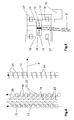
- FIG. 7 shows a top view of the target elements and the deflection devices 21 of a further computer tomograph 1 according to the invention for medical applications.
- the representation corresponds to the plan view (left representation) of Figure 3.
- a further target 14 'is provided which likewise consists of a multiplicity of individual target elements with discrete focus areas 20.
- the individual target elements of a target are in each case arranged at a distance a from each other on a circular path.
- the further target 14 ' is arranged such that the individual target elements are each offset by a quarter period spacing a / 4 with respect to the first target elements.
- Such an embodiment is advantageous if the focus of the electron beam 13, which is indicated here by a dot-dash line, two lines of the detector 6, not shown here are assigned. If the data of the focus are written in two lines, twice the number of independent projections already results.
- a further target 14 ' is arranged offset by a quarter period, wherein the second target 14' is assigned a second detector row, then the full circle can be completely filled up with radiation sources, as will be explained in more detail below.
- the individual target elements are arranged here in the same way as in the representation of FIG. 3 with respect to the circulating electron beam 13 such that a deflection angle ⁇ of 32 ° results.
- the individual target elements have a lead angle ⁇ of 6 ° here.
- an odd number of target elements distributed on the circumference of the full circle so that the gaps I between the individual target elements each by a beam from the opposite side of the target ring to be hit.
- additional independent projections are obtained by the rays of the opposite side of the ring.
- a further target 14 ' is arranged offset, then the two target elements are successively scanned by the respectively correspondingly deflected electron beam 13'.
- the gap L which thereby initially results on the circumference of the full circle, and from which initially no information is obtained, is finally filled during one revolution of the electron beam by the radiation of the target elements of the opposite side.
- an additional target 14 ' can be reduced by the arrangement of an additional target 14 ', the instantaneous heat load.
- the arrangement of an additional target 14 ' which is arranged offset by a quarter period to the first, moreover makes it possible to reduce the number of individual target elements on the target 14, 14'.
- the distance a between periodically successive target elements is thereby somewhat larger, so that more space is available for the deflection elements 21 and for the electron optics.
- This also makes it possible to arrange an additional ring with pinhole diaphragms, which also collimates the generated X-ray beam in the plane of the ring.
- FIG. 8 shows a schematic representation of a computer tomograph 1 according to the invention for technical applications in a view of the annular structure of the computer tomograph 1.
- the illustration shows the ring structure of the computer tomograph 1, wherein the individual target elements are designed as transmission targets 35.
- kinetic energies in the range of 1 to 3 megaelectronvolts are desired. These can be generated by means of a corresponding accelerator, which is designed as a linear accelerator or Microtronbeschreiber, in an external electron gun and, for example, as described, are fed tangentially into the beam guide tube.
- the irradiation targets 35 are arranged such that the generated x-radiation 8 is emitted in the direction of the isocenter 9 of the computed tomograph 1.
- the electron beam 13 in this case does not run parallel to the target ring, but on a circular path with a larger radius than the target ring.
- the deflection devices 21 are in this case designed such that the electron beam 13 is deflected in each case in front of the target by 90 °, so that the electrons as possible radially in the direction of the center. In contrast to the previously described embodiments only a point focus is generated here.
- each balancing body 36 are mounted, which consist for example of stainless steel. These keep the intensity of the X-radiation above the field of view approximately homogeneous.
- the balancing bodies 36 are mounted on a ring (not shown here) close behind the transmission targets 35, wherein the ring has a kind of sawtooth structure.
- a plurality of transmission targets 35 for example three targets
- the electron beam 13 ' is in this case also directed alternately from the pure 90 ° deflection to the other targets.
- the number of deflection devices 21 or kick devices can be reduced, so that more space is available for the design of the deflection and focusing.
- the detectors 6 For the operation with such high energies, the detectors 6 must be adapted accordingly, with preferably solid-state detectors being used.
- the other components are not shown here and essentially correspond to those already described for medical applications with lower energies.
- improved shielding against stray radiation is required, for which purpose a scattered radiation grid 29, as described in FIG. 2, can be arranged, which preferably consists of rigid metal rings, for example of tungsten.
- the shielding of the entire structure against the forward radiation is to be designed accordingly.
- the diaphragms are to be adapted to the higher penetration of the hard radiation, so that tungsten diaphragms are preferably used.
- the computer tomograph 1 can also be adapted in its dimensions to the examination of very large objects.
- the diameter of the annular target 14 can also be in the order of magnitude of up to 8 m, with, for example, 601 individual target elements being arranged on the circumference.
- a specific number of individual target elements is then arranged in each case on a straight subsegment.
- the individual sub-segments are finally connected to each other in a vacuum-tight manner.
- FIG. 9 shows a schematic representation of the arrangement of transmission targets 35 of a computer tomograph 1 for technical applications.
- the individual target elements are designed as transmission targets 35 for technical applications with high electron energies.
- the electron beam 13 in this case runs as described on a circular path with a larger radius than that of the fürstrahlungstargets 35 and is deflected from there in each case by 90 ° in the direction of the isocenter 9 of the device. In the present representation, this is indicated by the points on the radiation target 35.
- a dense scan i. Projections from as far as possible every angular range of the full circle. Since in the beam direction behind the fürstrahlungstargets 35 each still a compensating body 36 is to be arranged, which is necessarily on a smaller radius, it may come with tight arrangement of the fürstrahlungstargets 35 space problems of the balancing body 36. In the present case, therefore, the individual irradiation targets 35 are arranged inclined at 45 ° to the electron beam 13.
- the compensating bodies 36 which are not visible in the present illustration, are hereby designed in the form of a triangle and are likewise arranged at an angle of 45 ° with respect to the rotating electron beam 13. Due to the formation in the form of a triangle, the compensation bodies 36 can be placed despite a dense arrangement of irradiation targets 35. As a compensating body is effective here is a section of the triangle with a cutting angle of 45 °.
- the arrangement of the compensating bodies 36 with respect to the irradiation targets 35 is shown schematically in FIG. 10, wherein a view in the direction of the arrow P of FIG. 9 is shown.
- the transmission target 35 can be scanned across at 45 ° as indicated by line 35.
- additional scanning magnets (not shown here) are arranged between the rotating electron beam 13 and the radiation target 35 in this embodiment. The resolution of the generated image can thereby be improved.
- the focus can also be designed as a spring focus, the data being written in two or more detector rows.
- the tracks of the spring focus are indicated by the lines 39.
Applications Claiming Priority (3)
| Application Number | Priority Date | Filing Date | Title |
|---|---|---|---|
| DE102006035742 | 2006-07-28 | ||
| DE102006049630 | 2006-10-20 | ||
| DE102007019176A DE102007019176A1 (de) | 2006-07-28 | 2007-04-20 | Computertomograph |
Publications (3)
| Publication Number | Publication Date |
|---|---|
| EP1883093A2 true EP1883093A2 (fr) | 2008-01-30 |
| EP1883093A3 EP1883093A3 (fr) | 2010-02-24 |
| EP1883093B1 EP1883093B1 (fr) | 2011-11-16 |
Family
ID=38683544
Family Applications (1)
| Application Number | Title | Priority Date | Filing Date |
|---|---|---|---|
| EP07111789A Not-in-force EP1883093B1 (fr) | 2006-07-28 | 2007-07-05 | Tomodensitomètre |
Country Status (2)
| Country | Link |
|---|---|
| US (1) | US7580500B2 (fr) |
| EP (1) | EP1883093B1 (fr) |
Cited By (3)
| Publication number | Priority date | Publication date | Assignee | Title |
|---|---|---|---|---|
| EP2092545B1 (fr) * | 2006-11-10 | 2012-08-29 | Philips Intellectual Property & Standards GmbH | Tube à rayons x à multiples points focaux avec de multiples unités de manipulation du faisceau électronique |
| WO2014166468A1 (fr) * | 2013-04-09 | 2014-10-16 | Helmholtz-Zentrum Dresden-Rossendorf E.V. | Dispositif de tomodensitométrie rapide par faisceau d'électrons |
| CN111166363A (zh) * | 2014-05-01 | 2020-05-19 | 斯格瑞公司 | X射线干涉成像系统 |
Families Citing this family (14)
| Publication number | Priority date | Publication date | Assignee | Title |
|---|---|---|---|---|
| US7963695B2 (en) | 2002-07-23 | 2011-06-21 | Rapiscan Systems, Inc. | Rotatable boom cargo scanning system |
| US7899156B2 (en) * | 2008-07-16 | 2011-03-01 | L-3 Communications Security And Detection Systems, Inc. | Irradiation system including an electron-beam scanner |
| US8053745B2 (en) * | 2009-02-24 | 2011-11-08 | Moore John F | Device and method for administering particle beam therapy |
| DE102009002114B4 (de) * | 2009-04-01 | 2012-03-15 | Helmholtz-Zentrum Dresden - Rossendorf E.V. | Anordnung zur Elektronenstrahltomographie |
| US9442213B2 (en) | 2010-01-19 | 2016-09-13 | Rapiscan Systems, Inc. | Method of electron beam transport in an X-ray scanner |
| CN102804326B (zh) * | 2010-01-19 | 2016-01-20 | 拉皮斯坎系统股份有限公司 | 多视图货物扫描器 |
| US8714818B2 (en) * | 2011-05-20 | 2014-05-06 | Consensys Imaging Service, Inc. | Real-time x-ray monitoring |
| DE102011108508A1 (de) | 2011-07-25 | 2013-01-31 | Carl Zeiss Meditec Ag | Anpassung eines Strahlungsfelds |
| DE102012005767A1 (de) * | 2012-03-25 | 2013-09-26 | DüRR DENTAL AG | Phasenkontrast-Röntgen-Tomographiegerät |
| US9490099B2 (en) | 2014-08-20 | 2016-11-08 | Wisconsin Alumni Research Foundation | System and method for multi-source X-ray-based imaging |
| US10390774B2 (en) * | 2014-11-19 | 2019-08-27 | Guy M. Besson | Annular ring target multi-source CT system |
| MX2017009342A (es) | 2015-01-20 | 2017-11-17 | American Science & Eng Inc | Punto focal dinamicamente ajustable. |
| WO2018144630A1 (fr) | 2017-01-31 | 2018-08-09 | Rapiscan Systems, Inc. | Sources de rayons x haute puissance et procédés de fonctionnement |
| EP3933881A1 (fr) | 2020-06-30 | 2022-01-05 | VEC Imaging GmbH & Co. KG | Source de rayons x à plusieurs réseaux |
Citations (3)
| Publication number | Priority date | Publication date | Assignee | Title |
|---|---|---|---|---|
| US4531226A (en) | 1983-03-17 | 1985-07-23 | Imatron Associates | Multiple electron beam target for use in X-ray scanner |
| DE4210339A1 (de) | 1991-05-03 | 1992-12-10 | Bruker Analytische Messtechnik | Elektronenstrahl-roentgen-computer-tomographie-geraet |
| US5490193A (en) | 1990-07-23 | 1996-02-06 | Hitachi, Ltd. | X-ray computed tomography system |
Family Cites Families (17)
| Publication number | Priority date | Publication date | Assignee | Title |
|---|---|---|---|---|
| US4130759A (en) | 1977-03-17 | 1978-12-19 | Haimson Research Corporation | Method and apparatus incorporating no moving parts, for producing and selectively directing x-rays to different points on an object |
| GB2044985A (en) * | 1979-03-15 | 1980-10-22 | Emi Ltd | X-ray tube |
| US4631741A (en) * | 1984-04-05 | 1986-12-23 | Imatron, Inc. | Beam spot monitoring arrangement for use in a scanning electron beam computed tomography scanner and method |
| EP0455177A3 (en) * | 1990-04-30 | 1992-05-20 | Shimadzu Corporation | High-speed scan type x-ray generator |
| DE4103588C1 (fr) * | 1991-02-06 | 1992-05-27 | Siemens Ag, 8000 Muenchen, De | |
| DE4409365C1 (de) * | 1994-03-18 | 1995-03-16 | Siemens Ag | Röntgencomputertomograph |
| DE4433133C1 (de) * | 1994-09-16 | 1995-12-07 | Siemens Ag | Röntgenstrahler mit einer Elektronenquelle zum Senden eines Bündels von Elektronen entlang einer langgestreckten Anode |
| DE19515415A1 (de) * | 1995-04-26 | 1996-11-07 | Siemens Ag | Röntgenstrahlerzeuger |
| DE19621066A1 (de) | 1996-05-24 | 1997-11-27 | Siemens Ag | Röntgenstrahler mit einem Führungs- und einem Kickmagnetsystem für Elektronen |
| DE19710222A1 (de) * | 1997-03-12 | 1998-09-17 | Siemens Ag | Röntgenstrahlerzeuger |
| US7068749B2 (en) * | 2003-05-19 | 2006-06-27 | General Electric Company | Stationary computed tomography system with compact x ray source assembly |
| US6968042B2 (en) * | 2003-09-12 | 2005-11-22 | Ge Medical Systems Global Technology Company, Llc | Methods and apparatus for target angle heel effect compensation |
| US7280631B2 (en) * | 2003-11-26 | 2007-10-09 | General Electric Company | Stationary computed tomography system and method |
| US7218700B2 (en) | 2004-05-28 | 2007-05-15 | General Electric Company | System for forming x-rays and method for using same |
| US7233644B1 (en) * | 2004-11-30 | 2007-06-19 | Ge Homeland Protection, Inc. | Computed tomographic scanner using rastered x-ray tubes |
| US7616731B2 (en) * | 2006-08-30 | 2009-11-10 | General Electric Company | Acquisition and reconstruction of projection data using a stationary CT geometry |
| US7706499B2 (en) * | 2006-08-30 | 2010-04-27 | General Electric Company | Acquisition and reconstruction of projection data using a stationary CT geometry |
-
2007
- 2007-07-05 EP EP07111789A patent/EP1883093B1/fr not_active Not-in-force
- 2007-07-27 US US11/829,222 patent/US7580500B2/en not_active Expired - Fee Related
Patent Citations (3)
| Publication number | Priority date | Publication date | Assignee | Title |
|---|---|---|---|---|
| US4531226A (en) | 1983-03-17 | 1985-07-23 | Imatron Associates | Multiple electron beam target for use in X-ray scanner |
| US5490193A (en) | 1990-07-23 | 1996-02-06 | Hitachi, Ltd. | X-ray computed tomography system |
| DE4210339A1 (de) | 1991-05-03 | 1992-12-10 | Bruker Analytische Messtechnik | Elektronenstrahl-roentgen-computer-tomographie-geraet |
Cited By (4)
| Publication number | Priority date | Publication date | Assignee | Title |
|---|---|---|---|---|
| EP2092545B1 (fr) * | 2006-11-10 | 2012-08-29 | Philips Intellectual Property & Standards GmbH | Tube à rayons x à multiples points focaux avec de multiples unités de manipulation du faisceau électronique |
| WO2014166468A1 (fr) * | 2013-04-09 | 2014-10-16 | Helmholtz-Zentrum Dresden-Rossendorf E.V. | Dispositif de tomodensitométrie rapide par faisceau d'électrons |
| CN111166363A (zh) * | 2014-05-01 | 2020-05-19 | 斯格瑞公司 | X射线干涉成像系统 |
| CN111166363B (zh) * | 2014-05-01 | 2023-12-12 | 斯格瑞公司 | X射线干涉成像系统 |
Also Published As
| Publication number | Publication date |
|---|---|
| EP1883093A3 (fr) | 2010-02-24 |
| US7580500B2 (en) | 2009-08-25 |
| US20080137805A1 (en) | 2008-06-12 |
| EP1883093B1 (fr) | 2011-11-16 |
Similar Documents
| Publication | Publication Date | Title |
|---|---|---|
| EP1883093B1 (fr) | Tomodensitomètre | |
| DE2902308C2 (de) | Röntgenröhre | |
| DE102008033150B4 (de) | Röntgenquelle sowie Mammographieanlage und Röntgenanlage mit einer solchen Röntgenquelle | |
| DE102006062667B4 (de) | Vorrichtung für die Ausgabe von Hoch- und/oder Niederenergieröntgenstrahlen | |
| DE102014202330B3 (de) | Single Source DualEnergy mit zwei Filtern zur Röntgenspektrumsdifferenzierung bei Strahlerblenden mit Schlitzplatte | |
| DE4434704C1 (de) | Röntgenröhre mit einem ringförmigen Vakuumgehäuse | |
| DE4015180C2 (fr) | ||
| DE4015105C3 (de) | Röntgen-Computer-Tomographie-System | |
| DE2559658A1 (de) | Radiographisches geraet | |
| EP1642618A1 (fr) | Dispositif de radiothérapie | |
| DE102007035177A1 (de) | Computertomographie-System mit feststehendem Anodenring | |
| EP2252216B1 (fr) | Agencement pour tomographie à faisceau d'électrons en trois dimensions | |
| DE102009039345A1 (de) | Vorrichtung zur Bestrahlungsfeldkontrolle bei radiologischen Strahlentherapiegeräten | |
| WO2004029991A1 (fr) | Dispositif obturateur et appareil de tomographie informatique comportant un dispositif obturateur cote faisceau | |
| DE102004061347B3 (de) | Röntgen-Computertomograph für schnelle Bildaufzeichung | |
| DE102009035439A1 (de) | Röntgen-CT-System zur tomographischen Darstellung eines Untersuchungsobjektes, aufweisend eine Röntgenröhre zur Erzeugung von Röntgenstrahlung | |
| DE2723462A1 (de) | Roentgendiagnostikgeraet fuer transversalschichtbilder | |
| DE102006006840A1 (de) | Röntgen-Computertomograph mit Lichtstrahl-gesteuerter Röntgenquelle | |
| DE10356601B4 (de) | Vorrichtung zur Röntgentomographie mit einem elektromagnetisch abgelenkten Elektronenstrahl | |
| WO2014075700A1 (fr) | Source de rayons x, collimateur, poste de travail radiologique et procédé permettant leur fonctionnement | |
| DE102006029198A1 (de) | Computertomographie-System und Verfahren zur Erzeugung von Schnittbildaufnahmen | |
| DE102007019176A1 (de) | Computertomograph | |
| DE102012203807A1 (de) | Röntgenröhre | |
| DE102016101787B4 (de) | Tomographievorrichtung | |
| EP2117435A1 (fr) | Installation de tomodensitométrie à rayons x |
Legal Events
| Date | Code | Title | Description |
|---|---|---|---|
| PUAI | Public reference made under article 153(3) epc to a published international application that has entered the european phase |
Free format text: ORIGINAL CODE: 0009012 |
|
| AK | Designated contracting states |
Kind code of ref document: A2 Designated state(s): AT BE BG CH CY CZ DE DK EE ES FI FR GB GR HU IE IS IT LI LT LU LV MC MT NL PL PT RO SE SI SK TR |
|
| AX | Request for extension of the european patent |
Extension state: AL BA HR MK YU |
|
| PUAL | Search report despatched |
Free format text: ORIGINAL CODE: 0009013 |
|
| AK | Designated contracting states |
Kind code of ref document: A3 Designated state(s): AT BE BG CH CY CZ DE DK EE ES FI FR GB GR HU IE IS IT LI LT LU LV MC MT NL PL PT RO SE SI SK TR |
|
| AX | Request for extension of the european patent |
Extension state: AL BA HR MK RS |
|
| 17P | Request for examination filed |
Effective date: 20100824 |
|
| 17Q | First examination report despatched |
Effective date: 20100921 |
|
| AKX | Designation fees paid |
Designated state(s): AT BE BG CH CY CZ DE DK EE ES FI FR GB GR HU IE IS IT LI LT LU LV MC MT NL PL PT RO SE SI SK TR |
|
| GRAP | Despatch of communication of intention to grant a patent |
Free format text: ORIGINAL CODE: EPIDOSNIGR1 |
|
| GRAS | Grant fee paid |
Free format text: ORIGINAL CODE: EPIDOSNIGR3 |
|
| GRAA | (expected) grant |
Free format text: ORIGINAL CODE: 0009210 |
|
| AK | Designated contracting states |
Kind code of ref document: B1 Designated state(s): AT BE BG CH CY CZ DE DK EE ES FI FR GB GR HU IE IS IT LI LT LU LV MC MT NL PL PT RO SE SI SK TR |
|
| REG | Reference to a national code |
Ref country code: GB Ref legal event code: FG4D Free format text: NOT ENGLISH |
|
| REG | Reference to a national code |
Ref country code: CH Ref legal event code: EP |
|
| REG | Reference to a national code |
Ref country code: IE Ref legal event code: FG4D Free format text: LANGUAGE OF EP DOCUMENT: GERMAN |
|
| REG | Reference to a national code |
Ref country code: DE Ref legal event code: R096 Ref document number: 502007008676 Country of ref document: DE Effective date: 20120119 |
|
| REG | Reference to a national code |
Ref country code: NL Ref legal event code: VDEP Effective date: 20111116 |
|
| LTIE | Lt: invalidation of european patent or patent extension |
Effective date: 20111116 |
|
| PG25 | Lapsed in a contracting state [announced via postgrant information from national office to epo] |
Ref country code: LT Free format text: LAPSE BECAUSE OF FAILURE TO SUBMIT A TRANSLATION OF THE DESCRIPTION OR TO PAY THE FEE WITHIN THE PRESCRIBED TIME-LIMIT Effective date: 20111116 Ref country code: IS Free format text: LAPSE BECAUSE OF FAILURE TO SUBMIT A TRANSLATION OF THE DESCRIPTION OR TO PAY THE FEE WITHIN THE PRESCRIBED TIME-LIMIT Effective date: 20120316 |
|
| PG25 | Lapsed in a contracting state [announced via postgrant information from national office to epo] |
Ref country code: SE Free format text: LAPSE BECAUSE OF FAILURE TO SUBMIT A TRANSLATION OF THE DESCRIPTION OR TO PAY THE FEE WITHIN THE PRESCRIBED TIME-LIMIT Effective date: 20111116 Ref country code: SI Free format text: LAPSE BECAUSE OF FAILURE TO SUBMIT A TRANSLATION OF THE DESCRIPTION OR TO PAY THE FEE WITHIN THE PRESCRIBED TIME-LIMIT Effective date: 20111116 Ref country code: PL Free format text: LAPSE BECAUSE OF FAILURE TO SUBMIT A TRANSLATION OF THE DESCRIPTION OR TO PAY THE FEE WITHIN THE PRESCRIBED TIME-LIMIT Effective date: 20111116 Ref country code: GR Free format text: LAPSE BECAUSE OF FAILURE TO SUBMIT A TRANSLATION OF THE DESCRIPTION OR TO PAY THE FEE WITHIN THE PRESCRIBED TIME-LIMIT Effective date: 20120217 Ref country code: LV Free format text: LAPSE BECAUSE OF FAILURE TO SUBMIT A TRANSLATION OF THE DESCRIPTION OR TO PAY THE FEE WITHIN THE PRESCRIBED TIME-LIMIT Effective date: 20111116 Ref country code: NL Free format text: LAPSE BECAUSE OF FAILURE TO SUBMIT A TRANSLATION OF THE DESCRIPTION OR TO PAY THE FEE WITHIN THE PRESCRIBED TIME-LIMIT Effective date: 20111116 Ref country code: PT Free format text: LAPSE BECAUSE OF FAILURE TO SUBMIT A TRANSLATION OF THE DESCRIPTION OR TO PAY THE FEE WITHIN THE PRESCRIBED TIME-LIMIT Effective date: 20120316 |
|
| REG | Reference to a national code |
Ref country code: IE Ref legal event code: FD4D |
|
| PG25 | Lapsed in a contracting state [announced via postgrant information from national office to epo] |
Ref country code: CY Free format text: LAPSE BECAUSE OF FAILURE TO SUBMIT A TRANSLATION OF THE DESCRIPTION OR TO PAY THE FEE WITHIN THE PRESCRIBED TIME-LIMIT Effective date: 20111116 |
|
| PG25 | Lapsed in a contracting state [announced via postgrant information from national office to epo] |
Ref country code: BG Free format text: LAPSE BECAUSE OF FAILURE TO SUBMIT A TRANSLATION OF THE DESCRIPTION OR TO PAY THE FEE WITHIN THE PRESCRIBED TIME-LIMIT Effective date: 20120216 Ref country code: EE Free format text: LAPSE BECAUSE OF FAILURE TO SUBMIT A TRANSLATION OF THE DESCRIPTION OR TO PAY THE FEE WITHIN THE PRESCRIBED TIME-LIMIT Effective date: 20111116 Ref country code: IE Free format text: LAPSE BECAUSE OF FAILURE TO SUBMIT A TRANSLATION OF THE DESCRIPTION OR TO PAY THE FEE WITHIN THE PRESCRIBED TIME-LIMIT Effective date: 20111116 Ref country code: DK Free format text: LAPSE BECAUSE OF FAILURE TO SUBMIT A TRANSLATION OF THE DESCRIPTION OR TO PAY THE FEE WITHIN THE PRESCRIBED TIME-LIMIT Effective date: 20111116 Ref country code: CZ Free format text: LAPSE BECAUSE OF FAILURE TO SUBMIT A TRANSLATION OF THE DESCRIPTION OR TO PAY THE FEE WITHIN THE PRESCRIBED TIME-LIMIT Effective date: 20111116 Ref country code: SK Free format text: LAPSE BECAUSE OF FAILURE TO SUBMIT A TRANSLATION OF THE DESCRIPTION OR TO PAY THE FEE WITHIN THE PRESCRIBED TIME-LIMIT Effective date: 20111116 |
|
| PG25 | Lapsed in a contracting state [announced via postgrant information from national office to epo] |
Ref country code: IT Free format text: LAPSE BECAUSE OF FAILURE TO SUBMIT A TRANSLATION OF THE DESCRIPTION OR TO PAY THE FEE WITHIN THE PRESCRIBED TIME-LIMIT Effective date: 20111116 Ref country code: RO Free format text: LAPSE BECAUSE OF FAILURE TO SUBMIT A TRANSLATION OF THE DESCRIPTION OR TO PAY THE FEE WITHIN THE PRESCRIBED TIME-LIMIT Effective date: 20111116 |
|
| REG | Reference to a national code |
Ref country code: DE Ref legal event code: R082 Ref document number: 502007008676 Country of ref document: DE Representative=s name: GROSSE, SCHUMACHER, KNAUER VON HIRSCHHAUSEN, DE Ref country code: DE Ref legal event code: R082 Ref document number: 502007008676 Country of ref document: DE Representative=s name: GROSSE, SCHUMACHER, KNAUER, VON HIRSCHHAUSEN, DE |
|
| PLBE | No opposition filed within time limit |
Free format text: ORIGINAL CODE: 0009261 |
|
| STAA | Information on the status of an ep patent application or granted ep patent |
Free format text: STATUS: NO OPPOSITION FILED WITHIN TIME LIMIT |
|
| 26N | No opposition filed |
Effective date: 20120817 |
|
| REG | Reference to a national code |
Ref country code: DE Ref legal event code: R097 Ref document number: 502007008676 Country of ref document: DE Effective date: 20120817 |
|
| PGFP | Annual fee paid to national office [announced via postgrant information from national office to epo] |
Ref country code: DE Payment date: 20120731 Year of fee payment: 6 |
|
| BERE | Be: lapsed |
Owner name: FORSTER, JAN Effective date: 20120731 Owner name: FORSTER, RENATE Effective date: 20120731 |
|
| PG25 | Lapsed in a contracting state [announced via postgrant information from national office to epo] |
Ref country code: MC Free format text: LAPSE BECAUSE OF NON-PAYMENT OF DUE FEES Effective date: 20120731 |
|
| REG | Reference to a national code |
Ref country code: CH Ref legal event code: PL |
|
| GBPC | Gb: european patent ceased through non-payment of renewal fee |
Effective date: 20120705 |
|
| REG | Reference to a national code |
Ref country code: FR Ref legal event code: ST Effective date: 20130329 |
|
| PG25 | Lapsed in a contracting state [announced via postgrant information from national office to epo] |
Ref country code: ES Free format text: LAPSE BECAUSE OF FAILURE TO SUBMIT A TRANSLATION OF THE DESCRIPTION OR TO PAY THE FEE WITHIN THE PRESCRIBED TIME-LIMIT Effective date: 20120227 Ref country code: GB Free format text: LAPSE BECAUSE OF NON-PAYMENT OF DUE FEES Effective date: 20120705 Ref country code: FR Free format text: LAPSE BECAUSE OF NON-PAYMENT OF DUE FEES Effective date: 20120731 Ref country code: LI Free format text: LAPSE BECAUSE OF NON-PAYMENT OF DUE FEES Effective date: 20120731 Ref country code: CH Free format text: LAPSE BECAUSE OF NON-PAYMENT OF DUE FEES Effective date: 20120731 |
|
| PG25 | Lapsed in a contracting state [announced via postgrant information from national office to epo] |
Ref country code: BE Free format text: LAPSE BECAUSE OF NON-PAYMENT OF DUE FEES Effective date: 20120731 |
|
| PG25 | Lapsed in a contracting state [announced via postgrant information from national office to epo] |
Ref country code: FI Free format text: LAPSE BECAUSE OF FAILURE TO SUBMIT A TRANSLATION OF THE DESCRIPTION OR TO PAY THE FEE WITHIN THE PRESCRIBED TIME-LIMIT Effective date: 20111116 |
|
| PG25 | Lapsed in a contracting state [announced via postgrant information from national office to epo] |
Ref country code: MT Free format text: LAPSE BECAUSE OF FAILURE TO SUBMIT A TRANSLATION OF THE DESCRIPTION OR TO PAY THE FEE WITHIN THE PRESCRIBED TIME-LIMIT Effective date: 20111116 |
|
| REG | Reference to a national code |
Ref country code: AT Ref legal event code: MM01 Ref document number: 534135 Country of ref document: AT Kind code of ref document: T Effective date: 20120731 |
|
| PG25 | Lapsed in a contracting state [announced via postgrant information from national office to epo] |
Ref country code: AT Free format text: LAPSE BECAUSE OF NON-PAYMENT OF DUE FEES Effective date: 20120731 |
|
| REG | Reference to a national code |
Ref country code: DE Ref legal event code: R119 Ref document number: 502007008676 Country of ref document: DE Effective date: 20140201 |
|
| PG25 | Lapsed in a contracting state [announced via postgrant information from national office to epo] |
Ref country code: TR Free format text: LAPSE BECAUSE OF FAILURE TO SUBMIT A TRANSLATION OF THE DESCRIPTION OR TO PAY THE FEE WITHIN THE PRESCRIBED TIME-LIMIT Effective date: 20111116 Ref country code: DE Free format text: LAPSE BECAUSE OF NON-PAYMENT OF DUE FEES Effective date: 20140201 |
|
| PG25 | Lapsed in a contracting state [announced via postgrant information from national office to epo] |
Ref country code: LU Free format text: LAPSE BECAUSE OF NON-PAYMENT OF DUE FEES Effective date: 20120705 |
|
| PG25 | Lapsed in a contracting state [announced via postgrant information from national office to epo] |
Ref country code: HU Free format text: LAPSE BECAUSE OF FAILURE TO SUBMIT A TRANSLATION OF THE DESCRIPTION OR TO PAY THE FEE WITHIN THE PRESCRIBED TIME-LIMIT Effective date: 20070705 |