EP1882284B1 - Battery pack management method for hev and ev - Google Patents
Battery pack management method for hev and ev Download PDFInfo
- Publication number
- EP1882284B1 EP1882284B1 EP06747374A EP06747374A EP1882284B1 EP 1882284 B1 EP1882284 B1 EP 1882284B1 EP 06747374 A EP06747374 A EP 06747374A EP 06747374 A EP06747374 A EP 06747374A EP 1882284 B1 EP1882284 B1 EP 1882284B1
- Authority
- EP
- European Patent Office
- Prior art keywords
- battery pack
- charge relay
- relay
- connection circuit
- bms
- Prior art date
- Legal status (The legal status is an assumption and is not a legal conclusion. Google has not performed a legal analysis and makes no representation as to the accuracy of the status listed.)
- Expired - Lifetime
Links
Images
Classifications
-
- A—HUMAN NECESSITIES
- A47—FURNITURE; DOMESTIC ARTICLES OR APPLIANCES; COFFEE MILLS; SPICE MILLS; SUCTION CLEANERS IN GENERAL
- A47K—SANITARY EQUIPMENT; ACCESSORIES THEREFOR, e.g. TOILET ACCESSORIES
- A47K13/00—Seats or covers for all kinds of closets
- A47K13/10—Devices for raising and lowering ; Collapsible or rotating seats or covers
-
- H—ELECTRICITY
- H01—ELECTRIC ELEMENTS
- H01M—PROCESSES OR MEANS, e.g. BATTERIES, FOR THE DIRECT CONVERSION OF CHEMICAL ENERGY INTO ELECTRICAL ENERGY
- H01M10/00—Secondary cells; Manufacture thereof
- H01M10/42—Methods or arrangements for servicing or maintenance of secondary cells or secondary half-cells
- H01M10/44—Methods for charging or discharging
- H01M10/441—Methods for charging or discharging for several batteries or cells simultaneously or sequentially
-
- H—ELECTRICITY
- H01—ELECTRIC ELEMENTS
- H01M—PROCESSES OR MEANS, e.g. BATTERIES, FOR THE DIRECT CONVERSION OF CHEMICAL ENERGY INTO ELECTRICAL ENERGY
- H01M10/00—Secondary cells; Manufacture thereof
- H01M10/42—Methods or arrangements for servicing or maintenance of secondary cells or secondary half-cells
- H01M10/48—Accumulators combined with arrangements for measuring, testing or indicating the condition of cells, e.g. the level or density of the electrolyte
- H01M10/482—Accumulators combined with arrangements for measuring, testing or indicating the condition of cells, e.g. the level or density of the electrolyte for several batteries or cells simultaneously or sequentially
-
- H—ELECTRICITY
- H02—GENERATION; CONVERSION OR DISTRIBUTION OF ELECTRIC POWER
- H02J—ELECTRIC POWER NETWORKS; CIRCUIT ARRANGEMENTS OR SYSTEMS FOR SUPPLYING OR DISTRIBUTING ELECTRIC POWER; SYSTEMS FOR STORING ELECTRIC ENERGY
- H02J7/00—Circuit arrangements for charging or discharging batteries or for supplying loads from batteries
- H02J7/60—Circuit arrangements for charging or discharging batteries or for supplying loads from batteries including safety or protection arrangements
- H02J7/61—Circuit arrangements for charging or discharging batteries or for supplying loads from batteries including safety or protection arrangements against overcharge
-
- H—ELECTRICITY
- H02—GENERATION; CONVERSION OR DISTRIBUTION OF ELECTRIC POWER
- H02J—ELECTRIC POWER NETWORKS; CIRCUIT ARRANGEMENTS OR SYSTEMS FOR SUPPLYING OR DISTRIBUTING ELECTRIC POWER; SYSTEMS FOR STORING ELECTRIC ENERGY
- H02J7/00—Circuit arrangements for charging or discharging batteries or for supplying loads from batteries
- H02J7/60—Circuit arrangements for charging or discharging batteries or for supplying loads from batteries including safety or protection arrangements
- H02J7/64—Circuit arrangements for charging or discharging batteries or for supplying loads from batteries including safety or protection arrangements against overvoltage
-
- H—ELECTRICITY
- H02—GENERATION; CONVERSION OR DISTRIBUTION OF ELECTRIC POWER
- H02J—ELECTRIC POWER NETWORKS; CIRCUIT ARRANGEMENTS OR SYSTEMS FOR SUPPLYING OR DISTRIBUTING ELECTRIC POWER; SYSTEMS FOR STORING ELECTRIC ENERGY
- H02J7/00—Circuit arrangements for charging or discharging batteries or for supplying loads from batteries
- H02J7/60—Circuit arrangements for charging or discharging batteries or for supplying loads from batteries including safety or protection arrangements
- H02J7/663—Circuit arrangements for charging or discharging batteries or for supplying loads from batteries including safety or protection arrangements using battery or load disconnect circuits
-
- H—ELECTRICITY
- H01—ELECTRIC ELEMENTS
- H01M—PROCESSES OR MEANS, e.g. BATTERIES, FOR THE DIRECT CONVERSION OF CHEMICAL ENERGY INTO ELECTRICAL ENERGY
- H01M10/00—Secondary cells; Manufacture thereof
- H01M10/42—Methods or arrangements for servicing or maintenance of secondary cells or secondary half-cells
- H01M10/44—Methods for charging or discharging
- H01M10/448—End of discharge regulating measures
-
- Y—GENERAL TAGGING OF NEW TECHNOLOGICAL DEVELOPMENTS; GENERAL TAGGING OF CROSS-SECTIONAL TECHNOLOGIES SPANNING OVER SEVERAL SECTIONS OF THE IPC; TECHNICAL SUBJECTS COVERED BY FORMER USPC CROSS-REFERENCE ART COLLECTIONS [XRACs] AND DIGESTS
- Y02—TECHNOLOGIES OR APPLICATIONS FOR MITIGATION OR ADAPTATION AGAINST CLIMATE CHANGE
- Y02E—REDUCTION OF GREENHOUSE GAS [GHG] EMISSIONS, RELATED TO ENERGY GENERATION, TRANSMISSION OR DISTRIBUTION
- Y02E60/00—Enabling technologies; Technologies with a potential or indirect contribution to GHG emissions mitigation
- Y02E60/10—Energy storage using batteries
Definitions
- the invention relates to a battery pack management method for HEV and EV, and more particularly to a battery pack management method for HEV and EV capable of properly controlling a battery pack connection circuit provided between a battery pack and a power conversion circuit through a battery management system (BMS) of the battery pack or a vehicle control device so that a smoothing capacitor or related devices of the power conversion circuit can be prevented from being damaged in advance when surge current is applied to the power conversion circuit of a vehicle motor unit from the battery pack in starting the vehicle with a start key, and notifying a driver of a diagnosis result through warning means when over-current flows to a pre-charge resistor of the battery pack connection circuit or a pre-charge relay of the battery pack connection circuit is turned off due to over-current or over-voltage during the driving, thereby contributing to a safety drive of the vehicle.
- BMS battery management system
- the HEV is driven with a driving motor, which uses electricity supplied from a main battery via a power conversion circuit as a driving source, as well as an internal combustion engine using the gasoline, diesel oil or LPG as the fuel. Further, the HEV is controlled so that the fuel efficiency of the vehicle is improved to the utmost in correspondence with each driving situation.
- the driving motor of the HEV is converted into a generation mode from a driving mode though control of a hybrid control unit (HCU) when the vehicle is braked or decelerated.
- HCU hybrid control unit
- the main battery is charged case-by-case by the electric energy generated from a generator (or driving motor) under control of a battery management system (BMS) connected to the HCU.
- BMS battery management system
- the currents applied to the main battery from the generator are different and discontinuous depending on the driving situations of the vehicle.
- a battery pack connection circuit 1 is provided between the power conversion circuit and the main battery for the driving motor.
- the battery pack connection circuit 1 applies a charge current to the main battery from the driving motor (or generator) under generation mode and applies a driving current to the driving motor from the main battery under driving mode, so that the vehicle is driven by the electric energy.
- HV (-) lead and a HV (+) lead for applying the current to the power conversion circuit from the main battery, in a predetermined pattern.
- a pre-charge resistor 2 for limiting a surge over-current applied to the power conversion circuit from the main battery when the vehicle is started.
- a pre-charge relay 3 for high-voltage and a relay 4 for high-voltage main power supply capable of controlling the over-current are respectively connected between the pre-charge resistor and an output terminal through different routes.
- the HV (-) lead is provided with a separate relay 4a for main power supply capable of controlling the over-current applied to the driving motor from the main battery.
- the relays 4, 4a and the pre-charge relay 3 are respectively provided with condensers connected through a control lead applied with 12V current from the main battery.
- the respective condensers are capable of turning on/off the corresponding relays 3, 4, 4a under control of the BMS.
- the current flowing through the output terminal of the battery pack connection circuit is measured by a Hall sensor or transformer provided to the output terminal of the HV (-) lead (see Figs. 1 and 2 ).
- the battery back connection circuit of the conventional HEV or EV is not provided with warning means. Accordingly, even though the over-current flows or the over-voltage is applied to the high-voltage pre-charge resistor of the battery pack connection circuit and the pre-charge relay is under ON state, a driver cannot properly cope with the emergency situation. Further, the over-current flows to the power conversion circuit of the driving motor in the vehicle, thereby causing the smoothing capacitor to be damaged.
- An object of the invention is to prevent a smoothing capacitor or related devices of a power conversion circuit from being damaged in advance with a battery pack connection circuit arranged between a battery pack and the power conversion circuit through a battery management system (BMS) or vehicle control device when surge current is applied to the power conversion circuit of a vehicle motor unit from the battery pack in starting the vehicle with a start key.
- BMS battery management system
- Another object of the invention is to notify a driver of a diagnosis result through warning means when over-current flows to a pre-charge resistor of the battery pack connection circuit or a pre-charge relay of the battery pack connection circuit is turned off due to over-current or over-voltage during the driving, thereby contributing to a safety drive of the vehicle.
- a battery pack management method for HEV and EV comprising steps of: applying power for a control signal to a relay of a battery pack connection circuit through a battery management system (BMS) or vehicle control device; detecting current or voltage from a pre-charge resistor of the battery pack connection circuit; comparing the detected current or voltage with standard correspondence information pre-stored in a memory unit of the BMS to determine whether the detected value is within a normal range of the battery pack; and carrying out a normal charging operation when the detected value is within the normal range as a result of the determination, otherwise turning off a pre-charge relay of the battery pack connection circuit and then providing a driver with a warning signal through warning means electrically connected to the BMS.
- BMS battery management system
- Fig. 3 is a flow chart showing a battery pack management method for HEV and EV according to an embodiment of the invention.
- the detected current or voltage is compared with standard correspondence information pre-stored in a memory unit (not shown) of the BMS (S310). Then, it is determined whether the detected value is within a normal range of the battery pack (S315).
- a normal charging operation is carried out (S325), otherwise the pre-charge relay 3 of the battery pack connection circuit is turned off (S335) and then a warning signal is provided to a driver through warning-means (not shown) electrically connected to the BMS(S350).
- the comparison result of the measured value resulting from the determination step (S315) and the standard correspondence information is stored in the memory unit (S320, S330).
- step of turning off the pre-charge relay is preferably carried out under state that a relay detection signal detected from the pre-charge relay 3 stands by.
- the over-current or over-voltage applied to a motor unit of the vehicle from the pre-charge relay is interrupted, so that a smoothing capacitor in the motor unit is safely protected from the over-current or over-voltage.
- the warning means may be a display lamp or speaker and the display lamp is preferably provided to a dashboard of the vehicle.
- the warning signal is provided to the driver through the warning means (S350).
- the warning means S350.
- the operation of the battery pack is interrupted (S335).
- a smoothing capacitor or related devices of the power conversion circuit is prevented from being damaged in advance through the battery pack connection circuit arranged between the battery pack and the power conversion circuit.
Landscapes
- Engineering & Computer Science (AREA)
- Manufacturing & Machinery (AREA)
- Chemical & Material Sciences (AREA)
- Chemical Kinetics & Catalysis (AREA)
- Electrochemistry (AREA)
- General Chemical & Material Sciences (AREA)
- Power Engineering (AREA)
- Health & Medical Sciences (AREA)
- Public Health (AREA)
- Electric Propulsion And Braking For Vehicles (AREA)
- Charge And Discharge Circuits For Batteries Or The Like (AREA)
- Secondary Cells (AREA)
Abstract
Description
- The invention relates to a battery pack management method for HEV and EV, and more particularly to a battery pack management method for HEV and EV capable of properly controlling a battery pack connection circuit provided between a battery pack and a power conversion circuit through a battery management system (BMS) of the battery pack or a vehicle control device so that a smoothing capacitor or related devices of the power conversion circuit can be prevented from being damaged in advance when surge current is applied to the power conversion circuit of a vehicle motor unit from the battery pack in starting the vehicle with a start key, and notifying a driver of a diagnosis result through warning means when over-current flows to a pre-charge resistor of the battery pack connection circuit or a pre-charge relay of the battery pack connection circuit is turned off due to over-current or over-voltage during the driving, thereby contributing to a safety drive of the vehicle.
- In general, a vehicle using gasoline, diesel oil or LPG as fuel generates a large quantity of harmful exhaust gas to pollute the atmosphere and to induce the global warming, thereby causing damages to the mankind as well as the global environment. Accordingly, in order to solve the problems, it has been actively conducted researches on a hybrid electric vehicle (HEV) having a little exhaust gas or electric vehicle (EV) having no exhaust gas, in most related industries.
- The HEV is driven with a driving motor, which uses electricity supplied from a main battery via a power conversion circuit as a driving source, as well as an internal combustion engine using the gasoline, diesel oil or LPG as the fuel. Further, the HEV is controlled so that the fuel efficiency of the vehicle is improved to the utmost in correspondence with each driving situation.
- The driving motor of the HEV is converted into a generation mode from a driving mode though control of a hybrid control unit (HCU) when the vehicle is braked or decelerated. At this time, the main battery is charged case-by-case by the electric energy generated from a generator (or driving motor) under control of a battery management system (BMS) connected to the HCU. The currents applied to the main battery from the generator are different and discontinuous depending on the driving situations of the vehicle.
- In the mean time, as shown in
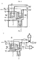
Fig. 1 , a battery pack connection circuit 1 is provided between the power conversion circuit and the main battery for the driving motor. The battery pack connection circuit 1 applies a charge current to the main battery from the driving motor (or generator) under generation mode and applies a driving current to the driving motor from the main battery under driving mode, so that the vehicle is driven by the electric energy. - To the battery pack connection circuit 1 are respectively connected a HV (-) lead and a HV (+) lead for applying the current to the power conversion circuit from the main battery, in a predetermined pattern. To an input terminal of the HV (+) lead is connected a
pre-charge resistor 2 for limiting a surge over-current applied to the power conversion circuit from the main battery when the vehicle is started. In addition, apre-charge relay 3 for high-voltage and arelay 4 for high-voltage main power supply capable of controlling the over-current are respectively connected between the pre-charge resistor and an output terminal through different routes. In the mean time, the HV (-) lead is provided with aseparate relay 4a for main power supply capable of controlling the over-current applied to the driving motor from the main battery. - The
relays pre-charge relay 3 are respectively provided with condensers connected through a control lead applied with 12V current from the main battery. The respective condensers are capable of turning on/off thecorresponding relays Figs. 1 and 2 ). - A similar circuit for the battery pack of a HEV or EV is known from
JP 2002-267698 - However, the battery back connection circuit of the conventional HEV or EV is not provided with warning means. Accordingly, even though the over-current flows or the over-voltage is applied to the high-voltage pre-charge resistor of the battery pack connection circuit and the pre-charge relay is under ON state, a driver cannot properly cope with the emergency situation. Further, the over-current flows to the power conversion circuit of the driving motor in the vehicle, thereby causing the smoothing capacitor to be damaged.
- Accordingly, the invention has been made to solve the above problems.
- An object of the invention is to prevent a smoothing capacitor or related devices of a power conversion circuit from being damaged in advance with a battery pack connection circuit arranged between a battery pack and the power conversion circuit through a battery management system (BMS) or vehicle control device when surge current is applied to the power conversion circuit of a vehicle motor unit from the battery pack in starting the vehicle with a start key.
- Another object of the invention is to notify a driver of a diagnosis result through warning means when over-current flows to a pre-charge resistor of the battery pack connection circuit or a pre-charge relay of the battery pack connection circuit is turned off due to over-current or over-voltage during the driving, thereby contributing to a safety drive of the vehicle.
- In order to achieve the above objects, there is provided a battery pack management method for HEV and EV, the method comprising steps of: applying power for a control signal to a relay of a battery pack connection circuit through a battery management system (BMS) or vehicle control device; detecting current or voltage from a pre-charge resistor of the battery pack connection circuit; comparing the detected current or voltage with standard correspondence information pre-stored in a memory unit of the BMS to determine whether the detected value is within a normal range of the battery pack; and carrying out a normal charging operation when the detected value is within the normal range as a result of the determination, otherwise turning off a pre-charge relay of the battery pack connection circuit and then providing a driver with a warning signal through warning means electrically connected to the BMS.
- The above and other objects, features and advantages of the present invention will be more apparent from the following detailed description taken in conjunction with the accompanying drawings, in which:
-
FIG. 1 is a view showing a HV relay control unit typically provided to a battery pack connection circuit of a battery pack; -
FIG. 2 shows a structure for measuring current and voltage of a battery pack, which is carried out at an output terminal of a HV relay control unit; and -
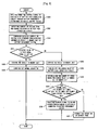
FIG. 3 is a flow chart showing a battery pack management method for HEV and EV according to an embodiment of the invention. - Hereinafter, a preferred embodiment of the present invention will be described with reference to the accompanying drawings. In the following description of the present invention, a detailed description of known functions and configurations incorporated - herein will be omitted when it may make the subject matter of the present invention rather unclear.
-
Fig. 3 is a flow chart showing a battery pack management method for HEV and EV according to an embodiment of the invention. - Hereinafter, it is described a battery pack management method for HEV and EV structured as described above, with reference to
Fig. 3 . - First, when a vehicle is started, power for a control signal is applied to
relays - Then, current or voltage is detected from a
pre-charge resistor 2 of the battery pack connection circuit 1 (S305). - Subsequently, the detected current or voltage is compared with standard correspondence information pre-stored in a memory unit (not shown) of the BMS (S310). Then, it is determined whether the detected value is within a normal range of the battery pack (S315).
- When the detected value is within the normal range as a result of the determination, a normal charging operation is carried out (S325), otherwise the
pre-charge relay 3 of the battery pack connection circuit is turned off (S335) and then a warning signal is provided to a driver through warning-means (not shown) electrically connected to the BMS(S350). - It is preferred that the comparison result of the measured value resulting from the determination step (S315) and the standard correspondence information is stored in the memory unit (S320, S330).
- In addition, the step of turning off the pre-charge relay (S335) is preferably carried out under state that a relay detection signal detected from the
pre-charge relay 3 stands by. - When the
pre-charge relay 3 is turned off, the over-current or over-voltage applied to a motor unit of the vehicle from the pre-charge relay is interrupted, so that a smoothing capacitor in the motor unit is safely protected from the over-current or over-voltage. - In the mean time, the warning means may be a display lamp or speaker and the display lamp is preferably provided to a dashboard of the vehicle.
- Continuously, when the pre-charge relay is turned off, the number of cases where the
pre-charge relay 3 is turned off is accumulated in the memory unit (S340). - Then, it is determined whether the accumulated number of cases where the
pre-charge relay 3 is turned off is within the number of cases where the pre-charge relay is allowed to be turned off, which is preset in the memory unit (S345). - When the accumulated off number of times is within the allowed off number of times as a result of the determination, the warning signal is provided to the driver through the warning means (S350). In the mean time, when the accumulated off number of times exceeds the allowed off number of times, the operation of the battery pack is interrupted (S335).
- As described above, according to the invention, when the surge current is applied to the power conversion circuit of the vehicle motor unit from the battery pack in starting the vehicle, a smoothing capacitor or related devices of the power conversion circuit is prevented from being damaged in advance through the battery pack connection circuit arranged between the battery pack and the power conversion circuit.
- In addition, when the over-current flows to the pre-charge resistor of the battery pack connection circuit or the pre-charge relay of the battery pack connection circuit is turned off due to the over-current or over-voltage during the driving, a diagnosis result is notified to the driver through the warning means, thereby contributing to a safety drive of the vehicle.
Claims (10)
- A battery pack management method for HEV and EV, the method comprising steps of:applying power for a control signal to a relay of a battery pack connection circuit through a battery management system (BMS) or vehicle control device;detecting current or voltage from a pre-charge resistor of the battery pack connection circuit;comparing the detected current or voltage with standard correspondence information pre-stored in a memory unit of the BMS to determine whether the detected value is within a normal range of the battery pack; andcarrying out a normal charging operation when the detected value is within the normal range as a result of the determination, otherwise turning off a pre-charge relay of the battery pack connection circuit and then providing a driver with a warning signal through warning means electrically connected to the BMS.
- The method according to claim 1, wherein a comparison result of the measured value resulting from the determination step and the standard correspondence information is stored in a memory unit.
- The method according to claim 1, wherein the step of turning off the pre-charge relay is carried out under state that a relay detection signal detected from the pre-charge relay stands by.
- The method according to claim 1, wherein in the step of turning off the pre-charge relay, when the pre-charge relay is turned off, over-current or over-voltage applied to a motor unit of a vehicle from the pre-charge relay is interrupted, so that a smoothing capacitor of a power conversion unit is prevented from being damaged in advance.
- The method according to claim 1, wherein the warning means is a display lamp or speaker.
- The method according to claim 5, wherein the display lamp is provided to a dashboard of the vehicle.
- The method according to claim 1, further comprising a step of accumulating the number of cases where the pre-charge relay is turned off in a memory unit between the step of turning off the pre-charge relay and the step of providing the warning signal.
- The method according to claim 7, further comprising determining whether the accumulated off number of times is within the number of cases where the pre-charge relay is allowed to be turned off, which is preset in the memory unit, after the accumulating step.
- The method according to claim 8, wherein when the accumulated off number of times is within the allowed off number of times as a result of the determination, the warning signal is provided to the driver through the warning means.
- The method according to claim 8, further comprising a step of interrupting an operation of the battery pack when the accumulated off number of times exceeds the allowed off number of times as a result of the determination.
Applications Claiming Priority (2)
| Application Number | Priority Date | Filing Date | Title |
|---|---|---|---|
| KR1020050033939A KR101091268B1 (en) | 2005-04-25 | 2005-04-25 | How to care for battery packs for HE and EV |
| PCT/KR2006/001463 WO2006115349A1 (en) | 2005-04-25 | 2006-04-19 | Battery pack management method for hev and ev |
Publications (3)
| Publication Number | Publication Date |
|---|---|
| EP1882284A1 EP1882284A1 (en) | 2008-01-30 |
| EP1882284A4 EP1882284A4 (en) | 2009-11-25 |
| EP1882284B1 true EP1882284B1 (en) | 2011-07-27 |
Family
ID=37214950
Family Applications (1)
| Application Number | Title | Priority Date | Filing Date |
|---|---|---|---|
| EP06747374A Expired - Lifetime EP1882284B1 (en) | 2005-04-25 | 2006-04-19 | Battery pack management method for hev and ev |
Country Status (7)
| Country | Link |
|---|---|
| US (1) | US7688023B2 (en) |
| EP (1) | EP1882284B1 (en) |
| JP (1) | JP4685158B2 (en) |
| KR (1) | KR101091268B1 (en) |
| CN (1) | CN101160686B (en) |
| TW (1) | TWI304028B (en) |
| WO (1) | WO2006115349A1 (en) |
Cited By (2)
| Publication number | Priority date | Publication date | Assignee | Title |
|---|---|---|---|---|
| FR3127845A1 (en) | 2021-10-06 | 2023-04-07 | Psa Automobiles Sa | JUNCTION BOX FOR MOTOR VEHICLE |
| US11996722B2 (en) | 2020-06-29 | 2024-05-28 | Dongguan Poweramp Technology Limited | Electrochemical apparatus, electrical apparatus, electric vehicle, and power supply control method |
Families Citing this family (48)
| Publication number | Priority date | Publication date | Assignee | Title |
|---|---|---|---|---|
| KR101091268B1 (en) * | 2005-04-25 | 2011-12-07 | 주식회사 엘지화학 | How to care for battery packs for HE and EV |
| KR101103616B1 (en) * | 2008-01-07 | 2012-01-09 | 에스케이이노베이션 주식회사 | Pre-Charge Protection Circuit Device Using Interlock Switch |
| JP5155701B2 (en) * | 2008-03-12 | 2013-03-06 | 富士重工業株式会社 | Vehicle power supply |
| CN102137772B (en) | 2008-09-01 | 2013-08-21 | 株式会社Lg化学 | Device and method for controlling switching unit between battery pack and load, battery pack and battery management device including the device |
| US20100163321A1 (en) * | 2008-12-30 | 2010-07-01 | Goff Sean K | Power converter module for a battery-operated vehicle |
| DE102009002018A1 (en) * | 2009-03-31 | 2010-10-07 | Robert Bosch Gmbh | Electrical circuit for the separation of batteries |
| EP2442074B1 (en) * | 2010-03-18 | 2016-03-16 | Toyota Jidosha Kabushiki Kaisha | Electrically driven vehicle |
| CN101841177B (en) * | 2010-04-23 | 2012-10-24 | 北汽福田汽车股份有限公司 | Method and system for protecting electric vehicle pre-charging circuit |
| WO2012005554A2 (en) * | 2010-07-09 | 2012-01-12 | (주)브이이엔에스 | Electric vehicle and method for controlling same |
| DE102010038892A1 (en) * | 2010-08-04 | 2012-02-09 | Robert Bosch Gmbh | Method for limiting an inrush current in an electrical network |
| DE102010041275B4 (en) * | 2010-09-23 | 2019-11-28 | Robert Bosch Gmbh | Procedure for checking the proper functioning of a current sensor |
| US8089249B2 (en) * | 2010-11-08 | 2012-01-03 | O2Micro, Inc. | Battery management systems and methods |
| CN102761167B (en) * | 2011-04-28 | 2015-02-18 | 大叶大学 | Battery management system for two-wheeled vehicle |
| CN102887200B (en) * | 2011-07-18 | 2014-06-25 | 凹凸电子(武汉)有限公司 | Electric bicycle control system and method |
| JP2013038871A (en) * | 2011-08-05 | 2013-02-21 | Sanyo Electric Co Ltd | Switching device |
| KR20130096481A (en) * | 2012-02-22 | 2013-08-30 | 에스케이이노베이션 주식회사 | Relay sequential control apparatus and method thereof |
| JP6029251B2 (en) | 2012-06-13 | 2016-11-24 | エルジー・ケム・リミテッド | Apparatus and method for estimating state of charge of secondary battery including mixed positive electrode material |
| JP2014053991A (en) * | 2012-09-05 | 2014-03-20 | Suzuki Motor Corp | Vehicle state alarming device |
| US9966584B2 (en) | 2013-03-11 | 2018-05-08 | Atieva, Inc. | Bus bar for battery packs |
| US9041454B2 (en) | 2013-03-15 | 2015-05-26 | Atieva, Inc. | Bias circuit for a switched capacitor level shifter |
| US10084214B2 (en) | 2013-03-15 | 2018-09-25 | Atieva, Inc. | Automatic switchover from cell voltage to interconnect voltage monitoring |
| US10901019B2 (en) * | 2013-03-15 | 2021-01-26 | Atieva, Inc. | Method of connecting cell voltage sensors |
| US10063071B2 (en) | 2013-03-15 | 2018-08-28 | Atieva, Inc. | Balance resistor and low pass filter |
| CN103342100B (en) * | 2013-07-23 | 2015-08-26 | 北京经纬恒润科技有限公司 | A kind of power on method for supervising and system of electronlmobil |
| KR101614202B1 (en) | 2013-08-28 | 2016-04-21 | 주식회사 엘지화학 | Current measurement relay apparatus |
| US9383416B2 (en) | 2013-08-30 | 2016-07-05 | Ford Global Technologies, Llc | System and method for testing vehicle traction battery components |
| KR101591150B1 (en) * | 2013-10-31 | 2016-02-02 | 주식회사 엘지화학 | Application module control and hardware call apparatus for standardization of battery |
| US9209635B2 (en) | 2013-12-02 | 2015-12-08 | Lg Chem, Ltd. | Pre-charging system for a capacitor in a voltage inverter for an electric motor |
| US9214888B2 (en) * | 2013-12-20 | 2015-12-15 | Lg Chem, Ltd. | Pre-charging system for a capacitor in a voltage inverter for an electric motor |
| KR101551035B1 (en) * | 2013-12-30 | 2015-09-08 | 현대자동차주식회사 | Method for diagnosing breakdown during pre-charging |
| CN103762398A (en) * | 2014-01-16 | 2014-04-30 | 北京智行鸿远汽车技术有限公司 | Low-temperature heating system of power battery and control method of system |
| EP2945243B1 (en) * | 2014-02-20 | 2020-08-12 | LG Chem, Ltd. | Apparatus, system and method for preventing damage to battery rack by means of voltage measurement |
| KR101575461B1 (en) * | 2014-03-14 | 2015-12-07 | 현대자동차주식회사 | Method for precharge resistance fail-safe of hybrid vehicle |
| US9413184B2 (en) | 2014-03-21 | 2016-08-09 | Lg Chem, Ltd. | Pre-charging and voltage supply system for a DC-AC inverter |
| US9748768B2 (en) | 2014-03-21 | 2017-08-29 | Lg Chem, Ltd. | Pre-charging and voltage supply system for a DC-AC inverter |
| US9537333B2 (en) | 2014-04-22 | 2017-01-03 | Lg Chem, Ltd. | Voltage supply system and method for disabling operation of a DC-DC voltage converter |
| CN105270181B (en) * | 2014-06-25 | 2017-08-22 | 广州汽车集团股份有限公司 | Electric control method under auxiliary reclay control device and its control method, high pressure |
| KR102292613B1 (en) * | 2014-10-02 | 2021-08-23 | 에스케이이노베이션 주식회사 | Overcharge protection apparatus and method including diagnostic function |
| CN104483614B (en) * | 2014-12-22 | 2017-08-25 | 重庆长安汽车股份有限公司 | A kind of pre-charge resistance durability test method and system |
| CN104626959B (en) * | 2015-01-30 | 2017-02-01 | 吉林建筑大学 | Hybrid electric vehicle system and energy management strategy thereof |
| CN104836294B (en) * | 2015-05-08 | 2018-03-16 | 深圳市英威腾电动汽车驱动技术有限公司 | A kind of charge control method of pre-charge circuit |
| CN105914730A (en) * | 2016-06-06 | 2016-08-31 | 东风柳州汽车有限公司 | Vehicle-mounted-charger reverse connection prevention method |
| KR102311510B1 (en) * | 2016-11-02 | 2021-10-08 | 삼성에스디아이 주식회사 | Battery pack |
| KR102256101B1 (en) * | 2018-01-30 | 2021-05-25 | 주식회사 엘지에너지솔루션 | Apparatus for diagnosing pre-charge circuit unit |
| EP3890134B1 (en) * | 2018-11-28 | 2024-03-06 | Mitsubishi Electric Corporation | Power control system |
| CN111791749B (en) * | 2019-03-19 | 2021-11-23 | 上海汽车集团股份有限公司 | Pre-charging control method and device |
| EP4070982A1 (en) | 2021-04-08 | 2022-10-12 | Nxp B.V. | Systems and methods for increasing degraded torque availability |
| CN113922443A (en) * | 2021-09-13 | 2022-01-11 | 东风柳州汽车有限公司 | Charging control circuit, method, device and equipment for electric automobile |
Family Cites Families (16)
| Publication number | Priority date | Publication date | Assignee | Title |
|---|---|---|---|---|
| FR2518757B1 (en) * | 1981-12-19 | 1986-11-07 | Bosch Gmbh Robert | METHOD AND DEVICE FOR VERIFYING THE CHARGE STATE OF A VEHICLE BATTERY |
| KR960027134A (en) * | 1994-12-22 | 1996-07-22 | 김광호 | Charging device having a recharge prevention function of a full charge battery and its control method |
| JP3536581B2 (en) * | 1997-04-16 | 2004-06-14 | 日産自動車株式会社 | Power generation control device for hybrid electric vehicle |
| JP3736933B2 (en) * | 1997-04-23 | 2006-01-18 | 本田技研工業株式会社 | Electric vehicle control device |
| US6181101B1 (en) * | 1999-03-12 | 2001-01-30 | Yazaki Corporation | Intelligent junction box |
| US6091325A (en) * | 1999-09-24 | 2000-07-18 | Battery Alert Ltd. | Device and method for warning of vehicle battery deterioration |
| JP3668145B2 (en) * | 2001-03-09 | 2005-07-06 | 三洋電機株式会社 | Current detector |
| JP3685105B2 (en) * | 2001-08-08 | 2005-08-17 | 日産自動車株式会社 | Apparatus and method for calculating output deterioration of secondary battery |
| JP3764672B2 (en) * | 2001-10-30 | 2006-04-12 | 本田技研工業株式会社 | Working machine |
| JP4248854B2 (en) * | 2002-11-22 | 2009-04-02 | パナソニック株式会社 | Battery management system and battery pack |
| JP3963155B2 (en) * | 2003-07-31 | 2007-08-22 | トヨタ自動車株式会社 | Power supply control device, power output device including the same, and automobile |
| KR100488741B1 (en) * | 2003-08-27 | 2005-05-11 | 현대자동차주식회사 | Method for dc link line pre-charge monitor and conclusion on motor control unit of electric vehicle |
| JP2006056654A (en) * | 2004-08-19 | 2006-03-02 | Fuji Xerox Co Ltd | Paper ejector |
| JP4116609B2 (en) * | 2004-11-04 | 2008-07-09 | パナソニックEvエナジー株式会社 | Power supply control device, electric vehicle and battery control unit |
| JP2006238509A (en) * | 2005-02-22 | 2006-09-07 | Panasonic Ev Energy Co Ltd | Control device of electric vehicle, control method of the electric vehicle, program and computer-readable recording medium |
| KR101091268B1 (en) * | 2005-04-25 | 2011-12-07 | 주식회사 엘지화학 | How to care for battery packs for HE and EV |
-
2005
- 2005-04-25 KR KR1020050033939A patent/KR101091268B1/en not_active Expired - Lifetime
-
2006
- 2006-04-19 JP JP2008508744A patent/JP4685158B2/en not_active Expired - Lifetime
- 2006-04-19 TW TW095113943A patent/TWI304028B/en active
- 2006-04-19 CN CN2006800128047A patent/CN101160686B/en not_active Expired - Lifetime
- 2006-04-19 WO PCT/KR2006/001463 patent/WO2006115349A1/en not_active Ceased
- 2006-04-19 EP EP06747374A patent/EP1882284B1/en not_active Expired - Lifetime
- 2006-04-24 US US11/409,571 patent/US7688023B2/en active Active
Cited By (2)
| Publication number | Priority date | Publication date | Assignee | Title |
|---|---|---|---|---|
| US11996722B2 (en) | 2020-06-29 | 2024-05-28 | Dongguan Poweramp Technology Limited | Electrochemical apparatus, electrical apparatus, electric vehicle, and power supply control method |
| FR3127845A1 (en) | 2021-10-06 | 2023-04-07 | Psa Automobiles Sa | JUNCTION BOX FOR MOTOR VEHICLE |
Also Published As
| Publication number | Publication date |
|---|---|
| KR20060111946A (en) | 2006-10-31 |
| JP4685158B2 (en) | 2011-05-18 |
| WO2006115349A1 (en) | 2006-11-02 |
| EP1882284A4 (en) | 2009-11-25 |
| CN101160686B (en) | 2010-05-19 |
| US20060255766A1 (en) | 2006-11-16 |
| TWI304028B (en) | 2008-12-11 |
| KR101091268B1 (en) | 2011-12-07 |
| EP1882284A1 (en) | 2008-01-30 |
| TW200700256A (en) | 2007-01-01 |
| CN101160686A (en) | 2008-04-09 |
| US7688023B2 (en) | 2010-03-30 |
| JP2008538892A (en) | 2008-11-06 |
Similar Documents
| Publication | Publication Date | Title |
|---|---|---|
| EP1882284B1 (en) | Battery pack management method for hev and ev | |
| EP3046198B1 (en) | Electric power storage system | |
| US9071081B2 (en) | Power source device for vehicle | |
| JP4116609B2 (en) | Power supply control device, electric vehicle and battery control unit | |
| KR100812745B1 (en) | A computer-readable recording medium storing a voltage generating device, an automobile, a control method for a voltage generating device, an automotive control method, and a program for executing the control method with a computer. | |
| CN102811887B (en) | Vehicle power source device | |
| US8552682B2 (en) | Battery charging system for hybrid vehicles | |
| US9929674B2 (en) | Power supply system for vehicle | |
| CN104995524B (en) | Method for testing accumulators in motor vehicles | |
| KR20140036039A (en) | Vehicle battery control device | |
| CN105556320A (en) | Method for detecting disconnection of a power supply battery of a motor vehicle | |
| EP3411934B1 (en) | Integrated battery safety interlock | |
| JP5154306B2 (en) | Vehicle power supply | |
| JP2003199385A (en) | Countermeasure against demagnetization of electric vehicle | |
| JP2003180001A (en) | Apparatus and method for preventing deterioration of motor of electric vehicle | |
| CN102725935B (en) | Device and method for detecting polarity reversal on the low-voltage side of a DC voltage converter in a dual-voltage vehicle electrical system | |
| US20140288803A1 (en) | Vehicle With Engine Start-Stop Device and Method of Operating Same | |
| JP2013189161A (en) | Hybrid vehicle and electric power supply method for hybrid vehicle | |
| JP2011017546A (en) | Device and method for diagnosing deterioration of lead battery for vehicle | |
| KR20150042033A (en) | Dark current monitoring system for hybrid electric vehicle and method thereof | |
| KR101631237B1 (en) | A high voltage electricity generation control system for in-use vehicles | |
| JP2019129665A (en) | Power supply device for vehicle | |
| EP4503260A1 (en) | Hybrid system | |
| JP2005218284A (en) | Current sensor | |
| JP2026025108A (en) | Power Supply Control System |
Legal Events
| Date | Code | Title | Description |
|---|---|---|---|
| PUAI | Public reference made under article 153(3) epc to a published international application that has entered the european phase |
Free format text: ORIGINAL CODE: 0009012 |
|
| 17P | Request for examination filed |
Effective date: 20071120 |
|
| AK | Designated contracting states |
Kind code of ref document: A1 Designated state(s): DE FR GB |
|
| DAX | Request for extension of the european patent (deleted) | ||
| RBV | Designated contracting states (corrected) |
Designated state(s): DE FR GB |
|
| A4 | Supplementary search report drawn up and despatched |
Effective date: 20091026 |
|
| 17Q | First examination report despatched |
Effective date: 20100216 |
|
| GRAP | Despatch of communication of intention to grant a patent |
Free format text: ORIGINAL CODE: EPIDOSNIGR1 |
|
| GRAS | Grant fee paid |
Free format text: ORIGINAL CODE: EPIDOSNIGR3 |
|
| GRAA | (expected) grant |
Free format text: ORIGINAL CODE: 0009210 |
|
| AK | Designated contracting states |
Kind code of ref document: B1 Designated state(s): DE FR GB |
|
| REG | Reference to a national code |
Ref country code: GB Ref legal event code: FG4D |
|
| REG | Reference to a national code |
Ref country code: DE Ref legal event code: R096 Ref document number: 602006023345 Country of ref document: DE Effective date: 20110915 |
|
| PLBE | No opposition filed within time limit |
Free format text: ORIGINAL CODE: 0009261 |
|
| STAA | Information on the status of an ep patent application or granted ep patent |
Free format text: STATUS: NO OPPOSITION FILED WITHIN TIME LIMIT |
|
| 26N | No opposition filed |
Effective date: 20120502 |
|
| REG | Reference to a national code |
Ref country code: DE Ref legal event code: R097 Ref document number: 602006023345 Country of ref document: DE Effective date: 20120502 |
|
| REG | Reference to a national code |
Ref country code: FR Ref legal event code: PLFP Year of fee payment: 10 |
|
| REG | Reference to a national code |
Ref country code: FR Ref legal event code: PLFP Year of fee payment: 11 |
|
| REG | Reference to a national code |
Ref country code: FR Ref legal event code: PLFP Year of fee payment: 12 |
|
| REG | Reference to a national code |
Ref country code: FR Ref legal event code: PLFP Year of fee payment: 13 |
|
| REG | Reference to a national code |
Ref country code: DE Ref legal event code: R081 Ref document number: 602006023345 Country of ref document: DE Owner name: LG ENERGY SOLUTION LTD., KR Free format text: FORMER OWNER: LG CHEM. LTD., SEOUL, KR Ref country code: DE Ref legal event code: R081 Ref document number: 602006023345 Country of ref document: DE Owner name: LG ENERGY SOLUTION, LTD., KR Free format text: FORMER OWNER: LG CHEM. LTD., SEOUL, KR |
|
| P01 | Opt-out of the competence of the unified patent court (upc) registered |
Effective date: 20230512 |
|
| REG | Reference to a national code |
Ref country code: GB Ref legal event code: 732E Free format text: REGISTERED BETWEEN 20230824 AND 20230831 |
|
| REG | Reference to a national code |
Ref country code: DE Ref legal event code: R081 Ref document number: 602006023345 Country of ref document: DE Owner name: LG ENERGY SOLUTION, LTD., KR Free format text: FORMER OWNER: LG ENERGY SOLUTION LTD., SEOUL, KR |
|
| PGFP | Annual fee paid to national office [announced via postgrant information from national office to epo] |
Ref country code: FR Payment date: 20250321 Year of fee payment: 20 |
|
| PGFP | Annual fee paid to national office [announced via postgrant information from national office to epo] |
Ref country code: GB Payment date: 20250320 Year of fee payment: 20 |
|
| PGFP | Annual fee paid to national office [announced via postgrant information from national office to epo] |
Ref country code: DE Payment date: 20250320 Year of fee payment: 20 |
|
| REG | Reference to a national code |
Ref country code: DE Ref legal event code: R071 Ref document number: 602006023345 Country of ref document: DE |