EP1881252A1 - Sicherungsvorrichtung für ein Sicherungselement - Google Patents
Sicherungsvorrichtung für ein Sicherungselement Download PDFInfo
- Publication number
- EP1881252A1 EP1881252A1 EP07033507A EP07033507A EP1881252A1 EP 1881252 A1 EP1881252 A1 EP 1881252A1 EP 07033507 A EP07033507 A EP 07033507A EP 07033507 A EP07033507 A EP 07033507A EP 1881252 A1 EP1881252 A1 EP 1881252A1
- Authority
- EP
- European Patent Office
- Prior art keywords
- securing element
- securing
- springs
- receiving body
- openings
- Prior art date
- Legal status (The legal status is an assumption and is not a legal conclusion. Google has not performed a legal analysis and makes no representation as to the accuracy of the status listed.)
- Granted
Links
Images


Classifications
-
- F—MECHANICAL ENGINEERING; LIGHTING; HEATING; WEAPONS; BLASTING
- F16—ENGINEERING ELEMENTS AND UNITS; GENERAL MEASURES FOR PRODUCING AND MAINTAINING EFFECTIVE FUNCTIONING OF MACHINES OR INSTALLATIONS; THERMAL INSULATION IN GENERAL
- F16L—PIPES; JOINTS OR FITTINGS FOR PIPES; SUPPORTS FOR PIPES, CABLES OR PROTECTIVE TUBING; MEANS FOR THERMAL INSULATION IN GENERAL
- F16L37/00—Couplings of the quick-acting type
- F16L37/08—Couplings of the quick-acting type in which the connection between abutting or axially overlapping ends is maintained by locking members
- F16L37/12—Couplings of the quick-acting type in which the connection between abutting or axially overlapping ends is maintained by locking members using hooks, pawls, or other movable or insertable locking members
- F16L37/14—Joints secured by inserting between mating surfaces an element, e.g. a piece of wire, a pin, a chain
- F16L37/142—Joints secured by inserting between mating surfaces an element, e.g. a piece of wire, a pin, a chain where the securing element is inserted tangentially
- F16L37/144—Joints secured by inserting between mating surfaces an element, e.g. a piece of wire, a pin, a chain where the securing element is inserted tangentially the securing element being U-shaped
Definitions
- the invention relates to a securing device for a securing element for fixing an element in a receptacle, preferably a conduit in a passage of a receiving body.
- the DE 199 46 260 C1 shows a quick coupling, engage in the projections of a locking element in recesses in the clutch housing 1. To pull out the locking element, the locking element is compressed itself. For this purpose, a force in 2 directions (compression clamp, perpendicular to the pulling out) is necessary.
- the DE 10 2004 062 207 B3 shows a rectangular opening for receiving a fuse element, which can not be dismantled without destruction.
- the invention has for its object to secure a lock and latching-free fixation of an element in a receptacle, preferably a pipeline of a pressure-less and / or pressure-guided system in a receiving body, in place and location, the securing device on the one hand be captive and on the other hand easily applicable should.
- springs are connected in one piece as a securing device with the receiving body, wherein the springs lock the securing element in a form-fitting manner.
- the springs are in the untensioned state in the displacement of the fuse element.
- the securing element is received both in openings in the receiving body and also guides removed therefrom that forces can be transmitted via the securing element to the receiving body.
- FIG. 1 shows a receiving body 1 in which a line 9 is fastened.
- the line 9 has a ring 10 with a groove for receiving a securing element 11, here in the form of a wire clip.
- a line 9 with ring 10 including the groove for receiving the securing element 11 is in principle from the patent application AT A 219/2006 known.
- receiving body 1 On receiving body 1 there are springs 2 with stops 3, wherein receiving body 1, springs 2 and stops 3 form a single component.
- receiving body 1 In the receiving body 1 are cylindrical openings 18 in which the securing element 11 is inserted and thus secures the ring 10 in an axial position. In front of the securing element 11 are partially the springs 2 with the stops. 3
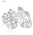
- FIG. 2 shows the same receiving body 1 without a line 9. It can be seen that the securing element 11 is held both in the cylindrical openings 18 and in guides 8.
- a passage 7 which has a round geometry in this case.
- the guides 8 extend axially on the same line as the cylindrical openings 18 and are in this case with respect to the cylindrical openings 18 on the other side of the passage 7.
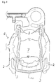
- Figure 3 shows the receiving body 1 without line 9 from above including securing element eleventh
- Figure 4 shows a section thereof from the passage 7 in the receiving body 1 in section. It can be seen that the securing element 11 is received both in the openings 18 and in the guides 8. On the side of the openings 18 outside the passage 7 are the springs 2 with the rounded stops 3. The stops 3 are located partially in front of the openings 18, so that the securing element 11 is secured against falling out. The securing element 11 can move in this position from the direct concern to the material of the receiving body 1 to the attacks 3, resulting in a game S.
- the securing element 11 has constrictions 12, so that when inserting the securing element 11, a ring 10 located in the passage is bracketed behind its thickest point.
- the fuse element 11 is pulled out. It is necessary that by appropriate application of force on the rounded stops 3 of the springs 2, these are pressed outwards, so that the securing element 11 can overcome the lock. Due to the round shape of the stops 3 a force is exerted on the springs 2 when pulling out the securing element 11, which allows an opening of the springs 2 perpendicular to the direction of movement of the securing element 11. However, this presupposes that the axial force for pulling out the securing element 11 is so great that the force required to sufficiently open the springs 2 is overcome. Once the fuse element 11 releases the ring 10, the line 9 can be pulled out.
- the locking of fuse elements according to the invention is not limited to the fixation of lines in receiving bodies, but can also be used for other fixings.
- sensors can be secured in a holder.
- the stops 3 can also have planes which are arranged at an acute angle to the direction of movement of the securing element 11. It is relevant that by an axial displacement of the securing element 11, a force perpendicular to this axial displacement for opening the springs 2 is applied.
Landscapes
- Engineering & Computer Science (AREA)
- General Engineering & Computer Science (AREA)
- Mechanical Engineering (AREA)
- Fuses (AREA)
- Clamps And Clips (AREA)
- Quick-Acting Or Multi-Walled Pipe Joints (AREA)
Abstract
Description
- Die Erfindung bezieht sich auf eine Sicherungsvorrichtung für ein Sicherungselement zur Fixierung eines Elements in einer Aufnahme, vorzugsweise einer Leitung in einem Durchlass eines Aufnahmekörpers.
- In der Heizungstechnik werden vorwiegend wasserführende Leitungen mittels Sicherungselementen in einem Aufnahmekörper fixiert, wobei das Sicherungselement nicht oder mittels einer gesonderten Sicherungsvorrichtung gesichert wird. Wird das Sicherungselement nicht gesichert, so kann es zu einer unbeabsichtigten Demontage kommen. Bei einer Sicherung wird zumeist das montierte Sicherungselement durch nachträgliches Befestigen der Sicherungsvorrichtung abgesichert. Zur Demontage des Sicherungselementes ist es dann meist notwendig, ein Werkzeug zu benutzen.
- Die
DE 199 46 260 C1 zeigt eine Schnellkupplung, bei der Vorsprünge eines Verriegelungselements in Vertiefungen im Kupplungsgehäuse 1 einrasten. Zum Herausziehen des Verriegelungselements wird das Verriegelungselement selbst zusammengedrückt. Hierzu ist eine Kraftaufwendung in 2 Richtungen (Zusammendrücken Klammer, senkrecht dazu das Herausziehen) notwendig. - Die
DE 10 2004 062 207 B3 zeigt eine rechteckige Öffnung zur Aufnahme eines Sicherungselements, welches nicht mehr zerstörungsfrei demontiert werden kann. - Die aus oben genanntem Stand der Technik bekannten Sicherungselemente stellen sicher, dass eine unbeabsichtigte Demontage verhindert wird. Dies ist jedoch in vielen Fällen nicht notwendig da die Verbindungen an Stellen positioniert sind, die vor unbeabsichtigtem Eingriff geschützt sind. In diesen Fällen genügt eine Sicherung, die einfach gelöst werden kann. Eine Kraftaufwendung in zwei Richtungen wie in der
DE 199 46 260 C1 beschrieben, ist dann eher hinderlich. - Der Erfindung liegt die Aufgabe zugrunde, eine verriegelungs- und verrastungsfreie Fixierung eines Elements in einer Aufnahme, vorzugsweise einer Rohrleitung eines drucklosen und / oder druckgeführten Systems in einem Aufnahmekörper, in Ort und Lage zu sichern, wobei die Sicherungsvorrichtung einerseits unverlierbar und andererseits leicht anwendbar sein soll.
- Erfindungsgemäß wird dies gemäß den Merkmalen des Anspruchs 1 dadurch erreicht, dass Federn als Sicherungsvorrichtung mit dem Aufnahmekörper einstückig verbunden sind, wobei die Federn das Sicherungselement formschlüssig arretieren. Die Federn befinden sich dabei im ungespannten Zustand im Verschiebeweg des Sicherungselementes.
- Gemäß den Merkmalen des abhängigen Anspruchs 2 ergibt sich der Vorteil, dass die formschlüssige Arretierung reversibel überwunden werden kann, so dass das Sicherungselement wieder entfernt werden kann.
- Gemäß den Merkmalen des abhängigen Anspruchs 3 wird das Sicherungselement sowohl in Öffnungen im Aufnahmekörper als auch davon entfernten Führungen aufgenommen, so dass Kräfte über das Sicherungselement auf den Aufnahmekörper übertragen werden können.
- Die Erfindung wird nun anhand der Figuren detailliert erläutert. Hierbei zeigen
- Figur 1
- einen Aufnahmekörper mit erfindungsgemäßer Sicherungsvorrichtung, durch welche ein Rohr gesichert ist,
- Figur 2
- denselben Aufnahmekörper ohne das zu sichernde Rohr,
- Figur 3
- denselben Aufnahmekörper aus einer anderen Perspektive sowie
- Figur 4
- ein Detail hieraus.
- Figur 1 zeigt einen Aufnahmekörper 1, in welchem eine Leitung 9 befestigt ist. Die Leitung 9 verfügt über einen Ring 10 mit Nut zur Aufnahme eines Sicherungselements 11, hier in Form eines Drahtclips. Eine derartige Leitung 9 mit Ring 10 inklusive Nut zur Aufnahme des Sicherungselementes 11 ist prinzipiell aus der Patentanmeldung
AT A 219/2006 - Am Aufnahmekörper 1 befinden sich Federn 2 mit Anschlägen 3, wobei Aufnahmekörper 1, Federn 2 und Anschläge 3 ein einziges Bauteil bilden. Hierzu ist insbesondere ein Kunststoff-Spritzgussteil geeignet. Im Aufnahmekörper 1 befinden sich zylindrische Öffnungen 18, in denen das Sicherungselement 11 eingeschoben ist und somit den Ring 10 in axialer Lage sichert. Vor dem Sicherungselement 11 befinden sich partiell die Federn 2 mit den Anschlägen 3.
- Figur 2 zeigt denselben Aufnahmekörper 1 ohne Leitung 9. Es ist zu erkennen, dass das Sicherungselement 11 sowohl in den zylindrischen Öffnungen 18 als auch in Führungen 8 gehalten ist. Zur Aufnahme der Leitung 9 dient ein Durchlass 7, der in diesem Fall eine runde Geometrie aufweist. Besonders in einem derartigen Fall ist es vorteilhaft, wenn die Führungen 8 sich axial auf der gleichen Linie erstrecken wie die zylindrischen Öffnungen 18 und sich hierbei bezüglich der zylindrischen Öffnungen 18 auf der anderen Seite des Durchlasses 7 befinden.
- Figur 3 zeigt den Aufnahmekörper 1 ohne Leitung 9 von oben inklusive Sicherungselement 11.
- Figur 4 zeigt Ausschnittsweise hieraus den Durchlass 7 in dem Aufnahmekörper 1 im Schnitt. Es ist zu erkennen, dass das Sicherungselement 11 sowohl in den Öffnungen 18, als auch in den Führungen 8 aufgenommen wird. Auf der Seite der Öffnungen 18 außerhalb des Durchlasses 7 befinden sich die Federn 2 mit den abgerundeten Anschlägen 3. Die Anschläge 3 befinden sich partiell vor den Öffnungen 18, so dass das Sicherungselement 11 gegen Herausfallen gesichert ist. Das Sicherungselement 11 kann sich in dieser Position vom direkten Anliegen an das Material des Aufnahmekörpers 1 bis zu den Anschlägen 3 bewegen, wodurch sich ein Spiel S ergibt. Das Sicherungselement 11 verfügt über Einschnürungen 12, so dass beim Einschieben des Sicherungselementes 11 ein in dem Durchlass befindlicher Ring 10 hinter seiner dicksten Stelle eingeklammert wird.
- Zur Montage der Leitung 9 wird diese mit ihrem Ring 10 in die Durchführung 7 bis zu einem Anschlag eingeschoben. Sodann wird das Sicherungselement 11 durch die Anschläge 3 der Feder 2 gedrückt, wodurch die Federn 2 elastisch nach außen gedrückt werden. Das Sicherungselement 11 greift in den Ring 10 der Leitung 9 ein. Das hintere Ende des Sicherungselementes 11 greift in die Führungen 8 ein. Sobald das gesamte Sicherungselement 11 die Anschläge 3 der Federn 2 passiert hat, federn die Federn 2 in ihre unbelastete Position zurück, wodurch die Anschläge 3 das Sicherungselement 11 arretiert.
- Wird im Betrieb die Leitung 9 axial belastet, so werden die Aufnahmekräfte über den Ring 10 auf das Aufnahmeelement 11 und von diesem über die Auflageflächen in den zylindrischen Öffnungen 18, als auch den Führungen 8 auf den Aufnahmekörper 1 übertragen.
- Soll die Leitung 9 demontiert werden, so wird das Sicherungselement 11 herausgezogen. Hierbei ist es notwendig, dass durch entsprechende Kraftaufwendung auf die abgerundeten Anschlägen 3 der Federn 2 diese nach außen gedrückt werden, so dass das Sicherungselement 11 die Arretierung überwinden kann. Durch die runde Form der Anschläge 3 wird beim Herausziehen des Sicherungselements 11 eine Kraft auf die Federn 2 ausgeübt, welche eine Öffnung der Federn 2 senkrecht zur Bewegungsrichtung des Sicherungselements 11 ermöglicht. Dies setzt jedoch voraus, dass die axiale Kraft zum Herausziehen des Sicherungselements 11 derartig groß ist, dass die notwendige Kraft zum ausreichenden Öffnen der Federn 2 überwunden wird. Sobald das Sicherungselement 11 den Ring 10 freigibt, kann die Leitung 9 herausgezogen werden.
- Die erfindungsgemäße Arretierung von Sicherungselementen ist nicht nur auf die Fixierung von Leitungen in Aufnahmekörpern beschränkt, sondern kann auch für andere Fixierungen Anwendung finden. So können beispielsweise Sensoren in einer Halterung gesichert werden.
- Ferner können die Anschläge 3 auch über Ebenen, welche spitzwinklig zur Bewegungsrichtung des Sicherungselements 11 angeordnet sind verfügen. Relevant ist dass durch eine Axialverschiebung des Sicherungselements 11 eine Kraft senkrecht zu dieser Axialverschiebung zum Öffnen der Federn 2 aufgebracht wird.
Claims (3)
- Sicherungsvorrichtung für ein Sicherungselement (11) zur Fixierung eines Elements in einer Aufnahme mit Durchlass (7), vorzugsweise einer Leitung (9) in diesem Durchlass (7), eines Aufnahmekörpers (1), wobei das Sicherungselement (11) durch im wesentlichen zylindrische Öffnungen (18) in dem Aufnahmekörper (1) geführt wird, dadurch gekennzeichnet, dass mit dem Aufnahmekörper (1) einstückig Federn (2) außerhalb des Durchlasses (7) verbunden sind, wobei die Federn (2) das in den Öffnungen (18) eingeschobene Sicherungselement (11) formschlüssig arretieren, indem sie im ungespannten Zustand in den durch die im wesentlichen zylindrischen Öffnungen (18) bestimmten Verschiebeweg des Sicherungselements (11) hineinragen und die Federn (2) über Anschläge (3) verfügen, welche runde oder spitzwinklig zur Bewegungsrichtung des Sicherungselementes (11) angeordnete Berührflächen besitzen.
- Sicherungsvorrichtung für ein Sicherungselement (11) zur Fixierung eines Elements nach Anspruch 1, dadurch gekennzeichnet, dass die Federn (2) derart elastisch sind, dass die formschlüssige Arretierung durch Krafteinwirkung reversibel überwunden werden kann.
- Sicherungsvorrichtung für ein Sicherungselement (11) zur Fixierung eines Elements nach Anspruch 1 oder 2, dadurch gekennzeichnet, dass der Aufnahmekörper (1) über den Öffnungen (18) in axialer Richtung im Durchlass (7) gegenüberliegenden Führungen (8), welche das in die Öffnungen (18) eingeschobene Sicherungselement (11) führen, verfügen, das Sicherungselement (11) im arretierten Zustand über Spiel (S) verfügt und in jeder gesicherten Lage sowohl in den Öffnungen (18), als auch in den Führungen (8) anliegt.
Applications Claiming Priority (1)
| Application Number | Priority Date | Filing Date | Title |
|---|---|---|---|
| AT12112006A AT503989B1 (de) | 2006-07-17 | 2006-07-17 | Sicherungsvorrichtung für ein sicherungselement |
Publications (2)
| Publication Number | Publication Date |
|---|---|
| EP1881252A1 true EP1881252A1 (de) | 2008-01-23 |
| EP1881252B1 EP1881252B1 (de) | 2013-09-11 |
Family
ID=38421432
Family Applications (1)
| Application Number | Title | Priority Date | Filing Date |
|---|---|---|---|
| EP20070033507 Not-in-force EP1881252B1 (de) | 2006-07-17 | 2007-07-11 | Sicherungsvorrichtung für ein Sicherungselement |
Country Status (3)
| Country | Link |
|---|---|
| EP (1) | EP1881252B1 (de) |
| AT (1) | AT503989B1 (de) |
| DE (1) | DE102007032194B4 (de) |
Citations (3)
| Publication number | Priority date | Publication date | Assignee | Title |
|---|---|---|---|---|
| DE19603506A1 (de) * | 1996-02-01 | 1997-06-12 | Fichtel & Sachs Ag | Lösbare Steckverbindung |
| US20020070549A1 (en) * | 2000-12-08 | 2002-06-13 | Oscar Romero | One piece quick connector |
| DE10346712A1 (de) * | 2003-10-08 | 2005-05-19 | Henn Gmbh & Co. Kg | Steckverbindung für Rohr- und Schlauchleitungen mit Rastfederführung |
Family Cites Families (2)
| Publication number | Priority date | Publication date | Assignee | Title |
|---|---|---|---|---|
| DE19946260C1 (de) * | 1999-09-27 | 2001-01-11 | Itt Mfg Enterprises Inc | Schnellkupplung für Schläuche oder Rohrleitungen in Kraftfahrzeugen |
| DE102004062207B3 (de) * | 2004-12-23 | 2005-10-20 | Kirchner Fraenk Rohr | Verbindungseinrichtung |
-
2006
- 2006-07-17 AT AT12112006A patent/AT503989B1/de not_active IP Right Cessation
-
2007
- 2007-07-11 DE DE200710032194 patent/DE102007032194B4/de not_active Expired - Fee Related
- 2007-07-11 EP EP20070033507 patent/EP1881252B1/de not_active Not-in-force
Patent Citations (3)
| Publication number | Priority date | Publication date | Assignee | Title |
|---|---|---|---|---|
| DE19603506A1 (de) * | 1996-02-01 | 1997-06-12 | Fichtel & Sachs Ag | Lösbare Steckverbindung |
| US20020070549A1 (en) * | 2000-12-08 | 2002-06-13 | Oscar Romero | One piece quick connector |
| DE10346712A1 (de) * | 2003-10-08 | 2005-05-19 | Henn Gmbh & Co. Kg | Steckverbindung für Rohr- und Schlauchleitungen mit Rastfederführung |
Also Published As
| Publication number | Publication date |
|---|---|
| DE102007032194B4 (de) | 2014-09-04 |
| DE102007032194A1 (de) | 2008-01-24 |
| AT503989B1 (de) | 2008-10-15 |
| AT503989A1 (de) | 2008-02-15 |
| EP1881252B1 (de) | 2013-09-11 |
Similar Documents
| Publication | Publication Date | Title |
|---|---|---|
| DE3215015C2 (de) | Halteclip aus hartelastischem Kunststoff | |
| DE102015114696B4 (de) | Halterahmen für Steckverbindermodule | |
| CH667139A5 (de) | Verbindungsbeschlag. | |
| DE29800379U1 (de) | Befestigungselement | |
| DE2622269B2 (de) | Anschlußeinrichtung zwischen einem Kunststoffrohr und einem stationären Anschlußstutzen | |
| DE3001414A1 (de) | Einzelteil-montageanordnung | |
| CH667506A5 (de) | Drehbare schnappverbindung fuer rohrleitungen. | |
| DE102014103535A1 (de) | Vorrichtung zur Befestigung eines Bauteils an einem Trägerbauteil | |
| DE102018108830A1 (de) | System aus einem Anbauteil und einem Halteelement | |
| DE102016124805B4 (de) | Membranventil | |
| DE19852395C2 (de) | Steckkupplung | |
| DE3705610A1 (de) | Loesbare steckverbindung fuer rohrleitungen | |
| EP1375993B1 (de) | Kupplungsmuffe für gewellt ausgebildete Rohre | |
| EP1881252B1 (de) | Sicherungsvorrichtung für ein Sicherungselement | |
| DE102018107507A1 (de) | "Anschlussvorrichtung für Medienleitungen" | |
| EP3153757B1 (de) | Lösbare steckverbindung für rohrleitungen | |
| DE69800336T2 (de) | Schnellkupplungsmittel zum Anschliessen von Schläuchen mit unterschiedlichen Durchmessern | |
| WO2008034521A1 (de) | Befestigungseinrichtung mit einem befestigungselement | |
| DE102008052886A1 (de) | Befestigungs- oder Haltevorrichtung | |
| DE102011002186B4 (de) | Leitungshalteeinrichtung | |
| WO2018036665A1 (de) | Drehmomentschlüsseladapter | |
| DE102017200175A1 (de) | Rastclip | |
| DE202006014999U1 (de) | Federspanner für Schraubenfedern | |
| DE102019118901A1 (de) | "Montagevorrichtung für Rohrleitungen" | |
| DE102015006713A1 (de) | Verspannvorrichtung zur Verspannung eines Fluidfilterelementes, insbesondere Luftfilterelementes in einem Filtergehäuse und Fluidfilter |
Legal Events
| Date | Code | Title | Description |
|---|---|---|---|
| PUAI | Public reference made under article 153(3) epc to a published international application that has entered the european phase |
Free format text: ORIGINAL CODE: 0009012 |
|
| 17P | Request for examination filed |
Effective date: 20071128 |
|
| AK | Designated contracting states |
Kind code of ref document: A1 Designated state(s): AT BE BG CH CY CZ DE DK EE ES FI FR GB GR HU IE IS IT LI LT LU LV MC MT NL PL PT RO SE SI SK TR |
|
| AX | Request for extension of the european patent |
Extension state: AL BA HR MK YU |
|
| AKX | Designation fees paid |
Designated state(s): AT BE BG CH CY CZ DE DK EE ES FI FR GB GR HU IE IS IT LI LT LU LV MC MT NL PL PT RO SE SI SK TR |
|
| 17Q | First examination report despatched |
Effective date: 20091218 |
|
| GRAP | Despatch of communication of intention to grant a patent |
Free format text: ORIGINAL CODE: EPIDOSNIGR1 |
|
| INTG | Intention to grant announced |
Effective date: 20130507 |
|
| GRAS | Grant fee paid |
Free format text: ORIGINAL CODE: EPIDOSNIGR3 |
|
| GRAA | (expected) grant |
Free format text: ORIGINAL CODE: 0009210 |
|
| AK | Designated contracting states |
Kind code of ref document: B1 Designated state(s): AT BE BG CH CY CZ DE DK EE ES FI FR GB GR HU IE IS IT LI LT LU LV MC MT NL PL PT RO SE SI SK TR |
|
| REG | Reference to a national code |
Ref country code: GB Ref legal event code: FG4D Free format text: NOT ENGLISH |
|
| REG | Reference to a national code |
Ref country code: CH Ref legal event code: EP |
|
| REG | Reference to a national code |
Ref country code: AT Ref legal event code: REF Ref document number: 631844 Country of ref document: AT Kind code of ref document: T Effective date: 20130915 |
|
| REG | Reference to a national code |
Ref country code: IE Ref legal event code: FG4D Free format text: LANGUAGE OF EP DOCUMENT: GERMAN |
|
| REG | Reference to a national code |
Ref country code: DE Ref legal event code: R096 Ref document number: 502007012263 Country of ref document: DE Effective date: 20131107 |
|
| PG25 | Lapsed in a contracting state [announced via postgrant information from national office to epo] |
Ref country code: CY Free format text: LAPSE BECAUSE OF FAILURE TO SUBMIT A TRANSLATION OF THE DESCRIPTION OR TO PAY THE FEE WITHIN THE PRESCRIBED TIME-LIMIT Effective date: 20130703 Ref country code: LT Free format text: LAPSE BECAUSE OF FAILURE TO SUBMIT A TRANSLATION OF THE DESCRIPTION OR TO PAY THE FEE WITHIN THE PRESCRIBED TIME-LIMIT Effective date: 20130911 Ref country code: SE Free format text: LAPSE BECAUSE OF FAILURE TO SUBMIT A TRANSLATION OF THE DESCRIPTION OR TO PAY THE FEE WITHIN THE PRESCRIBED TIME-LIMIT Effective date: 20130911 |
|
| REG | Reference to a national code |
Ref country code: NL Ref legal event code: VDEP Effective date: 20130911 |
|
| REG | Reference to a national code |
Ref country code: LT Ref legal event code: MG4D |
|
| PG25 | Lapsed in a contracting state [announced via postgrant information from national office to epo] |
Ref country code: GR Free format text: LAPSE BECAUSE OF FAILURE TO SUBMIT A TRANSLATION OF THE DESCRIPTION OR TO PAY THE FEE WITHIN THE PRESCRIBED TIME-LIMIT Effective date: 20131212 Ref country code: SI Free format text: LAPSE BECAUSE OF FAILURE TO SUBMIT A TRANSLATION OF THE DESCRIPTION OR TO PAY THE FEE WITHIN THE PRESCRIBED TIME-LIMIT Effective date: 20130911 Ref country code: LV Free format text: LAPSE BECAUSE OF FAILURE TO SUBMIT A TRANSLATION OF THE DESCRIPTION OR TO PAY THE FEE WITHIN THE PRESCRIBED TIME-LIMIT Effective date: 20130911 Ref country code: FI Free format text: LAPSE BECAUSE OF FAILURE TO SUBMIT A TRANSLATION OF THE DESCRIPTION OR TO PAY THE FEE WITHIN THE PRESCRIBED TIME-LIMIT Effective date: 20130911 |
|
| REG | Reference to a national code |
Ref country code: SK Ref legal event code: T3 Ref document number: E 15287 Country of ref document: SK |
|
| PG25 | Lapsed in a contracting state [announced via postgrant information from national office to epo] |
Ref country code: CY Free format text: LAPSE BECAUSE OF FAILURE TO SUBMIT A TRANSLATION OF THE DESCRIPTION OR TO PAY THE FEE WITHIN THE PRESCRIBED TIME-LIMIT Effective date: 20130911 |
|
| PG25 | Lapsed in a contracting state [announced via postgrant information from national office to epo] |
Ref country code: RO Free format text: LAPSE BECAUSE OF FAILURE TO SUBMIT A TRANSLATION OF THE DESCRIPTION OR TO PAY THE FEE WITHIN THE PRESCRIBED TIME-LIMIT Effective date: 20130911 Ref country code: IS Free format text: LAPSE BECAUSE OF FAILURE TO SUBMIT A TRANSLATION OF THE DESCRIPTION OR TO PAY THE FEE WITHIN THE PRESCRIBED TIME-LIMIT Effective date: 20140111 Ref country code: NL Free format text: LAPSE BECAUSE OF FAILURE TO SUBMIT A TRANSLATION OF THE DESCRIPTION OR TO PAY THE FEE WITHIN THE PRESCRIBED TIME-LIMIT Effective date: 20130911 Ref country code: CZ Free format text: LAPSE BECAUSE OF FAILURE TO SUBMIT A TRANSLATION OF THE DESCRIPTION OR TO PAY THE FEE WITHIN THE PRESCRIBED TIME-LIMIT Effective date: 20130911 Ref country code: EE Free format text: LAPSE BECAUSE OF FAILURE TO SUBMIT A TRANSLATION OF THE DESCRIPTION OR TO PAY THE FEE WITHIN THE PRESCRIBED TIME-LIMIT Effective date: 20130911 |
|
| PG25 | Lapsed in a contracting state [announced via postgrant information from national office to epo] |
Ref country code: ES Free format text: LAPSE BECAUSE OF FAILURE TO SUBMIT A TRANSLATION OF THE DESCRIPTION OR TO PAY THE FEE WITHIN THE PRESCRIBED TIME-LIMIT Effective date: 20130911 Ref country code: PL Free format text: LAPSE BECAUSE OF FAILURE TO SUBMIT A TRANSLATION OF THE DESCRIPTION OR TO PAY THE FEE WITHIN THE PRESCRIBED TIME-LIMIT Effective date: 20130911 |
|
| REG | Reference to a national code |
Ref country code: DE Ref legal event code: R097 Ref document number: 502007012263 Country of ref document: DE |
|
| PG25 | Lapsed in a contracting state [announced via postgrant information from national office to epo] |
Ref country code: PT Free format text: LAPSE BECAUSE OF FAILURE TO SUBMIT A TRANSLATION OF THE DESCRIPTION OR TO PAY THE FEE WITHIN THE PRESCRIBED TIME-LIMIT Effective date: 20140113 |
|
| PLBE | No opposition filed within time limit |
Free format text: ORIGINAL CODE: 0009261 |
|
| STAA | Information on the status of an ep patent application or granted ep patent |
Free format text: STATUS: NO OPPOSITION FILED WITHIN TIME LIMIT |
|
| 26N | No opposition filed |
Effective date: 20140612 |
|
| REG | Reference to a national code |
Ref country code: DE Ref legal event code: R097 Ref document number: 502007012263 Country of ref document: DE Effective date: 20140612 |
|
| PG25 | Lapsed in a contracting state [announced via postgrant information from national office to epo] |
Ref country code: DK Free format text: LAPSE BECAUSE OF FAILURE TO SUBMIT A TRANSLATION OF THE DESCRIPTION OR TO PAY THE FEE WITHIN THE PRESCRIBED TIME-LIMIT Effective date: 20130911 |
|
| PG25 | Lapsed in a contracting state [announced via postgrant information from national office to epo] |
Ref country code: LU Free format text: LAPSE BECAUSE OF FAILURE TO SUBMIT A TRANSLATION OF THE DESCRIPTION OR TO PAY THE FEE WITHIN THE PRESCRIBED TIME-LIMIT Effective date: 20140711 |
|
| REG | Reference to a national code |
Ref country code: IE Ref legal event code: MM4A |
|
| PG25 | Lapsed in a contracting state [announced via postgrant information from national office to epo] |
Ref country code: IE Free format text: LAPSE BECAUSE OF NON-PAYMENT OF DUE FEES Effective date: 20140711 |
|
| PG25 | Lapsed in a contracting state [announced via postgrant information from national office to epo] |
Ref country code: MC Free format text: LAPSE BECAUSE OF FAILURE TO SUBMIT A TRANSLATION OF THE DESCRIPTION OR TO PAY THE FEE WITHIN THE PRESCRIBED TIME-LIMIT Effective date: 20130911 |
|
| PG25 | Lapsed in a contracting state [announced via postgrant information from national office to epo] |
Ref country code: BG Free format text: LAPSE BECAUSE OF FAILURE TO SUBMIT A TRANSLATION OF THE DESCRIPTION OR TO PAY THE FEE WITHIN THE PRESCRIBED TIME-LIMIT Effective date: 20130911 |
|
| PG25 | Lapsed in a contracting state [announced via postgrant information from national office to epo] |
Ref country code: MT Free format text: LAPSE BECAUSE OF FAILURE TO SUBMIT A TRANSLATION OF THE DESCRIPTION OR TO PAY THE FEE WITHIN THE PRESCRIBED TIME-LIMIT Effective date: 20130911 |
|
| REG | Reference to a national code |
Ref country code: FR Ref legal event code: PLFP Year of fee payment: 10 |
|
| PG25 | Lapsed in a contracting state [announced via postgrant information from national office to epo] |
Ref country code: BE Free format text: LAPSE BECAUSE OF FAILURE TO SUBMIT A TRANSLATION OF THE DESCRIPTION OR TO PAY THE FEE WITHIN THE PRESCRIBED TIME-LIMIT Effective date: 20140731 Ref country code: HU Free format text: LAPSE BECAUSE OF FAILURE TO SUBMIT A TRANSLATION OF THE DESCRIPTION OR TO PAY THE FEE WITHIN THE PRESCRIBED TIME-LIMIT; INVALID AB INITIO Effective date: 20070711 |
|
| PGFP | Annual fee paid to national office [announced via postgrant information from national office to epo] |
Ref country code: TR Payment date: 20160701 Year of fee payment: 10 |
|
| REG | Reference to a national code |
Ref country code: FR Ref legal event code: ST Effective date: 20180330 |
|
| PG25 | Lapsed in a contracting state [announced via postgrant information from national office to epo] |
Ref country code: FR Free format text: LAPSE BECAUSE OF NON-PAYMENT OF DUE FEES Effective date: 20170731 |
|
| REG | Reference to a national code |
Ref country code: FR Ref legal event code: RN Effective date: 20180927 |
|
| PG25 | Lapsed in a contracting state [announced via postgrant information from national office to epo] |
Ref country code: FR Free format text: LAPSE BECAUSE OF NON-PAYMENT OF DUE FEES Effective date: 20170731 |
|
| PGRI | Patent reinstated in contracting state [announced from national office to epo] |
Ref country code: FR Effective date: 20190204 |
|
| PGFP | Annual fee paid to national office [announced via postgrant information from national office to epo] |
Ref country code: CH Payment date: 20210629 Year of fee payment: 15 |
|
| PGFP | Annual fee paid to national office [announced via postgrant information from national office to epo] |
Ref country code: AT Payment date: 20210630 Year of fee payment: 15 |
|
| PG25 | Lapsed in a contracting state [announced via postgrant information from national office to epo] |
Ref country code: TR Free format text: LAPSE BECAUSE OF NON-PAYMENT OF DUE FEES Effective date: 20170711 |
|
| REG | Reference to a national code |
Ref country code: CH Ref legal event code: PL |
|
| REG | Reference to a national code |
Ref country code: AT Ref legal event code: MM01 Ref document number: 631844 Country of ref document: AT Kind code of ref document: T Effective date: 20220711 |
|
| PG25 | Lapsed in a contracting state [announced via postgrant information from national office to epo] |
Ref country code: LI Free format text: LAPSE BECAUSE OF NON-PAYMENT OF DUE FEES Effective date: 20220731 Ref country code: CH Free format text: LAPSE BECAUSE OF NON-PAYMENT OF DUE FEES Effective date: 20220731 Ref country code: AT Free format text: LAPSE BECAUSE OF NON-PAYMENT OF DUE FEES Effective date: 20220711 |
|
| PGFP | Annual fee paid to national office [announced via postgrant information from national office to epo] |
Ref country code: GB Payment date: 20240626 Year of fee payment: 18 |
|
| PGFP | Annual fee paid to national office [announced via postgrant information from national office to epo] |
Ref country code: SK Payment date: 20240625 Year of fee payment: 18 |
|
| PGFP | Annual fee paid to national office [announced via postgrant information from national office to epo] |
Ref country code: DE Payment date: 20240626 Year of fee payment: 18 |
|
| PGFP | Annual fee paid to national office [announced via postgrant information from national office to epo] |
Ref country code: FR Payment date: 20240724 Year of fee payment: 18 |
|
| PGFP | Annual fee paid to national office [announced via postgrant information from national office to epo] |
Ref country code: IT Payment date: 20240729 Year of fee payment: 18 |
|
| REG | Reference to a national code |
Ref country code: DE Ref legal event code: R119 Ref document number: 502007012263 Country of ref document: DE |
|
| REG | Reference to a national code |
Ref country code: SK Ref legal event code: MM4A Ref document number: E 15287 Country of ref document: SK Effective date: 20250711 |
|
| GBPC | Gb: european patent ceased through non-payment of renewal fee |
Effective date: 20250711 |
|
| PG25 | Lapsed in a contracting state [announced via postgrant information from national office to epo] |
Ref country code: GB Free format text: LAPSE BECAUSE OF NON-PAYMENT OF DUE FEES Effective date: 20250711 |
|
| PG25 | Lapsed in a contracting state [announced via postgrant information from national office to epo] |
Ref country code: DE Free format text: LAPSE BECAUSE OF NON-PAYMENT OF DUE FEES Effective date: 20260203 |
|
| PG25 | Lapsed in a contracting state [announced via postgrant information from national office to epo] |
Ref country code: FR Free format text: LAPSE BECAUSE OF NON-PAYMENT OF DUE FEES Effective date: 20250731 |
|
| PG25 | Lapsed in a contracting state [announced via postgrant information from national office to epo] |
Ref country code: SK Free format text: LAPSE BECAUSE OF NON-PAYMENT OF DUE FEES Effective date: 20250711 |
|
| PG25 | Lapsed in a contracting state [announced via postgrant information from national office to epo] |
Ref country code: IT Free format text: LAPSE BECAUSE OF NON-PAYMENT OF DUE FEES Effective date: 20250711 |