EP1880971B1 - Method for controlling the orientation of a crane load - Google Patents
Method for controlling the orientation of a crane load Download PDFInfo
- Publication number
- EP1880971B1 EP1880971B1 EP07007445.5A EP07007445A EP1880971B1 EP 1880971 B1 EP1880971 B1 EP 1880971B1 EP 07007445 A EP07007445 A EP 07007445A EP 1880971 B1 EP1880971 B1 EP 1880971B1
- Authority
- EP
- European Patent Office
- Prior art keywords
- load
- crane
- controlling
- orientation
- moment
- Prior art date
- Legal status (The legal status is an assumption and is not a legal conclusion. Google has not performed a legal analysis and makes no representation as to the accuracy of the status listed.)
- Not-in-force
Links
Images


Classifications
-
- B—PERFORMING OPERATIONS; TRANSPORTING
- B66—HOISTING; LIFTING; HAULING
- B66C—CRANES; LOAD-ENGAGING ELEMENTS OR DEVICES FOR CRANES, CAPSTANS, WINCHES, OR TACKLES
- B66C13/00—Other constructional features or details
- B66C13/04—Auxiliary devices for controlling movements of suspended loads, or preventing cable slack
- B66C13/08—Auxiliary devices for controlling movements of suspended loads, or preventing cable slack for depositing loads in desired attitudes or positions
- B66C13/085—Auxiliary devices for controlling movements of suspended loads, or preventing cable slack for depositing loads in desired attitudes or positions electrical
Definitions
- the present invention relates to a method for controlling the orientation of a crane load, wherein a manipulator for handling the load by a rotator means is connected to a hook hanging on ropes and the angle of rotation ⁇ L of the load by a control device using the moment of inertia J L of the load as most important parameter is controlled.
- control and automation concepts for mobile harbor cranes are disclosed.
- the manipulator hangs to accommodate the load on ropes, and positioning the manipulator to pick up containers causes ball pendulum movements.
- the control concepts use trajectory tracking control to control the movement of the load and automatically avoid jogging, thereby improving the efficiency of the cargo handling process.
- a method of controlling the orientation of the crane load is off DE 100 29 579 the entire contents of which are incorporated by reference into the present invention.
- the hanging on ropes hook on a hydraulic drive containing rotator device, so that the Manipulator for picking up containers can be rotated about a vertical axis.
- the hydraulic motors of the rotator device are actuated, and a resulting flow causes a torque. If the hook hangs on ropes, the torque would result in torsional vibration of the manipulator and the load. To position the load at a specific angle ⁇ L , this torsional vibration must be compensated.
- the known control method uses a dynamic model of the system based on the equations of motion of a physical model of the crane, the known anti-torsional vibration control consisting of a path planning module and a trajectory tracking module.
- the path planning module calculates the path of the variables describing the state of the system and generates a reference function. Trajectory tracking control can be subdivided into noise suppression, feedforward control, and state feedback control.
- the parameters used by the controller are the mass of the load and, above all, the moment of inertia of the load.
- the mass distribution in the load eg a container
- the moment of inertia of the load is also unknown. Therefore, the moment of inertia J L of the load must be estimated. In the known control system, this is done by assuming a homogeneous mass distribution in the load and calculating an estimated moment of inertia J L of the load solely from the mass of the container and the known dimensions of the container.
- the load distribution in a container is usually anything but homogeneous, so that the estimated value of the load J L is only a very inaccurate approximation.
- the controller uses the moment of inertia J L of the load as a parameter for controlling the orientation of the crane load, the difference between the true one Value of the moment of inertia J L and the rough estimate of inaccuracy in controlling the orientation of the load.
- From the DE 199 07 989 A1 is a method for rail control of cranes and a device for accurate pathway of a load known. For the path control also the moment of inertia of the load is used.
- the object of the present invention is therefore to provide a method for controlling the orientation of the crane load, which has a better accuracy.
- control means for controlling the rotation angle ⁇ L of the load is an adaptive control means, wherein the moment of inertia J L of the load during crane operation is determined from data which by measuring the system condition.
- the controller is adjusted during crane operation by using a corrected value of the moment of inertia J L determined during crane operation from the data obtained by measuring the system state as a parameter. Therefore, the controller does not use a once-estimated fixed value, but a value that is adjusted with the help of further information obtained during crane operation.
- the angle of rotation ⁇ L of the load is advantageously controlled by means of an adaptive trajectory tracking control.
- This allows effective control of the movements of the crane load.
- an auxiliary control law may be used to calculate the orbits of the system variables based on forward integration of the equations of motion of the system, and a state feedback control may use data obtained by measuring the system state.
- the difference ⁇ C between the angle of rotation ⁇ L of the load and the angle of rotation ⁇ H of the hook can be changed by the rotator device.
- torsional vibrations are avoided by an anti-vibration device using the data calculated by the dynamic model.
- This anti-torsional vibration device uses the data calculated by the dynamic model to control the rotator device to avoid vibrations of the load.
- the anti-torsional vibrator may generate control signals that counteract the possible predicted potential vibrations of the load from the dynamic model.
- the anti-vibration device may generate signals for actuating the hydraulic motor, thereby applying a torque generated by the resulting flow.
- the difference ⁇ C between the angle of rotation ⁇ L of the load and the angle of rotation ⁇ H of the hook by one with the rotator device measured transmitter.
- This transmitter allows the exact measurement of the difference ⁇ C and thus helps to control the orientation of the load.
- the movements of a cardan element guided through the cable are measured in order to obtain data by which the angle of rotation ⁇ H of the hook and / or the angle of rotation ⁇ L of the load can be determined.
- the cardanic element is preferably connected by gimbal connection to the jib head of the crane and follows the movements of the rope on which it is guided by rollers. By measuring the movements of the gimbal, the movements of the rope can be determined. Since the hook usually hangs on several ropes, preferably at least two gimbal elements are provided to determine the movements of at least two of these ropes. The angle of rotation ⁇ H of the hook hanging on the ropes and / or the angle of rotation ⁇ L of the load can then be determined from the data obtained by measuring the movements of the gimbals.
- a gyroscope is used to obtain data by which the angle of rotation ⁇ H of the hook and / or the angle of rotation ⁇ L of the load can be determined.
- the use of a gyroscope is a particularly effective way to obtain this data with sufficient precision.
- the gyroscope can be attached to different locations on the crane. If cardanic elements are used, the gyroscope can be attached to the gimbals to measure their movements, but it is also possible to attach the gyroscope directly to the hook or to the manipulator.
- the change ⁇ H of the angle of rotation ⁇ H of the hook and / or the change ⁇ H , of the angle of rotation ⁇ L of the load is measured by a gyroscope.
- the gyroscope can be mounted either on the hook or on the manipulator be, but preferably on the hook. Gyroscopes can measure the angular velocities ⁇ H and ⁇ I , which enables a determination of the angle of rotation ⁇ H of the hook and of ⁇ L. If .phi H is measured by the gyroscope, ⁇ H can be determined by integration.
- the rotational angle ⁇ L of the load can then be calculated by using the difference ⁇ C between the rotational angle ⁇ L of the load and the rotational angle ⁇ H of the hook measured by the transducer. Since the value of ⁇ H measured by the gyroscope contains noise and an offset, direct integration would result in summation of these errors, which would lead to poor accuracy results. Therefore, advantageously, an observer is used to compensate for the offset. This allows a more stable estimate of the rotation angle ⁇ L from the angular velocity ⁇ H.
- the dynamic model of the system is based on the equations of motion of a physical model of at least the ropes, the hook and the load.
- the hook and the load hanging on the ropes form a torsion pendulum whose equations of motion are determined by means of e.g. of the Lagrange formalism can be determined. This allows a realistic description of the system and therefore precise path planning and control.
- the moment of inertia J H of the hook and J Sp of the manipulator are used as parameters for the control of the angle of rotation ⁇ L of the load. Even though the moment of inertia J H of the hook and J Sp of the manipulator are usually smaller than the inertia element J L of the load, they nevertheless contribute to the rotational behavior of the system and should be taken into account in the calculations and the physical model.
- a torque is applied to the load and / or the hook during operation of the crane.
- the data obtained by measuring the system state comprises at least the change ⁇ H of the angle of rotation ⁇ H of the hook and / or the change ⁇ I , the angle of rotation ⁇ L of the load in response to the torque applied to the load and / or the hook.
- This data can then be used to estimate the moment of inertia J L of the load, eg by comparing the data calculated from the dynamic model with the measured data.
- a value of the moment of inertia J L0 which is estimated on the basis of the mass and the dimensions of the load alone, is used as the output value for J L , and corrected values J Lk are in one iterative process is determined to determine the moment of inertia J L. This gives a rough estimate of the output value for J L "from the data that is readily available while better estimates are made during crane operation based on the additional data obtained by measuring the system condition.
- data describing the system state are calculated from the dynamic model based on a value J L, k-1 of the moment of inertia J L , and a corrected value J Lk of the moment of inertia J L is determined from the calculated data and the data obtained by measuring the system state to determine the moment of inertia J L.
- This allows a much better estimate of the moment of inertia J L than the use of mass and the dimensions of the load alone.
- the moment of inertia J L is determined according to the invention with the help of an observer.
- This method of estimating the moment of inertia J L uses data computed by the dynamic model and combines it with data, obtained by measuring the system state to estimate the parameter J L of the dynamic model.
- a parameter of the model is determined with the aid of an observer, which leads to an adaptive control.
- the problem becomes non-linear, so that the moment of inertia J L is advantageously determined by means of a non-linear observer.
- a nonlinear observer especially in time-variant models, for example a high-gain approach or the extended Kalman filter.
- noise in the data obtained by measurements is taken into account in the determination of the moment of inertia J L. This leads to more precision in the estimation of the moment of inertia J L , which is based on the measured data and therefore influenced by noise in the measurements.
- the noise in the data obtained by measurements is modeled by covariance matrices. This allows a quantitative description influence of noise and can minimize the errors resulting from noise.
- covariance matrices are advantageously determined experimentally. By testing the control system with different values for the covariance matrices, the best values for a fast and stable estimation of the moment of inertia J L can be determined and used for the observer.
- the present invention further includes a system for controlling the orientation of a crane load using one of the methods described above.
- a control system comprises a control device for controlling the rotation angle ⁇ L of the load.
- the control device includes a web planning device and a web control device and an observer for estimating the moment of inertia J L.
- the present invention further comprises a crane, in particular a jib crane, comprising a system for controlling the rotation of a crane load by means of one of the methods described above.
- a crane comprises a hook-hanging hook, a rotator device and a manipulator.
- the crane also includes an anti-sway control system which cooperates with the system for controlling the rotation of a crane.
- the crane is a jib crane, it comprises a boom that can be swung up and down about a horizontal axis and rotated by a tower about a vertical axis. Furthermore, the length of the rope can be changed.
- Jib cranes are often used to handle cargo handling operations in ports.
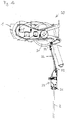
- a mobile harbor crane will be in Fig. 1 a shown.
- the crane has a load capacity of up to 140 t and a rope length of up to 80 m. It comprises a boom 1, which can be pivoted up and down about a horizontal axis, which is formed by the hinge axis 2, with which it is attached to a tower 3.
- the tower 3 can be rotated about a vertical axis, whereby the boom 3 is rotated with this.
- the tower 3 is attached to a mounted on wheels 7 undercarriage 6.
- the length of the rope 8 can be changed by winds.
- the load 10 may be received by a manipulator or spreader 20 which may be rotated by rotator means 15 mounted in a hook hanging on the rope 8.
- the load 10 is rotated either by rotating the tower and thereby the whole crane or by using the rotator means 15. In practice, both rotations must be used simultaneously to align the load in a desired position.
- control concept of the invention can be easily integrated into a control concept for the entire crane.
- the present invention discloses a determination method for improving these control and automation concepts of a mobile harbor crane, which in DE 10064182 . DE 10324692 and DE 10029579 as in O. Sawodny, H. Aschemann, J. kumpel, C. Tarin, K. Schneider, Anti-Sway Control for Boom Cares, American Control Conference, Anchorage USA, Proc. Pages 244-249, 2002 ; O.
- the present invention discloses a method of determining the moment of inertia of the load during crane operation based on data obtained by measuring the system. This type of estimation of the moment of inertia of the load with the aid of an observer approach leads to a better accuracy of the control method.
- Fig. 1b shows a gimbal element 35 which is attached to the boom head 30 of a boom 1 by gimbals 32 and 33 under the main role 31.
- the gimbal element 35 has rollers 36, by which it is guided on the rope 8, so that it follows the movements of the rope 8.
- the gimbals 32 and 33 allow the gimbal element 35 to freely move about a horizontal and a vertical axis, but prevent rotational movements. The movements of the gimbal and thus the movements of the rope can be measured.
- two gimbals 35 are provided, which are guided on the two cables to which the hook hangs.
- a gyroscope can be attached to the gimbals. If no gimbals are used, a gyroscope can also be attached directly to the hook or manipulator to determine its rotation angle.
- various observer methods for determining the moment of inertia of the load during crane operation can be used based on data obtained by measuring the system.
- the standard least squares method is unsatisfactory in estimating time-varying parameters.
- an exponential forgetting of the older data can be used.
- the so-called forgetting factor can be chosen such that the resulting gain matrix keeps a constant track. This approach can be further developed into the gain-fit forgetting method in which the forgetting factor is constantly changed according to the Gain Matrix norm.
- Another method for determining the parameters of dynamic systems is the extended Kalman filter used in the embodiment of the present invention. There are several advantages to using this technique, which will be discussed later.
- Fig. 2 shows a known adaptive control concept for managing the orientation of the load (of the container).
- This in O. Sawodny, A. Hildebrandt, K. Schneider, Control Design for the Crane Loads for Boom Cranes, International Conference on Robotics & Automation, Taipei Taiwan, Proc. Pages 2182-2187, 2003 ) and also in DE 10029579
- the disclosed control concept consists of a trajectory tracking control, an observer and a state feedback control to prevent torsional vibrations.
- the torsion angle is reconstructed from the angular velocity measured by a gyroscope in the hook.
- the angle between the hook and the container is measured by a transducer.
- the load orientation is obtained by summing both angles. Due to the fact that all parts of the control concept are model-based algorithms, they must be adapted to parameter changes. Most parameters can be measured directly, but the distribution of the load mass in the container and thus the moment of inertia of the container is unknown.
- the jib crane is equipped with a special manipulator, the so-called spreader.
- the manipulator can be rotated about the vertical axis by a rotator device containing a hydraulic drive. As in FIG. 4 is shown, this device is installed in the hook.
- the hook is attached to two ropes, where r and I s indicate the effective distance between the two parallel ropes or the rope length.
- the system consists of three extended bodies.
- the load (container), characterized by the moment of inertia J L , and the mass m L , the manipulator (container spreader) and the hook.
- J Sp and J H indicate the moment of inertia of the spreader and the hook, m Sp and m H respectively indicate the mass of the two bodies.
- the angle of rotation of the spreader with load is referred to as ⁇ L.
- the second angle ⁇ H indicates the torsion angle.
- the moment of inertia of the container during crane operation must be determined in order to adapt the model-based control concept. Due to this fact, the inertial moment determination algorithm must be iterative so that each time an accurate measurement of input / output data is obtained, a new parameter estimate is generated. In the past, a number of system determination methods were discussed. One of the methods for online parameter determination is the extended Kalman filter.
- a start pulse is generated at the moment a container is picked up.
- the states observed by the observer [ ⁇ H ⁇ H ] at this moment are the initial estimate x 0 for the filter algorithm.
- the output covariance matrix for the estimation error P 0 is used to tune the determination algorithm (see Section 4).
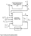
- the determination algorithm is implemented in a simulated environment. As in FIG. 5 is shown, the simulation model is terminated by the measurement signal ⁇ c_measured from the real system. Furthermore, a sequence of white noise is added to the output of the simulation model.
- the simulation results shown are obtained by using this configuration.
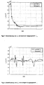
- the three curves represented the results obtained by using three different initial values for the covariance matrix of the estimation error. The higher the values of this matrix, the faster the estimated moment of inertia of the container reaches the reference value J Lmodel .
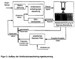
- the algorithm is implemented in the control and automation concept of the boom crane, in particular in the adaptive anti-torsional vibration control part, as in FIG. 3 is set out.
- the obtained experimental results are obtained online calculates the algorithm for the extended Kalman filter during crane operation.
- FIG. 7 shows, however, that the estimate of the moment of inertia of the load approaches the reference value of 36,000kgm 2 .
- the initial value for the moment of inertia ⁇ L0 was 47 . 000kgm 2 , and the remaining parameters and initial conditions were the same as the simulation configuration . Since the excitation of the torsional motion was stopped at 150 seconds, there is a residual deviation between the estimated J L and the reference value. Given the slow dynamic behavior of the flexible system, the estimated moment of inertia quickly approaches the values in the tolerance range around the reference value. A deviation of ⁇ 5% between ⁇ I and the reference value of the moment of inertia has no great effect on the performance of the anti-torsional vibration control.
- FIG. 8 shows the estimated moment of inertia of the load when the output value ⁇ L0 is equal to the reference value. In this case, the mass of the container is evenly distributed (see equation (24)).
- the obtained determination result of the parameter J L shows the robustness of the algorithm of the extended Kalman filter, since no estimates are calculated outside the tolerance range of ⁇ 5%.
- the small deviations between the estimated parameter and the reference value are caused by model uncertainties.
- the present invention discloses an extension of a control and automation concept for the orientation of a crane load. Because this concept is an adaptive model-based algorithm, the parameters of the dynamic model must be known as precisely as possible. Most parameters can be measured directly, but the moment of inertia of the crane load (container) must be determined based on the unknown distribution of mass during crane operation.
- the determination method used, the extended Kalman filter algorithm is derived from the dynamic model of the manipulator hanging from the cable. This parameter determination method is integrated into the anti-torsional vibration control and tested on a LIEBHERR LHM 402 mobile harbor crane. The obtained measurement results show the fast approach and the robustness of estimating the unknown moment of inertia of the crane load.
Landscapes
- Engineering & Computer Science (AREA)
- Mechanical Engineering (AREA)
- Control And Safety Of Cranes (AREA)
- Jib Cranes (AREA)
Description
Die vorliegende Erfindung betrifft ein Verfahren zum Steuern der Orientierung einer Kranlast, wobei ein Manipulator zum Handhaben der Last durch eine Rotatoreinrichtung mit einem an Seilen hängenden Haken verbunden ist und der Drehwinkel ϕ L der Last durch eine Steuereinrichtung unter Verwendung des Trägheitsmoments JL der Last als wichtigster Parameter gesteuert wird.The present invention relates to a method for controlling the orientation of a crane load, wherein a manipulator for handling the load by a rotator means is connected to a hook hanging on ropes and the angle of rotation φ L of the load by a control device using the moment of inertia J L of the load as most important parameter is controlled.
In
Für solche Steuersysteme ist ein Verfahren zum Steuern der Orientierung der Kranlast aus
Das bekannte Steuerverfahren nutzt ein dynamisches Modell des Systems basierend auf den Bewegungsgleichungen eines physikalischen Modells des Krans, wobei die bekannte Antitorsionsschwingungssteuerung aus einem Bahnplanungsmodul und einem Bahnnachverfolgungsmodul besteht. Das Bahnplanungsmodul berechnet die Bahn der Variablen, die den Zustand des Systems beschreiben, und erzeugt eine Referenzfunktion. Die Bahnnachverfolgungssteuerung kann in Störunterdrückung, Regelung mit Hilfsstellgröße (so genannte Feed Forward Control) und Regelung mit Zustandsrückführung (so genannte State Feed back Control) unterteilt werden. Die von der Regeleinrichtung verwendeten Parameter sind die Masse der Last und vor allem das Trägheitsmoment der Last.The known control method uses a dynamic model of the system based on the equations of motion of a physical model of the crane, the known anti-torsional vibration control consisting of a path planning module and a trajectory tracking module. The path planning module calculates the path of the variables describing the state of the system and generates a reference function. Trajectory tracking control can be subdivided into noise suppression, feedforward control, and state feedback control. The parameters used by the controller are the mass of the load and, above all, the moment of inertia of the load.
Die Massenverteilung in der Last, z.B. einem Container, ist aber nicht bekannt, und daher ist das Trägheitsmoment der Last ebenfalls nicht bekannt. Daher muss das Trägheitsmoment JL der Last geschätzt werden. Bei dem bekannten Steuersystem erfolgt dies durch Annehmen einer homogenen Massenverteilung in der Last und Berechnen eines geschätzten Trägheitsmoments JL der Last allein aus der Masse des Containers und den bekannten Maßen des Containers.However, the mass distribution in the load, eg a container, is not known, and therefore the moment of inertia of the load is also unknown. Therefore, the moment of inertia J L of the load must be estimated. In the known control system, this is done by assuming a homogeneous mass distribution in the load and calculating an estimated moment of inertia J L of the load solely from the mass of the container and the known dimensions of the container.
Die Lastverteilung in einem Container ist aber meist alles andere als homogen, so dass der geschätzte Wert der Last JL nur eine sehr ungenaue Annäherung ist. Da die Steuereinrichtung das Trägheitsmoment JL der Last als Parameter zum Steuern der Orientierung der Kranlast verwendet, führt die Differenz zwischen dem wahren Wert des Trägheitsmoments JL und der groben Schätzung zu einer Ungenauigkeit bei der Steuerung der Orientierung der Last.However, the load distribution in a container is usually anything but homogeneous, so that the estimated value of the load J L is only a very inaccurate approximation. Since the controller uses the moment of inertia J L of the load as a parameter for controlling the orientation of the crane load, the difference between the true one Value of the moment of inertia J L and the rough estimate of inaccuracy in controlling the orientation of the load.
Aus der
Das Ziel der vorliegenden Erfindung besteht daher darin, ein Verfahren zum Steuern der Orientierung der Kranlast an die Hand zu geben, das eine bessere Genauigkeit aufweist.The object of the present invention is therefore to provide a method for controlling the orientation of the crane load, which has a better accuracy.
Dieses Ziel wird durch ein Verfahren zum Steuerung der Orientierung einer Kranlast nach Anspruch 1 verwirklicht, wobei die Steuereinrichtung zum Steuern des Drehwinkels ϕ L der Last eine adaptive Steuereinrichtung ist, wobei das Trägheitsmoment JL der Last während des Kranbetriebs anhand von Daten ermittelt wird, die durch Messen des Systemzustands erhalten werden.This object is realized by a method of controlling the orientation of a crane load according to
Dadurch kann das Trägheitsmoment JL der Last ermittelt werden, was zu einer besseren Genauigkeit bei diesem wichtigen Parameter führt, der von der Steuereinrichtung zum Steuern der Orientierung der Kranlast genutzt wird. Die Steuereinrichtung wird während des Kranbetriebs durch Verwenden eines korrigierten Werts des Trägheitsmoments JL , der während des Kranbetriebs anhand der durch Messen des Systemzustands erhaltenen Daten bestimmt wird, als Parameter angepasst. Daher verwendet die Steuereinrichtung keinen einmalig geschätzten Festwert, sondern einen Wert, der mit Hilfe weiterer während des Kranbetriebs gewonnener Informationen angepasst wird.Thereby, the moment of inertia J L of the load can be determined, which leads to a better accuracy in this important parameter, which is used by the control device for controlling the orientation of the crane load. The controller is adjusted during crane operation by using a corrected value of the moment of inertia J L determined during crane operation from the data obtained by measuring the system state as a parameter. Therefore, the controller does not use a once-estimated fixed value, but a value that is adjusted with the help of further information obtained during crane operation.
Bei dem erfindungsgemäßen Verfahren zum Steuern der Drehung des Krans wird der Drehwinkel ϕ L der Last vorteilhafterweise mit Hilfe einer adaptiven Bahnnachverfolgungssteuerung gesteuert. Dies erlaubt eine wirksame Steuerung der Bewegungen der Kranlast. Zum Beispiel kann eine Regelung mit Hilfsstellgröße zum Berechnen der Bahnen der Systemvariablen anhand von Vorwärtsintegration der Bewegungsgleichungen des Systems verwendet werden, und eine Regelung mit Zustandsrückführung kann durch Messen des Systemzustands erhaltene Daten verwenden.In the method according to the invention for controlling the rotation of the crane, the angle of rotation φ L of the load is advantageously controlled by means of an adaptive trajectory tracking control. This allows effective control of the movements of the crane load. For example, an auxiliary control law may be used to calculate the orbits of the system variables based on forward integration of the equations of motion of the system, and a state feedback control may use data obtained by measuring the system state.
Bei dem erfindungsgemäßen Verfahren zum Steuern der Drehung einer Kranlast wird vorteilhafterweise ein dynamisches Modell des Systems zum Berechnen von Daten verwendet, die den Systemzustand beschreiben, d.h. der Bahnen der Systemvariablen. Diese Daten können dann die Grundlage zum Steuern der Drehung der Kranlast bilden, wobei das dynamische Modell des Systems eine genaue Beschreibung des Systems und daher eine präzise Steuerung der Orientierung der Kranlast erlaubt.In the method according to the invention for controlling the rotation of a crane load, it is advantageous to use a dynamic model of the system for calculating data describing the system condition, i. the paths of the system variables. This data can then form the basis for controlling the rotation of the crane load, the dynamic model of the system allowing a precise description of the system and therefore precise control of the orientation of the crane load.
Bei einer Weiterentwicklung des erfindungsgemäßen Verfahrens zum Steuern der Orientierung einer Kranlast kann die Differenz ϕ C zwischen dem Drehwinkel ϕ L der Last und dem Drehwinkel ϕ H des Hakens durch die Rotatoreinrichtung verändert werden. Dies erfolgt vorteilhafterweise durch Verwenden eines Hydraulikmotors für die Rotatoreinrichtung, so dass durch die Rotatoreinrichtung Drehmoment angelegt werden kann. Das ermöglicht ein Drehen des Manipulators und dadurch der Last um eine vertikale Achse, wodurch eine Orientierung der Last in jeder erwünschten Richtung ermöglicht wird.In a further development of the method according to the invention for controlling the orientation of a crane load, the difference φ C between the angle of rotation φ L of the load and the angle of rotation φ H of the hook can be changed by the rotator device. This advantageously takes place by using a hydraulic motor for the rotator device, so that torque can be applied by the rotator device. This permits rotation of the manipulator and thereby the load about a vertical axis, thereby allowing orientation of the load in any desired direction.
Bei einer Weiterentwicklung des erfindungsgemäßen Verfahrens zum Steuern der Orientierung einer Kranlast werden Torsionsschwingungen durch eine Antitorsionsschwingungseinrichtung unter Verwendung der von dem dynamischen Modell errechneten Daten vermieden. Diese Antitorsionsschwingungseinrichtung nutzt die von dem dynamischen Modell errechneten Daten, um die Rotatoreinrichtung so zu steuern, dass Schwingungen der Last vermieden werden. Dadurch kann die Antitorsionsschwingungseinrichtung Steuersignale erzeugen, die von dem dynamischen Modell vorhergesagten möglichen Schwingungen der Last entgegenwirken. Wird ein Hydraulikmotor für den Rotator verwendet, kann die Antitorsionsschwingungseinrichtung Signale zum Betätigen des Hydraulikmotors erzeugen, wodurch ein durch den resultierenden Durchfluss erzeugtes Drehmoment angelegt wird.In a further development of the method according to the invention for controlling the orientation of a crane load, torsional vibrations are avoided by an anti-vibration device using the data calculated by the dynamic model. This anti-torsional vibration device uses the data calculated by the dynamic model to control the rotator device to avoid vibrations of the load. Thereby, the anti-torsional vibrator may generate control signals that counteract the possible predicted potential vibrations of the load from the dynamic model. When a hydraulic motor is used for the rotator, the anti-vibration device may generate signals for actuating the hydraulic motor, thereby applying a torque generated by the resulting flow.
Bei einer Weiterentwicklung des erfindungsgemäßen Verfahrens zum Steuern der Orientierung einer Kranlast wird die Differenz ϕ C zwischen dem Drehwinkel ϕ L der Last und dem Drehwinkel ϕ H des Hakens durch einen mit der Rotatoreinrichtung verbundenen Messwertgeber gemessen. Dieser Messwertgeber ermöglicht das exakte Messen der Differenz ϕ C und trägt dadurch dazu bei, die Orientierung der Last zu steuern.In a further development of the method according to the invention for controlling the orientation of a crane load, the difference φ C between the angle of rotation φ L of the load and the angle of rotation φ H of the hook by one with the rotator device measured transmitter. This transmitter allows the exact measurement of the difference φ C and thus helps to control the orientation of the load.
Bei einer Weiterentwicklung des erfindungsgemäßen Verfahrens zum Steuern der Orientierung einer Kranlast werden die Bewegungen eines durch das Seil geführten kardanischen Elements gemessen, um Daten zu erhalten, durch welche der Drehwinkel ϕ H des Hakens und/oder der Drehwinkel ϕ L der Last ermittelt werden können. Das kardanische Element ist bevorzugt durch eine kardanische Verbindung mit dem Auslegerkopf des Krans verbunden und folgt den Bewegungen des Seils, an dem es durch Rollen geführt ist. Durch Messen der Bewegungen des kardanischen Elements können die Bewegungen des Seils ermittelt werden. Da der Haken meist an mehreren Seilen hängt, werden bevorzugt mindestens zwei kardanische Elemente vorgesehen, um die Bewegungen von mindestens zwei dieser Seile zu ermitteln. Der Drehwinkel ϕ H des an den Seilen hängenden Haken und/oder der Drehwinkel ϕ L der Last können dann aus den durch Messen der Bewegungen der kardanischen Elemente erhaltenen Daten ermittelt werden.In a further development of the method according to the invention for controlling the orientation of a crane load, the movements of a cardan element guided through the cable are measured in order to obtain data by which the angle of rotation φ H of the hook and / or the angle of rotation φ L of the load can be determined. The cardanic element is preferably connected by gimbal connection to the jib head of the crane and follows the movements of the rope on which it is guided by rollers. By measuring the movements of the gimbal, the movements of the rope can be determined. Since the hook usually hangs on several ropes, preferably at least two gimbal elements are provided to determine the movements of at least two of these ropes. The angle of rotation φ H of the hook hanging on the ropes and / or the angle of rotation φ L of the load can then be determined from the data obtained by measuring the movements of the gimbals.
Bei dem erfindungsgemäßen Verfahren zum Steuern der Orientierung einer Kranlast wird ein Gyroskop verwendet, um Daten zu erhalten, durch welche der Drehwinkel ϕ H des Hakens und/oder der Drehwinkel ϕ L der Last ermittelt werden können. Die Verwendung eines Gyroskops ist eine besonders effektive Möglichkeit, diese Daten mit ausreichender Präzision zu erhalten. Das Gyroskop kann an verschiedenen Stellen am Kran angebracht werden. Wenn kardanische Elemente verwendet werden, kann das Gyroskop an den kardanischen Elementen angebracht werden, um deren Bewegungen zu messen, es ist aber auch möglich, das Gyroskop direkt am Haken oder am Manipulator anzubringen.In the method according to the invention for controlling the orientation of a crane load, a gyroscope is used to obtain data by which the angle of rotation φ H of the hook and / or the angle of rotation φ L of the load can be determined. The use of a gyroscope is a particularly effective way to obtain this data with sufficient precision. The gyroscope can be attached to different locations on the crane. If cardanic elements are used, the gyroscope can be attached to the gimbals to measure their movements, but it is also possible to attach the gyroscope directly to the hook or to the manipulator.
Bei einer Weiterentwicklung des erfindungsgemäßen Verfahrens zum Steuern der Orientierung einer Kranlast wird die Änderung ϕ̇ H des Drehwinkels ϕ H des Hakens und/oder die Änderung ϕ̇ H , des Drehwinkels ϕ L der Last durch ein Gyroskop gemessen. Das Gyroskop kann entweder am Haken oder am Manipulator angebracht werden, bevorzugt aber am Haken. Gyroskope können die Winkelgeschwindigkeiten ϕ̇ H und ϕ̇ I messen, was eine Ermittelung des Drehwinkels ϕ H des Hakens und von ϕ L ermöglicht. Wenn ϕ̇ H von dem Gyroskop gemessen wird, kann ϕ H durch Integration ermittelt werden. Der Drehwinkel ϕ L der Last kann dann durch Verwenden der Differenz ϕ C zwischen dem Drehwinkel ϕ L der Last und dem vom Messwertgeber gemessenen Drehwinkel ϕ H des Hakens berechnet werden. Da der von dem Gyroskop gemessene Wert von ϕ̇ H Rauschen und ein Offset enthält, würde eine direkte Integration zu einer Summierung dieser Fehler führen, was zu schlechten Ergebnissen bei der Genauigkeit führen würde. Daher wird vorteilhafterweise ein Störbeobachter zum Ausgleichen des Offset verwendet. Dies erlaubt eine stabilere Schätzung des Drehwinkels ϕ L aus der Winkelgeschwindigkeit ϕ̇ H .In a further development of the method according to the invention for controlling the orientation of a crane load, the change φ̇ H of the angle of rotation φ H of the hook and / or the change φ̇ H , of the angle of rotation φ L of the load is measured by a gyroscope. The gyroscope can be mounted either on the hook or on the manipulator be, but preferably on the hook. Gyroscopes can measure the angular velocities φ̇ H and φ̇ I , which enables a determination of the angle of rotation φ H of the hook and of φ L. If .phi H is measured by the gyroscope, φ H can be determined by integration. The rotational angle φ L of the load can then be calculated by using the difference φ C between the rotational angle φ L of the load and the rotational angle φ H of the hook measured by the transducer. Since the value of φ̇ H measured by the gyroscope contains noise and an offset, direct integration would result in summation of these errors, which would lead to poor accuracy results. Therefore, advantageously, an observer is used to compensate for the offset. This allows a more stable estimate of the rotation angle φ L from the angular velocity φ̇ H.
Bei einer Weiterentwicklung des erfindungsgemäßen Verfahrens zum Steuern der Orientierung einer Kranlast beruht das dynamische Modell des Systems auf den Bewegungsgleichungen eines physikalischen Modells mindestens der Seile, des Hakens und der Last. Bei einem solchen physikalischen Modell bilden der Haken und die Last, die an den Seilen hängen, ein Torsionspendel, dessen Bewegungsgleichungen mit Hilfe z.B. des Lagrange-Formalismus ermittelt werden können. Dies ermöglicht eine realistische Beschreibung des Systems und daher eine präzise Bahnplanung und -steuerung.In a further development of the method according to the invention for controlling the orientation of a crane load, the dynamic model of the system is based on the equations of motion of a physical model of at least the ropes, the hook and the load. In such a physical model, the hook and the load hanging on the ropes form a torsion pendulum whose equations of motion are determined by means of e.g. of the Lagrange formalism can be determined. This allows a realistic description of the system and therefore precise path planning and control.
Vorteilhafterweise werden das Trägheitsmoment JH des Hakens und JSp des Manipulators als Parameter für die Steuerung des Drehwinkels ϕ L der Last verwendet. Auch wenn das Trägheitsmoment JH des Hakens und JSp des Manipulators meist kleiner als das Trägheitselement JL der Last sind, tragen sie dennoch zum Drehverhalten des Systems bei und sollten bei den Berechnungen und dem physikalischen Modell berücksichtigt werden.Advantageously, the moment of inertia J H of the hook and J Sp of the manipulator are used as parameters for the control of the angle of rotation φ L of the load. Even though the moment of inertia J H of the hook and J Sp of the manipulator are usually smaller than the inertia element J L of the load, they nevertheless contribute to the rotational behavior of the system and should be taken into account in the calculations and the physical model.
Bei einer Weiterentwicklung des erfindungsgemäßen Verfahrens zum Steuern der Orientierung einer Kranlast wird während des Betriebs des Krans an der Last und/oder dem Haken ein Drehmoment angelegt. Die durch Messen des Systemzustands während des Anlegens eines Drehmoments am Haken und/oder der Last erhaltenen Daten erlauben die Schätzung des Trägheitsmoments JL der Last, z.B. durch Verwenden eines Beobachters.In a further development of the method according to the invention for controlling the orientation of a crane load, a torque is applied to the load and / or the hook during operation of the crane. By measuring the system condition while applying a torque to the hook and / or the load obtained data allow the estimation of the moment of inertia J L of the load, eg by using an observer.
Vorteilhafterweise umfassen die durch Messen des Systemzustands erhaltenen Daten mindestens die Änderung ϕ H des Drehwinkels ϕ H des Hakens und/oder die Änderung ϕ̇ I , des Drehwinkels ϕ L der Last als Reaktion auf das an der Last und/oder dem Haken angelegten Drehmoment. Diese Daten können dann zum Schätzen des Trägheitsmoments JL der Last verwendet werden, z.B. durch Vergleichen der von dem dynamischen Modell errechneten Daten mit den gemessenen Daten.Advantageously, the data obtained by measuring the system state comprises at least the change φ H of the angle of rotation φ H of the hook and / or the change φ̇ I , the angle of rotation φ L of the load in response to the torque applied to the load and / or the hook. This data can then be used to estimate the moment of inertia J L of the load, eg by comparing the data calculated from the dynamic model with the measured data.
Bei einer Weiterentwicklung des erfindungsgemäßen Verfahrens zum Steuern der Orientierung einer Kranlast wird ein Wert des Trägheitsmoments JL0 , der auf der Grundlage der Masse und der Maße der Last allein geschätzt wird, als Ausgangswert für JL verwendet, und korrigierte Werte JLk werden in einem iterativen Prozess ermittelt, um das Trägheitsmoment JL zu bestimmen. Dies ergibt anhand der Daten, die schnell verfügbar sind, eine grobe Schätzung des Ausgangswerts für JL" während bessere Schätzungen während des Kranbetriebs anhand der weiteren Daten ermittelt werden, die durch Messen des Systemzustands erhalten werden.In a further development of the method according to the invention for controlling the orientation of a crane load, a value of the moment of inertia J L0 , which is estimated on the basis of the mass and the dimensions of the load alone, is used as the output value for J L , and corrected values J Lk are in one iterative process is determined to determine the moment of inertia J L. This gives a rough estimate of the output value for J L "from the data that is readily available while better estimates are made during crane operation based on the additional data obtained by measuring the system condition.
Bei einer Weiterentwicklung des erfindungsgemäßen Verfahrens zum Steuern der Orientierung einer Kranlast werden während des Kranbetriebs den Systemzustand beschreibende Daten von dem dynamischen Modell basierend auf einem Wert JL,k-1 des Trägheitsmoments JL errechnet, und ein korrigierter Wert JLk des Trägheitsmoments JL wird anhand der errechneten Daten und der durch Messen des Systemzustands erhaltenen Daten ermittelt, um das Trägheitsmoment JL zu bestimmen. Dies erlaubt eine weitaus bessere Schätzung des Trägheitsmoments JL als die Verwendung der Masse und der Maße der Last allein.In a further development of the method according to the invention for controlling the orientation of a crane load during crane operation, data describing the system state are calculated from the dynamic model based on a value J L, k-1 of the moment of inertia J L , and a corrected value J Lk of the moment of inertia J L is determined from the calculated data and the data obtained by measuring the system state to determine the moment of inertia J L. This allows a much better estimate of the moment of inertia J L than the use of mass and the dimensions of the load alone.
Das Trägheitsmoment JL wird erfindungsgemäß mit Hilfe eines Beobachters bestimmt. Dieses Verfahren zur Schätzung des Trägheitsmoments JL nutzt durch das dynamische Modell errechnete Daten und kombiniert diese mit Daten, die durch Messen des Systemzustands erhalten wurden, um den Parameter JL des dynamischen Modells zu schätzen. Das Verwenden eines Beobachters zum Ermitteln von Variablen des Systems wie zum Beispiel des Drehwinkels ϕ H des Hakens aus der von dem Gyroskop gemessenen Winkelgeschwindigkeit ϕ̇ H war bereits bekannt. Hier wird aber ein Parameter des Modells mit Hilfe eines Beobachters ermittelt, was zu einer adaptiven Steuerung führt.The moment of inertia J L is determined according to the invention with the help of an observer. This method of estimating the moment of inertia J L uses data computed by the dynamic model and combines it with data, obtained by measuring the system state to estimate the parameter J L of the dynamic model. The use of an observer to determine variables of the system, such as the angle of rotation φ H of the hook from the angular velocity φ H measured by the gyroscope, was already known. Here, however, a parameter of the model is determined with the aid of an observer, which leads to an adaptive control.
Wenn ein Parameter des Modells von dem Beobachter geschätzt wird, wird das Problem nichtlinear, so dass das Trägheitsmoment JL vorteilhafterweise mit Hilfe eines nichtlinearen Beobachters bestimmt wird. Es gibt verschiedene Möglichkeiten zum Implementieren eines nichtlinearen Beobachters, insbesondere bei zeitvarianten Modellen, zum Beispiel einen High-Gain-Ansatz oder das erweiterte Kalman-Filter.When a parameter of the model is estimated by the observer, the problem becomes non-linear, so that the moment of inertia J L is advantageously determined by means of a non-linear observer. There are various ways to implement a nonlinear observer, especially in time-variant models, for example a high-gain approach or the extended Kalman filter.
Die letzte Möglichkeit bietet ein sehr stabiles System zum schnellen Schätzen von Parametern des Systems, so dass das Trägheitsmoment JL vorteilhafterweise mit Hilfe eines erweiterten Kalman-Filters bestimmt werden kann.The last possibility offers a very stable system for rapidly estimating parameters of the system, so that the moment of inertia J L can advantageously be determined with the aid of an extended Kalman filter.
Bei einer Weiterentwicklung des erfindungsgemäßen Verfahrens zum Steuern der Orientierung einer Kranlast wird für die Schätzung eines Ausgangswerts JL0 des Trägheitsmoments JL der Last eine homogene Verteilung von Masse in der Last angenommen. Dies erlaubt eine schnelle Berechnung, die nur die Masse und die Maße der Last als Eingabe benötigt.In a further development of the method according to the invention for controlling the orientation of a crane load, a homogeneous distribution of mass in the load is assumed for the estimation of an output value J L0 of the moment of inertia J L of the load. This allows a quick calculation that requires only the mass and dimensions of the load as input.
Bei einer Weiterentwicklung des erfindungsgemäßen Verfahrens zum Steuern der Orientierung einer Kranlast wird Rauschen in den durch Messungen erhaltenen Daten bei der Bestimmung des Trägheitsmoments JL berücksichtigt. Dies führt zu mehr Präzision bei der Schätzung des Trägheitsmoments JL, die auf den gemessenen Daten beruht und daher durch Rauschen in den Messungen beeinflusst wird.In a further development of the method according to the invention for controlling the orientation of a crane load, noise in the data obtained by measurements is taken into account in the determination of the moment of inertia J L. This leads to more precision in the estimation of the moment of inertia J L , which is based on the measured data and therefore influenced by noise in the measurements.
Vorteilhafterweise wird das Rauschen in den durch Messungen erhaltenen Daten durch Kovarianzmatrizen modelliert. Dies erlaubt eine quantitative Beschreibung des Einflusses des Rauschens und kann die sich aus dem Rauschen ergebenden Fehler minimieren.Advantageously, the noise in the data obtained by measurements is modeled by covariance matrices. This allows a quantitative description influence of noise and can minimize the errors resulting from noise.
Diese Kovarianzmatrizen werden vorteilhafterweise experimentell ermittelt. Durch Testen des Steuersystems mit verschiedenen Werten für die Kovarianzmatrizen können die besten Werte für eine schnelle und stabile Schätzung des Trägheitsmoments JL ermittelt und für den Beobachter verwendet werden.These covariance matrices are advantageously determined experimentally. By testing the control system with different values for the covariance matrices, the best values for a fast and stable estimation of the moment of inertia J L can be determined and used for the observer.
Die vorliegende Erfindung umfasst weiterhin ein System zum Steuern der Orientierung einer Kranlast mit Hilfe eines der oben beschriebenen Verfahren. Ein solches Steuersystem umfasst eine Steuereinrichtung zum Steuern des Drehwinkels ϕ L der Last. Die Steuereinrichtung enthält eine Bahnplanungseinrichtung und eine Bahnsteuerungseinrichtung sowie einen Beobachter zum Schätzen des Trägheitsmoments JL. The present invention further includes a system for controlling the orientation of a crane load using one of the methods described above. Such a control system comprises a control device for controlling the rotation angle φ L of the load. The control device includes a web planning device and a web control device and an observer for estimating the moment of inertia J L.
Die vorliegende Erfindung umfasst weiterhin einen Kran, insbesondere einen Auslegerkran, der ein System zum Steuern der Drehung einer Kranlast mit Hilfe eines der vorstehend beschriebenen Verfahren umfasst. Ein solcher Kran umfasst einen an Seilen hängenden Haken, eine Rotatoreinrichtung und einen Manipulator. Vorteilhafterweise umfasst der Kran auch ein Anti-Pendel-Steuersystem, das mit dem System zum Steuern der Drehung eines Krans zusammenwirkt. Wenn der Kran ein Auslegerkran ist, umfasst er einen Ausleger, der um eine horizontale Achse auf und ab geschwenkt und durch einen Turm um eine vertikale Achse gedreht werden kann. Ferner kann die Länge des Seils verändert werden.The present invention further comprises a crane, in particular a jib crane, comprising a system for controlling the rotation of a crane load by means of one of the methods described above. Such a crane comprises a hook-hanging hook, a rotator device and a manipulator. Advantageously, the crane also includes an anti-sway control system which cooperates with the system for controlling the rotation of a crane. When the crane is a jib crane, it comprises a boom that can be swung up and down about a horizontal axis and rotated by a tower about a vertical axis. Furthermore, the length of the rope can be changed.
Nun wird die vorliegende Erfindung anhand der folgenden Zeichnungen näher beschrieben. Darin zeigen
- Fig. 1a
- eine Seitenansicht und eine Draufsicht eines Hafenmobilkrans,
- Fig. 1b
- eine Seitenansicht eines Auslegerkopfes des Hafenmobilkrans mit einem kardanischen Element,
- Fig. 2
- den Steueraufbau des Hafenmobilkrans,
- Fig. 3
- den Aufbau der Antitorsionsschwingungssteuerung,
- Fig. 4
- eine an einem Seil hängende Rotatoreinrichtung mit Manipulator und Last,
- Fig. 5
- den Aufbau eines Simulationsumfelds,
- Fig. 6
- die Ermittlungsleistung des erweiterten Kalman-Filters abhängig von der Wahrscheinlichkeitsmatrix P0,
- Fig. 7
- die Bestimmung von JL mit falschem Ausgangswert,
- Fig. 8
- die Bestimmung von JL mit richtigem Ausgangswert.
- Fig. 1a
- a side view and a top view of a mobile harbor crane,
- Fig. 1b
- a side view of a jib head of the mobile harbor crane with a gimbal element,
- Fig. 2
- the control structure of the mobile harbor crane,
- Fig. 3
- the structure of the anti-torsional vibration control,
- Fig. 4
- a rotator device with manipulator and load hanging from a cable,
- Fig. 5
- the construction of a simulation environment,
- Fig. 6
- the determination performance of the extended Kalman filter as a function of the probability matrix P 0 ,
- Fig. 7
- the determination of J L with the wrong initial value,
- Fig. 8
- the determination of J L with the correct initial value.
Auslegerkrane werden häufig zum Abwickeln von Frachtumschlagvorgängen in Häfen eingesetzt. Ein solcher Hafenmobilkran wird in
Der Einfachheit halber wird hier nur die Drehung einer Last, die an einem ansonsten unbeweglichen Kran hängt, erläutert. Das erfindungsgemäße Steuerkonzept kann aber problemlos in ein Steuerkonzept für den gesamten Kran integriert werden.For the sake of simplicity, only the rotation of a load which hangs on an otherwise immovable crane will be explained here. However, the control concept of the invention can be easily integrated into a control concept for the entire crane.
Insbesondere für Containerumschlag wurde die aus
Da das Spreader/Rotator-System als Roboter mit flexiblem Arm mit einem langsamen dynamischen Verhalten betrachtet werden kann, wird ein adaptives und modellbasiertes Verfahren zur Steuerung des Manipulators eingesetzt. Um die Leistung dieses Steuerkonzepts zu verbessern, müssen die Parameter des dynamischen Modells des Systems und insbesondere das Trägheitsmoment der Last so genau wie möglich bekannt sein. Die vorliegende Erfindung offenbart ein Bestimmungsverfahren zum Verbessern dieser Steuer- und Automatisierungskonzepte eines Hafenmobilkrans, die in
Aufgrund der ungewöhnlich inhomogenen Verteilung der Last in dem Container ist das anhand der Annahme, dass die Verteilung von Last homogen ist, geschätzte Trägheitsmoment nur eine sehr grobe Annäherung an diesen Parameter, was zu einer ungenauen Steuerung der Orientierung des Containers führt. Daher offenbart die vorliegende Erfindung ein Verfahren zum Bestimmen des Trägheitsmoments der Last während des Kranbetriebs beruhend auf durch Messen des Systems erhaltenen Daten. Diese Art des Schätzens des Trägheitsmoments der Last mit Hilfe eines Beobachteransatzes führt zu einer besseren Genauigkeit des Steuerverfahrens.Due to the unusually inhomogeneous distribution of the load in the container, the estimated moment of inertia based on the assumption that the distribution of load is homogeneous is only a very rough approximation to this parameter, resulting in an inaccurate control of the orientation of the container. Therefore, the present invention discloses a method of determining the moment of inertia of the load during crane operation based on data obtained by measuring the system. This type of estimation of the moment of inertia of the load with the aid of an observer approach leads to a better accuracy of the control method.
Die Daten, auf denen die Ermittlung des Trägheitsmoments der Last beruht, können durch verschiedene Verfahren erhalten werden.
In der vorliegenden Erfindung können verschiedene Beobachterverfahren zum Bestimmen des Trägheitsmoments der Last während des Kranbetriebs anhand von durch Messen des Systems erhaltenen Daten verwendet werden.In the present invention, various observer methods for determining the moment of inertia of the load during crane operation can be used based on data obtained by measuring the system.
Durch Anwenden der Methode der kleinsten Quadrate bei den gemessenen Eingabe-/Ausgabedaten können Systemparameter geschätzt werden. Die Standardmethode der kleinsten Quadrate ist aber beim Schätzen von sich zeitlich ändernden Parametern unbefriedigend. Zur Lösung dieses Problems kann ein exponentielles Vergessen der älteren Daten verwendet werden. Der so genannte Forgetting Faktor kann so gewählt werden, dass die resultierende Gain-Matrix eine konstante Spur hält. Dieser Ansatz kann weiter zu dem Gain-angepassen Verfahren des Vergessens entwickelt werden, bei dem der Forgetting-Faktor entsprechend der Norm der Gain-Matrix ständig verändert wird.By applying the least squares method to the measured input / output data, system parameters can be estimated. However, the standard least squares method is unsatisfactory in estimating time-varying parameters. To solve this problem, an exponential forgetting of the older data can be used. The so-called forgetting factor can be chosen such that the resulting gain matrix keeps a constant track. This approach can be further developed into the gain-fit forgetting method in which the forgetting factor is constantly changed according to the Gain Matrix norm.
Ein anderes Verfahren zur Bestimmung der Parameter von dynamischen Systemen ist das erweiterte Kalman-Filter, das in der erfindungsgemäßen Ausführung verwendet wird. Bei der Verwendung dieses Verfahrens gibt es mehrere Vorteile, auf die später eingegangen wird.Another method for determining the parameters of dynamic systems is the extended Kalman filter used in the embodiment of the present invention. There are several advantages to using this technique, which will be discussed later.
Da dieser Parameter einen großen Einfluss auf das dynamische Verhalten des Torsionsoszillators und somit auf die Leistung der Antischwingungssteuerung hat, muss er on-line bestimmt werden.Since this parameter has a great influence on the dynamic behavior of the torsional oscillator and thus on the performance of the anti-vibration control, it must be determined on-line.
Zum Umschlagen der Container ist der Auslegerkran mit einem speziellen Manipulator, dem so genannten Spreader, ausgerüstet. Der Manipulator kann durch eine einen Hydraulikantrieb enthaltende Rotatoreinrichtung um die vertikale Achse gedreht werden. Wie in
Der Haken ist an zwei Seilen befestigt, wobei r und Is den effektive Abstand der beiden parallelen Seile bzw. die Seillänge angeben. Das System besteht aus drei erweiterten Körpern. Der Last (Container), gekennzeichnet durch das Trägheitsmoment JL, und der Masse mL, dem Manipulator (Container-Spreader) und dem Haken. JSp und JH geben das Trägheitsmoment des Spreader und des Hakens an, mSp und mH geben jeweils die Masse der beiden Körper an. Der Drehwinkel des Spreader mit Last wird als ϕ L bezeichnet. Der zweite Winkel ϕ H gibt den Torsionswinkel an.The hook is attached to two ropes, where r and I s indicate the effective distance between the two parallel ropes or the rope length. The system consists of three extended bodies. The load (container), characterized by the moment of inertia J L , and the mass m L , the manipulator (container spreader) and the hook. J Sp and J H indicate the moment of inertia of the spreader and the hook, m Sp and m H respectively indicate the mass of the two bodies. The angle of rotation of the spreader with load is referred to as φ L. The second angle φ H indicates the torsion angle.
Zum Ableiten der Bewegungsgleichungen des betrachteten mechanischen Systems wird die Lagrange-Formulierung verwendet (nach ![]()
![]()
Die Lagrange-Funktion L ist als Differenz zwischen der kinetischen Energie T und der potentiellen Energie U des Systems definiert. ![]()
![]()
Unter der Annahme, dass Haken, Spreader und Last (Container) zu einem erweiterten Körper mit dem Gesamtträgheitsmoment Jtotal = JH + JSp + JL zusammengefasst werden, werden die kinetische und potentielle Energie wie folgt erhalten: 
cT beschreibt die linearisierte Torsionssteifheit der beiden parallelen Seile als Funktion der Parameter Mtotal = mH + mSp + mL und Is , (- ist die Gravitationskonstante): 
Das Lösen der Gleichung (1) mit der resultierenden Lagrange-Funktion und der generalisierten Koordinate q = ϕ H führt zu dem dynamischen Modell der Rotatoreinrichtung mit Last. ![]()
![]()
Die generalisierte Kraft ist das Moment des Hydraulikmotors und kann definiert werden als ![]()
![]()
![]()
![]()
Für das Bestimmungsverfahren wird das stetige Modell (Gleichungen (5) und (6)) in ein Raummodell diskreten Zustands mit folgender Form umgewandelt: 
Die Systemmatrizen, der Zustandsvektor und der Eingabevektor werden erhalten: 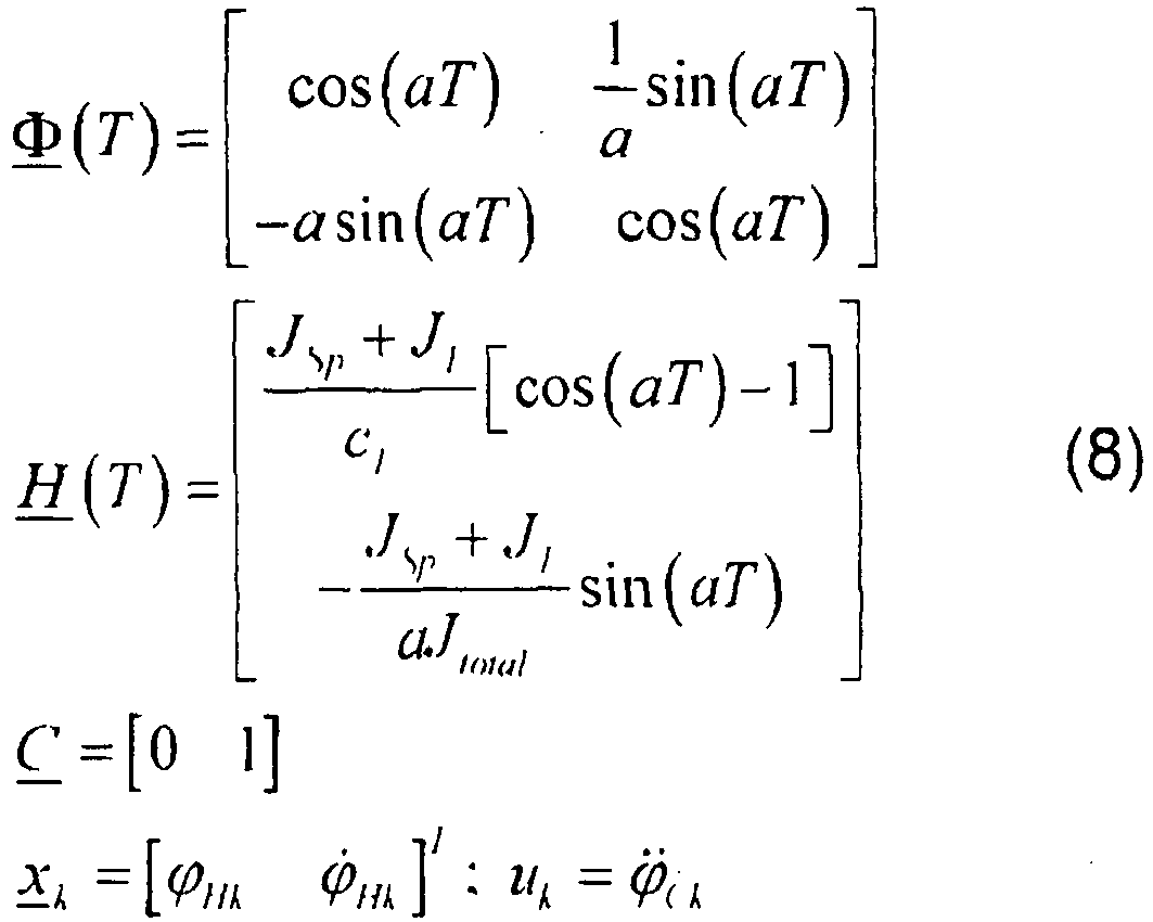

Für den vorgegebenen Anwendungsfall muss das Trägheitsmoment des Containers während des Kranbetriebs ermittelt werden, um das modellbasierte Steuerkonzept anzupassen. Aufgrund dieser Tatsache muss der Bestimmungsalgorithmus für das Trägheitsmoment iterativ sein, so dass jedes Mal, da eine exakte Messung von Eingabe-/Ausgabedaten erhalten wird, eine neue Parameterschätzung erzeugt wird. In der Vergangenheit wurden etliche Systembestimmungsverfahren diskutiert. Eines der Verfahren für die Online-Parameterbestimmung ist das erweiterte Kalman-Filter.For the given application, the moment of inertia of the container during crane operation must be determined in order to adapt the model-based control concept. Due to this fact, the inertial moment determination algorithm must be iterative so that each time an accurate measurement of input / output data is obtained, a new parameter estimate is generated. In the past, a number of system determination methods were discussed. One of the methods for online parameter determination is the extended Kalman filter.
Zum Schätzen des unbekannten Trägheitsmoments des Containers wird der Zustandsvektor x k des diskreten Zustandsraummodells (Gleichungen (7) und (8)) um den unbekannten Parameter JL erweitert (![]()
![]()
Mit dieser Erweiterung ergibt sich ein nichtlineares diskretes Modell folgender Form: ![]()
![]()
![]()
![]()
Die vektorbewerteten Funktionen f und g werden erhalten durch: 
Wie in Abschnitt 1 erläutert kann der Drehwinkel des Haken ϕ H nicht direkt gemessen werden. Er muss aus der Winkelgeschwindigkeit ϕ̇ Hgyro rekonstruiert werden, die durch ein Gyroskop im Haken gemessen wird. Da das Gyroskopsignal gestört ist, muss das Messrauschen berücksichtigt werden, was zu einer Systemausgabe führt, die modelliert werden kann als: ![]()
![]()
![]()
![]()
![]()
![]()
Um das Kalman-Filter an dem erhaltenen nichtlinearen System anzulegen, muss es mit Hilfe einer linearen Taylor-Annäherung an die Schätzung des vorherigen Zustands x k : linearisiert werden: 

Durch Berechnen der Koeffizienten für i, j = 1,...,3 wird die Jacobische Matrix erhalten als: 
Mit dem linearisierten Modell und den Kovarianzmatrizen Q und R kann der optimale Kalman-Filter-Algorithmus in folgender Form abgeleitet werden (
- 1. Schritt: Die Vorhersage der Zustände [ϕ Hk ϕ̇ Hk ] und des Parameters JLk wird aus der Eingabe uk und den geschätzten nicht gestörten Zuständen xk berechnet.

- 2. Schritt: Die Kovarianzmatrizen des Vorhersagefehlers M k+1 und der Schätzungsfehler P k+1 sowie die Kalman-Gain-Matrix K k+1 werden mit Hilfe von Folgendem berechnet (I ist die Identitätsmatrix):


- 3. Schritt: Die Schätzung des Zustandsvektors und des Trägheitsmoments des Containers werden durch Korrigieren der vorhergesagten Werte mit der gewichteten Differenz zwischen der gemessenen und der vorhergesagten Winkelgeschwindigkeit des Hakens erhalten.

- 1st step: The prediction of the states [φ Hk φ̇ Hk ] and the parameter J Lk is calculated from the input u k and the estimated undisturbed states x k .
- 2nd step: The covariance matrices of the prediction error M k + 1 and the estimation error P k + 1 and the Kalman gain matrix K k + 1 are calculated using (I is the identity matrix):
- 3rd step: The estimation of the state vector and the moment of inertia of the container are obtained by correcting the predicted values with the weighted difference between the measured and the predicted angular velocity of the hook.
Der beschriebene Algorithmus wird jedes Mal, wenn eine neue Messung von Eingabe-/Ausgabedaten verfügbar ist (k = 1,2,...), ausgeführt. Zum Initialisieren des erweiterten Kalman-Filters wird in dem Moment, da ein Container aufgenommen wird, ein Startimpuls erzeugt. Die von dem Störbeobachter beobachteten Zustände [ϕ H ϕ̇ H ] sind in diesem Moment die Anfangsschätzung x̂ 0 für den Filteralgorithmus. Der Ausgangswert für das Trägheitsmoment des Containers ĴL0 kann durch Annehmen, dass der Container eine gleichmäßig verteilte Masse hat, erhalten werden. Da die Länge Icontainer und die Masse mL des Containers gemessen werden können und die Breite konstant ist (bcontainer = 2,4m), kann das Trägheitsmoment wie folgt berechnet werden: ![]()
![]()
Die Ausgangskovarianzmatrix für den Schätzungsfehler P 0 wird zum Abstimmen des Bestimmungsalgorithmus verwendet (siehe Abschnitt 4).The output covariance matrix for the estimation error P 0 is used to tune the determination algorithm (see Section 4).
Um gute Elemente der Kovarianzmatrix für den Schätzungsfehler P 0 zu finden, wird der Bestimmungsalgorithmus in einem simulierten Umfeld implementiert. Wie in
Die Parameter und die Ausgangsbedingungen der Simulation sind wie folgt: 
Die in
Die Ergebnisse zeigen, dass selbst bei Simulation ein oberer Grenzwert für den Ausgangswert der Kovarianzmatrix des Schätzungsfehlers vorliegt, wenn das Simulationsmodell durch das Messsignal ϕ̈ c_measured beendet wird. Dies bedeutet, dass der Bestimmungsalgorithmus stark auf nicht berücksichtigte Störungen der Systemeingabe anspricht, wenn die Ausgangskovarianzmatrix P 0ij =2·1010δ ij ; i,j =1,2,3 (δ ij ist das Kronecker-Delta) oder größer ist.The results show that even with simulation there is an upper limit for the output value of the covariance matrix of the estimation error when the simulation model is terminated by the measurement signal φ̈ c_measured . This means that the determination algorithm responds strongly to disregarded system input perturbations when the output covariance matrix P 0 ij = 2 * 10 10 δ ij ; i, j = 1,2,3 (δ ij is the Kronecker delta) or greater.
Um die Leistung des erweiterten Kalman-Filters zu beurteilen, wird der Algorithmus in dem Steuer- und Automatisierungskonzept des Auslegerkrans, insbesondere in dem adaptiven Antitorsionsschwingungssteuerteil, implementiert, wie in
Der Ausgangswert für das Trägheitsmoment ĴL0 wurde mit 47.000kgm2 gewählt, und die verbleibenden Parameter und Ausgangsbedingungen waren gleich der Simulationskonfiguration. Da die Erregung der Torsionsbewegung bei 150 Sekunden angehalten wurde, besteht zwischen dem geschätzten JL und dem Bezugswert eine Restabweichung. Unter Berücksichtigung des langsamen dynamischen Verhaltens des flexiblen Systems nähert sich das geschätzte Trägheitsmoment schnell den Werten in dem Toleranzbereich um den Bezugswert. Eine Abweichung von ±5% zwischen ĴI und dem Bezugswert des Trägheitsmoments hat keine große Wirkung auf die Leistung der Antitorsionsschwingungssteuerung.
Das erhaltene Bestimmungsergebnis des Parameters JL zeigt die Robustheit des Algorithmus des erweiterten Kalman-Filters, da außerhalb des Toleranzbereichs von ±5% keine Schätzungen berechnet werden. Die kleinen Abweichungen zwischen dem geschätzten Parameter und dem Bezugswert sind durch Modellunsicherheiten verursacht.The obtained determination result of the parameter J L shows the robustness of the algorithm of the extended Kalman filter, since no estimates are calculated outside the tolerance range of ± 5%. The small deviations between the estimated parameter and the reference value are caused by model uncertainties.
Die vorliegende Erfindung offenbart eine Ausweitung eines Steuer- und Automatisierungskonzepts für die Orientierung einer Kranlast. Da dieses Konzept ein adaptiver modellbasierender Algorithmus ist, müssen die Parameter des dynamischen Modells so präzis wie möglich bekannt sein. Die meisten Parameter können direkt gemessen werden, aber das Trägheitsmoment der Kranlast (Container) muss aufgrund der unbekannten Verteilung der Masse während des Kranbetriebs bestimmt werden. Das verwendete Bestimmungsverfahren, der erweiterte Kalman-Filter-Algorithmus, wird anhand des dynamischen Modells des an dem Seil hängenden Manipulators abgeleitet. Dieses Parameterbestimmungsverfahren wird in die Antitorsionsschwingungssteuerung integriert und wurde an einem LIEBHERR LHM 402 Hafenmobilkran gestestet. Die erhaltenen Messergebnisse zeigen die schnelle Annäherung und die Robustheit der Schätzung des unbekannten Trägheitsmoments der Kranlast.The present invention discloses an extension of a control and automation concept for the orientation of a crane load. Because this concept is an adaptive model-based algorithm, the parameters of the dynamic model must be known as precisely as possible. Most parameters can be measured directly, but the moment of inertia of the crane load (container) must be determined based on the unknown distribution of mass during crane operation. The determination method used, the extended Kalman filter algorithm, is derived from the dynamic model of the manipulator hanging from the cable. This parameter determination method is integrated into the anti-torsional vibration control and tested on a LIEBHERR LHM 402 mobile harbor crane. The obtained measurement results show the fast approach and the robustness of estimating the unknown moment of inertia of the crane load.
Claims (22)
- A method for controlling the orientation of a crane load, wherein a manipulator for manipulating the load is connected by a rotator unit to a hook suspended on ropes and the rotational angle ϕ L of the load is controlled by a control unit using the moment of inertia JL of the load as most important parameter, wherein the control unit is an adaptive control unit, wherein the moment of inertia JL of the load is identified during operation of the crane based on at least one of the following variables obtained by measuring the state of the system: rotational angle ϕ H of the hook, rotational angle ϕ L of the load, change ϕ̇ H in the rotational angle ϕ H of the hook and/or change ϕ̇ I in the rotational angle ϕL of the load,
characterized in that,
a gyroscope is used to obtain data by which the rotational angle ϕH of the hook and/or the rotational angle ϕ L of the load can be determined, wherein the moment of inertia JL is identified using an observer. - The method for controlling the orientation of a crane load according to claim 1, wherein the rotational angle ϕ L of the load is controlled using an adaptive trajectory tracking control.
- The method for controlling the orientation of a crane load according to claim 1, wherein a dynamic model of the system is used to calculate data describing the state of the system.
- The method for controlling the orientation of a crane load according to claim 3, wherein torsional oscillations are avoided by a anti-torsional oscillation unit using the data calculated by the dynamical model.
- The method for controlling the orientation of a crane load according to claim 1, wherein the difference ϕ C between the rotational angle ϕ L of the load and the rotational angle ϕ H of the hook can be varied by the rotator unit.
- The method for controlling the orientation of a crane load according to claim 1, wherein the difference ϕ C between the rotational angle ϕ L of the load and the rotational angle ϕ H of the hook is measured by an encoder connected to the rotator unit.
- The method for controlling the orientation of a crane load according to claim 1, wherein the movements of a cardanic element guided by the rope are measured to obtain data by which the rotational angle ϕ H of the hook and/or the rotational angle ϕ L of the load can be determined.
- The method for controlling the orientation of a crane load according to claim 1, wherein the change ϕ̇ H in the rotational angle ϕ H of the hook and/or the change ϕ̇ I in the rotational angle ϕ L of the load are measured by a gyroscope.
- The method for controlling the orientation of a crane load according to claim 3, wherein the dynamical model of the system is based on the equations of motion of a physical model of at least the ropes, the hook and the load.
- The method for controlling the orientation of a crane load according to claim 1 or 3, wherein the moment of inertia JH of the hook and JSp of the manipulator are used as parameters.
- The method for controlling the orientation of a crane load according to claim 1, wherein during the operation of the crane a torque is applied to the load and/or the hook.
- The method for controlling the orientation of a crane load according to claim 11, wherein the data obtained by measuring the state of the system at least comprise the change ϕ̇ H in the rotational angle ϕ H of the hook and/or the change ϕ̇ I in the rotational angle ϕ L of the load in reaction to the torque applied to the load and/or the hook.
- The method for controlling the orientation of a crane load according to claim 1, wherein a value of the moment of inertia JL0 estimated only on the basis of the mass and the dimensions of the load is used as an initial value for JL and corrected values JLk are determined in an iterative process in order to identify the moment of inertia JL .
- The method for controlling the orientation of a crane load according to claim 3, wherein during operation of the crane data describing the state of the system are calculated by the dynamical model based on a value JL,K-1 of the moment of inertia JL and a corrected value JLk of the moment of inertia JL is determined based on the calculated data and the data obtained by measuring the state of the system in order to identify the moment of inertia JL .
- The method for controlling the orientation of a crane load according to claim 1, wherein the moment of inertia JL is identified using a non-linear observer.
- The method for controlling the orientation of a crane load according to claim 1, wherein the moment of inertia JL is identified using an extended Kalman filter.
- The method for controlling the orientation of a crane load according to claim 1, wherein a homogeneous distribution of mass inside the load is assumed for an estimation of an initial value JL0 of the moment of inertia JL of the load.
- The method for controlling the orientation of a crane load according to claim 1, wherein noise in the data obtained by measurements is taken into account in the identification of the moment of inertia JL .
- The method for controlling the orientation of a crane load according to claim 18, wherein the noise in the data obtained by measurements is modelled by covariance matrices.
- The method for controlling the orientation of a crane load according to claim 19, wherein the covariance matrices are determined experimentally.
- System for controlling the orientation of a crane load according to the method of any one of the preceding claims, comprising a control unit for controlling the rotational angle ϕ L of the load and a gyroscope for receiving data by which the rotational angle ϕ H of the hook and/or the rotational angle ϕ L of the load are determined, wherein the control unit includes a trajectory planning unit and a trajectory control unit as well as an observer for estimating the moment of inertia JL .
- A crane, especially a boom crane, comprising the system for controlling the rotation of a crane load according to claim 21.
Applications Claiming Priority (1)
| Application Number | Priority Date | Filing Date | Title |
|---|---|---|---|
| DE102006033277A DE102006033277A1 (en) | 2006-07-18 | 2006-07-18 | Method for controlling the orientation of a crane load |
Publications (3)
| Publication Number | Publication Date |
|---|---|
| EP1880971A2 EP1880971A2 (en) | 2008-01-23 |
| EP1880971A3 EP1880971A3 (en) | 2009-04-29 |
| EP1880971B1 true EP1880971B1 (en) | 2016-09-21 |
Family
ID=38581907
Family Applications (1)
| Application Number | Title | Priority Date | Filing Date |
|---|---|---|---|
| EP07007445.5A Not-in-force EP1880971B1 (en) | 2006-07-18 | 2007-04-11 | Method for controlling the orientation of a crane load |
Country Status (4)
| Country | Link |
|---|---|
| US (1) | US7850025B2 (en) |
| EP (1) | EP1880971B1 (en) |
| DE (1) | DE102006033277A1 (en) |
| ES (1) | ES2608403T3 (en) |
Cited By (1)
| Publication number | Priority date | Publication date | Assignee | Title |
|---|---|---|---|---|
| WO2022029155A1 (en) | 2020-08-05 | 2022-02-10 | Konecranes Global Corporation | Slewing jib crane having a camera, and method for reducing load oscillation during crane operation |
Families Citing this family (28)
| Publication number | Priority date | Publication date | Assignee | Title |
|---|---|---|---|---|
| EP1992583B2 (en) | 2007-05-16 | 2023-11-22 | Liebherr-Werk Nenzing GmbH | Crane control, crane and method |
| DE102007039408A1 (en) | 2007-05-16 | 2008-11-20 | Liebherr-Werk Nenzing Gmbh | Crane control system for crane with cable for load lifting by controlling signal tower of crane, has sensor unit for determining cable angle relative to gravitational force |
| KR100993270B1 (en) * | 2007-09-20 | 2010-11-10 | 주식회사 포스코 | Appartus for controlling the position of crane tong according to slab bending and the method thereof |
| TWI444939B (en) * | 2008-01-10 | 2014-07-11 | Univ Nat Taiwan | A crane simulation method and system |
| CN101301981B (en) * | 2008-05-23 | 2010-06-02 | 中国石油化工集团公司 | Hoisting method |
| CN101381054B (en) * | 2008-09-12 | 2010-12-29 | 中国石油化工集团公司 | Hinge support for hanging vertical type equipment by crane push method |
| WO2010077302A1 (en) * | 2008-12-15 | 2010-07-08 | Oceaneering International, Inc. | Rig supply handler |
| JP4565034B2 (en) * | 2008-12-16 | 2010-10-20 | ファナック株式会社 | Control device and control system for inertia estimation |
| DE102009032269A1 (en) | 2009-07-08 | 2011-01-13 | Liebherr-Werk Nenzing Gmbh | Crane control for controlling a hoist of a crane |
| DE102009032270A1 (en) * | 2009-07-08 | 2011-01-13 | Liebherr-Werk Nenzing Gmbh | Method for controlling a drive of a crane |
| US8944262B2 (en) * | 2010-03-08 | 2015-02-03 | Liebherr-Werk Ehingen Gmbh | Load hook control device for a crane |
| CN101948080B (en) * | 2010-08-17 | 2012-07-18 | 中国石油化工股份有限公司 | Method for reducing tail height of equipment |
| CN102953335B (en) * | 2011-08-18 | 2015-08-05 | 上海振华重工(集团)股份有限公司 | Heavy head tower erects hanging method and system |
| EP2562125B1 (en) * | 2011-08-26 | 2014-01-22 | Liebherr-Werk Nenzing GmbH | Crane control apparatus |
| CN102336362A (en) * | 2011-09-08 | 2012-02-01 | 中联重科股份有限公司 | Method and device for measuring hoisting moment of tower crane and monitoring system |
| US9555899B2 (en) * | 2014-03-27 | 2017-01-31 | The United States Of America As Represented By The Secretary Of The Navy | Mobile arresting system |
| DE102014008094A1 (en) | 2014-06-02 | 2015-12-03 | Liebherr-Werk Nenzing Gmbh | Method for controlling the alignment of a crane load and a jib crane |
| US9829344B2 (en) * | 2015-03-18 | 2017-11-28 | The Boeing Company | Cable angle sensor |
| EP3359480B1 (en) * | 2015-10-08 | 2023-07-12 | Verton IP Pty Ltd | Materials management systems and methods |
| DE102016004350A1 (en) * | 2016-04-11 | 2017-10-12 | Liebherr-Components Biberach Gmbh | Crane and method for controlling such a crane |
| CN106272436B (en) * | 2016-10-09 | 2018-10-30 | 上海派毅智能科技有限公司 | A kind of service robot self-adaptation control method based on varying load |
| US10273124B2 (en) | 2016-12-15 | 2019-04-30 | Caterpillar Inc. | Rotation control system for material handling machines |
| US20180346294A1 (en) * | 2017-05-30 | 2018-12-06 | Versatile Natures Ltd. | Method and apparatus for load handling |
| US11511972B1 (en) | 2019-09-26 | 2022-11-29 | Versatile, Inc. | System for tracking lifting events at a construction site |
| US12099337B1 (en) * | 2019-12-06 | 2024-09-24 | Vita Inclinata Ip Holdings Llc | Control moment gyroscope hoist stabilization system, method, and apparatus |
| CN111268564B (en) * | 2020-02-10 | 2021-05-28 | 河北工业大学 | Intelligent overhead traveling crane anti-swing control system based on iteration-genetic algorithm |
| DE102020113699A1 (en) | 2020-05-20 | 2021-11-25 | TenneT TSO GmbH | Lifting device and a watercraft equipped with such a lifting device, as well as a specific working method |
| CN115186715B (en) * | 2022-07-20 | 2023-07-28 | 哈尔滨工业大学 | Bayesian identification method of electromechanical positioning system based on state space model |
Family Cites Families (16)
| Publication number | Priority date | Publication date | Assignee | Title |
|---|---|---|---|---|
| US1899266A (en) | 1931-06-06 | 1933-02-28 | Condor Company | Doorcheck |
| JPS626848A (en) | 1985-07-02 | 1987-01-13 | Honda Motor Co Ltd | Container box cover opening/closing device for vehicle |
| DE3815450C2 (en) | 1988-05-06 | 1995-03-09 | Grass Alfred Metallwaren | Wide-angle hinge with gear transmission |
| US5089972A (en) * | 1990-12-13 | 1992-02-18 | Nachman Precision Systems, Inc. | Moored ship motion determination system |
| DE19907989B4 (en) * | 1998-02-25 | 2009-03-19 | Liebherr-Werk Nenzing Gmbh | Method for controlling the path of cranes and device for path-accurate method of a load |
| DE19826695A1 (en) * | 1998-06-16 | 1999-12-23 | Siemens Ag | Regulating load rotation angle e.g. for container cranes |
| US6241462B1 (en) * | 1999-07-20 | 2001-06-05 | Collaborative Motion Control, Inc. | Method and apparatus for a high-performance hoist |
| DE29921246U1 (en) * | 1999-12-02 | 2000-02-24 | Siemens AG, 80333 München | Control device for monitoring and regulating vibration movements of crane loads |
| DE10007406A1 (en) | 2000-02-18 | 2001-08-23 | Volkswagen Ag | Lockable container, especially humidor |
| DE10029579B4 (en) * | 2000-06-15 | 2011-03-24 | Hofer, Eberhard P., Prof. Dr. | Method for orienting the load in crane installations |
| US6496765B1 (en) * | 2000-06-28 | 2002-12-17 | Sandia Corporation | Control system and method for payload control in mobile platform cranes |
| DE10064182A1 (en) * | 2000-10-19 | 2002-05-08 | Liebherr Werk Nenzing | Crane or excavator for handling a load suspended from a load rope with load swing damping |
| DE10159140A1 (en) | 2000-12-22 | 2002-07-04 | Blum Gmbh Julius | Cupboard has door mounted on hinges, at least one of which acts as shock absorber, but has no positive action in closing door and at least one other hinge which has spring which acts to close door, but no shock-absorbing function |
| US6826452B1 (en) * | 2002-03-29 | 2004-11-30 | The Penn State Research Foundation | Cable array robot for material handling |
| DE10223670A1 (en) * | 2002-05-28 | 2003-12-18 | Kuka Roboter Gmbh | Method and device for moving a handling system |
| US7426423B2 (en) * | 2003-05-30 | 2008-09-16 | Liebherr-Werk Nenzing—GmbH | Crane or excavator for handling a cable-suspended load provided with optimised motion guidance |
-
2006
- 2006-07-18 DE DE102006033277A patent/DE102006033277A1/en not_active Withdrawn
-
2007
- 2007-04-11 ES ES07007445.5T patent/ES2608403T3/en active Active
- 2007-04-11 EP EP07007445.5A patent/EP1880971B1/en not_active Not-in-force
- 2007-07-13 US US11/827,972 patent/US7850025B2/en not_active Expired - Fee Related
Cited By (2)
| Publication number | Priority date | Publication date | Assignee | Title |
|---|---|---|---|---|
| WO2022029155A1 (en) | 2020-08-05 | 2022-02-10 | Konecranes Global Corporation | Slewing jib crane having a camera, and method for reducing load oscillation during crane operation |
| DE102020120699A1 (en) | 2020-08-05 | 2022-02-10 | Konecranes Global Corporation | Slewing jib crane with a camera and methods for reducing load sway during crane operation |
Also Published As
| Publication number | Publication date |
|---|---|
| EP1880971A2 (en) | 2008-01-23 |
| US7850025B2 (en) | 2010-12-14 |
| DE102006033277A1 (en) | 2008-02-07 |
| ES2608403T3 (en) | 2017-04-10 |
| US20080017601A1 (en) | 2008-01-24 |
| EP1880971A3 (en) | 2009-04-29 |
Similar Documents
| Publication | Publication Date | Title |
|---|---|---|
| EP1880971B1 (en) | Method for controlling the orientation of a crane load | |
| DE112016002797B4 (en) | CALIBRATION DEVICE AND ROBOT SYSTEM WITH SUCH A CALIBRATION DEVICE | |
| DE102019001948B4 (en) | Control and machine learning device | |
| DE102016012065B4 (en) | Robot system with function to calculate position and orientation of a sensor | |
| EP2502871B1 (en) | Crane control, crane and method | |
| DE102018102995B4 (en) | Robotic system | |
| EP2952466A1 (en) | Method for controlling the orientation of a crane load and a boom crane | |
| EP0656868B1 (en) | Process and device for controlling a portainer | |
| DE102018005068A1 (en) | Crane and method for controlling such a crane | |
| DE112016002013T5 (en) | Systems and methods for controlling robotic manipulation | |
| EP2272637B1 (en) | Method and device for operating a manipulator | |
| EP2022749B1 (en) | Turntable ladder | |
| WO2010121713A1 (en) | Mobile working machine comprising a position control device of a working arm and method for controlling the position of a working arm of a mobile working machine | |
| EP2878565B1 (en) | Method for determining at least one pendulum angle and/or angle of rotation of a load attached to a crane with at least one rope-based fastening and method for damping the pendular movements and/or rotary movements of the load | |
| DE112006002723T5 (en) | Angular and angular velocity sensor of a vehicle-gyro-based steering assembly | |
| DE112017008018T5 (en) | CALIBRATION DEVICE, CALIBRATION METHOD AND CONTROL DEVICE | |
| EP3650179A1 (en) | System and method for determining the mass of a payload moved by a working device | |
| EP2878566B1 (en) | Method for influencing a movement of a load lifted by a crane | |
| EP2947035A1 (en) | Method for determining the load on a working machine and working machine, in particular a crane | |
| EP2185297B1 (en) | Dedusting method and corresponding dedusting device | |
| DE102019132738A1 (en) | VEHICLE WHEEL DIAGNOSTICS | |
| EP1992583A2 (en) | Crane control, crane and method | |
| EP4130394A1 (en) | Method for monitoring and / or carrying out a movement of a working device and tool and computer program product | |
| DE102019200117A1 (en) | robot control | |
| DE19636425C1 (en) | Navigation method using complementary measurement methods for motor vehicle |
Legal Events
| Date | Code | Title | Description |
|---|---|---|---|
| PUAI | Public reference made under article 153(3) epc to a published international application that has entered the european phase |
Free format text: ORIGINAL CODE: 0009012 |
|
| AK | Designated contracting states |
Kind code of ref document: A2 Designated state(s): AT BE BG CH CY CZ DE DK EE ES FI FR GB GR HU IE IS IT LI LT LU LV MC MT NL PL PT RO SE SI SK TR |
|
| AX | Request for extension of the european patent |
Extension state: AL BA HR MK YU |
|
| PUAL | Search report despatched |
Free format text: ORIGINAL CODE: 0009013 |
|
| AK | Designated contracting states |
Kind code of ref document: A3 Designated state(s): AT BE BG CH CY CZ DE DK EE ES FI FR GB GR HU IE IS IT LI LT LU LV MC MT NL PL PT RO SE SI SK TR |
|
| AX | Request for extension of the european patent |
Extension state: AL BA HR MK RS |
|
| 17P | Request for examination filed |
Effective date: 20090417 |
|
| AKX | Designation fees paid |
Designated state(s): AT BE BG CH CY CZ DE DK EE ES FI FR GB GR HU IE IS IT LI LT LU LV MC MT NL PL PT RO SE SI SK TR |
|
| 17Q | First examination report despatched |
Effective date: 20130628 |
|
| GRAP | Despatch of communication of intention to grant a patent |
Free format text: ORIGINAL CODE: EPIDOSNIGR1 |
|
| INTG | Intention to grant announced |
Effective date: 20160428 |
|
| GRAS | Grant fee paid |
Free format text: ORIGINAL CODE: EPIDOSNIGR3 |
|
| GRAA | (expected) grant |
Free format text: ORIGINAL CODE: 0009210 |
|
| AK | Designated contracting states |
Kind code of ref document: B1 Designated state(s): AT BE BG CH CY CZ DE DK EE ES FI FR GB GR HU IE IS IT LI LT LU LV MC MT NL PL PT RO SE SI SK TR |
|
| REG | Reference to a national code |
Ref country code: GB Ref legal event code: FG4D Free format text: NOT ENGLISH |
|
| REG | Reference to a national code |
Ref country code: CH Ref legal event code: EP |
|
| REG | Reference to a national code |
Ref country code: AT Ref legal event code: REF Ref document number: 830876 Country of ref document: AT Kind code of ref document: T Effective date: 20161015 |
|
| REG | Reference to a national code |
Ref country code: IE Ref legal event code: FG4D Free format text: LANGUAGE OF EP DOCUMENT: GERMAN |
|
| REG | Reference to a national code |
Ref country code: DE Ref legal event code: R096 Ref document number: 502007015118 Country of ref document: DE |
|
| REG | Reference to a national code |
Ref country code: LT Ref legal event code: MG4D Ref country code: NL Ref legal event code: MP Effective date: 20160921 |
|
| PG25 | Lapsed in a contracting state [announced via postgrant information from national office to epo] |
Ref country code: LT Free format text: LAPSE BECAUSE OF FAILURE TO SUBMIT A TRANSLATION OF THE DESCRIPTION OR TO PAY THE FEE WITHIN THE PRESCRIBED TIME-LIMIT Effective date: 20160921 Ref country code: FI Free format text: LAPSE BECAUSE OF FAILURE TO SUBMIT A TRANSLATION OF THE DESCRIPTION OR TO PAY THE FEE WITHIN THE PRESCRIBED TIME-LIMIT Effective date: 20160921 |
|
| PG25 | Lapsed in a contracting state [announced via postgrant information from national office to epo] |
Ref country code: LV Free format text: LAPSE BECAUSE OF FAILURE TO SUBMIT A TRANSLATION OF THE DESCRIPTION OR TO PAY THE FEE WITHIN THE PRESCRIBED TIME-LIMIT Effective date: 20160921 Ref country code: NL Free format text: LAPSE BECAUSE OF FAILURE TO SUBMIT A TRANSLATION OF THE DESCRIPTION OR TO PAY THE FEE WITHIN THE PRESCRIBED TIME-LIMIT Effective date: 20160921 Ref country code: SE Free format text: LAPSE BECAUSE OF FAILURE TO SUBMIT A TRANSLATION OF THE DESCRIPTION OR TO PAY THE FEE WITHIN THE PRESCRIBED TIME-LIMIT Effective date: 20160921 Ref country code: GR Free format text: LAPSE BECAUSE OF FAILURE TO SUBMIT A TRANSLATION OF THE DESCRIPTION OR TO PAY THE FEE WITHIN THE PRESCRIBED TIME-LIMIT Effective date: 20161222 |
|
| REG | Reference to a national code |
Ref country code: ES Ref legal event code: FG2A Ref document number: 2608403 Country of ref document: ES Kind code of ref document: T3 Effective date: 20170410 |
|
| PG25 | Lapsed in a contracting state [announced via postgrant information from national office to epo] |
Ref country code: EE Free format text: LAPSE BECAUSE OF FAILURE TO SUBMIT A TRANSLATION OF THE DESCRIPTION OR TO PAY THE FEE WITHIN THE PRESCRIBED TIME-LIMIT Effective date: 20160921 Ref country code: RO Free format text: LAPSE BECAUSE OF FAILURE TO SUBMIT A TRANSLATION OF THE DESCRIPTION OR TO PAY THE FEE WITHIN THE PRESCRIBED TIME-LIMIT Effective date: 20160921 |
|
| PG25 | Lapsed in a contracting state [announced via postgrant information from national office to epo] |
Ref country code: PL Free format text: LAPSE BECAUSE OF FAILURE TO SUBMIT A TRANSLATION OF THE DESCRIPTION OR TO PAY THE FEE WITHIN THE PRESCRIBED TIME-LIMIT Effective date: 20160921 Ref country code: BG Free format text: LAPSE BECAUSE OF FAILURE TO SUBMIT A TRANSLATION OF THE DESCRIPTION OR TO PAY THE FEE WITHIN THE PRESCRIBED TIME-LIMIT Effective date: 20161221 Ref country code: SK Free format text: LAPSE BECAUSE OF FAILURE TO SUBMIT A TRANSLATION OF THE DESCRIPTION OR TO PAY THE FEE WITHIN THE PRESCRIBED TIME-LIMIT Effective date: 20160921 Ref country code: IS Free format text: LAPSE BECAUSE OF FAILURE TO SUBMIT A TRANSLATION OF THE DESCRIPTION OR TO PAY THE FEE WITHIN THE PRESCRIBED TIME-LIMIT Effective date: 20170121 Ref country code: CZ Free format text: LAPSE BECAUSE OF FAILURE TO SUBMIT A TRANSLATION OF THE DESCRIPTION OR TO PAY THE FEE WITHIN THE PRESCRIBED TIME-LIMIT Effective date: 20160921 Ref country code: PT Free format text: LAPSE BECAUSE OF FAILURE TO SUBMIT A TRANSLATION OF THE DESCRIPTION OR TO PAY THE FEE WITHIN THE PRESCRIBED TIME-LIMIT Effective date: 20170123 |
|
| REG | Reference to a national code |
Ref country code: DE Ref legal event code: R097 Ref document number: 502007015118 Country of ref document: DE |
|
| PLBE | No opposition filed within time limit |
Free format text: ORIGINAL CODE: 0009261 |
|
| STAA | Information on the status of an ep patent application or granted ep patent |
Free format text: STATUS: NO OPPOSITION FILED WITHIN TIME LIMIT |
|
| PG25 | Lapsed in a contracting state [announced via postgrant information from national office to epo] |
Ref country code: DK Free format text: LAPSE BECAUSE OF FAILURE TO SUBMIT A TRANSLATION OF THE DESCRIPTION OR TO PAY THE FEE WITHIN THE PRESCRIBED TIME-LIMIT Effective date: 20160921 |
|
| 26N | No opposition filed |
Effective date: 20170622 |
|
| PG25 | Lapsed in a contracting state [announced via postgrant information from national office to epo] |
Ref country code: SI Free format text: LAPSE BECAUSE OF FAILURE TO SUBMIT A TRANSLATION OF THE DESCRIPTION OR TO PAY THE FEE WITHIN THE PRESCRIBED TIME-LIMIT Effective date: 20160921 |
|
| REG | Reference to a national code |
Ref country code: CH Ref legal event code: PL |
|
| GBPC | Gb: european patent ceased through non-payment of renewal fee |
Effective date: 20170411 |
|
| REG | Reference to a national code |
Ref country code: IE Ref legal event code: MM4A |
|
| REG | Reference to a national code |
Ref country code: FR Ref legal event code: ST Effective date: 20171229 |
|
| PG25 | Lapsed in a contracting state [announced via postgrant information from national office to epo] |
Ref country code: FR Free format text: LAPSE BECAUSE OF NON-PAYMENT OF DUE FEES Effective date: 20170502 Ref country code: MC Free format text: LAPSE BECAUSE OF FAILURE TO SUBMIT A TRANSLATION OF THE DESCRIPTION OR TO PAY THE FEE WITHIN THE PRESCRIBED TIME-LIMIT Effective date: 20160921 |
|
| PG25 | Lapsed in a contracting state [announced via postgrant information from national office to epo] |
Ref country code: CH Free format text: LAPSE BECAUSE OF NON-PAYMENT OF DUE FEES Effective date: 20170430 Ref country code: LU Free format text: LAPSE BECAUSE OF NON-PAYMENT OF DUE FEES Effective date: 20170411 Ref country code: LI Free format text: LAPSE BECAUSE OF NON-PAYMENT OF DUE FEES Effective date: 20170430 Ref country code: GB Free format text: LAPSE BECAUSE OF NON-PAYMENT OF DUE FEES Effective date: 20170411 |
|
| REG | Reference to a national code |
Ref country code: BE Ref legal event code: MM Effective date: 20170430 |
|
| PG25 | Lapsed in a contracting state [announced via postgrant information from national office to epo] |
Ref country code: IE Free format text: LAPSE BECAUSE OF NON-PAYMENT OF DUE FEES Effective date: 20170411 |
|
| PG25 | Lapsed in a contracting state [announced via postgrant information from national office to epo] |
Ref country code: BE Free format text: LAPSE BECAUSE OF NON-PAYMENT OF DUE FEES Effective date: 20170430 |
|
| REG | Reference to a national code |
Ref country code: AT Ref legal event code: MM01 Ref document number: 830876 Country of ref document: AT Kind code of ref document: T Effective date: 20170411 |
|
| PG25 | Lapsed in a contracting state [announced via postgrant information from national office to epo] |
Ref country code: AT Free format text: LAPSE BECAUSE OF NON-PAYMENT OF DUE FEES Effective date: 20170411 |
|
| PGFP | Annual fee paid to national office [announced via postgrant information from national office to epo] |
Ref country code: IT Payment date: 20180430 Year of fee payment: 12 |
|
| PG25 | Lapsed in a contracting state [announced via postgrant information from national office to epo] |
Ref country code: MT Free format text: LAPSE BECAUSE OF FAILURE TO SUBMIT A TRANSLATION OF THE DESCRIPTION OR TO PAY THE FEE WITHIN THE PRESCRIBED TIME-LIMIT Effective date: 20160921 |
|
| PG25 | Lapsed in a contracting state [announced via postgrant information from national office to epo] |
Ref country code: HU Free format text: LAPSE BECAUSE OF FAILURE TO SUBMIT A TRANSLATION OF THE DESCRIPTION OR TO PAY THE FEE WITHIN THE PRESCRIBED TIME-LIMIT; INVALID AB INITIO Effective date: 20070411 |
|
| PG25 | Lapsed in a contracting state [announced via postgrant information from national office to epo] |
Ref country code: CY Free format text: LAPSE BECAUSE OF NON-PAYMENT OF DUE FEES Effective date: 20160921 |
|
| PG25 | Lapsed in a contracting state [announced via postgrant information from national office to epo] |
Ref country code: TR Free format text: LAPSE BECAUSE OF FAILURE TO SUBMIT A TRANSLATION OF THE DESCRIPTION OR TO PAY THE FEE WITHIN THE PRESCRIBED TIME-LIMIT Effective date: 20160921 |
|
| PG25 | Lapsed in a contracting state [announced via postgrant information from national office to epo] |
Ref country code: IT Free format text: LAPSE BECAUSE OF NON-PAYMENT OF DUE FEES Effective date: 20190411 |
|
| PGFP | Annual fee paid to national office [announced via postgrant information from national office to epo] |
Ref country code: DE Payment date: 20200429 Year of fee payment: 14 Ref country code: ES Payment date: 20200505 Year of fee payment: 14 |
|
| REG | Reference to a national code |
Ref country code: DE Ref legal event code: R119 Ref document number: 502007015118 Country of ref document: DE |
|
| PG25 | Lapsed in a contracting state [announced via postgrant information from national office to epo] |
Ref country code: DE Free format text: LAPSE BECAUSE OF NON-PAYMENT OF DUE FEES Effective date: 20211103 |
|
| REG | Reference to a national code |
Ref country code: ES Ref legal event code: FD2A Effective date: 20220701 |
|
| PG25 | Lapsed in a contracting state [announced via postgrant information from national office to epo] |
Ref country code: ES Free format text: LAPSE BECAUSE OF NON-PAYMENT OF DUE FEES Effective date: 20210412 |