EP1880802A2 - Halbautomatische Einweg-Drehmomentbegrenzungsvorrichtung und Verfahren - Google Patents
Halbautomatische Einweg-Drehmomentbegrenzungsvorrichtung und Verfahren Download PDFInfo
- Publication number
- EP1880802A2 EP1880802A2 EP07251074A EP07251074A EP1880802A2 EP 1880802 A2 EP1880802 A2 EP 1880802A2 EP 07251074 A EP07251074 A EP 07251074A EP 07251074 A EP07251074 A EP 07251074A EP 1880802 A2 EP1880802 A2 EP 1880802A2
- Authority
- EP
- European Patent Office
- Prior art keywords
- handle
- torque limiting
- head
- torque
- insert
- Prior art date
- Legal status (The legal status is an assumption and is not a legal conclusion. Google has not performed a legal analysis and makes no representation as to the accuracy of the status listed.)
- Withdrawn
Links
- 238000000034 method Methods 0.000 title claims description 22
- 230000004044 response Effects 0.000 claims abstract description 27
- 238000010008 shearing Methods 0.000 claims description 20
- 230000008878 coupling Effects 0.000 claims 1
- 238000010168 coupling process Methods 0.000 claims 1
- 238000005859 coupling reaction Methods 0.000 claims 1
- 210000000988 bone and bone Anatomy 0.000 description 7
- 239000000463 material Substances 0.000 description 7
- 230000008901 benefit Effects 0.000 description 5
- 238000009434 installation Methods 0.000 description 5
- 238000010276 construction Methods 0.000 description 4
- 230000000717 retained effect Effects 0.000 description 4
- 238000012360 testing method Methods 0.000 description 4
- 230000007246 mechanism Effects 0.000 description 3
- 239000002184 metal Substances 0.000 description 3
- 229910052751 metal Inorganic materials 0.000 description 3
- 229920003023 plastic Polymers 0.000 description 3
- 229920000642 polymer Polymers 0.000 description 3
- 230000009471 action Effects 0.000 description 2
- 238000004140 cleaning Methods 0.000 description 2
- 238000010586 diagram Methods 0.000 description 2
- 238000003780 insertion Methods 0.000 description 2
- 230000037431 insertion Effects 0.000 description 2
- 239000000314 lubricant Substances 0.000 description 2
- 150000002739 metals Chemical class 0.000 description 2
- 238000012986 modification Methods 0.000 description 2
- 230000004048 modification Effects 0.000 description 2
- 239000000758 substrate Substances 0.000 description 2
- 230000008859 change Effects 0.000 description 1
- 239000012141 concentrate Substances 0.000 description 1
- 238000005260 corrosion Methods 0.000 description 1
- 230000007797 corrosion Effects 0.000 description 1
- 230000000694 effects Effects 0.000 description 1
- 230000005484 gravity Effects 0.000 description 1
- 238000005461 lubrication Methods 0.000 description 1
- 238000004519 manufacturing process Methods 0.000 description 1
- 230000013011 mating Effects 0.000 description 1
- 230000002250 progressing effect Effects 0.000 description 1
- 230000001105 regulatory effect Effects 0.000 description 1
- 229920005989 resin Polymers 0.000 description 1
- 239000011347 resin Substances 0.000 description 1
- 238000004659 sterilization and disinfection Methods 0.000 description 1
- -1 such as Substances 0.000 description 1
- 210000001519 tissue Anatomy 0.000 description 1
Images


Classifications
-
- B—PERFORMING OPERATIONS; TRANSPORTING
- B25—HAND TOOLS; PORTABLE POWER-DRIVEN TOOLS; MANIPULATORS
- B25B—TOOLS OR BENCH DEVICES NOT OTHERWISE PROVIDED FOR, FOR FASTENING, CONNECTING, DISENGAGING OR HOLDING
- B25B23/00—Details of, or accessories for, spanners, wrenches, screwdrivers
- B25B23/14—Arrangement of torque limiters or torque indicators in wrenches or screwdrivers
- B25B23/1415—Break members; Arrangements specially adapted for break-bolts
-
- A—HUMAN NECESSITIES
- A61—MEDICAL OR VETERINARY SCIENCE; HYGIENE
- A61B—DIAGNOSIS; SURGERY; IDENTIFICATION
- A61B17/00—Surgical instruments, devices or methods
- A61B17/56—Surgical instruments or methods for treatment of bones or joints; Devices specially adapted therefor
- A61B17/58—Surgical instruments or methods for treatment of bones or joints; Devices specially adapted therefor for osteosynthesis, e.g. bone plates, screws or setting implements
- A61B17/88—Osteosynthesis instruments; Methods or means for implanting or extracting internal or external fixation devices
- A61B17/8875—Screwdrivers, spanners or wrenches
-
- B—PERFORMING OPERATIONS; TRANSPORTING
- B25—HAND TOOLS; PORTABLE POWER-DRIVEN TOOLS; MANIPULATORS
- B25B—TOOLS OR BENCH DEVICES NOT OTHERWISE PROVIDED FOR, FOR FASTENING, CONNECTING, DISENGAGING OR HOLDING
- B25B15/00—Screwdrivers
- B25B15/02—Screwdrivers operated by rotating the handle
-
- B—PERFORMING OPERATIONS; TRANSPORTING
- B25—HAND TOOLS; PORTABLE POWER-DRIVEN TOOLS; MANIPULATORS
- B25B—TOOLS OR BENCH DEVICES NOT OTHERWISE PROVIDED FOR, FOR FASTENING, CONNECTING, DISENGAGING OR HOLDING
- B25B23/00—Details of, or accessories for, spanners, wrenches, screwdrivers
- B25B23/14—Arrangement of torque limiters or torque indicators in wrenches or screwdrivers
- B25B23/142—Arrangement of torque limiters or torque indicators in wrenches or screwdrivers specially adapted for hand operated wrenches or screwdrivers
- B25B23/1422—Arrangement of torque limiters or torque indicators in wrenches or screwdrivers specially adapted for hand operated wrenches or screwdrivers torque indicators or adjustable torque limiters
- B25B23/1427—Arrangement of torque limiters or torque indicators in wrenches or screwdrivers specially adapted for hand operated wrenches or screwdrivers torque indicators or adjustable torque limiters by mechanical means
-
- A—HUMAN NECESSITIES
- A61—MEDICAL OR VETERINARY SCIENCE; HYGIENE
- A61B—DIAGNOSIS; SURGERY; IDENTIFICATION
- A61B90/00—Instruments, implements or accessories specially adapted for surgery or diagnosis and not covered by any of the groups A61B1/00 - A61B50/00, e.g. for luxation treatment or for protecting wound edges
- A61B90/03—Automatic limiting or abutting means, e.g. for safety
- A61B2090/031—Automatic limiting or abutting means, e.g. for safety torque limiting
Definitions
- the present invention generally relates to a torque limiting device and method. More particularly, the present invention pertains to a device and method for limiting an amount of torque applied by the device using a disposable insert.
- objects or fasteners are utilized that are positioned, threaded or screwed into place.
- These objects or fasteners may include a predetermined amount of torque that has been determined to be optimal for a given fastening or positioning situation.
- the fastener or object may include a predetermined amount of torque that has been determined to fatigue or break the fastener or object.
- these predetermined torque values are determined by the manufacturer or by a testing facility.
- a technician or user may employ a device such as a torque wrench to set the fastener or object according to the predetermined amount of torque.
- bone screws may be employed by surgeons to reconstruct bones or attach replacement components to bones of patients. In such circumstances, applying a proper amount of torque may be critically important.
- Conventional torque wrenches utilize forces from coil springs and spring washers along with friction to limit the amount of torque applied. Unfortunately, as components within these conventional torque wrenches slide by one another, wear may alter the torque setting of the conventional torque wrench. As such, conventional torque wrenches need to be recalibrated to maintain their torque limit range.
- Conventional torque wrenches require lubricants for the proper operation of the mechanism. These lubricants break down during steam-sterilization and can oxidize components which may reduce the accuracy of the device. In addition, these conventional torque wrenches require re-lubrication during cleaning or re-calibration cycles.
- Conventional torque wrench mechanisms may also fail and bind or lock-up thereby eliminating the torque-limiting effect and essentially converting the tool to a rigid, nonlimiting tool with torque limiting now regulated to the tool users ability to discern torque forces by hand. This could lead to over-torquing, an unsafe condition.
- the torque limiting apparatus includes a head, handle, head axial bore, and handle axial bore.
- the head includes a central rotational axis.
- the handle is rotatably fastened to the head.
- the handle and head mate at an interface.
- the head axial bore is defined by the head and is offset from the central rotational axis.
- the handle axial bore is defined by the handle and offset from the central rotational axis.
- the handle axial bore is shaped to receive a torque limiting insert.
- the head axial bore and handle axial bore are disposed in cooperative alignment to allow the torque limiting insert to transect the interface and enter the head axial bore.
- the head and the handle are rotationally coupled via the torque limiting insert.
- the head and the handle are rotationally uncoupled in response to a shear force being applied across the interface that exceeds a shear limit for the torque limiting insert.
- the apparatus includes a head means, handle means, and torque limiting means.
- the head means transmits torque to the fastener.
- the handle means is coupled to the head means for applying an amount of torque to the fastener.
- the torque limiting means is interoperably disposed between the head means and the handle means to limit an applied torque from being transmitted from the handle means to the head means by shearing a torque limiting insert in response to the amount of torque being greater than the predetermined amount of torque.
- the handle means is rotationally decoupled from the fastener in response to the torque limiting insert being sheared.
- Yet another embodiment of the present invention pertains to a method of applying a predetermined amount of torque upon a fastener.
- a torque limiting device is coupled to the fastener.
- the torque limiting device includes a torque limiting insert.
- an amount of torque is applied upon the fastener by urging a handle of the torque limiting device to rotate.
- the torque limiting insert is subjected to a shear force in response to the amount of torque.
- the torque limiting insert is sheared in response to the amount of torque being greater than the predetermined amount of torque.
- the handle is rotationally decoupled from the fastener in response to the torque limiting insert being sheared.
- the torque limiting device includes a disposable, torque limiting, insert.
- the disposable insert includes a predetermined number of segments. During use, a segment of the insert is sheared off in response to a predetermined amount of torque being applied to a handle of the torque limiting device. The sheared segment may be stored in the handle.
- the torque limiting device may include any suitable material, such as, plastic, polymer, resin, metal, or the like.
- the torque limiting device includes materials that may be sterilized for use in an operating theater.
- autoclaveable polymers and corrosion resistant-type metals may be utilized to fabricated the torque limiting device and/or the insert.
- the insert may include a rod or bar with a number of annular grooves that correspond to the number of segments. Material characteristics of the insert and the cross sectional area at the groove may be utilized to determine a torque value for the torque limiting device.
- the torque limiting device substantially and/or continually maintains a pre-set torque limit that is governed by the insert. It is another advantage that this pre-set torque limit is essentially unaffected by frictional wear. As such, the need for testing and recalibration of the torque limiting device may be eliminated.
- a torque limiting device 10 may be utilized to install a fastener 12 in a substrate 14.
- the torque limiting device 10 includes a handle 16 for the user, technician, or surgeon to grasp.
- the torque limiting device 10 further includes a shaft 18 connecting the handle 16 to a head 20.
- the head 20 is configured to engage the fastener 12.
- the head 20 and shaft 18 may be essentially a single component or the head 20 may be releasably attached to the shaft 18 to facilitate exchanging the head 20 with another head 20.
- the torque limiting device 10 is configured such that in response to turning the handle 16 about an axis A (as shown in FIG. 1), an applied torque will urge the shaft 18 to rotate in a similar fashion.
- the torque limiting device 10 is configured such that at a threshold or max torque, the shaft 18 ceases to rotate about the axis A in response to rotating the handle 16 about the axis A.
- the limit at this threshold torque is affected by frictional forces of one member sliding against another. Unfortunately, this friction results in mechanical wear that may alter the characteristics of the torque applied through the device. It is an advantage of various embodiments that friction is a substantially negligible component of the applied torque. As such, the embodiments are essentially unaffected by frictional or mechanical wear.
- the torque limiting device 10 may include a display to display the amount of torque being applied to the fastener 12. Furthermore, the torque limiting device 10 may include a ratcheting mechanism to provide unidirectional or selectable unidirectional rotation of the shaft 18. This is an optional feature so that the operator does not have to change or reset the hand position on the tool.
- FIG. 2 is an exploded view of the torque limiting device of FIG. 1.
- the center hole 24 receives a shoulder screw 28 that connects the rotating handle 16 to the driver-end 18.
- the shearing hole 26A carries a spring-loaded ejector pin 30 and a spring 32 whose travel is limited by the mating of an axial slot 34 in the ejector pin 30 and a limit pin 36.
- the handle 16 includes a plurality of holes or bores that may be selectively aligned with the shearing hole 26A.
- the handle 16 includes an insert loading bore 26B and a segment collecting bore 26C.
- the insert loading bore 26B may further include a bushing 26BB to facilitate shearing the torque limiting insert 40.
- the torque limiting device 10 includes one or more torque limiting disposable inserts or inserts 40, springs 42 to advance the inserts 40 and a cap 44 to retain the inserts 40 and a spring assembly 46.
- FIG. 3A is a side view of the disposable insert 40 suitable for use with the torque limiting device 10.
- the inserts may be made from any suitable material. Suitable materials include plastic or polymers, metals, and the like. In a particular example, the inserts include a segmented plastic length of material. As shown in FIG. 3A, the insert 40 includes segments 50A to 50n that are delineated by annular grooves 52A to 52n. The annular grooves 52A to 52n serve to concentrate shear stress between adjacent segments 50A to 50n. In this manner, the annular grooves 52A to 52n facilitate a clean and/or repeatable shearing action.
- shearing hole 26A is rotationally offset from the central axis A, torque applied to the handle 16 generates a corresponding force at the shearing hole 26A and a shearing force upon the torque limiting insert 40.
- the depth of the shearing hole 26A and length of the segments 50A to 50n are matched such that the shearing force is exerted, each in its turn, upon the annular grooves 52A to 52n.
- the cross sectional area and material characteristics of the torque limiting insert 40 at the annular grooves 52A to 52n is configure to shear in response to a predetermined amount of shear force.
- the amount of shear force each of the annular grooves 52A to 52n can absorb before being sheared or severed is a "shear limit.”
- the shear limit is defined as the amount of shear stress or strain sufficient to result in the partial or complete fracture or breaking of the torque limiting insert 40.
- One or more of the segments 52A-52n may be sheared in the torque limiting device 10 or reasonable facsimile thereof to test or calibrate the insert 40.
- the insert 40 further includes a base or flanged insert portion such as a flange 54 shown in FIG. 3A.
- the shear limit of the torque limiting insert 40 may include any suitable value.
- various standard fasteners may have a manufacturer's recommended installation torque of less than 1 Newton Meter (Nm) to greater than 10 Nm.
- the torque limiting insert 40 may include a shear limit of 1 Nm, 2 Nm, 4 Nm, 6 Nm, and the like.
- the torque limiting insert 40 may include an indicator value, differentiating color, size, shape, or the like.
- the torque limiting insert 40 may include a particular shape for each shear limit. That is, while the torque limiting insert 40 shown in FIG.
- the torque limiting insert 40 having a different shear limit may be, for example, an elongated 3, 4, or multi-sided prism.
- the insert loading hole 26B and/or bushing 26BB may be configured to accept only a certain shaped torque limiting insert 40.
- FIG. 3B is a side view of the disposable insert following a calibration procedure. Once the testing or calibration is performed a "working" length segmented insert 40 is left with three torque-limiting segments 50C to 50n remaining. However, in other embodiments, more or less than three segments 50A-50n may be retained.
- FIG. 3C is an exploded view illustrating insertion of the disposable insert 40 into the torque limiting device 10. Loading the torque limiting device 10 is simple and a thrust bearing 56, for example, may be included on the backside of the spring assembly 46 to reduce assembly friction.
- FIG. 4A is a top view of the torque limiting device 10 in a loaded position.
- the handle 16 is rotated to a "Load” position. At this point an insert 40 will be aligned with the eject pin 30.
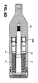
- FIG. 4B is a cross-sectional view A-A of the torque limiting device 10 in the loaded position. In the transparent view above, the loaded positions are shown.
- the handle 16 is turned till one of the insert 40, hereafter referred to as the "first insert 40," is loaded into the hole 26 in the shear component 22.
- the larger spring 42 behind the first insert 40 has a higher spring rate than the ejector pin spring 32, thus over-powering the ejector spring 32 and the first insert 40 advances the ejector pin 30 until its movement is limited by the pin-slot combination.
- the insert 40 is correctly positioned for the "torque-limiting" step.
- FIG. 5A is a top view of the torque limiting device 10 in a shear position.
- the handle 16 will rotate relative to the shear component 22 to an in-between position between "Load” and "Eject".
- FIG. 5B is a cross-sectional view B-B of the torque limiting device 10 in the shear position.
- the front segment 50C of the first insert 40 is shown sheared and retained inside the shearing hole 26A of the shear component 22. Because there is only the one shearing hole 26A on the shear component 22 that is on the same bolt circle as the first insert 40, the first insert 40 will not advance to the next position until the shearing hole 26A is emptied.
- FIG. 5C is an end view of the torque limiting device in the shear position. As shown in FIG. 5C, the section line C-C is disposed at an angle to pass through the loading bores 26B.
- FIG. 5D is a cross-sectional view C-C of the torque limiting device 10 in the shear position. As shown in FIG. 5D, the cross-sectional view C-C transects the loading bore 26B and illustrates how both the first insert 40 and a second insert 40 are essentially prevented from advancing while the shear component 22 is positioned between "Load” and "Eject" position.
- FIG. 6A is a top view of the torque limiting device 10 in an eject position. As shown in FIG. 6A, the handle 16 is rotated into an "Eject" position.
- FIG. 6B is a cross-sectional view C-C of the torque limiting device 10 in the eject position.
- the segment 50C of the first insert 40 that has been sheared off will now advance into ejection chamber of the handle 16. Because of the limit slot in the ejector pin 30 it will not advance into the ejection chamber.
- a cleaning port or clearing port 58 is optionally included to augment ejection. For example, if included, a wire or pin may be inserted to augment the action of the spring 32.
- FIG. 6C is an end view of the torque limiting device 10 in the eject position. As shown in FIG. 6C, the section line E-E is disposed at an angle to pass through the loading bores 26B.
- FIG. 6D is a cross-sectional view E-E of the torque limiting device 10 in the eject position. As shown in FIG. 6D, the cross-sectional view E-E transects the loading bore 26B and illustrates how both the first insert 40 and second insert 40 are essentially prevented from advancing while the shear component 22 is in the eject position.
- FIG. 7A is a top view of the torque limiting device 10 in a second loaded position.
- the handle 16 is now rotated to the next "Load” position.
- FIG. 7B is a cross-sectional view F-F of the torque limiting device 10 in the second loaded position.
- the first segment 50C of a second insert 40 advances into the shear component 22, pushing the ejector pin 30 until it stops. Note that the first segment 50C will not advance until it aligns with the hole 26A in the shear component 22.
- FIG. 8A is a top view of the torque limiting device 10 in a second shear position.
- the handle 16 will be in an in-between position of "Load” and "Eject".
- FIG. 8B is a cross-sectional view G-G of the torque limiting device 10 in the second shear position.
- the front segment 50C of the second insert 40 is shown sheared and retained inside the hole 26A of the shear component 22. Because there is only the one hole on the shear component 22 that is on the same bolt circle as the second insert 40, the second insert 40 will not advance to the next position.
- FIG. 8C is an end view of the torque limiting device 10 in the eject position. As shown in FIG. 8C, the section line H-H is disposed at an angle to pass through the loading bores 26B.
- FIG. 8D is a cross-sectional view H-H of the torque limiting device 10 in the eject position. As shown in FIG. 8D, the cross-sectional view H-H transects the loading bore 26B and illustrates how both the first insert 40 and second insert 40 are essentially prevented from advancing while the shear component 22 is between the load eject positions.
- FIG. 9A is a top view of the torque limiting device 10 in a second eject position. In response to rotating the handle 16 the torque limiting device 10 advances to an "Eject" position.
- FIG. 9B is a cross-sectional view I-I of the torque limiting device 10 in the second eject position.
- the segment 50C of the second insert 40 that has been sheared off will now advance into ejection chamber of the handle 16. Because of the limit slot 34 in the ejector pin 30 it will not advance into the ejection chamber. Note that there are now two separate insert 40 (e.g., the first and second insert 40) segments in two separate ejection chambers.
- FIG. 9C is an end view of the torque limiting device 10 in the second eject position. As shown in FIG. 9C, the section line J-J is disposed at an angle to pass through the loading bores 26B.
- FIG. 9D is a cross-sectional view J-J of the torque limiting device 10 in the second eject position. As shown in FIG. 9D, the cross-sectional view J-J transects the loading bore 26B and illustrates how both the first insert 40 and second insert 40 are essentially prevented from advancing while the shear component 22 is in the eject position.
- FIG. 10A is a cross-sectional view of the torque limiting device 10 in a final eject position. As shown in FIG. 10A, the segments 50C-50E are retained within the collecting bores 26C
- FIG. 10B is a cross-sectional top view of the torque limiting device 10 in the final eject position. As shown in FIG. 10B, the flange 54 is configured to engage a lip or otherwise essentially prevent the insert 40 from progressing further than the final segment.
- FIG. 10C is a cross-sectional top view of the torque limiting device 10 in the final eject position according to another embodiment.
- the torque limiting device 10 according to this particular embodiment is capable of six torque-limiting uses. In other embodiments, the torque limiting device 10 and/or the insert 40 may be configured for more or fewer torque-limiting uses. Once the segments 50C-50n are all sheared off the flange 54 will prevent the insert 40 from advancing further. At this point the device 10 will only spin. The device 10 is also designed to hold all six segments 50A-50n.
- FIG. 11 is an exploded view illustrating removal of the used insert 40 from the torque limiting device 10 of FIG. 1.
- FIG. 12 is a flow diagram illustrating a method 60 of installing a fastener according to an embodiment of the invention.
- the method 60 may be initiated at step 62 in response to installing a torque limiting insert such as the insert 40 in the torque limiting device 10.
- loading sleeves or bores may be accessed.
- the retaining cap 44 may be unscrewed or otherwise removed along with the spring 42 and spring assembly 46 to expose the loading bore 26B and the collecting bore 26C.
- the insert 40 may be positioned in the loading bore 26B and the torque limiting device reassembled.
- the insert 40 installed in the torque limiting device 10 may be selected based upon a predetermined torque limit for a particular fastener that is to be installed.
- a fastener such as a bone screw may have a recommended installation torque of 4 Newton Meters (Nm).
- the insert 40 selected for installation may include a predetermined shear strength that corresponds to 4 Nm of torque.
- the fastener 12 may be installed in the substrate 14.
- a bone screw may be screwed into the bone of a patient.
- the fastener 12 may be coupled to the torque limiting device 10 by a bit and the handle 16 may be rotated until the insert 40 is sheared as shown in FIG. 5A and 5B.
- a severed segment may be ejected from the head 20.
- the shearing hole 26A may be aligned with the collecting bore 26C.
- the segment 50C for example, may be urged by the spring loaded ejector pin 30 and spring 32 into the collecting bore 26C.
- step 68 it may be determined if additional fasteners are to be installed. For example, if an ongoing operational procedure indicates addition fasteners may be utilized, it may be determined if the additional fasteners include essentially the same torque indication at step 70. If no additional fastener installation is indicated, the torque limiting device 10 maybe cleaned at step 78.
- step 70 it may be determined if essentially the same torque limit is indicated. For example, essentially the same torque limit may be indicated in situations utilizing the same type of bone screw being installed into similar boney tissue. If it is determined that essentially the same torque limit is indicated, it may be determined if additional segments 50C-50n remain attached to the insert 40. If it is determined that a different torque limit is indicated, the insert 40 may be exchanged at step 74.
- step 72 it may be determined if more segments remain. For example, if upon rotating the handle 16 relative to the head 20 one full rotation, no segment 50C-50n is loaded into the shearing hole 26A, then it may be determined that no segments remain and the insert 40 may be replaced at step 74. If segments 50C-50n do remain, a next segment may be loaded if not already done so at step 76.
- the insert 40 may be replaced.
- the retaining cap 44 may be unscrewed or otherwise removed along with the spring 42 and spring assembly 46 to expose the loading bore 26B and the collecting bore 26C.
- the insert 40 and any spent segments 50C-50n may be removed via the assistance of gravity by tilting the torque limiting 10. Thereafter, the insert 40 having a torque limit corresponding to a next fastener to be installed in the loading bore 26B as shown in FIG. 3C and the torque limiting device reassembled.
- a next segment 50C-50n may be loaded. For example, if a segment has not already been loaded, the head 20 may be rotated relative to the handle 16 until the load position is obtained as shown in FIGS. 7A and 7B. Following loading, a fastener may be installed at step 64.
- the torque limiting device 10 may be cleaned.
- the torque limiting device 10 may be disassembled as shown in FIG. 11 and the torque limiting device 10 may be washed. Once emptied of inserts 40, the torque limiting device may be reassembled and/or sterilized. In a particular example, the torque limiting device 10 may be autoclaved.
Landscapes
- Health & Medical Sciences (AREA)
- Engineering & Computer Science (AREA)
- Mechanical Engineering (AREA)
- Life Sciences & Earth Sciences (AREA)
- Orthopedic Medicine & Surgery (AREA)
- Surgery (AREA)
- Heart & Thoracic Surgery (AREA)
- Biomedical Technology (AREA)
- Nuclear Medicine, Radiotherapy & Molecular Imaging (AREA)
- Medical Informatics (AREA)
- Molecular Biology (AREA)
- Animal Behavior & Ethology (AREA)
- General Health & Medical Sciences (AREA)
- Public Health (AREA)
- Veterinary Medicine (AREA)
- Details Of Spanners, Wrenches, And Screw Drivers And Accessories (AREA)
- Surgical Instruments (AREA)
Applications Claiming Priority (1)
| Application Number | Priority Date | Filing Date | Title |
|---|---|---|---|
| US83195306P | 2006-07-20 | 2006-07-20 |
Publications (1)
| Publication Number | Publication Date |
|---|---|
| EP1880802A2 true EP1880802A2 (de) | 2008-01-23 |
Family
ID=38596174
Family Applications (1)
| Application Number | Title | Priority Date | Filing Date |
|---|---|---|---|
| EP07251074A Withdrawn EP1880802A2 (de) | 2006-07-20 | 2007-03-14 | Halbautomatische Einweg-Drehmomentbegrenzungsvorrichtung und Verfahren |
Country Status (5)
| Country | Link |
|---|---|
| US (1) | US20080016990A1 (de) |
| EP (1) | EP1880802A2 (de) |
| JP (1) | JP2008023697A (de) |
| CA (1) | CA2581793A1 (de) |
| MX (1) | MX2007008102A (de) |
Cited By (12)
| Publication number | Priority date | Publication date | Assignee | Title |
|---|---|---|---|---|
| WO2009016471A1 (de) * | 2007-07-30 | 2009-02-05 | Zrinski Ag | Drehmomentschlüssel, insbesondere für den medizinischen bereich |
| WO2013143563A1 (en) * | 2012-03-30 | 2013-10-03 | Stryker Trauma Ag | Torque-limiting assembly for a surgical powertool |
| WO2015026889A1 (en) * | 2013-08-22 | 2015-02-26 | Ossur Hf | Torque limiting tool and method for using the same |
| US9125730B2 (en) | 2011-10-31 | 2015-09-08 | Ossur Hf | Orthopedic device for dynamically treating the knee |
| US9220624B2 (en) | 2010-09-16 | 2015-12-29 | Ossur Hf | Posterior cruciate ligament support brace |
| US9351864B2 (en) | 2013-01-25 | 2016-05-31 | Ossur Hf | Orthopedic device having a dynamic control system |
| US9539135B2 (en) | 2013-01-25 | 2017-01-10 | Ossur Hf | Orthopedic device having a dynamic control system and method for using the same |
| US10143581B2 (en) | 2013-06-21 | 2018-12-04 | Ossur Hf | Dynamic tension system for orthopedic device |
| US10413437B2 (en) | 2013-01-25 | 2019-09-17 | Ossur Iceland Ehf | Orthopedic device having a dynamic control system and method for using the same |
| US10512305B2 (en) | 2014-07-11 | 2019-12-24 | Ossur Hf | Tightening system with a tension control mechanism |
| US10653546B2 (en) | 2014-10-31 | 2020-05-19 | Ossur Hf | Orthopedic device having a dynamic control system |
| US11547590B2 (en) | 2017-11-27 | 2023-01-10 | Ossur Iceland Ehf | Orthopedic device having a suspension element |
Families Citing this family (10)
| Publication number | Priority date | Publication date | Assignee | Title |
|---|---|---|---|---|
| US8028608B2 (en) * | 2009-04-07 | 2011-10-04 | Depuy Products, Inc. | Torque-limiting fastener driver |
| US9358672B2 (en) | 2010-05-18 | 2016-06-07 | Gauthier Biomedical, Inc. | Electronic torque wrench |
| US8485075B1 (en) | 2010-05-18 | 2013-07-16 | Gauthier Biomedical, Inc. | Electronic torque wrench |
| CN103862419B (zh) * | 2012-12-11 | 2016-06-22 | 苏州宝时得电动工具有限公司 | 一种动力工具 |
| DE102014105078A1 (de) * | 2014-04-09 | 2015-10-15 | Weber Instrumente Gmbh & Co. Kg | Werkzeugvorrichtung, insbesondere Handwerkzeugvorrichtung |
| CN106141965B (zh) * | 2015-04-21 | 2018-03-30 | 麦递途医疗科技(上海)有限公司 | 直筒精确扭力限定扳手 |
| JP7191700B2 (ja) | 2016-06-07 | 2022-12-19 | プロ-デツクス・インコーポレイテツド | トルク制限スクリュードライバ装置、システムおよび方法 |
| CN112566754B (zh) | 2018-08-20 | 2023-04-18 | 普罗德克斯有限公司 | 扭矩限制装置、系统和方法 |
| US11389942B1 (en) * | 2019-01-08 | 2022-07-19 | Seaspine Orthopedics Corporation | Securing mechanism for a shaft |
| US12144320B2 (en) | 2019-02-08 | 2024-11-19 | Allflex Australia Pty Ltd | Electronic animal identification tag reader synchronisation |
Family Cites Families (16)
| Publication number | Priority date | Publication date | Assignee | Title |
|---|---|---|---|---|
| US1970071A (en) * | 1933-09-06 | 1934-08-14 | Carl O Bengtsson | Nonremovable display device |
| US2740315A (en) * | 1953-03-03 | 1956-04-03 | Illinois Tool Works | Thread cutting screw with frangible shank |
| US3191486A (en) * | 1962-10-29 | 1965-06-29 | Martin Marietta Corp | Automatic torque indicating and applying devices |
| US3331267A (en) * | 1965-08-30 | 1967-07-18 | Fred R Tietge | Wrench having a reduced portion which fails at the desired torque |
| US3595124A (en) * | 1969-05-19 | 1971-07-27 | Keystone Consolidated Ind Inc | Controlled torque bolt |
| US3830119A (en) * | 1973-08-08 | 1974-08-20 | Sweeney Mfg Co | Shear-off output shaft for torque multiplier |
| US4215600A (en) * | 1978-10-12 | 1980-08-05 | Kesselman David A | Torque limiter for use with off-the-shelf fastening elements |
| US4420281A (en) * | 1981-10-05 | 1983-12-13 | Amp, Incorporated | Fail-safe mechanism |
| US4838264A (en) * | 1987-08-18 | 1989-06-13 | Bremer Orthopedics, Inc. | Torque limiting device for use with bone penetrating pins |
| US5295831A (en) * | 1992-09-17 | 1994-03-22 | Impla-Med, Inc. | Disposable torque wrench for dental components |
| US5347894A (en) * | 1993-05-28 | 1994-09-20 | Pmt Corporation | Torque limiting device |
| BR9408540A (pt) * | 1994-01-26 | 1997-05-20 | Vermont American Corp | Ferramenta de inserçao e método de produçao de uma ferramenta de inserçao |
| US5571014A (en) * | 1994-09-02 | 1996-11-05 | Snap-On Technologies, Inc. | Disposable torque limiting wrench |
| US6308598B1 (en) * | 1998-11-23 | 2001-10-30 | O'neil Michael J. | Modular torque-limiting driver system for medical applications |
| JP2001054876A (ja) * | 1999-08-17 | 2001-02-27 | Nec Corp | 締結部品の締め付けトルク管理用治具 |
| US6499358B1 (en) * | 1999-12-27 | 2002-12-31 | Sherwood Services Ag | Apparatus for applying a controlled amount of torque |
-
2007
- 2007-03-08 CA CA002581793A patent/CA2581793A1/en not_active Abandoned
- 2007-03-14 EP EP07251074A patent/EP1880802A2/de not_active Withdrawn
- 2007-03-20 JP JP2007073518A patent/JP2008023697A/ja active Pending
- 2007-03-29 US US11/727,972 patent/US20080016990A1/en not_active Abandoned
- 2007-06-29 MX MX2007008102A patent/MX2007008102A/es not_active Application Discontinuation
Cited By (21)
| Publication number | Priority date | Publication date | Assignee | Title |
|---|---|---|---|---|
| EP2025296A1 (de) | 2007-07-30 | 2009-02-18 | Zrinski AG | Drehmomentschlüssel, insbesondere für den medizinischen Bereich |
| WO2009016471A1 (de) * | 2007-07-30 | 2009-02-05 | Zrinski Ag | Drehmomentschlüssel, insbesondere für den medizinischen bereich |
| US9220624B2 (en) | 2010-09-16 | 2015-12-29 | Ossur Hf | Posterior cruciate ligament support brace |
| US9770356B2 (en) | 2011-10-31 | 2017-09-26 | Ossur Hf | Orthopedic device for dynamically treating the knee |
| US10898363B2 (en) | 2011-10-31 | 2021-01-26 | Ossur Hf | Orthopedic device for dynamically treating the knee |
| US9763821B2 (en) | 2011-10-31 | 2017-09-19 | Ossur Iceland Ehf | Orthopedic device for dynamically treating the knee |
| US9125730B2 (en) | 2011-10-31 | 2015-09-08 | Ossur Hf | Orthopedic device for dynamically treating the knee |
| WO2013143563A1 (en) * | 2012-03-30 | 2013-10-03 | Stryker Trauma Ag | Torque-limiting assembly for a surgical powertool |
| US9937009B2 (en) | 2012-03-30 | 2018-04-10 | Stryker European Holdings I, Llc | Torque-limiting assembly for a surgical powertool |
| US10413437B2 (en) | 2013-01-25 | 2019-09-17 | Ossur Iceland Ehf | Orthopedic device having a dynamic control system and method for using the same |
| US11464662B2 (en) | 2013-01-25 | 2022-10-11 | Ossur Iceland Ehf | Orthopedic device having a dynamic control system and method for using the same |
| US9351864B2 (en) | 2013-01-25 | 2016-05-31 | Ossur Hf | Orthopedic device having a dynamic control system |
| US9539135B2 (en) | 2013-01-25 | 2017-01-10 | Ossur Hf | Orthopedic device having a dynamic control system and method for using the same |
| US10143581B2 (en) | 2013-06-21 | 2018-12-04 | Ossur Hf | Dynamic tension system for orthopedic device |
| US11160679B2 (en) | 2013-06-21 | 2021-11-02 | Ossur Hf | Dynamic tension system for orthopedic device |
| US9597786B2 (en) | 2013-08-22 | 2017-03-21 | Ossur Hf | Torque limiting tool and method for using the same |
| WO2015026889A1 (en) * | 2013-08-22 | 2015-02-26 | Ossur Hf | Torque limiting tool and method for using the same |
| US10512305B2 (en) | 2014-07-11 | 2019-12-24 | Ossur Hf | Tightening system with a tension control mechanism |
| US10653546B2 (en) | 2014-10-31 | 2020-05-19 | Ossur Hf | Orthopedic device having a dynamic control system |
| US11628081B2 (en) | 2014-10-31 | 2023-04-18 | Ossur Hf | Orthopedic device having a dynamic control system |
| US11547590B2 (en) | 2017-11-27 | 2023-01-10 | Ossur Iceland Ehf | Orthopedic device having a suspension element |
Also Published As
| Publication number | Publication date |
|---|---|
| MX2007008102A (es) | 2009-01-07 |
| CA2581793A1 (en) | 2008-01-20 |
| US20080016990A1 (en) | 2008-01-24 |
| JP2008023697A (ja) | 2008-02-07 |
Similar Documents
| Publication | Publication Date | Title |
|---|---|---|
| EP1880802A2 (de) | Halbautomatische Einweg-Drehmomentbegrenzungsvorrichtung und Verfahren | |
| EP2097028B1 (de) | Kalibrierter mechanischer orthopädischer antrieb mit verschleisskompensiertem drehmomentbegrenzungsmechanismus | |
| EP2238937B1 (de) | Werkzeug zur Verwendung mit einem Knochenanker, insbesondere für die Wirbelsäulenchirurgie | |
| US20220304732A1 (en) | Techniques and instruments for placement of orthopedic implants relative to bone features | |
| US7938046B2 (en) | Torque-limiting device | |
| EP2675595B1 (de) | Internationale anwendung für eine verbesserte vorrichtung mit hohem drehmoment | |
| EP2566411B1 (de) | Vorrichtung mit ultrahohem drehmoment | |
| US20100107829A1 (en) | Torque limiting driver | |
| US9107721B2 (en) | Universal bone screw screwdriver | |
| EP1880801A1 (de) | Multibit-Schrauber mit drehbarer Hülse | |
| EP1955820A1 (de) | Multibit-Antrieb mit Senker für Trockenbauwand | |
| US20150148176A1 (en) | Torque-limiting assembly for a surgical powertool | |
| US20230301664A1 (en) | Multiple Connection Drive Shaft | |
| BE1022426B1 (nl) | Combinatie schroevendraaier en koppelbegrenzingssysteem | |
| ES2446541T3 (es) | Llave dinamométrica, en particular para el campo de la medicina | |
| US6543317B1 (en) | Screw holder and torquing tool | |
| US20170020591A1 (en) | Tool device, in particular hand-held tool device, featuring torque limitation | |
| EP3359065B1 (de) | Getriebelose drehmomentbegrenzte in-line-vorrichtung | |
| CN215129966U (zh) | 持取装置及具有其的自断螺塞组件 | |
| WO2019157379A1 (en) | Adjustable disposable torque limiting mount and device | |
| EP2948078B1 (de) | Einweg-drehmomentvorrichtungen mit verstärktem kunststoff |
Legal Events
| Date | Code | Title | Description |
|---|---|---|---|
| PUAI | Public reference made under article 153(3) epc to a published international application that has entered the european phase |
Free format text: ORIGINAL CODE: 0009012 |
|
| AK | Designated contracting states |
Kind code of ref document: A2 Designated state(s): AT BE BG CH CY CZ DE DK EE ES FI FR GB GR HU IE IS IT LI LT LU LV MC MT NL PL PT RO SE SI SK TR |
|
| AX | Request for extension of the european patent |
Extension state: AL BA HR MK YU |
|
| 17P | Request for examination filed |
Effective date: 20080625 |
|
| STAA | Information on the status of an ep patent application or granted ep patent |
Free format text: STATUS: THE APPLICATION HAS BEEN WITHDRAWN |
|
| 18W | Application withdrawn |
Effective date: 20090522 |