EP1880459B2 - Système de commande de la puissance d'un parc eolien - Google Patents
Système de commande de la puissance d'un parc eolien Download PDFInfo
- Publication number
- EP1880459B2 EP1880459B2 EP06761928.8A EP06761928A EP1880459B2 EP 1880459 B2 EP1880459 B2 EP 1880459B2 EP 06761928 A EP06761928 A EP 06761928A EP 1880459 B2 EP1880459 B2 EP 1880459B2
- Authority
- EP
- European Patent Office
- Prior art keywords
- voltage
- wind farm
- power factor
- power
- wind
- Prior art date
- Legal status (The legal status is an assumption and is not a legal conclusion. Google has not performed a legal analysis and makes no representation as to the accuracy of the status listed.)
- Active
Links
Images


Classifications
-
- H—ELECTRICITY
- H02—GENERATION; CONVERSION OR DISTRIBUTION OF ELECTRIC POWER
- H02M—APPARATUS FOR CONVERSION BETWEEN AC AND AC, BETWEEN AC AND DC, OR BETWEEN DC AND DC, AND FOR USE WITH MAINS OR SIMILAR POWER SUPPLY SYSTEMS; CONVERSION OF DC OR AC INPUT POWER INTO SURGE OUTPUT POWER; CONTROL OR REGULATION THEREOF
- H02M7/00—Conversion of ac power input into dc power output; Conversion of dc power input into ac power output
- H02M7/42—Conversion of dc power input into ac power output without possibility of reversal
- H02M7/44—Conversion of dc power input into ac power output without possibility of reversal by static converters
- H02M7/48—Conversion of dc power input into ac power output without possibility of reversal by static converters using discharge tubes with control electrode or semiconductor devices with control electrode
- H02M7/53—Conversion of dc power input into ac power output without possibility of reversal by static converters using discharge tubes with control electrode or semiconductor devices with control electrode using devices of a triode or transistor type requiring continuous application of a control signal
- H02M7/537—Conversion of dc power input into ac power output without possibility of reversal by static converters using discharge tubes with control electrode or semiconductor devices with control electrode using devices of a triode or transistor type requiring continuous application of a control signal using semiconductor devices only, e.g. single switched pulse inverters
- H02M7/539—Conversion of dc power input into ac power output without possibility of reversal by static converters using discharge tubes with control electrode or semiconductor devices with control electrode using devices of a triode or transistor type requiring continuous application of a control signal using semiconductor devices only, e.g. single switched pulse inverters with automatic control of output wave form or frequency
- H02M7/5395—Conversion of dc power input into ac power output without possibility of reversal by static converters using discharge tubes with control electrode or semiconductor devices with control electrode using devices of a triode or transistor type requiring continuous application of a control signal using semiconductor devices only, e.g. single switched pulse inverters with automatic control of output wave form or frequency by pulse-width modulation
-
- H—ELECTRICITY
- H02—GENERATION; CONVERSION OR DISTRIBUTION OF ELECTRIC POWER
- H02J—CIRCUIT ARRANGEMENTS OR SYSTEMS FOR SUPPLYING OR DISTRIBUTING ELECTRIC POWER; SYSTEMS FOR STORING ELECTRIC ENERGY
- H02J3/00—Circuit arrangements for ac mains or ac distribution networks
- H02J3/18—Arrangements for adjusting, eliminating or compensating reactive power in networks
- H02J3/1821—Arrangements for adjusting, eliminating or compensating reactive power in networks using shunt compensators
- H02J3/1835—Arrangements for adjusting, eliminating or compensating reactive power in networks using shunt compensators with stepless control
-
- H—ELECTRICITY
- H02—GENERATION; CONVERSION OR DISTRIBUTION OF ELECTRIC POWER
- H02J—CIRCUIT ARRANGEMENTS OR SYSTEMS FOR SUPPLYING OR DISTRIBUTING ELECTRIC POWER; SYSTEMS FOR STORING ELECTRIC ENERGY
- H02J3/00—Circuit arrangements for ac mains or ac distribution networks
- H02J3/18—Arrangements for adjusting, eliminating or compensating reactive power in networks
- H02J3/1878—Arrangements for adjusting, eliminating or compensating reactive power in networks using tap changing or phase shifting transformers
-
- H—ELECTRICITY
- H02—GENERATION; CONVERSION OR DISTRIBUTION OF ELECTRIC POWER
- H02J—CIRCUIT ARRANGEMENTS OR SYSTEMS FOR SUPPLYING OR DISTRIBUTING ELECTRIC POWER; SYSTEMS FOR STORING ELECTRIC ENERGY
- H02J3/00—Circuit arrangements for ac mains or ac distribution networks
- H02J3/38—Arrangements for parallely feeding a single network by two or more generators, converters or transformers
- H02J3/381—Dispersed generators
-
- H—ELECTRICITY
- H02—GENERATION; CONVERSION OR DISTRIBUTION OF ELECTRIC POWER
- H02J—CIRCUIT ARRANGEMENTS OR SYSTEMS FOR SUPPLYING OR DISTRIBUTING ELECTRIC POWER; SYSTEMS FOR STORING ELECTRIC ENERGY
- H02J2300/00—Systems for supplying or distributing electric power characterised by decentralized, dispersed, or local generation
- H02J2300/20—The dispersed energy generation being of renewable origin
- H02J2300/28—The renewable source being wind energy
-
- Y—GENERAL TAGGING OF NEW TECHNOLOGICAL DEVELOPMENTS; GENERAL TAGGING OF CROSS-SECTIONAL TECHNOLOGIES SPANNING OVER SEVERAL SECTIONS OF THE IPC; TECHNICAL SUBJECTS COVERED BY FORMER USPC CROSS-REFERENCE ART COLLECTIONS [XRACs] AND DIGESTS
- Y02—TECHNOLOGIES OR APPLICATIONS FOR MITIGATION OR ADAPTATION AGAINST CLIMATE CHANGE
- Y02E—REDUCTION OF GREENHOUSE GAS [GHG] EMISSIONS, RELATED TO ENERGY GENERATION, TRANSMISSION OR DISTRIBUTION
- Y02E10/00—Energy generation through renewable energy sources
- Y02E10/70—Wind energy
- Y02E10/76—Power conversion electric or electronic aspects
-
- Y—GENERAL TAGGING OF NEW TECHNOLOGICAL DEVELOPMENTS; GENERAL TAGGING OF CROSS-SECTIONAL TECHNOLOGIES SPANNING OVER SEVERAL SECTIONS OF THE IPC; TECHNICAL SUBJECTS COVERED BY FORMER USPC CROSS-REFERENCE ART COLLECTIONS [XRACs] AND DIGESTS
- Y02—TECHNOLOGIES OR APPLICATIONS FOR MITIGATION OR ADAPTATION AGAINST CLIMATE CHANGE
- Y02E—REDUCTION OF GREENHOUSE GAS [GHG] EMISSIONS, RELATED TO ENERGY GENERATION, TRANSMISSION OR DISTRIBUTION
- Y02E40/00—Technologies for an efficient electrical power generation, transmission or distribution
- Y02E40/30—Reactive power compensation
Definitions
- the present invention relates to a wind farm comprising a number of wind turbines connected to a utility grid, which is to be driven with a requested power factor or a requested reactive power, and to a method of controlling the dynamic power factor or reactive power of the wind farm.
- the reactive power is the power needed by inductive and capacitive users to build up their magnetic and electric fields, respectively. With an alternating current such magnetic and electric fields will be built up and down periodically, which leads to a reactive power flow from and to the electric generators.
- the power factor is the cosine of the phase angle between voltage and current.
- Dynamic power factor control of wind farms is often implemented with capacitors banks mounted in individual wind turbines. Capacitors are switched on and off the grid to provide such reactive power as is required to meet the specified power factor. Dynamic power factor control may also be implemented by an arrangement where the individual wind turbines are equipped with a power electronic converter that converts part or whole of the electricity supplied by the wind turbine. The power electronic converter of the individual wind turbine is programmed to control the power factor of the electricity supplied by the wind turbine.
- the desired power factor is typically provided as a signal from a central SCADA (Supervise Control and Data Acquisition) system.
- the utility system operator dispatches a request to the wind farm for a certain power factor and the central SCADA system forwards the power factor request to the individual wind turbines, either directly or after modification, to compensate for the power factor contribution of the wind farm electrical infrastructure.
- the power factor is controlled locally at the individual wind turbines by adjustment of the power factor of the electricity supplied by the individual wind turbines to correspond to the power factor requested by the SCADA system.
- Such an arrangement for dynamic power control is, e. g., described in US 5,083,039 , which describes a wind turbine with dynamic power factor control, sending control signals to power electronic converters of wind turbines.
- the power electronic converters are then locally controlled such that the power factor delivered by the local wind turbine is shifted through changing the ratio of active and reactive current supplied to the grid by the inverter module of the power electronic converter.
- a dynamic power factor control system as outlined above requires a SCADA system with functional and fast-reacting connections to the individual wind turbines. If the individual communication of the wind farm is slow or deficient, the dynamic power control will not function faultlessly. Further, unless all turbines are operating at the same active power output, which will rarely be the case if the wind speed is not sufficiently high to cause all wind turbines of the farm to operate at rated capacity, the reactive power supplied by an individual wind turbine will change proportionally with the active power supplied by the individual wind turbine. This means that some wind turbines will provide significantly larger proportion of reactive power than others, which in turn leads to current flow in the wind farm that is less balanced and causes higher losses than what could be achieved with more balanced current flow.
- the first objective is solved by a method controlling the dynamic power factor or the reactive power of a wind farm comprising a number of wind turbines, as it is claimed in claim 1.
- the second objective is solved by a wind farm which comprises a number of wind turbines, as it is claimed in claim 7.
- the depending claims define further developments of the present invention.
- the invention defines a method of controlling the dynamic power factor or the reactive power of a wind farm.
- the wind farm comprises a number of wind turbines connected to a utility grid which is to be driven with a requested power factor or requested reactive power.
- the output voltage of the electricity supplied by an individual wind turbine of the wind farm is controlled to a specific voltage set point.
- the wind farm power factor or the wind farm reactive power is measured and compared with the power factor requested for the utility grid or the reactive power requested for the utility grid, respectively, and the ratio of the wind farm voltage to the utility grid voltage is adjusted. Further, the output voltage of the individual wind turbines is regulated to correspond to the specific voltage set point.
- At least the steps of adjusting the ratio of the wind farm voltage to the utility grid voltage and of regulating the output voltage of the individual wind turbines to the specific voltage set point are performed until the power factor or the reactive power of the electricity supplied by the wind farm corresponds to the requested power factor or the requested reactive power, respectively.
- the wind farm further comprises a substation connecting the wind farm to the utility grid.
- the substation includes or is connected to a substation controller which is connected to or includes the measuring means for receiving a difference signal representing the deviation of the wind farm power factor from the requested power factor or the deviation of the wind farm reactive power from the requested reactive power, respectively, and to the adjusting means for outputting an adjustment signal.
- the substation controller establishes an adjustment signal on the basis of the received difference signal, in which the substation controller iteratively establishes adjustment signals on the basis of an iteratively received difference signal.
- each wind turbine Upon a change of the ratio of the wind farm voltage to the utility grid voltage, each wind turbine will automatically regulate the voltage of the wind turbine to match the preset voltage. This regulation is done by varying the ratio of active power to reactive power delivered by the individual wind turbine. This changes of the ratios of reactive power to active power at the individual wind turbine collectively changes the ratio of reactive power to active power of the electricity supplied by the wind form. This continues until the desired power factor or reactive power, respectively, is reached.
- measuring the wind farm power factor and comparing it with the requested power factor or of measuring the wind farm reactive power and comparing it with the requested reactive power, respectively may also be repeated when repeating the adjustment of the ratio of the wind farm voltage to the utility grid voltage and the regulation of the output voltage of the individual wind turbines. Further, the steps may be repeated in discrete steps or continuously until the power factor of the electricity supplied by the wind farm corresponds to the requested power factor, or the reactive power of the electricity supplied by the wind farm corresponds to the requested reactive power, respectively.
- a main transformer tap For the step of adjusting said ratio of the wind farm voltage to the utility grid voltage a main transformer tap is used.
- a utility system operator might desire a more precise regulation of the power factor than can be achieved by incremental, or stepwise, adjustment of the ratio of the wind farm voltage to the utility grid voltage by means of the main transformer tap changer.
- Such more precise regulation can be achieved if the ratio of the wind farm voltage to the utility grid voltage is additionally adjusted by the use of a supplementary dynamic power factor control, e.g. in the form of an adjustable capacitor bank.
- the individual wind turbines are equipped with power electronic converters that convert part or the whole of the electricity supplied by the wind turbine, the power electronic converters of the individual wind turbines are programmed to control the output voltage of the electricity supplied by their wind turbines to said specific voltage set point and to regulate the output voltage of their wind turbine to correspond to said specific voltage set point.
- the power electronic converters of the individual wind turbines are programmed to control the output voltage of the electricity supplied by their wind turbines to said specific voltage set point and to regulate the output voltage of their wind turbine to correspond to said specific voltage set point.
- this implementation of regulating the output voltage of an individual wind turbine to a voltage set point can be achieved with relatively small effort.
- the inventive method allows for more flexibility if the voltage set point to which the output voltage of the individual wind turbines is regulated is adjustable.
- An inventive wind farm with a number of wind turbines for being collectively connected to a utility grid comprises individual wind turbines equipped with a power electronic converter for converting part or the whole of the electricity supplied by the wind turbine.
- the power electronic converters are equipped with controllers programmed for controlling the output voltage of the electricity supplied by the wind turbine to a specific voltage set point. It further comprises means for measuring the wind farm power factor or the wind farm reactive power and comparing it with a requested power factor or a requested reactive power, respectively. In addition, it comprises adjusting means for adjusting the ratio of the wind farm voltage to the utility grid voltage.
- the individual wind turbines are equipped with regulating means which are programmed for regulating the output voltage at the individual wind turbine to correspond to the specific voltage set point.
- the inventive wind farm is designed to perform the inventive method of controlling the dynamic power factor or the reactive power of the wind farm.
- the requested power factor or the requested reactive power does not need to be communicated to the controllers of the power electronic converters of the individual wind turbines. Only an adjustment signal for adjusting the ratio of wind farm voltage to the utility grid voltages needs to be communicated to the wind farm at, e.g., a substation level.
- the output voltage of the individual wind turbines changes as well.
- the regulating means in the controllers of the power electronic converters then regulates the output voltage of each wind farm to correspond to the specific voltage set point.
- the wind farm comprises a substation connecting it to the utility grid.
- the substation includes a substation controller or is connected to a substation controller.
- the substation controller is connected to the measuring means for receiving difference signals representing a deviation of the wind farm power factor from the requested power factor, or a deviation of the wind farm reactive power from the requested reactive power, respectively, and to the adjusting means for outputting an adjustment signal. It is programmed to establish the adjustment signal on the basis of the received difference signal. This development allows for regulating the ratio of the wind farm voltage to the utility grid voltage to a specific ratio set point.
- the substation controller is programmed to iteratively establish adjustment signals on the basis of successively received difference signals. By iteratively establishing adjustment signals, stepwise changes in the ratio of the wind farm voltage to the utility grid voltage can be kept relatively small so that the regulation of the output voltage in the individual wind turbines also requires only small steps.
- a main transformer with at least to taps and a tap changer are used as the adjustment means for adjusting the ratio of the wind farm voltage to the utility grid voltage.
- the utility system operator might desire more precise regulation of the power factor than can be achieved by the incremental, or stepwise, adjustment of the ratio of the wind farm voltage to the utility grid voltage by means of the main transformer tap change.
- More precise regulation can be achieved by the addition of a supplementary dynamic power factor control system, e.g. in the form of an adjustable capacitor bank.
- the reactive power capacity of the supplementary dynamic power factor control system should advantageously correspond to the change in reactive power delivered from the wind farm, which results from the change in the ratio of the wind farm voltage to the utility grid voltage caused by one tap change at the main transformer. This allows for a more continuous variation of power factor or reactive power over the whole range provided by the main transformer.
- the power electronic converters of the individual wind turbines may comprise an inverter with an inverter input which is connected to a DC link of the power electronic converter and an inverter output which is connected - either directly or indirectly - to the substation. It then further comprises an inverter controller which is programmed for controlling the output of the inverter to said specific voltage set points. This allows for using the power electric converter to regulate the output voltages of the wind turbine to said specific voltage set point, i.e. to serve as the regulating means for regulating the output voltage of the individual wind turbine to correspond to said voltage set point.
- the inverter may comprise a number of switches connecting an inverter input to an inverter output.
- the controller then comprises:
- the desired output voltage at the individual wind turbine can be set to correspond to said specific voltage set point.
- the wind farm may comprise a set point adjustment unit.
- This unit is connected to the substation for receiving a set point signal representing a certain value for said voltage set point from the sub station and to the regulation means of individual wind turbines, e.g. to the inverter controllers of power electric converters, for delivering a set point signal to them which causes the voltage set point to be adjusted to the value represented by the set point signal.
- the operation of the wind farm can be adjusted to a broad a range of conditions.
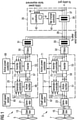
- Fig. 1 shows a wind farm arrangement for carrying out a power factor control according to the invention.
- the wind farm is indicated by two wind turbines 1, 3, each comprising a rotor with a rotor shaft transmitting the rotational momentum of the turning rotor 5, 7 to a gear box 13, 15.
- a gear box 13 15
- a transmission of the rotation to an output shaft 17, 19 with a certain transmission ratio takes place.
- the output shaft 17, 19 is fixed to the rotor of an AC generator 21, 23 which transforms the mechanical power provided by the rotation of the output shaft 17, 19 into the electrical power.
- the AC generator may either be a synchronous generator or an asynchronous generator.
- a synchronous generator the rotor rotates with the same rotational frequency as a rotating magnetic field produced by a stator of the generator.
- the rotational frequencies of the stator's magnetic field and the rotor are different. The difference in rotational frequency is described by the slip of the generator.
- the generators 21, 23 are variable speed generators, i.e. the rotational speed of the rotor is allowed to vary depending on the wind conditions.
- each wind turbine 1, 3 is equipped with a power electronic converter 25, 27 which converts parts or the whole of the varying frequency electricity delivered by the generators 21, 23 into an electrical power having a fixed frequency which is adapted to the utility grid.
- the power electronic converters 25, 27 control the output voltage of the electricity supplied by the wind turbine to correspond to a specific voltage set point. Details of the power electric converters 25, 27 will be explained later.
- the individual wind turbines 1, 3 are connected to an internal grid 29 with an intermediate voltage through filters 30, 32 and transformers 31, 33.
- the internal grid 29 is connected, via a substation 35, to a utility grid which is to be operated with a certain power factor requested by the utility system operator.
- the wind farm which is schematically shown in Fig. 1 , is to be operated with power factor control, i.e. the wind farm delivers a certain power factor on request by the utility system operator.
- the power factor supplied to utility grid can be controlled at the sub station level by a combination of a voltage control at the individual wind turbines of the wind farm, voltage control at the substation and, as an option, a capacitor bank.
- the individual wind turbine invertors will automatically regulate the ratio of active and reactive power supplied by the inverter to maintain the output voltage defined by the voltage set point while, at the same time, supplying the active power defined by the active power controller.
- the change of the ratio of active to reactive power at the individual inverter level will collectively change the power factor of the electricity supplied by the wind farm.
- the power factor of the electricity supplied by the wind farm can be regulated to match the power factor requested by the utility system operator based upon the change of the reactive power output from the individual inverters, i.e. from the individual wind turbines, resulting from changes of the ratio of the wind farm voltage to the utility grid voltage, and the reactive power supplied by the power factor control system.
- the wind farm power factor is measured at the substation level and compared with the power factor requested by the utility system operator. Then, the ratio of the wind farm voltage, at the sub station's 35 output 37, to the utility grid voltage is adjusted at the sub station 35 level. This change of the ratio of the wind farm voltage to the utility grid voltage causes a change of the output voltage at the individual wind turbines. Therefore, the output voltage at the individual wind turbines is regulated by the power electronic converters 25, 27 to correspond again to the specific voltage set point.
- the substation 35 comprises a tap changer which allows for changing the voltage output by the main transformer 39.
- the inductance of the transformer also changes, which in turn changes the phase angle between the voltage and the current supplied by the wind farm to the utility grid.
- the power factor changes, too.
- the power factor is the ratio of the reactive power supplied by the wind farm to the square root of the square of the active power plus the square of the reactive power supplied by the wind farm.
- a power factor of one means that no reactive power is present and the supplied power contains only active power and corresponds to a phase difference between the voltage and the current of zero degrees, since the power factor is given by the cosine of the phase difference between the voltage and the current.
- a phase different of 90° i.e. a power factor of zero, means that only reactive power is delivered to the utility grid by the wind farm.
- the substation 35 further comprises a tap change controller 41 acting on the tap changer of the main transformer 39 and a power factor controller 43 acting on the tap change controller 41.
- the power factor controller 43 receives the request for a certain power factor by the utility system operator through an input line 45.
- the power factor controller 43 includes a measurement unit 47 which is connected to the substation's output 37 for measuring the phase difference between the output voltage and the output current of the wind farm. Based on the measured phase difference, the power factor controller 43 establishes the actual power factor of the electricity supplied by the wind farm and compares it to the power factor requested by the utility operator through the input line 45. On the basis of the difference between a requested power factor and the actual power factor of the wind farm, the power factor control signal is established and delivered to the tap change controller 41.
- the tap change controller 41 determines a ratio of the wind farm voltage to the utility grid voltage which produces a power factor coming closest to the requested power factor. By setting the according tap the ratio is adjusted. The adjustment may be done stepwise or in a continuous process.
- the adjustment of the ratio of the wind farm voltage to the utility grid voltage by means of the main transformer's tap changer leads to a change of the voltage in the internal grid 29 and, in turn, to a change of the voltage at the output of the power electric converters 25, 27.
- the power electronic converters 25, 27 are programmed to control the output voltages of the electricity supplied by the respective wind turbines to correspond to a specific voltage set point
- the adjustment of the ratio of the wind farm voltage to the utility grid voltage results in a regulating action of the power electronic converters 25, 27 for regulating the output voltages at the individual wind turbines until the voltage output by the power electronic converter corresponds again to the voltage set point.
- the wind farm power factor is measured again and compared again with the power factor requested by the utility system operator.
- the difference between the wind farm power factor and the request power factor is small enough, i.e. is smaller than a preset deviation
- the method is finished.
- the difference is not small enough, i.e. is bigger than the preset maximum deviation
- the ratio of the wind farm voltage to the utility grid voltage is adjusted again by means of the main transformer's 39 tap changer, and the output voltages at the individual wind turbine are regulated again by the power electronic converters 25, 27 to correspond to the specific voltage set point. This procedure is repeated as long as the measured difference between the wind farm power factor and the requested power factor is bigger than the allowed maximum deviation anymore.
- control of the dynamic power factor is performed iterative i.e. stepwise with reducing the difference between the wind farm power factor and the requested power factor in each step, it may also be performed continuously, if the substation 35 allows for continuously varying the wind farm voltage at the substation output 37.
- the regulation of the output voltage of the electricity supplied by the wind turbines will be described next.
- the output voltage is controlled by the power electronic converters 25, 27 of the individual wind turbines 1, 3.
- the power electronic converters 25, 27 each comprise an active rectifier 49, 51 for producing a DC voltage from the variable frequency AC voltage provided by the wind turbines, an inverter producing a fixed frequency AC voltage from the DC voltage, and a DC link 57, 59 connecting the active rectifier 49, 51 with the inverter 53, 55.
- Each power electronic converter 25, 27 further includes a generator controller 61, 63 which controls the torque reacted by the generator 21, 23 by controlling the stator current or stator voltage of the generator 21, 23.
- the control signal output to the active rectifier 49, 51 is established on the basis of the desired power to be provided to the grid, the voltage of the DC link and the shaft speed of the rotor.
- the inverter controller 73, 75 receives the voltage level on the DC link 57, 59 and the voltage level at the inverter output. It further receives an active power control signal from an active power controller 69, 71, which controls the active power, output by the power electronic converters 25, 27, to a requested active power. Moreover, the inverter controller 73, 75 controls the output voltage of the inverter 53, 55 to a preset voltage set point. The active power and the voltage are controlled by means of pulse width modulated commutation signals for active switches of the inverter 53, 55.
- each pair of active switching devices 77 includes two isolated gate bipolar transistors as active switching devices 77.
- the pairs of active switching devices 77 are connected between the two lines of the DC link 57.
- the three lines of the inverter output 79 are each connected to a different one of the pairs of active switching devices 77,in the middle between the switching devices 77.
- the DC voltage on the voltage link 57 can be transformed into a three-phase alternating voltage at the inverter output 79.
- the switching is done according to pulse width modulated commutation signals which are supplied to the active switching devices 77 by the inverter controller 73 through a drive circuit 81.
- the pulse width modulated commutation signals are established such by the converter controller 73 that the active power at the inverter output 79 corresponds to a requested active power and that the voltage at the inverter output 79 corresponds to the preset voltage set point or is regulated by the preset voltage set point.
- a second embodiment of the wind farm is shown in Fig. 3 .
- the wind farm of the second embodiment corresponds to the wind farm of the first embodiment except for a capacitor bank 83 which is provided in the sub station 35.
- the capacitor bank is controlled by the power factor controller 43.
- the adjustable capacitor bank 83 constitutes a supplementary dynamic power factor control system which allows a more precise regulation of the power factor than can be achieved by a stepwise adjustment of the ratio of the wind farm voltage to the utility grid voltage by means of the main transformer's 39 tap changer.
- the main transformer's 39 tap changer the ratio of the wind farm voltage to the utility grid voltage is adjusted stepwise until the wind farm power factor comes close enough to the requested power factor.
- the supplementary power factor control system i.e.
- the power factor achieved with the last iteration by the tap changer can be brought even closer to the requested power factor.
- the wind farm power factor only differs slightly from the requested power factor the wind farm power factor could be regulated by the supplementary power factor control system, alone.
- FIG. 4 A still further embodiment of the wind farm is shown in Fig. 4 .
- This wind farm corresponds to the wind farm shown in Fig. 3 except for an additional set point adjustment unit 84 which receives adjustment signals from the power factor controller 43 and sets, on the basis of the received adjustment signal, the voltage set point at the inverter controllers 73, 75.
- the voltage set point is permanently programmed in the inverter controllers of the first two embodiments.
- the power factor controller could be replaced by a reactive power controller.
- the reactive power controller would receive a reactive power request through the input line 45.
- the reactive power output by the wind farm could be controlled in the same way as the wind farm power factor was controlled in the first two embodiments.
- the wind farm would typically include a larger number of wind turbines, with each of wind turbine including a power electronic converter for converting variable frequency electricity generated by the wind turbine generator into fixed frequency electricity.
Claims (13)
- Procédé de commande du facteur de puissance dynamique ou de la puissance réactive d'un parc éolien comprenant un certain nombre d'éoliennes (5, 7), qui doivent être attaquées avec un facteur de puissance requis ou une puissance réactive requise, reliées à un réseau électrique au moyen d'une sous-station (35) comprise dans ou reliée à un contrôleur de sous-station (43), la tension de sortie de l'électricité fournie par une éolienne individuelle (5, 7) étant commandée à une valeur de consigne de tension spécifique par un convertisseur électronique de puissance (25, 27), dans lequel :a) le facteur de puissance du parc éolien est mesuré et comparé au facteur de puissance requis pour le réseau électrique, ou la puissance réactive du parc éolien est mesurée et comparée à la puissance réactive requise pour le réseau électrique, respectivement ;b) le contrôleur de sous-station (43) règle le rapport entre la tension du parc éolien et la tension de réseau électrique au moyen d'une prise de transformateur principal sur la base d'un signal de différence représentant l'écart entre le facteur de puissance du parc éolien et le facteur de puissance requis ou l'écart entre la puissance réactive du parc éolien et la puissance réactive requise, respectivement, entraînant ainsi une variation de la tension de sortie au niveau des éoliennes individuelles et fournissant en sortie de manière itérative des signaux de réglage qui sont établis de manière itérative sur la base d'un signal de différence reçu de manière itérative ;c) la tension de sortie des éoliennes individuelles (5, 7) est régulée par les convertisseurs électroniques de puissance (25, 27) pour correspondre à nouveau à la valeur de consigne de tension spécifique ; au moins les étapes b) à c) étant effectuées jusqu'à ce que le facteur de puissance de l'électricité fournie par le parc éolien corresponde au facteur de puissance requis ou jusqu'à ce que la puissance réactive de l'électricité fournie par le parc éolien corresponde à la puissance réactive requise, respectivement.
- Procédé selon la revendication 1, caractérisé en ce que ledit rapport entre la tension du parc éolien et la tension du réseau électrique est en outre réglé par l'utilisation d'un système de commande de facteur de puissance dynamique supplémentaire (83).
- Procédé selon la revendication 2, caractérisé en ce qu'une batterie de condensateurs réglables (83) est utilisée pour régler en outre ledit rapport entre la tension du parc éolien et la tension du réseau électrique.
- Procédé selon l'une quelconque des revendications 1 à 3, caractérisé en ce que des éoliennes individuelles (5, 7) sont équipées d'un convertisseur électronique de puissance (25, 27) qui convertit une partie ou la totalité de l'électricité fournie par l'éolienne (5, 7), et dans lequel le convertisseur électronique de puissance (25, 27) est programmé pour commander la tension de sortie de l'électricité fournie par une éolienne individuelle (5, 7) à ladite valeur de consigne de tension spécifique et réguler la tension de sortie des éoliennes individuelles (5, 7) pour correspondre à ladite valeur de consigne de tension spécifique à ladite étape c).
- Procédé selon l'une quelconque des revendications 1 à 4, caractérisé en ce que les étapes a) à c) sont effectuées de façon répétée par étapes discrètes jusqu'à ce que le facteur de puissance de l'électricité fournie par le parc éolien corresponde au facteur de puissance requis ou jusqu'à ce que la puissance réactive de l'électricité fournie par le parc éolien corresponde à la puissance réactive requise, respectivement.
- Procédé selon l'une quelconque des revendications 1 à 5, caractérisé en ce que ladite valeur de consigne de tension est réglable.
- Parc éolien comportant un certain nombre d'éoliennes (5, 7) destinées à être reliées collectivement à un réseau électrique, comprenant :- des éoliennes individuelles (5, 7) équipées d'un convertisseur électronique de puissance (25, 27) destiné à convertir une partie ou la totalité de l'électricité fournie par l'éolienne (5, 7), le convertisseur électronique de puissance (25, 27) étant équipé d'un contrôleur (73, 75) qui est programmé pour commander la tension de sortie de l'électricité fournie par l'éolienne (5, 7) à une valeur de consigne de tension spécifique ;- un moyen (43, 47) pour mesurer le facteur de puissance du parc éolien ou la puissance réactive du parc éolien et le/la comparer au facteur de puissance requis ou à la puissance réactive requise, respectivement ;- un moyen de réglage (39, 41) pour régler le rapport entre la tension du parc éolien et la tension du réseau électrique, entraînant ainsi une variation de la tension de sortie au niveau des éoliennes individuelles, où le moyen de réglage comprend un transformateur principal (39) doté d'au moins deux prises et d'un changeur de prises ;dans lequel- les éoliennes individuelles (5, 7) sont équipées de moyens de régulation (25, 27) qui sont programmés pour réguler la tension de sortie au niveau des éoliennes individuelles (5, 7) pour correspondre à nouveau à la valeur de consigne de tension spécifique,- le parc éolien comprend en outre une sous-station (35) reliant le parc éolien au réseau électrique, la sous-station (35) comprenant ou étant reliée à un contrôleur de sous-station (43) qui est relié à ou comprend le moyen de mesure (47) pour recevoir un signal de différence représentant l'écart entre le facteur de puissance du parc éolien et le facteur de puissance requis ou l'écart entre la puissance réactive du parc éolien et la puissance réactive requise, respectivement, et au moyen de réglage (39, 41) pour délivrer en sortie des signaux de réglage, le contrôleur de sous-station (43) étant programmé pour établir de manière itérative des signaux de réglage sur la base d'un signal de différence reçu de manière itérative.
- Parc éolien selon la revendication 7, caractérisé en ce que le moyen de réglage (39, 41) comprend en outre un système de commande de facteur de puissance dynamique supplémentaire (83) .
- Parc éolien selon la revendication 8, caractérisé en ce que le système de commande de facteur de puissance dynamique comprend une batterie de condensateurs variables (83).
- Parc éolien selon la revendication 8 ou 9, caractérisé en ce que la capacité du système de commande de facteur de puissance dynamique supplémentaire (83) correspond à la variation de la puissance réactive du parc éolien résultant de la variation du rapport entre la tension du parc éolien et la tension du réseau électrique provoquée par une modification de prise au niveau du transformateur principal (39) .
- Parc éolien selon l'une quelconque des revendications 7 à 10, caractérisé en ce que le moyen de régulation est un convertisseur électronique de puissance (25, 27), qui comprend :- un onduleur (53, 55) comprenant une entrée d'onduleur et une sortie d'onduleur (79), l'entrée d'onduleur étant reliée à une liaison à courant continu (57) du convertisseur électronique de puissance (25, 27) et la sortie d'onduleur (79) étant reliée à la sous-station (35), et- un contrôleur d'onduleur (73, 75) qui est programmé pour commander la tension de sortie de l'onduleur (53, 55) à ladite valeur de consigne de tension spécifique.
- Parc éolien selon la revendication 11,
caractérisé en ce que l'onduleur (53, 55) comprend un certain nombre de commutateurs (77) reliant l'entrée d'onduleur à la sortie d'onduleur (79), et
dans lequel le contrôleur d'onduleur (73, 75) comprend :- une unité de mesure de tension reliée à la sortie d'onduleur (79) pour mesurer la tension de sortie de l'onduleur (53, 55) et pour produire un signal de tension représentant la tension de sortie mesurée,- une mémoire enregistrant ladite valeur de consigne de tension,- une unité de comparaison qui est reliée à l'unité de mesure de tension pour recevoir le signal de tension et qui est reliée à la mémoire pour recevoir la valeur de consigne de tension, l'unité de comparaison étant conçue pour comparer la tension de sortie à ladite valeur de consigne de tension et pour produire un signal d'écart représentant l'écart entre la tension mesurée et la valeur de consigne de tension,- une unité de traitement reliée à l'unité de comparaison pour recevoir le signal d'écart, qui est programmée pour établir un signal de modulation qui représente une modulation de largeur d'impulsion de signaux de commutation pour les commutateurs (77) sur la base du signal d'écart, et- une unité de modulation de largeur d'impulsion reliée à l'unité de traitement pour recevoir le signal de modulation, l'unité de modulation de largeur d'impulsion étant conçue pour moduler la largeur d'impulsion de signaux de commutation, et étant reliée à un circuit d'attaque (81) des commutateurs (77) pour leur délivrer en sortie des signaux de commutation modulés en largeur d'impulsion. - Parc éolien selon la revendication 12, caractérisé en ce qu'il comprend une unité de réglage de valeur de consigne (84) qui est reliée à la sous-station (35) pour recevoir un signal de valeur de consigne représentant une certaine valeur pour ladite valeur de consigne de tension depuis la sous-station (35), et qui est en outre reliée aux moyens de régulation (25, 27) des éoliennes individuelles (5, 7) pour délivrer un signal de réglage aux moyens de régulation (25, 27) amenant la valeur de consigne de tension à être réglée à la valeur représentée par le signal de valeur de consigne.
Applications Claiming Priority (3)
| Application Number | Priority Date | Filing Date | Title |
|---|---|---|---|
| US68081205P | 2005-05-13 | 2005-05-13 | |
| EP05010542 | 2005-05-13 | ||
| PCT/EP2006/004823 WO2006120033A2 (fr) | 2005-05-13 | 2006-05-12 | Parc eolien et procede de controle |
Publications (3)
| Publication Number | Publication Date |
|---|---|
| EP1880459A2 EP1880459A2 (fr) | 2008-01-23 |
| EP1880459B1 EP1880459B1 (fr) | 2013-08-28 |
| EP1880459B2 true EP1880459B2 (fr) | 2022-02-09 |
Family
ID=35063283
Family Applications (1)
| Application Number | Title | Priority Date | Filing Date |
|---|---|---|---|
| EP06761928.8A Active EP1880459B2 (fr) | 2005-05-13 | 2006-05-12 | Système de commande de la puissance d'un parc eolien |
Country Status (6)
| Country | Link |
|---|---|
| US (1) | US7808126B2 (fr) |
| EP (1) | EP1880459B2 (fr) |
| CA (1) | CA2608034C (fr) |
| DK (1) | DK1880459T3 (fr) |
| ES (1) | ES2428390T3 (fr) |
| WO (1) | WO2006120033A2 (fr) |
Families Citing this family (106)
| Publication number | Priority date | Publication date | Assignee | Title |
|---|---|---|---|---|
| JP4575272B2 (ja) | 2005-10-27 | 2010-11-04 | 株式会社日立製作所 | 分散型電源システム及び系統安定化方法 |
| ES2314761T3 (es) * | 2006-02-03 | 2009-03-16 | Siemens Aktiengesellschaft | Metodo para suavizar corriente electrica alterna a partir de una serie de unidades de generacion de energia y planta eolica que incluye una serie de molinos de viento con velocidad de rotacion variable. |
| US7531911B2 (en) | 2006-12-22 | 2009-05-12 | Ingeteam Energy, S.A. | Reactive power control for operating a wind farm |
| DE102007017870B4 (de) | 2007-04-13 | 2022-03-31 | Senvion Gmbh | Verfahren zum Betreiben einer Windenergieanlage bei Überspannungen im Netz |
| US9136711B2 (en) * | 2007-08-21 | 2015-09-15 | Electro Industries/Gauge Tech | System and method for synchronizing multiple generators with an electrical power distribution system |
| US20090055030A1 (en) | 2007-08-21 | 2009-02-26 | Ingeteam, S.A. | Control of active power reserve in a wind-farm |
| DE102007041793B4 (de) * | 2007-09-03 | 2012-05-24 | Fraunhofer-Gesellschaft zur Förderung der angewandten Forschung e.V. | Verfahren und Vorrichtung zur Bestimmung der Verluste eines Energiewandlers, insbesondere eines Stromrichters oder Synchrongenerators, sowie dazugehöriger Energiewandler |
| US8355829B2 (en) * | 2007-12-14 | 2013-01-15 | Mitsubishi Heavy Industries, Ltd. | Wind-power generation system and operation control method therefor |
| US20100274401A1 (en) * | 2007-12-20 | 2010-10-28 | Vestas Wind Systems A/S | Method for controlling a common output from at least two wind turbines, a central wind turbine control system, a wind park and a cluster of wind parks |
| ES2383849T5 (es) * | 2007-12-28 | 2015-11-27 | Vestas Wind Systems A/S | Aparato y procedimiento para controlar la potencia reactiva de un grupo de turbinas eólicas conectadas a una red eléctrica |
| US7994658B2 (en) * | 2008-02-28 | 2011-08-09 | General Electric Company | Windfarm collector system loss optimization |
| US7999406B2 (en) * | 2008-02-29 | 2011-08-16 | General Electric Company | Wind turbine plant high wind derating control |
| ES2333393B1 (es) | 2008-06-06 | 2011-01-07 | Accioona Windpower, S.A | Sistema y metodo de control de un aerogenerador. |
| EP2294672B1 (fr) * | 2008-06-30 | 2015-07-22 | Vestas Wind Systems A/S | Procédé et système de mise en oeuvre de centrale éolienne à plusieurs aérogénérateurs |
| EP2328259B2 (fr) | 2008-08-12 | 2024-01-03 | Ingeteam Power Technology, S.A. | Système et procédé de gestion de puissance dans une installation photovoltaïque |
| DE102008048258B4 (de) | 2008-09-22 | 2016-12-08 | Senvion Gmbh | Windpark und Verfahren zum Betreiben eines Windparks |
| US8041465B2 (en) * | 2008-10-09 | 2011-10-18 | General Electric Company | Voltage control at windfarms |
| US8212408B2 (en) * | 2008-12-24 | 2012-07-03 | Alencon Acquisition Co., Llc. | Collection of electric power from renewable energy sources via high voltage, direct current systems with conversion and supply to an alternating current transmission network |
| US20100140937A1 (en) * | 2008-12-31 | 2010-06-10 | Andreas Kirchner | Wind turbine starting |
| AU2009201457B2 (en) * | 2009-01-07 | 2011-03-24 | Mitsubishi Heavy Industries, Ltd. | Wind turbine generator system and method of controlling output of the same |
| JP4831843B2 (ja) * | 2009-01-07 | 2011-12-07 | 三菱重工業株式会社 | 風力発電装置およびその出力制御方法 |
| US9065329B2 (en) * | 2009-01-12 | 2015-06-23 | Vestas Wind Systems A/S | Reconfigurable power converter module |
| DE102009011053A1 (de) * | 2009-03-02 | 2010-09-16 | Btc Business Technology Consulting Ag | Windparkregler |
| US7936078B2 (en) * | 2009-03-11 | 2011-05-03 | Pavlak Alexander J | Variable speed wind turbine having a constant speed generator |
| US20100237808A1 (en) * | 2009-03-18 | 2010-09-23 | Jeong Hyeck Kwon | Efficient generator grid connection scheme powering a local variable frequency motor drive |
| EP2236821B1 (fr) * | 2009-04-03 | 2016-12-21 | XEMC Darwind B.V. | Opération d'un parc d'éoliennes connectées en réseau électrique indépendant |
| ES2571222T3 (es) * | 2009-04-17 | 2016-05-24 | Vestas Wind Sys As | Parque eólico, procedimiento de corrección de desequilibrios de tensión, y turbina eólica |
| KR101353005B1 (ko) | 2009-05-07 | 2014-01-21 | 버지니아 일렉트릭 앤드 파워 컴퍼니 | 개선된 미터링 인프라구조 및 변전소 중앙 전압 제어를 이용한 전압 보존 |
| US8600574B2 (en) * | 2009-05-19 | 2013-12-03 | International Business Machines Corporation | Dynamic specification of power supply sources |
| US8954203B2 (en) * | 2009-06-24 | 2015-02-10 | Tigo Energy, Inc. | Systems and methods for distributed power factor correction and phase balancing |
| DE102009030725A1 (de) * | 2009-06-26 | 2010-12-30 | Repower Systems Ag | Windpark und Verfahren zum Regeln eines Windparks |
| US8476874B2 (en) * | 2009-10-13 | 2013-07-02 | Schweitzer Engineering Laboratories, Inc | Systems and methods for synchronized control of electrical power system voltage profiles |
| EP2494671B1 (fr) * | 2009-10-27 | 2020-08-12 | Vestas Wind Systems A/S | Centrale éolienne à production électrique optimale |
| US8283803B2 (en) * | 2009-11-04 | 2012-10-09 | Repower Systems Ag | Wind farm and method for operation of a wind farm |
| US7983844B2 (en) * | 2009-12-18 | 2011-07-19 | General Electric Company | Device and method for determining wind conditions using multiple wind resource grids |
| JP5320311B2 (ja) * | 2010-01-18 | 2013-10-23 | 三菱重工業株式会社 | 可変速発電装置及びその制御方法 |
| JP5167365B2 (ja) * | 2010-05-28 | 2013-03-21 | 三菱重工業株式会社 | 監視制御装置及び方法並びにそれを備えたウィンドファーム |
| US8084892B2 (en) * | 2010-05-28 | 2011-12-27 | Mitsubishi Heavy Industries, Ltd. | Power supply device and method |
| US8853886B2 (en) * | 2010-06-09 | 2014-10-07 | Tigo Energy, Inc. | System for use of static inverters in variable energy generation environments |
| EP2397688A1 (fr) * | 2010-06-16 | 2011-12-21 | Siemens Aktiengesellschaft | Système de commande de puissance électrique et centrale électrique comprenant le système de commande de puissance électrique |
| US8698335B2 (en) * | 2010-06-21 | 2014-04-15 | Rockwell Automation Technologies, Inc. | Low cost current source converters for power generation application |
| US8013461B2 (en) * | 2010-06-22 | 2011-09-06 | General Electric Company | Power conversion system and method for a rotary power generation system |
| US20120019007A1 (en) * | 2010-07-21 | 2012-01-26 | Nelson Robert J | Method and apparatus for minimizing harmonic currents in a wind turbine park |
| EP3573208A1 (fr) | 2010-10-04 | 2019-11-27 | City University of Hong Kong | Circuit de commande de puissance et procédé de stabilisation d'une alimentation électrique |
| ES2480276T3 (es) * | 2010-10-28 | 2014-07-25 | Vestas Wind Systems A/S | Un generador de turbina eólica |
| KR101135284B1 (ko) * | 2010-11-15 | 2012-04-12 | (주)인텍에프에이 | 충전장치를 채용하고 무효전력 제어기능을 갖는 다중기능 전력변환 장치 및 방법 |
| DE102010056456A1 (de) * | 2010-12-29 | 2012-06-21 | Repower Systems Ag | Windpark und Verfahren zum Betreiben eines Windparks |
| DE102010056457A1 (de) * | 2010-12-29 | 2012-07-05 | Repower Systems Ag | Windpark und Verfahren zum Betreiben eines Windparks |
| US8121739B2 (en) * | 2010-12-29 | 2012-02-21 | Vestas Wind Systems A/S | Reactive power management for wind power plant internal grid |
| EP2477301A1 (fr) * | 2011-01-12 | 2012-07-18 | VENPOWER GmbH | Dispositif d'alimentation en énergie électrique d'un réseau d'alimentation en énergie |
| DK2482418T3 (en) * | 2011-02-01 | 2018-11-12 | Siemens Ag | Active desynchronization of switching inverters |
| JP5478536B2 (ja) * | 2011-02-22 | 2014-04-23 | 株式会社京三製作所 | 三相コンバータの力率制御方法、三相コンバータの無効電力制御方法、三相コンバータの制御装置 |
| WO2012126860A2 (fr) * | 2011-03-18 | 2012-09-27 | Powerperfector Limited | Dispositif de commande pour un transformateur |
| GB201110719D0 (en) * | 2011-06-24 | 2011-08-10 | Rolls Royce Plc | Electrical system architecture and electrical power generation system |
| DK2541718T3 (en) * | 2011-06-29 | 2015-11-16 | Siemens Ag | Control unit, wind and guide method |
| GB2493711B (en) * | 2011-08-12 | 2018-04-25 | Openhydro Ip Ltd | Method and system for controlling hydroelectric turbines |
| US8982591B2 (en) | 2011-10-18 | 2015-03-17 | Tigo Energy, Inc. | System and method for exchangeable capacitor modules for high power inverters and converters |
| US8693220B2 (en) * | 2011-10-26 | 2014-04-08 | General Electric Company | System for improved wind turbine generator performance |
| US9839967B2 (en) * | 2011-11-08 | 2017-12-12 | Lincoln Global, Inc. | System and method for real-time computation and reporting of welding machine performance and metrics |
| CN102496926B (zh) * | 2011-12-16 | 2013-09-04 | 中国电力科学研究院 | 风电场功率预测输入数据的判断及处理方法 |
| US9201410B2 (en) | 2011-12-23 | 2015-12-01 | General Electric Company | Methods and systems for optimizing farm-level metrics in a wind farm |
| WO2013098844A2 (fr) * | 2011-12-30 | 2013-07-04 | Rajagopal Raghunathan Valagam | Onduleur réseau |
| EP2783445A1 (fr) * | 2012-03-01 | 2014-10-01 | Siemens Aktiengesellschaft | Procédé de commande assistée par ordinateur d'un réseau électrique |
| CN102611118B (zh) * | 2012-03-14 | 2014-04-16 | 清华大学 | 一种引入预测信息的风电场综合无功电压控制方法 |
| EP2858199B1 (fr) * | 2012-05-31 | 2020-01-01 | Mitsubishi Heavy Industries, Ltd. | Dispositif de régulation de tension, son procédé de régulation de tension et programme de régulation de tension |
| CN102769301B (zh) * | 2012-07-02 | 2014-07-16 | 清华大学 | 一种风电场风机机端电压处于危险状态的电压控制方法 |
| US9379551B2 (en) | 2012-08-10 | 2016-06-28 | General Electric Company | Methods and systems for controlling a power converter |
| DE102012215422A1 (de) * | 2012-08-30 | 2014-03-06 | Wobben Properties Gmbh | Windpark |
| US9582020B2 (en) | 2013-03-15 | 2017-02-28 | Dominion Resources, Inc. | Maximizing of energy delivery system compatibility with voltage optimization using AMI-based data control and analysis |
| US9553453B2 (en) | 2013-03-15 | 2017-01-24 | Dominion Resources, Inc. | Management of energy demand and energy efficiency savings from voltage optimization on electric power systems using AMI-based data analysis |
| US9563218B2 (en) | 2013-03-15 | 2017-02-07 | Dominion Resources, Inc. | Electric power system control with measurement of energy demand and energy efficiency using t-distributions |
| US9678520B2 (en) | 2013-03-15 | 2017-06-13 | Dominion Resources, Inc. | Electric power system control with planning of energy demand and energy efficiency using AMI-based data analysis |
| US9847639B2 (en) | 2013-03-15 | 2017-12-19 | Dominion Energy, Inc. | Electric power system control with measurement of energy demand and energy efficiency |
| DE102013207264A1 (de) * | 2013-04-22 | 2014-10-23 | Wobben Properties Gmbh | Verfahren zum Steuern eines Windparks |
| EP3020114B1 (fr) * | 2013-07-11 | 2017-05-17 | General Electric Company | Système de commande du facteur de puissance d'un réseau |
| CN103368187A (zh) * | 2013-07-12 | 2013-10-23 | 上海电力学院 | 基于改进风力发电机组下的无功协调控制方法 |
| WO2015086022A1 (fr) | 2013-12-11 | 2015-06-18 | Vestas Wind Systems A/S | Centrale éolienne et procédé permettant de réguler une injection de courant réactif dans une centrale éolienne |
| US9651018B2 (en) * | 2014-01-30 | 2017-05-16 | Mihalis Vorias | Power generating assembly |
| DE102014107115A1 (de) * | 2014-05-20 | 2015-11-26 | Phoenix Contact Gmbh & Co. Kg | Vorrichtung und Verfahren zur Regelung von dezentralen Energieerzeugungsanlagen |
| CN106537717B (zh) * | 2014-05-30 | 2020-02-14 | 维斯塔斯风力系统有限公司 | 用于控制风力发电厂的方法、风力发电厂系统和存储介质 |
| ES2706423T3 (es) * | 2014-05-30 | 2019-03-28 | Siemens Ag | Controlador de turbina eólica y procedimiento para controlar una producción de energía de una turbina eólica |
| US10879695B2 (en) | 2014-07-04 | 2020-12-29 | Apparent Labs, LLC | Grid network gateway aggregation |
| US11063431B2 (en) | 2014-07-04 | 2021-07-13 | Apparent Labs Llc | Hierarchical and distributed power grid control |
| US20160087441A1 (en) | 2014-07-04 | 2016-03-24 | Stefan Matan | Virtual power grid |
| US9780709B2 (en) * | 2014-09-03 | 2017-10-03 | General Electric Company | System and method for optimizing wind turbine operation |
| WO2016033769A1 (fr) * | 2014-09-04 | 2016-03-10 | Abb Technology Ltd | Procédé et système de coordination de la commande d'un parc éolien pendant une déconnexion vis-à-vis du réseau électrique |
| US9828971B2 (en) | 2014-11-20 | 2017-11-28 | General Electric Company | System and method for optimizing wind turbine operation |
| WO2016165739A1 (fr) * | 2015-04-14 | 2016-10-20 | Maschinenfabrik Reinhausen Gmbh | Système d'énergie renouvelable, parc d'énergie renouvelable, procédé de fonctionnement d'un système d'énergie renouvelable, et procédé de fonctionnement d'un parc d'énergie renouvelable |
| DE102015005252A1 (de) | 2015-04-24 | 2016-10-27 | Senvion Gmbh | Steuerungssystem für eine Windenergieanlage oder einen Windpark und Steuerungsverfahren |
| US10865777B2 (en) * | 2015-05-06 | 2020-12-15 | Vestas Wind Systems A/S | Wind turbine power generation system |
| US10732656B2 (en) | 2015-08-24 | 2020-08-04 | Dominion Energy, Inc. | Systems and methods for stabilizer control |
| WO2017082867A1 (fr) | 2015-11-10 | 2017-05-18 | Siemens Aktiengesellschaft | Procédé et système de régulation de tension de réseau électrique par des ressources d'énergie distribuées |
| US10447169B2 (en) * | 2016-01-20 | 2019-10-15 | General Electric Company | Independent power factor and frequency control of electrical power generator |
| US10027118B2 (en) * | 2016-05-19 | 2018-07-17 | General Electric Company | System and method for balancing reactive power loading between renewable energy power systems |
| EP3316437A1 (fr) * | 2016-10-26 | 2018-05-02 | MHI Vestas Offshore Wind A/S | Fourniture d'une alimentation auxiliaire lorsqu'une connexion à la haute tension est non fonctionnelle |
| CN106374539A (zh) * | 2016-11-10 | 2017-02-01 | 南京铁道职业技术学院 | 增强制冷性基于scada的功率调节系统及其方法 |
| CN106374538A (zh) * | 2016-11-10 | 2017-02-01 | 南京铁道职业技术学院 | 防损害的基于scada的功率调节系统及其方法 |
| US10634121B2 (en) | 2017-06-15 | 2020-04-28 | General Electric Company | Variable rated speed control in partial load operation of a wind turbine |
| CN107895973B (zh) * | 2017-11-16 | 2020-12-11 | 国网甘肃省电力公司电力科学研究院 | 风电场有功发电上限动态调整与自动恢复的有功控制方法 |
| CN108412696B (zh) * | 2018-03-08 | 2023-12-12 | 国网山东省电力公司德州供电公司 | 含储能的风电场功率、电压调控系统及其容量配置优化方法 |
| ES2947384T3 (es) | 2018-07-04 | 2023-08-08 | Vestas Wind Sys As | Corriente de conmutación controlada de un cambiador de tomas en carga de un aerogenerador |
| US11268496B2 (en) | 2019-08-09 | 2022-03-08 | Inventus Holdings, Llc | Distributed wind park control |
| CN110970906B (zh) * | 2019-11-05 | 2022-09-20 | 中国电力科学研究院有限公司 | 一种协调控制风电场无功电压的方法和系统 |
| WO2021223829A1 (fr) * | 2020-05-06 | 2021-11-11 | Vestas Wind Systems A/S | Procédé et systèmes de régulation servant à la régulation de tension dans une centrale électrique à énergie renouvelable |
| US11005401B1 (en) * | 2020-06-19 | 2021-05-11 | General Electric Company | Methods for operating an inverter-based resource connected to a series-compensated transmission system |
| AU2022246847A1 (en) * | 2021-03-31 | 2023-10-12 | Alliance For Sustainable Energy, Llc | Hierarchical control of utility-scale, inverter-based generation of electric power |
Family Cites Families (7)
| Publication number | Priority date | Publication date | Assignee | Title |
|---|---|---|---|---|
| DE3341984A1 (de) | 1983-11-21 | 1985-05-30 | Siemens AG, 1000 Berlin und 8000 München | Blindleistungskompensation |
| JPH02273035A (ja) | 1989-04-12 | 1990-11-07 | Toshiba Corp | 系統電圧調整装置 |
| US5083039B1 (en) | 1991-02-01 | 1999-11-16 | Zond Energy Systems Inc | Variable speed wind turbine |
| JPH08103025A (ja) | 1994-09-30 | 1996-04-16 | Mitsubishi Electric Corp | 負荷管理制御装置 |
| JP3873564B2 (ja) * | 2000-02-28 | 2007-01-24 | 三菱電機株式会社 | 励磁制御装置及び励磁制御方法 |
| US20020084655A1 (en) * | 2000-12-29 | 2002-07-04 | Abb Research Ltd. | System, method and computer program product for enhancing commercial value of electrical power produced from a renewable energy power production facility |
| US6924565B2 (en) * | 2003-08-18 | 2005-08-02 | General Electric Company | Continuous reactive power support for wind turbine generators |
-
2006
- 2006-05-12 US US11/920,398 patent/US7808126B2/en not_active Expired - Fee Related
- 2006-05-12 ES ES06761928T patent/ES2428390T3/es active Active
- 2006-05-12 DK DK06761928.8T patent/DK1880459T3/da active
- 2006-05-12 WO PCT/EP2006/004823 patent/WO2006120033A2/fr not_active Application Discontinuation
- 2006-05-12 CA CA2608034A patent/CA2608034C/fr not_active Expired - Fee Related
- 2006-05-12 EP EP06761928.8A patent/EP1880459B2/fr active Active
Non-Patent Citations (1)
| Title |
|---|
| P. Cartwright et al: "Co-ordinated voltage control strategy for a doubly-fed induction generator (DFIG)-based wind farm", 4 July 2004, IEE Proceedings Generation, Transmission and Distribution Institution of Electrical Engineers, Vol. 151, No 4, pages 495 to 502, ISSN: 1350-2360 † |
Also Published As
| Publication number | Publication date |
|---|---|
| US20090096211A1 (en) | 2009-04-16 |
| ES2428390T3 (es) | 2013-11-07 |
| US7808126B2 (en) | 2010-10-05 |
| WO2006120033A2 (fr) | 2006-11-16 |
| DK1880459T3 (da) | 2013-11-04 |
| EP1880459A2 (fr) | 2008-01-23 |
| WO2006120033A3 (fr) | 2007-02-01 |
| EP1880459B1 (fr) | 2013-08-28 |
| CA2608034A1 (fr) | 2006-11-16 |
| CA2608034C (fr) | 2015-03-31 |
Similar Documents
| Publication | Publication Date | Title |
|---|---|---|
| EP1880459B2 (fr) | Système de commande de la puissance d'un parc eolien | |
| CN108832657B (zh) | 交直流混合微电网双向功率变换器虚拟同步电机控制方法 | |
| US8415817B2 (en) | Wind farm | |
| CN102064563B (zh) | 用于在风力涡轮机中产生功率的方法及设备 | |
| Arnalte et al. | Direct torque control of a doubly-fed induction generator for variable speed wind turbines | |
| US7291937B2 (en) | Operating method for a wind turbine with a supersynchronous cascade | |
| US7830127B2 (en) | Doubly-controlled asynchronous generator | |
| EP2355317B1 (fr) | Dispositif de contrôleur de courant et procédé de contrôle de vecteur pour contrôler la conversion d'alimentation | |
| CN107005058B (zh) | 用于优化风力涡轮机操作的系统和方法 | |
| CN105826917B (zh) | 功率转换系统及其控制方法以及风力涡轮机发电系统 | |
| US6954004B2 (en) | Doubly fed induction machine | |
| EP2481139B1 (fr) | Procédé de commande de convertisseur de puissance dans un aérogénérateur | |
| CN106907295B (zh) | 风力发电系统及其控制方法 | |
| JP2009516488A (ja) | パワーコンバータ | |
| CN109995093A (zh) | 风电场的动态有功和无功功率容量 | |
| Abokhalil | Grid connection control of DFIG for variable speed wind turbines under turbulent conditions | |
| EP3326256B1 (fr) | Méthode et système de commande de la tension d'un réseau électrique à l'aide de générateurs distribués | |
| CN110867894B (zh) | 一种自主惯量响应的动态分频风力发电系统 | |
| Cortajarena et al. | DFIG wind turbine grid connected for frequency and amplitude control in a smart grid | |
| Khosravi et al. | Improvement of starting transient state in a fixed speed wind turbine using STATCOM | |
| Rabelo et al. | Reactive power control in doubly-fed induction generators for wind turbines | |
| Chijioke et al. | A review of power electronics applications for wind energy systems in microgrids | |
| Ganti et al. | Quantitative Analysis and Rating Considerations of a Doubly Fed Induction Generator for Wind Energy Conversion Systems | |
| CN106337781B (zh) | 用网络桥接器控制器来运行风力涡轮机 | |
| Zammit et al. | Small wind turbine incremental current based MPPT with current control for grid-connected DC microgrid application |
Legal Events
| Date | Code | Title | Description |
|---|---|---|---|
| PUAI | Public reference made under article 153(3) epc to a published international application that has entered the european phase |
Free format text: ORIGINAL CODE: 0009012 |
|
| 17P | Request for examination filed |
Effective date: 20071001 |
|
| AK | Designated contracting states |
Kind code of ref document: A2 Designated state(s): DE DK ES GB |
|
| RBV | Designated contracting states (corrected) |
Designated state(s): DE DK ES GB |
|
| DAX | Request for extension of the european patent (deleted) | ||
| 17Q | First examination report despatched |
Effective date: 20121010 |
|
| RAP1 | Party data changed (applicant data changed or rights of an application transferred) |
Owner name: SIEMENS AKTIENGESELLSCHAFT |
|
| GRAP | Despatch of communication of intention to grant a patent |
Free format text: ORIGINAL CODE: EPIDOSNIGR1 |
|
| INTG | Intention to grant announced |
Effective date: 20130403 |
|
| GRAS | Grant fee paid |
Free format text: ORIGINAL CODE: EPIDOSNIGR3 |
|
| GRAA | (expected) grant |
Free format text: ORIGINAL CODE: 0009210 |
|
| STAA | Information on the status of an ep patent application or granted ep patent |
Free format text: STATUS: THE PATENT HAS BEEN GRANTED |
|
| AK | Designated contracting states |
Kind code of ref document: B1 Designated state(s): DE DK ES GB |
|
| REG | Reference to a national code |
Ref country code: GB Ref legal event code: FG4D |
|
| REG | Reference to a national code |
Ref country code: DE Ref legal event code: R096 Ref document number: 602006038126 Country of ref document: DE Effective date: 20131024 |
|
| REG | Reference to a national code |
Ref country code: DK Ref legal event code: T3 Effective date: 20131101 Ref country code: DK Ref legal event code: T3 |
|
| REG | Reference to a national code |
Ref country code: ES Ref legal event code: FG2A Ref document number: 2428390 Country of ref document: ES Kind code of ref document: T3 Effective date: 20131107 |
|
| PLBI | Opposition filed |
Free format text: ORIGINAL CODE: 0009260 |
|
| 26 | Opposition filed |
Opponent name: SENVION SE Effective date: 20140526 |
|
| PLAX | Notice of opposition and request to file observation + time limit sent |
Free format text: ORIGINAL CODE: EPIDOSNOBS2 |
|
| REG | Reference to a national code |
Ref country code: DE Ref legal event code: R026 Ref document number: 602006038126 Country of ref document: DE Effective date: 20140526 |
|
| PLBB | Reply of patent proprietor to notice(s) of opposition received |
Free format text: ORIGINAL CODE: EPIDOSNOBS3 |
|
| PLAB | Opposition data, opponent's data or that of the opponent's representative modified |
Free format text: ORIGINAL CODE: 0009299OPPO |
|
| R26 | Opposition filed (corrected) |
Opponent name: SENVION SE Effective date: 20140526 |
|
| PLAB | Opposition data, opponent's data or that of the opponent's representative modified |
Free format text: ORIGINAL CODE: 0009299OPPO |
|
| R26 | Opposition filed (corrected) |
Opponent name: SENVION GMBH Effective date: 20140526 |
|
| RDAD | Information modified related to despatch of communication that patent is revoked |
Free format text: ORIGINAL CODE: EPIDOSCREV1 |
|
| STAA | Information on the status of an ep patent application or granted ep patent |
Free format text: STATUS: THE PATENT HAS BEEN GRANTED |
|
| RDAF | Communication despatched that patent is revoked |
Free format text: ORIGINAL CODE: EPIDOSNREV1 |
|
| APAH | Appeal reference modified |
Free format text: ORIGINAL CODE: EPIDOSCREFNO |
|
| APBM | Appeal reference recorded |
Free format text: ORIGINAL CODE: EPIDOSNREFNO |
|
| APBP | Date of receipt of notice of appeal recorded |
Free format text: ORIGINAL CODE: EPIDOSNNOA2O |
|
| APBQ | Date of receipt of statement of grounds of appeal recorded |
Free format text: ORIGINAL CODE: EPIDOSNNOA3O |
|
| RAP2 | Party data changed (patent owner data changed or rights of a patent transferred) |
Owner name: SIEMENS AKTIENGESELLSCHAFT |
|
| PGFP | Annual fee paid to national office [announced via postgrant information from national office to epo] |
Ref country code: DK Payment date: 20190523 Year of fee payment: 14 |
|
| RAP2 | Party data changed (patent owner data changed or rights of a patent transferred) |
Owner name: SIEMENS GAMESA RENEWABLE ENERGY A/S |
|
| REG | Reference to a national code |
Ref country code: DE Ref legal event code: R081 Ref document number: 602006038126 Country of ref document: DE Owner name: SIEMENS GAMESA RENEWABLE ENERGY A/S, DK Free format text: FORMER OWNER: SIEMENS AKTIENGESELLSCHAFT, 80333 MUENCHEN, DE |
|
| PGFP | Annual fee paid to national office [announced via postgrant information from national office to epo] |
Ref country code: ES Payment date: 20190826 Year of fee payment: 14 |
|
| REG | Reference to a national code |
Ref country code: GB Ref legal event code: 732E Free format text: REGISTERED BETWEEN 20200102 AND 20200108 |
|
| APBU | Appeal procedure closed |
Free format text: ORIGINAL CODE: EPIDOSNNOA9O |
|
| REG | Reference to a national code |
Ref country code: DK Ref legal event code: EBP Effective date: 20200531 |
|
| PLAY | Examination report in opposition despatched + time limit |
Free format text: ORIGINAL CODE: EPIDOSNORE2 |
|
| PLBC | Reply to examination report in opposition received |
Free format text: ORIGINAL CODE: EPIDOSNORE3 |
|
| PLBP | Opposition withdrawn |
Free format text: ORIGINAL CODE: 0009264 |
|
| PG25 | Lapsed in a contracting state [announced via postgrant information from national office to epo] |
Ref country code: DK Free format text: LAPSE BECAUSE OF NON-PAYMENT OF DUE FEES Effective date: 20200531 |
|
| REG | Reference to a national code |
Ref country code: ES Ref legal event code: FD2A Effective date: 20210929 |
|
| PG25 | Lapsed in a contracting state [announced via postgrant information from national office to epo] |
Ref country code: ES Free format text: LAPSE BECAUSE OF NON-PAYMENT OF DUE FEES Effective date: 20200513 |
|
| PUAH | Patent maintained in amended form |
Free format text: ORIGINAL CODE: 0009272 |
|
| STAA | Information on the status of an ep patent application or granted ep patent |
Free format text: STATUS: PATENT MAINTAINED AS AMENDED |
|
| 27A | Patent maintained in amended form |
Effective date: 20220209 |
|
| AK | Designated contracting states |
Kind code of ref document: B2 Designated state(s): DE DK ES GB |
|
| REG | Reference to a national code |
Ref country code: DE Ref legal event code: R102 Ref document number: 602006038126 Country of ref document: DE |
|
| REG | Reference to a national code |
Ref country code: DE Ref legal event code: R082 Ref document number: 602006038126 Country of ref document: DE Representative=s name: SAUTHOFF, KARSTEN, DIPL.-ING. UNIV., DE |
|
| P01 | Opt-out of the competence of the unified patent court (upc) registered |
Effective date: 20230530 |
|
| PGFP | Annual fee paid to national office [announced via postgrant information from national office to epo] |
Ref country code: DE Payment date: 20230519 Year of fee payment: 18 |
|
| PGFP | Annual fee paid to national office [announced via postgrant information from national office to epo] |
Ref country code: GB Payment date: 20230522 Year of fee payment: 18 |