EP1880268B1 - Device for selection of symbols, such as characters, icons and/or multiple choices - Google Patents
Device for selection of symbols, such as characters, icons and/or multiple choices Download PDFInfo
- Publication number
- EP1880268B1 EP1880268B1 EP06755864A EP06755864A EP1880268B1 EP 1880268 B1 EP1880268 B1 EP 1880268B1 EP 06755864 A EP06755864 A EP 06755864A EP 06755864 A EP06755864 A EP 06755864A EP 1880268 B1 EP1880268 B1 EP 1880268B1
- Authority
- EP
- European Patent Office
- Prior art keywords
- sensors
- group
- sensor
- activation member
- matrix
- Prior art date
- Legal status (The legal status is an assumption and is not a legal conclusion. Google has not performed a legal analysis and makes no representation as to the accuracy of the status listed.)
- Not-in-force
Links
Images


Classifications
-
- G—PHYSICS
- G06—COMPUTING OR CALCULATING; COUNTING
- G06F—ELECTRIC DIGITAL DATA PROCESSING
- G06F3/00—Input arrangements for transferring data to be processed into a form capable of being handled by the computer; Output arrangements for transferring data from processing unit to output unit, e.g. interface arrangements
- G06F3/01—Input arrangements or combined input and output arrangements for interaction between user and computer
- G06F3/02—Input arrangements using manually operated switches, e.g. using keyboards or dials
- G06F3/023—Arrangements for converting discrete items of information into a coded form, e.g. arrangements for interpreting keyboard generated codes as alphanumeric codes, operand codes or instruction codes
- G06F3/0233—Character input methods
-
- G—PHYSICS
- G06—COMPUTING OR CALCULATING; COUNTING
- G06F—ELECTRIC DIGITAL DATA PROCESSING
- G06F1/00—Details not covered by groups G06F3/00 - G06F13/00 and G06F21/00
- G06F1/16—Constructional details or arrangements
- G06F1/1613—Constructional details or arrangements for portable computers
-
- G—PHYSICS
- G06—COMPUTING OR CALCULATING; COUNTING
- G06F—ELECTRIC DIGITAL DATA PROCESSING
- G06F1/00—Details not covered by groups G06F3/00 - G06F13/00 and G06F21/00
- G06F1/16—Constructional details or arrangements
- G06F1/1613—Constructional details or arrangements for portable computers
- G06F1/1633—Constructional details or arrangements of portable computers not specific to the type of enclosures covered by groups G06F1/1615 - G06F1/1626
- G06F1/1684—Constructional details or arrangements related to integrated I/O peripherals not covered by groups G06F1/1635 - G06F1/1675
- G06F1/1698—Constructional details or arrangements related to integrated I/O peripherals not covered by groups G06F1/1635 - G06F1/1675 the I/O peripheral being a sending/receiving arrangement to establish a cordless communication link, e.g. radio or infrared link, integrated cellular phone
-
- G—PHYSICS
- G06—COMPUTING OR CALCULATING; COUNTING
- G06F—ELECTRIC DIGITAL DATA PROCESSING
- G06F3/00—Input arrangements for transferring data to be processed into a form capable of being handled by the computer; Output arrangements for transferring data from processing unit to output unit, e.g. interface arrangements
- G06F3/01—Input arrangements or combined input and output arrangements for interaction between user and computer
- G06F3/02—Input arrangements using manually operated switches, e.g. using keyboards or dials
- G06F3/0202—Constructional details or processes of manufacture of the input device
-
- G—PHYSICS
- G06—COMPUTING OR CALCULATING; COUNTING
- G06F—ELECTRIC DIGITAL DATA PROCESSING
- G06F3/00—Input arrangements for transferring data to be processed into a form capable of being handled by the computer; Output arrangements for transferring data from processing unit to output unit, e.g. interface arrangements
- G06F3/01—Input arrangements or combined input and output arrangements for interaction between user and computer
- G06F3/03—Arrangements for converting the position or the displacement of a member into a coded form
- G06F3/033—Pointing devices displaced or positioned by the user, e.g. mice, trackballs, pens or joysticks; Accessories therefor
- G06F3/0338—Pointing devices displaced or positioned by the user, e.g. mice, trackballs, pens or joysticks; Accessories therefor with detection of limited linear or angular displacement of an operating part of the device from a neutral position, e.g. isotonic or isometric joysticks
Definitions
- the present invention relates to a device for coding and selecting characters, icons and/or multiple choices, based on the use of a single input element (single key), which can be operated according to different trajectories controlled directly by a user.
- symbol a character, an icon, a command for example of the multiple choice type, are generically defined.
- an alphanumeric keyboard is provided; special pivoting keys also exist, which allow a limited number of multiple choices, typically four.
- keyboards are provided with a limited number of keys, giving to each key more functions, determined according to the push sequence of the keys same.
- special actuating sticks are provided, which allow the discrimination of the characters even with a reduced size of the keyboard.
- an alphanumerical keyboard for computer has at least about 90 keys by which, if differently combined, it is possible to type at least about 200 alphanumerical characters or other symbols.
- a "multiple" task is given.
- each key provides different signals depending on whether they are pressed only once or more times in quick succession.
- US 2002/0145587 A1 discloses a character input device with a matrix of sensors, a determination key and a selection knop that preselects a character set contacting associated sensors of the matrix and that selects a specific character within the character set after the character set has been locked with a determination key. This results in a complex operation, since it requires to separate input elements, the selection knop and the determination key, which have to be operated to select a certain character. Further, a display is required which shows the chosen characters.
- WO 20040723837 describes an input device with a single key that can be operated in different directions within the range of action of a user's finger for the input of many controls.
- a plurality of sensor means is provided, to sense the approaching or the contact of the input key, and for generating a relative signal that is received by a control unit that finds out which sensor has been involved by the key and associates a corresponding command, which can be for example a letter of the alphabet, a number, etc.
- a control unit finds out which sensor has been involved by the key and associates a corresponding command, which can be for example a letter of the alphabet, a number, etc.
- This device provides a plurality of grooves arranged for example in the number of 12 each 360°. In each groove more sensors can be arranged. Then, the user chooses one of the twelve directions and pushes the key in that direction, passing all the sensors up to reaching that predetermined corresponding to the chosen character or command.
- This system can introduce input errors, since the user must stop at the sensor corresponding to the chosen command, and cannot go beyond it reaching the successive sensor, otherwise the chosen command is different.
- the present invention is oriented to solve this problem in a reliable and industrially cost effective way. This result is achieved through the features defined in claim 1.
- the basic idea of the present invention is that of selecting symbols, such as characters, icons and/or multiple choices, providing a matrix having a plurality of sensors split into a first group of sensors, having function of choice, and at least a second group of sensors, associated each to a limited number of such symbols.
- Such sensors can be activated bringing an activation member at least partially in coincidence with one of said sensors, determining a corresponding selection signal.
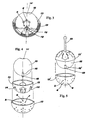
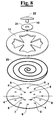
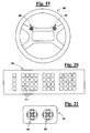
- a matrix configuration according to the invention can have, for example, a cloverleaf shape, with a central rest zone O and four working zones A, B, C, D, arranged radially, in a star rays arrangement, with respect to said central zone O.
- an activation member is located, indicated as 10.
- the working zones A, B, C, D are alike and for each zone (only the sensors of the zone A are numbered advantageously) three sensors 1, 2 and 3 are arranged in the passageway towards each radial zone, and belonging to a first group of sensors.
- In each radial zone other five sensors are provided, distributed at the boundary, as better described hereinafter, and defined by the reference numbers 4, 5, 6, 7 and 8, which belong to a second group of sensors.
- activation member is referred to, as well as “sensor”, being it clear that with the first term the device indicated as 10 is defined, which is a movable element associated to a key or push button, and with the second term an element indicated as 1 up to 8 is defined, which are fixed elements, adapted to measure the presence or the contact of the activation member.
- activation member and respectively “sensor” must not therefore be interpreted narrowly, or in a limitative may, but only as an exemplary way to define two opposite elements that, when they are in coincidence or in close proximity with each other, they are capable to emit a coded signal, specific for each of said sensors and/or of the matrix field that is respectively associated to them.
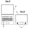
- the activation member 10 is associated to a selection key, here not shown but visible for example in figure 8 and indicated with 22, which is located at the central zone O and is manoeuvrable by the operator.
- This element here and hereinafter called simply as “selection key”
- selection key may have a desired configuration adapted to move the activation member 10 to it associated with respect to the fixed sensors from 1 to 8; such a configuration can be a push button, an actuating stick of the type used for controlling a "palm top”, or a pin or button or lever of manoeuvre hinged at the centre, preferably associated to resilient means that, when the lever is operated for displacing the activation member 10 towards the radial zones, and then released, tends to bring it back always towards the centre.
- the selection key When the selection key is operated towards one of the radial zones, firstly it passes at one of the sensors 1, 2 and 3 of the respective zone and, thus activating one of them, which for example can be a contact or a proximity sensor, a microswitch, a Hall effect sensor, a magnetoresistive sensor or a active matrix sensor. Depending on whether this activation affects sensor 1, 2 or 3, a first, or a second, or a third matrix field associated to said zone is correspondingly selected; these matrix fields can be considered “virtual" because each field is determined by the same sensors from 4 to 8 of a specific zone, but considered in a different way by the control unit, responsive to which sensors from 1 to 3 had been pre-selected.
- the selection key when the selection key continues its movement up to one of sensors 4, 5, 6, 7, 8, it activates the selection of one of the characters/symbols associated to the selected sensor and respectively to the first, to the second or to the third matrix field.
- the selection key moves for example towards zone A, it is intentionally brought to slide in the vicinity of one of sensors 1, 2 or 3 of the first group, as desired, for example sensor 2, thus activating matrix field 2.
- the selection key is then brought at one of the five sensors of the second group, which are arranged according to this zone A; for example the sensor chosen is sensor 5, activating as defined above the character corresponding to letter "g"; this character corresponds in fact to sensor 5 of second matrix field 2.
- each zone A, B, C or D three matrix fields correspond and to each of these fields five characters correspond, therefore fifteen characters for each zone, i.e. sixty characters or different symbols in the combination of the four zones.
- this is a simple example and that it is very easy for a skilled person to design a matrix that, instead of having four cloverleaf zones and five sensors for each zone, it has a different number of zones and a different number of sensors for each zone.
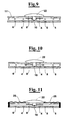
- FIG. 16 An example of this arrangement is given in figures 16 , 17 and 18 .
- figure 16 for each zone A-D two sensors of the first group are provided, indicated as 1 and 2 for zone A, and three sensors of the second group, indicated as 3, 4, 5 for zone A.
- This device with twenty sensors, allows to select up to 24 symbols or characters for each mode of operation of the selection key 10.
- the four zones A-D are four respective quadrants, having common sides.
- This device by means of 68 sensors, allows to select up to 228 symbols or characters for each mode of operation of the selection key 10.
- This solution with adjacent quadrants is very effective since it is possible to put common sensors at the border between two adjacent zones, i.e. the common sides, as in the case of sensors 4 and 8.
- the sensors 4 and 8 are discriminated according to the path followed for the respective zone, recognizing the respective sensor of the first group, 1 or 2 in case of zone A.
- the sensors 4-8 for all the zones and for various exemplary embodiments shown up to here, can be made within the edges of the zone or at the edges same. The same occurs for the gate sensors indicated as 1 and 3, excluded sensor 2 that is located at the centre.
- the transmission of a coded signal from one of the sensors from 1 to 8 takes place not only when the activation member 10 moves in perfect coincidence with one of them; it is enough that the activation member 10 moves close to one of them to select it, at a distance nearer than to the others.
- the motion of the activation member 10 near a desired sensor 1 to 8 provides an electric signal, for example by Hall effect, which is proportional to the overlap of the active surfaces of such sensors. It is not necessary, as already mentioned, that the passage on sensor occurs with high precision, but only the strongest signal, i.e. in proximity to a sensor, higher with respect to the other sensors near it.
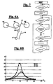
- FIG. 6A This aspect is diagrammatically shown in figures 6A and 6B with reference, for example, to the three sensors 1, 2, 3 that are located, with reference for example to figures 1, 2 or 15 , on the passageway of activation member 10 when it is moved from the central position towards one of zones A, B, C or D, for example zone A.
- the action of the finger of the hand on the selection key, for reaching the different sensors, in particular, sensors 4, 5, 6, 7, 8 located on the contour of each radial zones A, B, C, etc., is carried out in a way assisted by stopping the selection key against the edge of each zone; concerning the sensors of the first group 1, 2, 3 located on the passageway between the central zone or and the radial zones, the movement through them is more intuitive, for example sliding on the edge at the right or the left of the figure, concerning respectively sensors 1 and 3, or running in the centre on sensor 2, when a user is sufficiently trained.
- a reference for guiding the activation member for selecting the sensors of the first group can be provided, such as grooves or ridges.
- the choice of the characters is immediate, for having a quick selection.
- the user can cancel it maintaining the selection key on the same sensor for a longer time, at the end of which the control routine carries out its cancellation and the user can then select a correct character.
- the logic of drive cannot select instantly a character, but it has to wait a confirmation from the user; such a confirmation can be given, for example, with a short pressure on the selection key or, in an easier way, on a short stop of the selection key at the chosen sensor.
- control routine proceeds for example according to the flow-sheet of figure 7 , but it is clear that this diagram is purely exemplary and a skilled person can provide different equivalent softwares.
- this diagram is purely exemplary and a skilled person can provide different equivalent softwares.
- Preselection the activation has been indicated of a sensor of the first group
- selection the activation of a sensor of the second group has been indicated.
- a deleting mode can be provided, for example, as already said, with permanence of the selection key on a respective sensor for a longer time letting the operator to choose then another symbol or character; it will move then to another position of the same zone, if the symbol is along the same path, or it will follow a different path in the same zone, or it will enter different zones according to the above described procedure.
- the control routine is such that when exiting from a zone the coding operations are not affected, unless cancelling the previous pre-selections.
- a single and progressive cancellation is activated.
- the function of cancellation can be achieved by following a succession of a determined sensor of the first group and of one of the second group.
- a pressure of the selection key in the central position, on activation member 10 could cause a commutation of the logic of drive among different programs, to associate then to the different sensors thus achieved functions different from those related to simple transmission of characters, as usual in keyboards of cellular telephones.
- a position sensor could be provided that is lower with respect to all the other (not shown in the figures) so that the resilient means bring back to the centre the activation member and allow the latter to reach the lower sensor and to push the same thus generating a signal that can affect all the keyboard.
- the type of writing is changed, as well as the symbols, which can pass from lower case to upper case, etc.
- FIG 2 shows, very diagrammatically, a first way of operation of the present invention, with the matrix structure formed in a plane 11, actually made up of two coupled plates 11' and 11", of which the upper plate 11' defines a contour that defines zones A, B, C and D and the lower plate 11" has the sensors associated to each zone.
- this plane structure can be used, as selection key, in addition to the slider shown in figures from 8 to 11, also a driving stick (of the type already known in electronic devices like "palm top”), whose tip is caused to slide in the plane of the sensors, guided in part by the support on the protruding contour defining the zones of the matrix.
- the user can work simply causing first the stick to rest at the centre, on the activation member 10, only with the object of activating the matrix, and then causing the tip of the stick to slide on the surface that has the sensors, towards one of the radial zones, causing then it to pass firstly on one of the sensors 1, 2, 3 of the first group of sensors and then bringing it in contact with one of the sensors 4, 5, 6, 7 and 8 of the second group.
- Figures 3 and 4 show instead, always very diagrammatically, a second exemplary embodiment of the present invention, with the matrix structure formed on of a spherical cap.
- the spherical cap comprises a first surface 12, on which the sensors from 1 to 8 are located, and a second surface 13, on which windows 14 are made for delimitation to the areas O, A, B, C and D.
- a ball of control 15 is inserted, having a guiding appendage 16; this appendage, which is capable of moving within the window 14 for being from these guided towards the sensors from 1 to 8, has at its end the active element, i.e. activation member 10, capable of activating the different other sensors, relevant to each zone, as previously shown, located on the surface 12.
- activation member 10 capable of activating the different other sensors, relevant to each zone, as previously shown, located on the surface 12.
- the guiding appendage 16 can be magnetic, arranged with its own axis coincident with the pole axis of the ball and protruding from the spherical surface of a measure which is the same as the thickness of the spherical cap 13 containing the track of control consisting of windows 14.
- a base surface 10 of said appendage 16 is tangential to the inner surface of spherical cap 12, on which the sensors 1 to 8 are located, adapted to be activated according to the logic shown, to calculate the passage and the position of the selection key associated to appendage 16.
- spherical cap notwithstanding the representation of figures from 3 to 5 relates actually to a ball, has to be construed in a a purely exemplifying way: it is in fact straightforward for a skilled person to think to the use of an another desired surface having finite curvature, having a centre or an axis of rotation.
- a recess 15' can be provided, or a protrusion or a ridged or knurled surface, to assist the grip by the user.
- figure 1 can be representative, approximately, also to the projection of a spherical portion 12, 13, seen from the upper pole, in a plane tangential to to the lower ball pole.
- the active element or activation member 10 associated to guiding appendage 16 has then a function equivalent to that of element 10 of figure 1 , put in the tip of the stick used in the exemplary embodiment of figure 2 .
- the ball 15 is operated for example causing it to rotate by friction with the tip of a finger that rests on its upper part: when the ball is thus caused to rotate, the cylindrical appendage 16 equipped with the activation member 10, is moved in turn, sliding firstly on the sensors 1, 2, 3 of the first group and then on the sensors 4 to 8 of the second group, all associated to the ball 12; the motion of activation member 10 near one of the sensors 1 to 8 provides an electric signal in the way already described with reference to figure 1 ,.
- On the ball can be represented, for example, the shape of a cloverleaf with the sensors of the first and second group and its relative function.
- sensors based on magnetic field variation can use other desired techniques, such as the capacity variation, optical techniques, phototransistor arrays, or the properties of conductivity of microtransistors on a polymeric substrate exploiting recent developments of nanotechnologies" of microelectronics or other techniques obvious to the skilled person.
Landscapes
- Engineering & Computer Science (AREA)
- Theoretical Computer Science (AREA)
- General Engineering & Computer Science (AREA)
- Human Computer Interaction (AREA)
- Physics & Mathematics (AREA)
- General Physics & Mathematics (AREA)
- Computer Hardware Design (AREA)
- Input From Keyboards Or The Like (AREA)
- Executing Machine-Instructions (AREA)
- Selective Calling Equipment (AREA)
Applications Claiming Priority (2)
| Application Number | Priority Date | Filing Date | Title |
|---|---|---|---|
| IT000855A ITMI20050855A1 (it) | 2005-05-12 | 2005-05-12 | Dispositivo compatto a matrice ed azionamento a singolo tasto per la codifica e selezione di caratteri e-o scelte multiple e relativa logica di controllo |
| PCT/IB2006/001197 WO2006120543A2 (en) | 2005-05-12 | 2006-05-09 | Device for selection of symbols, such as characters, icons and/or multiple choices |
Publications (2)
| Publication Number | Publication Date |
|---|---|
| EP1880268A2 EP1880268A2 (en) | 2008-01-23 |
| EP1880268B1 true EP1880268B1 (en) | 2011-08-24 |
Family
ID=37396932
Family Applications (1)
| Application Number | Title | Priority Date | Filing Date |
|---|---|---|---|
| EP06755864A Not-in-force EP1880268B1 (en) | 2005-05-12 | 2006-05-09 | Device for selection of symbols, such as characters, icons and/or multiple choices |
Country Status (10)
| Country | Link |
|---|---|
| US (1) | US8274407B2 (enExample) |
| EP (1) | EP1880268B1 (enExample) |
| JP (1) | JP4881374B2 (enExample) |
| KR (1) | KR20080054369A (enExample) |
| CN (1) | CN101218555B (enExample) |
| AT (1) | ATE521933T1 (enExample) |
| CA (1) | CA2608155A1 (enExample) |
| IT (1) | ITMI20050855A1 (enExample) |
| MX (1) | MX2007014123A (enExample) |
| WO (1) | WO2006120543A2 (enExample) |
Families Citing this family (5)
| Publication number | Priority date | Publication date | Assignee | Title |
|---|---|---|---|---|
| EP2123002A4 (en) * | 2007-02-13 | 2012-01-25 | Eui Jin Oh | CHARACTER INPUT DEVICE |
| US9110515B2 (en) * | 2009-08-19 | 2015-08-18 | Nuance Communications, Inc. | Method and apparatus for text input |
| KR101866272B1 (ko) * | 2011-12-15 | 2018-06-12 | 삼성전자주식회사 | 그립 센서를 이용한 사용자 기반의 휴대용 단말기의 장치 및 방법 |
| HUP1500189A2 (en) * | 2015-04-24 | 2016-10-28 | Geza Balint | Process and recording device for recording data electronically |
| CN110612507B (zh) * | 2017-05-26 | 2023-06-09 | 深圳纽迪瑞科技开发有限公司 | 单按键及按键阵列 |
Family Cites Families (8)
| Publication number | Priority date | Publication date | Assignee | Title |
|---|---|---|---|---|
| US5831554A (en) * | 1997-09-08 | 1998-11-03 | Joseph Pollak Corporation | Angular position sensor for pivoted control devices |
| US6448670B1 (en) * | 1998-05-12 | 2002-09-10 | Alps Electric Co., Ltd. | Signal input device |
| JP3191284B2 (ja) * | 1998-06-23 | 2001-07-23 | 日本電気株式会社 | 文字入力装置 |
| US20010048425A1 (en) * | 2000-04-28 | 2001-12-06 | Partridge Gary R. | Device or component for alphanumeric and direction input |
| GB2364208B (en) * | 2000-06-30 | 2004-11-17 | Nokia Mobile Phones Ltd | Improved data input |
| BE1015349A5 (fr) * | 2003-02-06 | 2005-02-01 | Prud Homme Fran Ois | Dispositif a saisies combinatoires et ou directes de textes et de donnees par dactylo-entrainements memotechniques sensitifs et secrets sur des touches a multi-directions. |
| KR100525470B1 (ko) * | 2003-02-14 | 2005-11-23 | 오의진 | 입력키가 손가락의 이동반경 내에 위치되어 있는입력장치와 이를 사용한 명령 입력방법 |
| ATE444515T1 (de) * | 2003-12-23 | 2009-10-15 | Nokia Corp | Verfahren und vorrichtung zur eingabe von daten mit einem achtweg-eingabegerät |
-
2005
- 2005-05-12 IT IT000855A patent/ITMI20050855A1/it unknown
-
2006
- 2006-05-09 EP EP06755864A patent/EP1880268B1/en not_active Not-in-force
- 2006-05-09 US US11/914,333 patent/US8274407B2/en not_active Expired - Fee Related
- 2006-05-09 AT AT06755864T patent/ATE521933T1/de not_active IP Right Cessation
- 2006-05-09 MX MX2007014123A patent/MX2007014123A/es active IP Right Grant
- 2006-05-09 CN CN2006800211932A patent/CN101218555B/zh not_active Expired - Fee Related
- 2006-05-09 WO PCT/IB2006/001197 patent/WO2006120543A2/en not_active Ceased
- 2006-05-09 KR KR1020077028993A patent/KR20080054369A/ko not_active Abandoned
- 2006-05-09 CA CA002608155A patent/CA2608155A1/en not_active Abandoned
- 2006-05-09 JP JP2008510661A patent/JP4881374B2/ja not_active Expired - Fee Related
Also Published As
| Publication number | Publication date |
|---|---|
| CN101218555B (zh) | 2010-06-30 |
| US8274407B2 (en) | 2012-09-25 |
| EP1880268A2 (en) | 2008-01-23 |
| ITMI20050855A1 (it) | 2006-11-13 |
| WO2006120543A3 (en) | 2007-03-29 |
| CN101218555A (zh) | 2008-07-09 |
| KR20080054369A (ko) | 2008-06-17 |
| ATE521933T1 (de) | 2011-09-15 |
| US20080211695A1 (en) | 2008-09-04 |
| MX2007014123A (es) | 2008-03-24 |
| CA2608155A1 (en) | 2006-11-16 |
| WO2006120543A2 (en) | 2006-11-16 |
| JP4881374B2 (ja) | 2012-02-22 |
| JP2008541258A (ja) | 2008-11-20 |
Similar Documents
| Publication | Publication Date | Title |
|---|---|---|
| CN100370401C (zh) | 特别用于机动车的多媒体系统的操作部件 | |
| KR101010500B1 (ko) | 회전 및 누름식 버튼 컨트롤러 | |
| US6166721A (en) | Mouse as computer input device having additional mechanism for controlling additional function such as scrolling | |
| KR101128803B1 (ko) | 이동 단말기, 및 터치 패널을 구비한 이동 단말기에서의입력신호 처리방법 | |
| CN101965266B (zh) | 能够接受文本输入的无线手持设备以及用于在无线手持设备上输入文本的方法 | |
| US5543592A (en) | Multimode manipulator | |
| US5164712A (en) | X-Y direction input device | |
| KR101773032B1 (ko) | 다기능 복합 입력 장치 | |
| KR20080010266A (ko) | 문자입력장치 | |
| EP1880268B1 (en) | Device for selection of symbols, such as characters, icons and/or multiple choices | |
| JP4415689B2 (ja) | ステアリング | |
| KR100466874B1 (ko) | 휴대단말기용 입력장치 및 그 입력방법 | |
| KR20090006718A (ko) | 손가락의 동작감지를 이용한 데이터입력장치 | |
| KR100488971B1 (ko) | 텔레메틱스 단말기에서의 문자 입력 장치 및 방법 | |
| JP4617216B2 (ja) | 多方向入力装置 | |
| US20060279529A1 (en) | Input device | |
| KR100655963B1 (ko) | 이동 통신 단말기에 제공되는 회전식 입력 버튼 | |
| JP6788789B2 (ja) | 変速機の入力装置 | |
| JP4617217B2 (ja) | 多方向入力装置 | |
| JP2002032190A (ja) | ポインティングデバイス | |
| KR200187254Y1 (ko) | 퍼스널 컴퓨터의 마우스 | |
| US20090289816A1 (en) | One-handed computer input device comprising finger array input controls | |
| KR20080076860A (ko) | 데이터 입력장치 | |
| KR20080021317A (ko) | 문자입력장치 및 문자입력방법 | |
| KR20080099768A (ko) | 데이터입력장치 |
Legal Events
| Date | Code | Title | Description |
|---|---|---|---|
| PUAI | Public reference made under article 153(3) epc to a published international application that has entered the european phase |
Free format text: ORIGINAL CODE: 0009012 |
|
| 17P | Request for examination filed |
Effective date: 20071116 |
|
| AK | Designated contracting states |
Kind code of ref document: A2 Designated state(s): AT BE BG CH CY CZ DE DK EE ES FI FR GB GR HU IE IS IT LI LT LU LV MC NL PL PT RO SE SI SK TR |
|
| RAP1 | Party data changed (applicant data changed or rights of an application transferred) |
Owner name: MATRIX PROJECTS LLC |
|
| DAX | Request for extension of the european patent (deleted) | ||
| 17Q | First examination report despatched |
Effective date: 20090525 |
|
| GRAP | Despatch of communication of intention to grant a patent |
Free format text: ORIGINAL CODE: EPIDOSNIGR1 |
|
| GRAS | Grant fee paid |
Free format text: ORIGINAL CODE: EPIDOSNIGR3 |
|
| GRAA | (expected) grant |
Free format text: ORIGINAL CODE: 0009210 |
|
| AK | Designated contracting states |
Kind code of ref document: B1 Designated state(s): AT BE BG CH CY CZ DE DK EE ES FI FR GB GR HU IE IS IT LI LT LU LV MC NL PL PT RO SE SI SK TR |
|
| REG | Reference to a national code |
Ref country code: GB Ref legal event code: FG4D |
|
| REG | Reference to a national code |
Ref country code: CH Ref legal event code: EP |
|
| REG | Reference to a national code |
Ref country code: IE Ref legal event code: FG4D |
|
| REG | Reference to a national code |
Ref country code: DE Ref legal event code: R096 Ref document number: 602006024029 Country of ref document: DE Effective date: 20111124 |
|
| REG | Reference to a national code |
Ref country code: NL Ref legal event code: VDEP Effective date: 20110824 |
|
| LTIE | Lt: invalidation of european patent or patent extension |
Effective date: 20110824 |
|
| PG25 | Lapsed in a contracting state [announced via postgrant information from national office to epo] |
Ref country code: IS Free format text: LAPSE BECAUSE OF FAILURE TO SUBMIT A TRANSLATION OF THE DESCRIPTION OR TO PAY THE FEE WITHIN THE PRESCRIBED TIME-LIMIT Effective date: 20111224 Ref country code: NL Free format text: LAPSE BECAUSE OF FAILURE TO SUBMIT A TRANSLATION OF THE DESCRIPTION OR TO PAY THE FEE WITHIN THE PRESCRIBED TIME-LIMIT Effective date: 20110824 Ref country code: PT Free format text: LAPSE BECAUSE OF FAILURE TO SUBMIT A TRANSLATION OF THE DESCRIPTION OR TO PAY THE FEE WITHIN THE PRESCRIBED TIME-LIMIT Effective date: 20111226 Ref country code: SE Free format text: LAPSE BECAUSE OF FAILURE TO SUBMIT A TRANSLATION OF THE DESCRIPTION OR TO PAY THE FEE WITHIN THE PRESCRIBED TIME-LIMIT Effective date: 20110824 Ref country code: LT Free format text: LAPSE BECAUSE OF FAILURE TO SUBMIT A TRANSLATION OF THE DESCRIPTION OR TO PAY THE FEE WITHIN THE PRESCRIBED TIME-LIMIT Effective date: 20110824 Ref country code: FI Free format text: LAPSE BECAUSE OF FAILURE TO SUBMIT A TRANSLATION OF THE DESCRIPTION OR TO PAY THE FEE WITHIN THE PRESCRIBED TIME-LIMIT Effective date: 20110824 |
|
| REG | Reference to a national code |
Ref country code: AT Ref legal event code: MK05 Ref document number: 521933 Country of ref document: AT Kind code of ref document: T Effective date: 20110824 |
|
| PG25 | Lapsed in a contracting state [announced via postgrant information from national office to epo] |
Ref country code: SI Free format text: LAPSE BECAUSE OF FAILURE TO SUBMIT A TRANSLATION OF THE DESCRIPTION OR TO PAY THE FEE WITHIN THE PRESCRIBED TIME-LIMIT Effective date: 20110824 Ref country code: PL Free format text: LAPSE BECAUSE OF FAILURE TO SUBMIT A TRANSLATION OF THE DESCRIPTION OR TO PAY THE FEE WITHIN THE PRESCRIBED TIME-LIMIT Effective date: 20110824 Ref country code: CY Free format text: LAPSE BECAUSE OF FAILURE TO SUBMIT A TRANSLATION OF THE DESCRIPTION OR TO PAY THE FEE WITHIN THE PRESCRIBED TIME-LIMIT Effective date: 20110824 Ref country code: AT Free format text: LAPSE BECAUSE OF FAILURE TO SUBMIT A TRANSLATION OF THE DESCRIPTION OR TO PAY THE FEE WITHIN THE PRESCRIBED TIME-LIMIT Effective date: 20110824 Ref country code: LV Free format text: LAPSE BECAUSE OF FAILURE TO SUBMIT A TRANSLATION OF THE DESCRIPTION OR TO PAY THE FEE WITHIN THE PRESCRIBED TIME-LIMIT Effective date: 20110824 Ref country code: GR Free format text: LAPSE BECAUSE OF FAILURE TO SUBMIT A TRANSLATION OF THE DESCRIPTION OR TO PAY THE FEE WITHIN THE PRESCRIBED TIME-LIMIT Effective date: 20111125 |
|
| PG25 | Lapsed in a contracting state [announced via postgrant information from national office to epo] |
Ref country code: BE Free format text: LAPSE BECAUSE OF FAILURE TO SUBMIT A TRANSLATION OF THE DESCRIPTION OR TO PAY THE FEE WITHIN THE PRESCRIBED TIME-LIMIT Effective date: 20110824 |
|
| PG25 | Lapsed in a contracting state [announced via postgrant information from national office to epo] |
Ref country code: SK Free format text: LAPSE BECAUSE OF FAILURE TO SUBMIT A TRANSLATION OF THE DESCRIPTION OR TO PAY THE FEE WITHIN THE PRESCRIBED TIME-LIMIT Effective date: 20110824 Ref country code: CZ Free format text: LAPSE BECAUSE OF FAILURE TO SUBMIT A TRANSLATION OF THE DESCRIPTION OR TO PAY THE FEE WITHIN THE PRESCRIBED TIME-LIMIT Effective date: 20110824 |
|
| PG25 | Lapsed in a contracting state [announced via postgrant information from national office to epo] |
Ref country code: EE Free format text: LAPSE BECAUSE OF FAILURE TO SUBMIT A TRANSLATION OF THE DESCRIPTION OR TO PAY THE FEE WITHIN THE PRESCRIBED TIME-LIMIT Effective date: 20110824 Ref country code: RO Free format text: LAPSE BECAUSE OF FAILURE TO SUBMIT A TRANSLATION OF THE DESCRIPTION OR TO PAY THE FEE WITHIN THE PRESCRIBED TIME-LIMIT Effective date: 20110824 |
|
| PG25 | Lapsed in a contracting state [announced via postgrant information from national office to epo] |
Ref country code: DK Free format text: LAPSE BECAUSE OF FAILURE TO SUBMIT A TRANSLATION OF THE DESCRIPTION OR TO PAY THE FEE WITHIN THE PRESCRIBED TIME-LIMIT Effective date: 20110824 |
|
| PLBE | No opposition filed within time limit |
Free format text: ORIGINAL CODE: 0009261 |
|
| STAA | Information on the status of an ep patent application or granted ep patent |
Free format text: STATUS: NO OPPOSITION FILED WITHIN TIME LIMIT |
|
| 26N | No opposition filed |
Effective date: 20120525 |
|
| REG | Reference to a national code |
Ref country code: DE Ref legal event code: R097 Ref document number: 602006024029 Country of ref document: DE Effective date: 20120525 |
|
| PG25 | Lapsed in a contracting state [announced via postgrant information from national office to epo] |
Ref country code: MC Free format text: LAPSE BECAUSE OF NON-PAYMENT OF DUE FEES Effective date: 20120531 |
|
| REG | Reference to a national code |
Ref country code: CH Ref legal event code: PL |
|
| PG25 | Lapsed in a contracting state [announced via postgrant information from national office to epo] |
Ref country code: CH Free format text: LAPSE BECAUSE OF NON-PAYMENT OF DUE FEES Effective date: 20120531 Ref country code: LI Free format text: LAPSE BECAUSE OF NON-PAYMENT OF DUE FEES Effective date: 20120531 |
|
| REG | Reference to a national code |
Ref country code: IE Ref legal event code: MM4A |
|
| PG25 | Lapsed in a contracting state [announced via postgrant information from national office to epo] |
Ref country code: ES Free format text: LAPSE BECAUSE OF FAILURE TO SUBMIT A TRANSLATION OF THE DESCRIPTION OR TO PAY THE FEE WITHIN THE PRESCRIBED TIME-LIMIT Effective date: 20111205 Ref country code: IE Free format text: LAPSE BECAUSE OF NON-PAYMENT OF DUE FEES Effective date: 20120509 |
|
| PGFP | Annual fee paid to national office [announced via postgrant information from national office to epo] |
Ref country code: GB Payment date: 20130328 Year of fee payment: 8 |
|
| PG25 | Lapsed in a contracting state [announced via postgrant information from national office to epo] |
Ref country code: BG Free format text: LAPSE BECAUSE OF FAILURE TO SUBMIT A TRANSLATION OF THE DESCRIPTION OR TO PAY THE FEE WITHIN THE PRESCRIBED TIME-LIMIT Effective date: 20111124 |
|
| PGFP | Annual fee paid to national office [announced via postgrant information from national office to epo] |
Ref country code: IT Payment date: 20130410 Year of fee payment: 8 Ref country code: FR Payment date: 20130419 Year of fee payment: 8 |
|
| PGFP | Annual fee paid to national office [announced via postgrant information from national office to epo] |
Ref country code: DE Payment date: 20130710 Year of fee payment: 8 |
|
| PG25 | Lapsed in a contracting state [announced via postgrant information from national office to epo] |
Ref country code: TR Free format text: LAPSE BECAUSE OF FAILURE TO SUBMIT A TRANSLATION OF THE DESCRIPTION OR TO PAY THE FEE WITHIN THE PRESCRIBED TIME-LIMIT Effective date: 20110824 |
|
| PG25 | Lapsed in a contracting state [announced via postgrant information from national office to epo] |
Ref country code: LU Free format text: LAPSE BECAUSE OF NON-PAYMENT OF DUE FEES Effective date: 20120509 |
|
| PG25 | Lapsed in a contracting state [announced via postgrant information from national office to epo] |
Ref country code: HU Free format text: LAPSE BECAUSE OF FAILURE TO SUBMIT A TRANSLATION OF THE DESCRIPTION OR TO PAY THE FEE WITHIN THE PRESCRIBED TIME-LIMIT Effective date: 20060509 |
|
| REG | Reference to a national code |
Ref country code: DE Ref legal event code: R119 Ref document number: 602006024029 Country of ref document: DE |
|
| GBPC | Gb: european patent ceased through non-payment of renewal fee |
Effective date: 20140509 |
|
| REG | Reference to a national code |
Ref country code: FR Ref legal event code: ST Effective date: 20150130 |
|
| REG | Reference to a national code |
Ref country code: DE Ref legal event code: R119 Ref document number: 602006024029 Country of ref document: DE Effective date: 20141202 |
|
| PG25 | Lapsed in a contracting state [announced via postgrant information from national office to epo] |
Ref country code: DE Free format text: LAPSE BECAUSE OF NON-PAYMENT OF DUE FEES Effective date: 20141202 Ref country code: IT Free format text: LAPSE BECAUSE OF NON-PAYMENT OF DUE FEES Effective date: 20140509 |
|
| PG25 | Lapsed in a contracting state [announced via postgrant information from national office to epo] |
Ref country code: GB Free format text: LAPSE BECAUSE OF NON-PAYMENT OF DUE FEES Effective date: 20140509 Ref country code: FR Free format text: LAPSE BECAUSE OF NON-PAYMENT OF DUE FEES Effective date: 20140602 |