EP1877124B1 - Neurovascular intervention device - Google Patents
Neurovascular intervention device Download PDFInfo
- Publication number
- EP1877124B1 EP1877124B1 EP06750801A EP06750801A EP1877124B1 EP 1877124 B1 EP1877124 B1 EP 1877124B1 EP 06750801 A EP06750801 A EP 06750801A EP 06750801 A EP06750801 A EP 06750801A EP 1877124 B1 EP1877124 B1 EP 1877124B1
- Authority
- EP
- European Patent Office
- Prior art keywords
- imaging
- sheath
- wire
- microcatheter
- treatment device
- Prior art date
- Legal status (The legal status is an assumption and is not a legal conclusion. Google has not performed a legal analysis and makes no representation as to the accuracy of the status listed.)
- Not-in-force
Links
- 238000003384 imaging method Methods 0.000 claims abstract description 70
- 238000011282 treatment Methods 0.000 claims abstract description 42
- 230000003073 embolic effect Effects 0.000 claims abstract description 6
- 238000000034 method Methods 0.000 claims description 6
- 229940079593 drug Drugs 0.000 claims description 3
- 239000003814 drug Substances 0.000 claims description 3
- HLXZNVUGXRDIFK-UHFFFAOYSA-N nickel titanium Chemical compound [Ti].[Ti].[Ti].[Ti].[Ti].[Ti].[Ti].[Ti].[Ti].[Ti].[Ti].[Ni].[Ni].[Ni].[Ni].[Ni].[Ni].[Ni].[Ni].[Ni].[Ni].[Ni].[Ni].[Ni].[Ni] HLXZNVUGXRDIFK-UHFFFAOYSA-N 0.000 claims description 2
- 229910001000 nickel titanium Inorganic materials 0.000 claims description 2
- 239000003527 fibrinolytic agent Substances 0.000 abstract description 3
- 229960000103 thrombolytic agent Drugs 0.000 abstract description 3
- 239000004593 Epoxy Substances 0.000 description 11
- 206010002329 Aneurysm Diseases 0.000 description 7
- BQCADISMDOOEFD-UHFFFAOYSA-N Silver Chemical compound [Ag] BQCADISMDOOEFD-UHFFFAOYSA-N 0.000 description 6
- 239000000463 material Substances 0.000 description 6
- 229910052709 silver Inorganic materials 0.000 description 6
- 239000004332 silver Substances 0.000 description 6
- 238000012014 optical coherence tomography Methods 0.000 description 5
- 208000005189 Embolism Diseases 0.000 description 4
- 239000004020 conductor Substances 0.000 description 4
- 208000007536 Thrombosis Diseases 0.000 description 3
- 239000012530 fluid Substances 0.000 description 3
- 229920000642 polymer Polymers 0.000 description 3
- 229910000831 Steel Inorganic materials 0.000 description 2
- 208000006011 Stroke Diseases 0.000 description 2
- 210000001367 artery Anatomy 0.000 description 2
- 239000011248 coating agent Substances 0.000 description 2
- 238000000576 coating method Methods 0.000 description 2
- 238000001802 infusion Methods 0.000 description 2
- 239000010959 steel Substances 0.000 description 2
- HTTJABKRGRZYRN-UHFFFAOYSA-N Heparin Chemical compound OC1C(NC(=O)C)C(O)OC(COS(O)(=O)=O)C1OC1C(OS(O)(=O)=O)C(O)C(OC2C(C(OS(O)(=O)=O)C(OC3C(C(O)C(O)C(O3)C(O)=O)OS(O)(=O)=O)C(CO)O2)NS(O)(=O)=O)C(C(O)=O)O1 HTTJABKRGRZYRN-UHFFFAOYSA-N 0.000 description 1
- FAPWRFPIFSIZLT-UHFFFAOYSA-M Sodium chloride Chemical compound [Na+].[Cl-] FAPWRFPIFSIZLT-UHFFFAOYSA-M 0.000 description 1
- 230000002745 absorbent Effects 0.000 description 1
- 239000002250 absorbent Substances 0.000 description 1
- 238000011256 aggressive treatment Methods 0.000 description 1
- 230000003466 anti-cipated effect Effects 0.000 description 1
- 230000009286 beneficial effect Effects 0.000 description 1
- 239000008280 blood Substances 0.000 description 1
- 210000004369 blood Anatomy 0.000 description 1
- 230000036772 blood pressure Effects 0.000 description 1
- 210000001627 cerebral artery Anatomy 0.000 description 1
- 239000003795 chemical substances by application Substances 0.000 description 1
- 238000004891 communication Methods 0.000 description 1
- 239000013078 crystal Substances 0.000 description 1
- 238000003745 diagnosis Methods 0.000 description 1
- 238000002059 diagnostic imaging Methods 0.000 description 1
- 238000010586 diagram Methods 0.000 description 1
- 230000002526 effect on cardiovascular system Effects 0.000 description 1
- 239000000835 fiber Substances 0.000 description 1
- 229960002897 heparin Drugs 0.000 description 1
- 229920000669 heparin Polymers 0.000 description 1
- 239000011810 insulating material Substances 0.000 description 1
- 238000002608 intravascular ultrasound Methods 0.000 description 1
- 229910052751 metal Inorganic materials 0.000 description 1
- 239000002184 metal Substances 0.000 description 1
- 238000002324 minimally invasive surgery Methods 0.000 description 1
- 238000012986 modification Methods 0.000 description 1
- 230000004048 modification Effects 0.000 description 1
- 238000011228 multimodal treatment Methods 0.000 description 1
- 230000007935 neutral effect Effects 0.000 description 1
- 230000003287 optical effect Effects 0.000 description 1
- 239000002245 particle Substances 0.000 description 1
- 239000008177 pharmaceutical agent Substances 0.000 description 1
- 230000035945 sensitivity Effects 0.000 description 1
- 239000011780 sodium chloride Substances 0.000 description 1
- 229910001220 stainless steel Inorganic materials 0.000 description 1
- 239000010935 stainless steel Substances 0.000 description 1
- 239000000126 substance Substances 0.000 description 1
- 239000000758 substrate Substances 0.000 description 1
- WFKWXMTUELFFGS-UHFFFAOYSA-N tungsten Chemical compound [W] WFKWXMTUELFFGS-UHFFFAOYSA-N 0.000 description 1
- 229910052721 tungsten Inorganic materials 0.000 description 1
- 239000010937 tungsten Substances 0.000 description 1
- 238000012285 ultrasound imaging Methods 0.000 description 1
- 230000002792 vascular Effects 0.000 description 1
- 231100000216 vascular lesion Toxicity 0.000 description 1
- 210000005166 vasculature Anatomy 0.000 description 1
Images
Classifications
-
- A—HUMAN NECESSITIES
- A61—MEDICAL OR VETERINARY SCIENCE; HYGIENE
- A61B—DIAGNOSIS; SURGERY; IDENTIFICATION
- A61B8/00—Diagnosis using ultrasonic, sonic or infrasonic waves
- A61B8/12—Diagnosis using ultrasonic, sonic or infrasonic waves in body cavities or body tracts, e.g. by using catheters
-
- A—HUMAN NECESSITIES
- A61—MEDICAL OR VETERINARY SCIENCE; HYGIENE
- A61B—DIAGNOSIS; SURGERY; IDENTIFICATION
- A61B8/00—Diagnosis using ultrasonic, sonic or infrasonic waves
- A61B8/44—Constructional features of the ultrasonic, sonic or infrasonic diagnostic device
- A61B8/4444—Constructional features of the ultrasonic, sonic or infrasonic diagnostic device related to the probe
- A61B8/445—Details of catheter construction
-
- A—HUMAN NECESSITIES
- A61—MEDICAL OR VETERINARY SCIENCE; HYGIENE
- A61M—DEVICES FOR INTRODUCING MEDIA INTO, OR ONTO, THE BODY; DEVICES FOR TRANSDUCING BODY MEDIA OR FOR TAKING MEDIA FROM THE BODY; DEVICES FOR PRODUCING OR ENDING SLEEP OR STUPOR
- A61M25/00—Catheters; Hollow probes
- A61M25/0021—Catheters; Hollow probes characterised by the form of the tubing
- A61M25/0023—Catheters; Hollow probes characterised by the form of the tubing by the form of the lumen, e.g. cross-section, variable diameter
- A61M25/0026—Multi-lumen catheters with stationary elements
- A61M2025/0037—Multi-lumen catheters with stationary elements characterized by lumina being arranged side-by-side
-
- A—HUMAN NECESSITIES
- A61—MEDICAL OR VETERINARY SCIENCE; HYGIENE
- A61M—DEVICES FOR INTRODUCING MEDIA INTO, OR ONTO, THE BODY; DEVICES FOR TRANSDUCING BODY MEDIA OR FOR TAKING MEDIA FROM THE BODY; DEVICES FOR PRODUCING OR ENDING SLEEP OR STUPOR
- A61M25/00—Catheters; Hollow probes
- A61M25/0021—Catheters; Hollow probes characterised by the form of the tubing
- A61M2025/0042—Microcatheters, cannula or the like having outside diameters around 1 mm or less
-
- A—HUMAN NECESSITIES
- A61—MEDICAL OR VETERINARY SCIENCE; HYGIENE
- A61M—DEVICES FOR INTRODUCING MEDIA INTO, OR ONTO, THE BODY; DEVICES FOR TRANSDUCING BODY MEDIA OR FOR TAKING MEDIA FROM THE BODY; DEVICES FOR PRODUCING OR ENDING SLEEP OR STUPOR
- A61M25/00—Catheters; Hollow probes
- A61M25/01—Introducing, guiding, advancing, emplacing or holding catheters
- A61M25/06—Body-piercing guide needles or the like
- A61M25/0662—Guide tubes
- A61M2025/0681—Systems with catheter and outer tubing, e.g. sheath, sleeve or guide tube
Definitions
- the field of the invention relates to medical devices, and more particularly to an neurovascular intervention device.
- Intraluminal, intracavity, intravascular, and intracardiac treatments and diagnosis of medical conditions Utilizing minimally invasive procedures are effective tools in many areas of medical practice. These procedures are typically performed using diagnostic and interventional catheters that are inserted percutaneously into the arterial network and traversed through the vascular system to the site of interest
- the diagnostic catheter may have imaging capability, typically an ultrasound imaging device, which is used to locate and diagnose a diseased portion of the body, such as a stenosed region of an artery.
- imaging capability typically an ultrasound imaging device, which is used to locate and diagnose a diseased portion of the body, such as a stenosed region of an artery.
- U.S. Patent No. 5,368,035, issued to Hamm et al. describes a catheter having an intravascular ultrasound imaging transducer.
- US-A-5, 637, 086 discloses a micro occlusion balloon catheter comprising an elongate member having a proximal and a distal end and a first and second lumen connected to the proximal end.
- the first lumen communicates with an occlusion balloon located at the distal end of the elongate member.
- the second lumen extends the entire length of the elongate member and allows for the placement of the catheter over a guidewire.
- the second lumen communicates with infusion opening located distal to the occlusion balloon.
- There is also disclosed a further arrangement comprising a third lumen connected to the proximal end of the elongate member.
- the third lumen may communicate with an infusion port located either proximally or distally to the occlusion balloon.
- the device includes an outer delivery catheter, an inner delivery catheter, and a guidewire.
- the catheter is designed to pass through the inner lumen of the outer delivery catheter
- the guidewire is designed to pass through the inner lumen of the inner delivery catheter.
- a stent may be loaded inside the outer delivery catheter, with the distal tip of the inner delivery catheter abutting against the proximal end of the self-expanding stent, for pushing the stent distally through the outer delivery catheter.
- EP-A-0, 993, 837 discloses a microbore catheter with a velocity reducing chamber for delivering a pharmaceutical agent or other fluids.
- the internal diameter of the chamber rapidly expands in a transitional region between a proximal portion of the catheter which has a very small or micro internal diameter and a distal portion of the catheter.
- the expanding internal diameter causes the velocity of fluid being delivered to decrease prior to its ejection through a distal opening.
- a fluid delivery system comprising a stylet lumen separate from the delivery lumen. Separate stylet and delivery lumens permit these different portions of the catheter to be independently constructed to maximize the suitability of each lumen for its intended purpose.
- intravascular imaging method for the neurovasculature.
- the procedure steps for coronary interventions serve as baseline.
- the use of the imaging device alternates with the use of the treatment device, i.e., a clinician would insert the imaging device to diagnose the area of interest, and then remove the imaging device to insert the appropriate treatment device.
- a clinician would insert the imaging device to diagnose the area of interest, and then remove the imaging device to insert the appropriate treatment device.
- Applied to the neurovascular system this may be particularly undesirable due to time considerations in the treatment of strokes and/or intravascular aneurysms.
- embolus may come in two forms, hard plaque or soft thrombus, and different treatments may be used for each.
- soft thrombus drug treatment may be preferred, since it is a more conservative treatment, but such a treatment may be ineffective for hard plaque, which may require more aggressive treatments such as stent placement
- the ability to make a quick assessment benefits the patient by receiving the most applicable intervention as soon as possible.
- an aneurysm In the case of an aneurysm, the ability to characterize the aneurysm acourately is very important, particularly for embolic coiling procedures.
- the diameter of the neck of the aneurysm, the diameter of the aneurysm itself, the density of the sac thrombus, and the patency of the parent artery are all important items of data when planning intervention.
- the ability to determine and/or confirm these items of data real time may provide a factor of safety when planning the required intervention.
- the embolic coils originally chosen for treatment based on angiograms may have to be modified based on findings that the aneurysm neck is larger or smaller than anticipated. Accordingly, an improved intravascular intervention device would be desirable.
- an intravascular intervention device comprising: a microcatheter configured to fit in a patient's neurovasculature and comprising a sheath; an imaging wire received within the sheath of the microcatheter, the imaging wire comprising an imaging transducer assembly configured to image the neurovasculature; and a treatment device received within the sheath of the microcatheter, the treatment device being adapted to apply treatment to the neurovasculature, the sheath of the microcatheter being configured to receive both the imaging wire and the treatment device simultaneously and both the imaging wire and the treatment device being capable of being advanced with respect to the sheath.
- the treatment device is configured to perform intravascular intervention.
- the treatment device may be configured to deliver a stent, an embolic coil and/or a thrombolytic agent.
- the intravascular intervention device may image the area of interest while performing the intravascular intervention, thus allowing imaging to take place in real time.
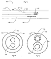
- a microcatheter 100 is shown.
- the microcatheter 100 is constructed to allow navigation into cerebral arteries.
- Such a microcatheter 100 has a size range of up to 0.6858 mm (0.027 inches).
- An example.of such a microcatheter is described in U.S. Patent No. 4, 739, 768 to Engelson .
- the microcatheter 100 includes an outer sheath 110 having a lumen that is capable of receiving an imaging wire 120 and a treatment device 150.
- the microcatheter 100 may utilize a guidewire (not shown) to facilitate in advancing the microcatheter 100 to the area of interest.
- both the imaging wire 120 and the treatment device 150 may be capable of being advanced beyond the distal end of the sheath 110 of the microcatheter 100.
- Fig. 1b which shows a cross-section of a microcatheter 100
- the microcatheter 100 may receive the imaging wire 120 and the treatment device 150 via a single lumen 103.
- Fig. 1c which shows a cross-section of an alternative microcatheter 100
- the microcatheter 100 may receive the imaging wire 120 and the treatment device 150 through a first lumen 104 and a second lumen 102 respectively.
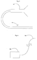
- the imaging wire 120 includes a sheath 121, preferably braided polymer, that is coupled with a floppy tip 124 at the distal end of the sheath 121.
- the sheath 121 includes a lumen that receives an imaging transducer assembly 130 shown in Fig. 2a .
- the imaging wire sheath 121 may be coated with a lubricious coating that enables improved movement within a vessel.
- the imaging sheath 121 preferably includes a puncture hole 122 towards the distal portion of the imaging wire 120, which allows blood pressure to fill the cavity around the imaging element 130 to improve imaging.
- the sheath braid may discontinue for a particular amount of length, thus allowing the imaging transducer to acquire an image with reduced interference.
- the sheath 121 may be withdrawn completely after reaching the desired position, thus leaving the imaging transducer assembly 130 and the floppy tip 124 exposed to the area of interest.
- it may be desirable to coat the assembly 130 with a lubricious and/or thrombolytic agent, such as heparin.
- the sheath 121 may be a thick walled hypotube or partially hollowed rod to allow attachment of the floppy tip 124 and passage of the imaging transducer assembly 130.
- the sheath 121 may include conductive traces that allow the imaging transducer assembly 130 to be electrically coupled with a proximal connector 200 (shown in Fig. 3 ).
- a thin coating of insulating material may protect the conductive traces.
- the floppy tip 124 may be composed of a layered coil atop a cylindrical wire that is flattened into a ribbon under the coil. Further, the floppy tip 124 may have a proximally extended axial section over which the imaging transducer 130 may translate (not shown).
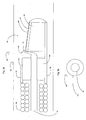
- the imaging transducer 130 includes a coaxial cable 132, having a center conductor wire 136 and an outer shield wire 134, shown in Fig. 2b .
- a conductive wire having a diameter of approximately 500 microns, is wrapped around the coaxial cable 132, forming a coil, which functions as a drive shaft 138.
- the wire may be a laser cut Nitinol tube, which allows for torquability and flexibility.
- the drive shaft 138 may be composed of coaxial cables wound such that the cables are kept separated, via individual shielding or additional wire, while surrounding a neutral core. Further, the drive shaft 138 may be pre-tensioned.
- a stainless steel housing 140 Connected to the distal end of the drive shaft 138 is a stainless steel housing 140, which serves to reinforce the structure of the imaging transducer assembly 130.
- a silver epoxy 142 Surrounding the coaxial cable 132, within the housing 140 is a silver epoxy 142, a conductive material.
- the housing 140 is electrically coupled to the shield wire 134 of the coaxial cable 132 via the epoxy 142.
- an insulating substance e.g., a non-conductive epoxy 144.
- the drive shaft 138 may be printed with one or more conductive traces that allow communication between the imaging transducer 130 and a proximal connector 200 (shown in Fig. 3 ), which allows the imaging transducer 130 to connect to external circuitry 300 that processes signals, such as imaging and navigational signals, from the imaging transducer 130, such circuits being well known (shown in Fig. 4 ).
- the drive shaft 138 may be composed of an extruded polymer reinforced with a polymer/fiber/metal braid with the coaxial cable 132 extruded within the walls (not shown).
- a layer of piezoelectric crystal (“PZT") 147 On the distal end of the non-conductive epoxy 144 is a layer of piezoelectric crystal ("PZT") 147, "sandwiched" between a conductive acoustic lens 146 and a conductive backing material 148, formed from an acoustically absorbent material (e.g., an epoxy substrate having tungsten particles).
- the acoustic lens 146 is electrically coupled with the center conductor wire 136 of the coaxial cable 132 via a connector 145 that is insulated from the silver epoxy 142 and the backing material 148 by the non-conductive epoxy 144.
- the acoustic lens 146 may be non-circular and/or have a convex surface.
- the backing material 148 is connected to the steel housing 140.
- the imaging transducer assembly 130 may be surrounded by a sonolucent media.
- the sonolucent media may be saline.
- the sheath 121 of the imaging wire 120 may include a puncture hole 122 to allow blood to surround the imaging transducer assembly 130 as well.
- the imaging transducer assembly 130 may be translatable relative to the floppy tip 124. Further, the floppy tip 124 may be detachable, thereby exposing the imaging transducer assembly 130.
- the PZT layer 147 is electrically excited by both the backing material 148 and the acoustic lens 146.
- the backing material 148 receives its charge from the shield wire 134 of the coaxial cable 132 via the silver epoxy 142 and the steel housing 140, and the acoustic lens 146, which may also be silver epoxy, receives its charge from the center conductor wire 136 of the coaxial cable 132 via the connector 145, which may be silver epoxy as well.
- transducer 130 is replaced by a phased array as disclosed in Griffith et al., U.S. Patent No. 4,841,977 .
- other imaging devices may be used, instead of, or in addition to imaging transducers, such as light based apparatuses for obtaining images through optical coherence tomography (OCT).
- OCT optical coherence tomography
- image acquisition using OCT is described in Huang et al., "Optical Coherence Tomography," Science, 254, Nov. 22,1991, pp 1178-118L
- a type of OCT imaging device, called an optical coherence domain reflectometer (OCDR) is disclosed in Swanson U.S. Pat. No. 5,321,501 .
- the OCDR is capable of electronically performing two- and three-dimensional image scans over an extended longitudinal or depth range with sharp focus and high resolution and sensitivity over the range.
- the treatment device 150 delivers treatment to an intravascular area, such as an area with an aneurysm or an embolism.
- an intravascular area such as an area with an aneurysm or an embolism.
- the treatment device 150 may deliver drugs, agents, or medical devices such as embolic coils or stents.
- U.S. Patent No. 4,994,069 to Ritchart entitled “Vaso-Occlusion Coil and Method," describes a treatment device that delivers one or more vaso-occlusive coils.
Landscapes
- Life Sciences & Earth Sciences (AREA)
- Health & Medical Sciences (AREA)
- Medical Informatics (AREA)
- Biophysics (AREA)
- Nuclear Medicine, Radiotherapy & Molecular Imaging (AREA)
- Pathology (AREA)
- Radiology & Medical Imaging (AREA)
- Engineering & Computer Science (AREA)
- Biomedical Technology (AREA)
- Heart & Thoracic Surgery (AREA)
- Physics & Mathematics (AREA)
- Molecular Biology (AREA)
- Surgery (AREA)
- Animal Behavior & Ethology (AREA)
- General Health & Medical Sciences (AREA)
- Public Health (AREA)
- Veterinary Medicine (AREA)
- Surgical Instruments (AREA)
- Ultra Sonic Daignosis Equipment (AREA)
- Endoscopes (AREA)
- Medicines Containing Plant Substances (AREA)
Applications Claiming Priority (2)
| Application Number | Priority Date | Filing Date | Title |
|---|---|---|---|
| US11/111,254 US8467854B2 (en) | 2005-04-20 | 2005-04-20 | Neurovascular intervention device |
| PCT/US2006/014850 WO2006113856A1 (en) | 2005-04-20 | 2006-04-19 | Neurovascular intervention device |
Publications (2)
| Publication Number | Publication Date |
|---|---|
| EP1877124A1 EP1877124A1 (en) | 2008-01-16 |
| EP1877124B1 true EP1877124B1 (en) | 2009-06-24 |
Family
ID=36754258
Family Applications (1)
| Application Number | Title | Priority Date | Filing Date |
|---|---|---|---|
| EP06750801A Not-in-force EP1877124B1 (en) | 2005-04-20 | 2006-04-19 | Neurovascular intervention device |
Country Status (8)
| Country | Link |
|---|---|
| US (1) | US8467854B2 (enExample) |
| EP (1) | EP1877124B1 (enExample) |
| JP (1) | JP2008538521A (enExample) |
| AT (1) | ATE434460T1 (enExample) |
| CA (1) | CA2605382C (enExample) |
| DE (1) | DE602006007456D1 (enExample) |
| ES (1) | ES2326915T3 (enExample) |
| WO (1) | WO2006113856A1 (enExample) |
Families Citing this family (26)
| Publication number | Priority date | Publication date | Assignee | Title |
|---|---|---|---|---|
| CN101541247A (zh) * | 2006-11-30 | 2009-09-23 | 皇家飞利浦电子股份有限公司 | 用于动脉瘤评估中的具有超声换能器和可变焦透镜的导管 |
| WO2009082716A1 (en) | 2007-12-21 | 2009-07-02 | Microvention, Inc. | System and method for locating detachment zone of a detachable implant |
| JP5367721B2 (ja) | 2007-12-21 | 2013-12-11 | マイクロベンション インコーポレイテッド | インプラント分離を検出するシステムおよび方法 |
| JP6661372B2 (ja) * | 2012-10-12 | 2020-03-11 | マフィン・インコーポレイテッドMuffin Incorporated | 往復型内部超音波トランスデューサアセンブリ |
| US9700215B2 (en) * | 2012-10-24 | 2017-07-11 | Makaha Medical, Llc. | Systems and methods for assessing vasculature health and blood clots |
| WO2014150376A1 (en) | 2013-03-15 | 2014-09-25 | Muffin Incorporated | Internal ultrasound assembly fluid seal |
| GB2525031A (en) | 2014-04-10 | 2015-10-14 | Cook Medical Technologies Llc | Introducer assembly and protective sleeve therefor |
| WO2018031714A1 (en) | 2016-08-11 | 2018-02-15 | Foundry Innovation & Research 1, Ltd. | Systems and methods for patient fluid management |
| US12465324B2 (en) | 2015-02-12 | 2025-11-11 | Foundry Innovation & Research 1, Ltd. | Patient fluid management systems and methods employing integrated fluid status sensing |
| US10905393B2 (en) | 2015-02-12 | 2021-02-02 | Foundry Innovation & Research 1, Ltd. | Implantable devices and related methods for heart failure monitoring |
| US11039813B2 (en) | 2015-08-03 | 2021-06-22 | Foundry Innovation & Research 1, Ltd. | Devices and methods for measurement of Vena Cava dimensions, pressure and oxygen saturation |
| US11317892B2 (en) | 2015-08-12 | 2022-05-03 | Muffin Incorporated | Over-the-wire ultrasound system with torque-cable driven rotary transducer |
| US10376678B2 (en) | 2016-01-08 | 2019-08-13 | Makaha Medical, Llc. | Systems and methods for controlling reperfusion in a vessel |
| US10595818B2 (en) | 2016-03-19 | 2020-03-24 | Makaha Medical, Llc. | Medical systems and methods for density assessment using ultrasound |
| US11076808B2 (en) | 2016-03-26 | 2021-08-03 | Makaha Medical, LLC | Flexible medical device with marker band and sensor |
| US11701018B2 (en) | 2016-08-11 | 2023-07-18 | Foundry Innovation & Research 1, Ltd. | Wireless resonant circuit and variable inductance vascular monitoring implants and anchoring structures therefore |
| US11206992B2 (en) | 2016-08-11 | 2021-12-28 | Foundry Innovation & Research 1, Ltd. | Wireless resonant circuit and variable inductance vascular monitoring implants and anchoring structures therefore |
| DE202017007291U1 (de) | 2016-11-29 | 2020-11-30 | Foundry Innovation & Research 1, Ltd. | Drahtlose Resonanzschaltung und auf variabler Induktivität beruhende Gefäßimplantate zur Überwachung des Gefäßsystems und Fluidstatus eines Patienten sowie Systeme, die diese verwenden |
| WO2018220146A1 (en) | 2017-05-31 | 2018-12-06 | Foundry Innovation & Research 1, Ltd. | Implantable sensors for vascular monitoring |
| WO2018220143A1 (en) | 2017-05-31 | 2018-12-06 | Foundry Innovation And Research 1, Ltd | Implantable ultrasonic vascular sensor |
| US12144649B2 (en) * | 2018-08-14 | 2024-11-19 | Biosense Webster (Israel) Ltd. | Guidewire with an integrated optical fiber |
| US11364368B2 (en) * | 2018-08-14 | 2022-06-21 | Biosense Webster (Israel) Ltd. | Guidewire with an integrated flexible tube |
| US12114863B2 (en) | 2018-12-05 | 2024-10-15 | Microvention, Inc. | Implant delivery system |
| CN115243602A (zh) | 2019-11-22 | 2022-10-25 | 普罗凡仑姆有限公司 | 用于展开可扩张植入物的装置和方法 |
| EP4277557A4 (en) * | 2021-01-12 | 2024-12-11 | Boston Scientific Medical Device Limited | MICROCATHETER |
| WO2024023791A1 (en) | 2022-07-29 | 2024-02-01 | Foundry Innovation & Research 1, Ltd. | Multistranded conductors adapted to dynamic in vivo environments |
Family Cites Families (37)
| Publication number | Priority date | Publication date | Assignee | Title |
|---|---|---|---|---|
| US4739768B2 (en) | 1986-06-02 | 1995-10-24 | Target Therapeutics Inc | Catheter for guide-wire tracking |
| US4841977A (en) | 1987-05-26 | 1989-06-27 | Inter Therapy, Inc. | Ultra-thin acoustic transducer and balloon catheter using same in imaging array subassembly |
| US5368035A (en) | 1988-03-21 | 1994-11-29 | Boston Scientific Corporation | Ultrasound imaging guidewire |
| US4994069A (en) | 1988-11-02 | 1991-02-19 | Target Therapeutics | Vaso-occlusion coil and method |
| US5095911A (en) | 1990-05-18 | 1992-03-17 | Cardiovascular Imaging Systems, Inc. | Guidewire with imaging capability |
| JPH06500248A (ja) * | 1990-08-21 | 1994-01-13 | ボストン サイエンティフィック コーポレーション | 音響撮像カテーテルその他 |
| DE69127462T2 (de) | 1990-12-17 | 1998-04-02 | Cardiovascular Imaging Systems, Inc., Sunnyvale, Calif. | Vaskularer katheter mit einem ein niedriges profil aufweisenden distalen ende |
| EP0581871B2 (en) | 1991-04-29 | 2009-08-12 | Massachusetts Institute Of Technology | Apparatus for optical imaging and measurement |
| US5599352A (en) * | 1992-03-19 | 1997-02-04 | Medtronic, Inc. | Method of making a drug eluting stent |
| WO1994027501A1 (en) | 1993-05-24 | 1994-12-08 | Boston Scientific Corporation | Medical acoustic imaging catheter and guidewire |
| JPH07178176A (ja) * | 1993-12-24 | 1995-07-18 | Terumo Corp | カテーテル |
| WO1995029729A1 (en) | 1994-04-29 | 1995-11-09 | Boston Scientific Corporation | Novel micro occlusion balloon catheter |
| US6171326B1 (en) * | 1998-08-27 | 2001-01-09 | Micrus Corporation | Three dimensional, low friction vasoocclusive coil, and method of manufacture |
| US6332089B1 (en) * | 1996-02-15 | 2001-12-18 | Biosense, Inc. | Medical procedures and apparatus using intrabody probes |
| US6139539A (en) | 1996-04-30 | 2000-10-31 | Medtronic, Inc. | Microbore catheter with velocity reducing chamber |
| US6272370B1 (en) * | 1998-08-07 | 2001-08-07 | The Regents Of University Of Minnesota | MR-visible medical device for neurological interventions using nonlinear magnetic stereotaxis and a method imaging |
| US6361545B1 (en) * | 1997-09-26 | 2002-03-26 | Cardeon Corporation | Perfusion filter catheter |
| US5951480A (en) | 1997-09-29 | 1999-09-14 | Boston Scientific Corporation | Ultrasound imaging guidewire with static central core and tip |
| US6078831A (en) | 1997-09-29 | 2000-06-20 | Scimed Life Systems, Inc. | Intravascular imaging guidewire |
| JP3185971B2 (ja) * | 1997-11-10 | 2001-07-11 | 日本ミクロコーティング株式会社 | 研摩布及びその製造方法とテクスチャ加工方法 |
| US6290668B1 (en) | 1998-04-30 | 2001-09-18 | Kenton W. Gregory | Light delivery catheter and methods for the use thereof |
| US6514273B1 (en) | 2000-03-22 | 2003-02-04 | Endovascular Technologies, Inc. | Device for removal of thrombus through physiological adhesion |
| US7108677B2 (en) * | 2000-05-31 | 2006-09-19 | Kerberos Proximal Solutions, Inc. | Embolization protection system for vascular procedures |
| US6527790B2 (en) * | 2000-12-07 | 2003-03-04 | Scimed Life Systems, Inc. | Intravascular balloon catheter for embolic coil delivery |
| US6533751B2 (en) * | 2001-01-09 | 2003-03-18 | Andrew Cragg | Micro catheter and guidewire system having improved pushability and control |
| US7294137B2 (en) | 2001-03-27 | 2007-11-13 | Boston Scientific Scimed | Device for multi-modal treatment of vascular lesions |
| US7329223B1 (en) * | 2001-05-31 | 2008-02-12 | Abbott Cardiovascular Systems Inc. | Catheter with optical fiber sensor |
| US6702782B2 (en) | 2001-06-26 | 2004-03-09 | Concentric Medical, Inc. | Large lumen balloon catheter |
| US6638245B2 (en) | 2001-06-26 | 2003-10-28 | Concentric Medical, Inc. | Balloon catheter |
| JP2006502784A (ja) * | 2002-10-18 | 2006-01-26 | シア アリー | 撮像案内ワイヤを備えるアテローム切除システム |
| US20040176682A1 (en) | 2003-03-03 | 2004-09-09 | Murphy Kieran P. | Method and apparatus for reducing exposure to an imaging beam |
| US20050080469A1 (en) * | 2003-09-04 | 2005-04-14 | Larson Eugene A. | Treatment of cardiac arrhythmia utilizing ultrasound |
| US20050149008A1 (en) * | 2003-09-04 | 2005-07-07 | Crum, Kaminski & Larson, Llc | Treatment of cardiac arrhythmia utilizing ultrasound |
| US20050165298A1 (en) * | 2003-09-04 | 2005-07-28 | Crum, Kaminski & Larson, Llc | Treatment of cardiac tissue following myocardial infarction utilizing high intensity focused ultrasound |
| US20050059963A1 (en) * | 2003-09-12 | 2005-03-17 | Scimed Life Systems, Inc. | Systems and method for creating transmural lesions |
| EP1691747B1 (en) * | 2003-11-13 | 2012-05-23 | CardioPolymers, Inc. | Control of cardiac arrhythmias by modification of neuronal conduction within fat pads of the heart |
| US7955385B2 (en) * | 2005-02-28 | 2011-06-07 | Medtronic Vascular, Inc. | Device, system, and method for aiding valve annuloplasty |
-
2005
- 2005-04-20 US US11/111,254 patent/US8467854B2/en active Active
-
2006
- 2006-04-19 DE DE602006007456T patent/DE602006007456D1/de active Active
- 2006-04-19 AT AT06750801T patent/ATE434460T1/de not_active IP Right Cessation
- 2006-04-19 WO PCT/US2006/014850 patent/WO2006113856A1/en not_active Ceased
- 2006-04-19 EP EP06750801A patent/EP1877124B1/en not_active Not-in-force
- 2006-04-19 CA CA2605382A patent/CA2605382C/en not_active Expired - Fee Related
- 2006-04-19 ES ES06750801T patent/ES2326915T3/es active Active
- 2006-04-19 JP JP2008507859A patent/JP2008538521A/ja active Pending
Also Published As
| Publication number | Publication date |
|---|---|
| CA2605382A1 (en) | 2006-10-26 |
| EP1877124A1 (en) | 2008-01-16 |
| ES2326915T3 (es) | 2009-10-21 |
| CA2605382C (en) | 2013-07-16 |
| US20060253023A1 (en) | 2006-11-09 |
| WO2006113856A1 (en) | 2006-10-26 |
| JP2008538521A (ja) | 2008-10-30 |
| ATE434460T1 (de) | 2009-07-15 |
| US8467854B2 (en) | 2013-06-18 |
| DE602006007456D1 (de) | 2009-08-06 |
Similar Documents
| Publication | Publication Date | Title |
|---|---|---|
| EP1877124B1 (en) | Neurovascular intervention device | |
| US12364385B2 (en) | Imaging probe with fluid pressurization element | |
| JP3413175B2 (ja) | 固定型中心コア及び先端を持つ超音波撮像用ガイドワイヤ | |
| US10709312B2 (en) | Transitional region having cuts and a skive for an imaging catheter | |
| AU2017204446B2 (en) | Echolucent guidewire tip | |
| US20060241478A1 (en) | Forward looking imaging guidewire | |
| JP2004097286A (ja) | カテーテル | |
| JP2023523789A (ja) | イメージングシステム | |
| US20180235571A1 (en) | Device and Method for Intravascular Imaging and Sensing | |
| WO2024081414A1 (en) | Imaging system | |
| EP3672491B1 (en) | Adjustable flexibility/stiffness intraluminal device | |
| EP3610774B1 (en) | A guidewire with an integrated optical fiber | |
| JP5171985B2 (ja) | 超音波カテーテル | |
| US20250387016A1 (en) | Imaging probe with fluid pressurization element | |
| JP2003061963A (ja) | 超音波カテーテル | |
| WO2024215869A1 (en) | Flush-less intravascular ultrasound technology |
Legal Events
| Date | Code | Title | Description |
|---|---|---|---|
| PUAI | Public reference made under article 153(3) epc to a published international application that has entered the european phase |
Free format text: ORIGINAL CODE: 0009012 |
|
| 17P | Request for examination filed |
Effective date: 20071116 |
|
| AK | Designated contracting states |
Kind code of ref document: A1 Designated state(s): AT BE BG CH CY CZ DE DK EE ES FI FR GB GR HU IE IS IT LI LT LU LV MC NL PL PT RO SE SI SK TR |
|
| 17Q | First examination report despatched |
Effective date: 20080128 |
|
| RIN1 | Information on inventor provided before grant (corrected) |
Inventor name: ZELENKA, ROBERT Inventor name: ROMLEY, RICHARD Inventor name: HARSHMAN, SCOTT Inventor name: WELLS, CHARLES Inventor name: LEWIS, NICKOLA Inventor name: O'KEEFE, DANIEL |
|
| RIN1 | Information on inventor provided before grant (corrected) |
Inventor name: HARSHMAN, SCOTT Inventor name: WELLS, CHARLES Inventor name: LEWIS, NICKOLA Inventor name: ZELENKA, ROBERT Inventor name: ROMLEY, RICHARD Inventor name: O'KEEFE, DANIEL |
|
| DAX | Request for extension of the european patent (deleted) | ||
| RIN1 | Information on inventor provided before grant (corrected) |
Inventor name: LEWIS, NICKOLA Inventor name: ROMLEY, RICHARD Inventor name: WELLS, CHARLES Inventor name: ZELENKA, ROBERT Inventor name: HARSHMAN, SCOTT Inventor name: O'KEEFE, DANIEL |
|
| GRAP | Despatch of communication of intention to grant a patent |
Free format text: ORIGINAL CODE: EPIDOSNIGR1 |
|
| RTI1 | Title (correction) |
Free format text: NEUROVASCULAR INTERVENTION DEVICE |
|
| GRAS | Grant fee paid |
Free format text: ORIGINAL CODE: EPIDOSNIGR3 |
|
| GRAA | (expected) grant |
Free format text: ORIGINAL CODE: 0009210 |
|
| AK | Designated contracting states |
Kind code of ref document: B1 Designated state(s): AT BE BG CH CY CZ DE DK EE ES FI FR GB GR HU IE IS IT LI LT LU LV MC NL PL PT RO SE SI SK TR |
|
| REG | Reference to a national code |
Ref country code: GB Ref legal event code: FG4D |
|
| REG | Reference to a national code |
Ref country code: CH Ref legal event code: EP |
|
| REG | Reference to a national code |
Ref country code: IE Ref legal event code: FG4D |
|
| REF | Corresponds to: |
Ref document number: 602006007456 Country of ref document: DE Date of ref document: 20090806 Kind code of ref document: P |
|
| REG | Reference to a national code |
Ref country code: ES Ref legal event code: FG2A Ref document number: 2326915 Country of ref document: ES Kind code of ref document: T3 |
|
| PG25 | Lapsed in a contracting state [announced via postgrant information from national office to epo] |
Ref country code: AT Free format text: LAPSE BECAUSE OF FAILURE TO SUBMIT A TRANSLATION OF THE DESCRIPTION OR TO PAY THE FEE WITHIN THE PRESCRIBED TIME-LIMIT Effective date: 20090624 Ref country code: LT Free format text: LAPSE BECAUSE OF FAILURE TO SUBMIT A TRANSLATION OF THE DESCRIPTION OR TO PAY THE FEE WITHIN THE PRESCRIBED TIME-LIMIT Effective date: 20090624 Ref country code: FI Free format text: LAPSE BECAUSE OF FAILURE TO SUBMIT A TRANSLATION OF THE DESCRIPTION OR TO PAY THE FEE WITHIN THE PRESCRIBED TIME-LIMIT Effective date: 20090624 |
|
| PG25 | Lapsed in a contracting state [announced via postgrant information from national office to epo] |
Ref country code: LV Free format text: LAPSE BECAUSE OF FAILURE TO SUBMIT A TRANSLATION OF THE DESCRIPTION OR TO PAY THE FEE WITHIN THE PRESCRIBED TIME-LIMIT Effective date: 20090624 Ref country code: SE Free format text: LAPSE BECAUSE OF FAILURE TO SUBMIT A TRANSLATION OF THE DESCRIPTION OR TO PAY THE FEE WITHIN THE PRESCRIBED TIME-LIMIT Effective date: 20090924 Ref country code: SI Free format text: LAPSE BECAUSE OF FAILURE TO SUBMIT A TRANSLATION OF THE DESCRIPTION OR TO PAY THE FEE WITHIN THE PRESCRIBED TIME-LIMIT Effective date: 20090624 Ref country code: PL Free format text: LAPSE BECAUSE OF FAILURE TO SUBMIT A TRANSLATION OF THE DESCRIPTION OR TO PAY THE FEE WITHIN THE PRESCRIBED TIME-LIMIT Effective date: 20090624 |
|
| NLV1 | Nl: lapsed or annulled due to failure to fulfill the requirements of art. 29p and 29m of the patents act | ||
| PG25 | Lapsed in a contracting state [announced via postgrant information from national office to epo] |
Ref country code: EE Free format text: LAPSE BECAUSE OF FAILURE TO SUBMIT A TRANSLATION OF THE DESCRIPTION OR TO PAY THE FEE WITHIN THE PRESCRIBED TIME-LIMIT Effective date: 20090624 Ref country code: CZ Free format text: LAPSE BECAUSE OF FAILURE TO SUBMIT A TRANSLATION OF THE DESCRIPTION OR TO PAY THE FEE WITHIN THE PRESCRIBED TIME-LIMIT Effective date: 20090624 Ref country code: IS Free format text: LAPSE BECAUSE OF FAILURE TO SUBMIT A TRANSLATION OF THE DESCRIPTION OR TO PAY THE FEE WITHIN THE PRESCRIBED TIME-LIMIT Effective date: 20091024 |
|
| PG25 | Lapsed in a contracting state [announced via postgrant information from national office to epo] |
Ref country code: SK Free format text: LAPSE BECAUSE OF FAILURE TO SUBMIT A TRANSLATION OF THE DESCRIPTION OR TO PAY THE FEE WITHIN THE PRESCRIBED TIME-LIMIT Effective date: 20090624 Ref country code: BE Free format text: LAPSE BECAUSE OF FAILURE TO SUBMIT A TRANSLATION OF THE DESCRIPTION OR TO PAY THE FEE WITHIN THE PRESCRIBED TIME-LIMIT Effective date: 20090624 Ref country code: NL Free format text: LAPSE BECAUSE OF FAILURE TO SUBMIT A TRANSLATION OF THE DESCRIPTION OR TO PAY THE FEE WITHIN THE PRESCRIBED TIME-LIMIT Effective date: 20090624 |
|
| PG25 | Lapsed in a contracting state [announced via postgrant information from national office to epo] |
Ref country code: BG Free format text: LAPSE BECAUSE OF FAILURE TO SUBMIT A TRANSLATION OF THE DESCRIPTION OR TO PAY THE FEE WITHIN THE PRESCRIBED TIME-LIMIT Effective date: 20090924 Ref country code: PT Free format text: LAPSE BECAUSE OF FAILURE TO SUBMIT A TRANSLATION OF THE DESCRIPTION OR TO PAY THE FEE WITHIN THE PRESCRIBED TIME-LIMIT Effective date: 20091024 |
|
| PG25 | Lapsed in a contracting state [announced via postgrant information from national office to epo] |
Ref country code: DK Free format text: LAPSE BECAUSE OF FAILURE TO SUBMIT A TRANSLATION OF THE DESCRIPTION OR TO PAY THE FEE WITHIN THE PRESCRIBED TIME-LIMIT Effective date: 20090624 |
|
| PLBE | No opposition filed within time limit |
Free format text: ORIGINAL CODE: 0009261 |
|
| STAA | Information on the status of an ep patent application or granted ep patent |
Free format text: STATUS: NO OPPOSITION FILED WITHIN TIME LIMIT |
|
| 26N | No opposition filed |
Effective date: 20100325 |
|
| PG25 | Lapsed in a contracting state [announced via postgrant information from national office to epo] |
Ref country code: GR Free format text: LAPSE BECAUSE OF FAILURE TO SUBMIT A TRANSLATION OF THE DESCRIPTION OR TO PAY THE FEE WITHIN THE PRESCRIBED TIME-LIMIT Effective date: 20090925 |
|
| PG25 | Lapsed in a contracting state [announced via postgrant information from national office to epo] |
Ref country code: MC Free format text: LAPSE BECAUSE OF NON-PAYMENT OF DUE FEES Effective date: 20100430 |
|
| REG | Reference to a national code |
Ref country code: CH Ref legal event code: PL |
|
| PG25 | Lapsed in a contracting state [announced via postgrant information from national office to epo] |
Ref country code: IE Free format text: LAPSE BECAUSE OF NON-PAYMENT OF DUE FEES Effective date: 20100419 |
|
| PG25 | Lapsed in a contracting state [announced via postgrant information from national office to epo] |
Ref country code: CH Free format text: LAPSE BECAUSE OF NON-PAYMENT OF DUE FEES Effective date: 20100430 Ref country code: LI Free format text: LAPSE BECAUSE OF NON-PAYMENT OF DUE FEES Effective date: 20100430 |
|
| PG25 | Lapsed in a contracting state [announced via postgrant information from national office to epo] |
Ref country code: CY Free format text: LAPSE BECAUSE OF FAILURE TO SUBMIT A TRANSLATION OF THE DESCRIPTION OR TO PAY THE FEE WITHIN THE PRESCRIBED TIME-LIMIT Effective date: 20090624 |
|
| PG25 | Lapsed in a contracting state [announced via postgrant information from national office to epo] |
Ref country code: HU Free format text: LAPSE BECAUSE OF FAILURE TO SUBMIT A TRANSLATION OF THE DESCRIPTION OR TO PAY THE FEE WITHIN THE PRESCRIBED TIME-LIMIT Effective date: 20091225 Ref country code: LU Free format text: LAPSE BECAUSE OF NON-PAYMENT OF DUE FEES Effective date: 20100419 |
|
| PG25 | Lapsed in a contracting state [announced via postgrant information from national office to epo] |
Ref country code: TR Free format text: LAPSE BECAUSE OF FAILURE TO SUBMIT A TRANSLATION OF THE DESCRIPTION OR TO PAY THE FEE WITHIN THE PRESCRIBED TIME-LIMIT Effective date: 20090624 |
|
| PGFP | Annual fee paid to national office [announced via postgrant information from national office to epo] |
Ref country code: ES Payment date: 20120510 Year of fee payment: 7 |
|
| PGFP | Annual fee paid to national office [announced via postgrant information from national office to epo] |
Ref country code: DE Payment date: 20130508 Year of fee payment: 8 Ref country code: GB Payment date: 20130417 Year of fee payment: 8 |
|
| PGFP | Annual fee paid to national office [announced via postgrant information from national office to epo] |
Ref country code: FR Payment date: 20130625 Year of fee payment: 8 Ref country code: IT Payment date: 20130422 Year of fee payment: 8 |
|
| PG25 | Lapsed in a contracting state [announced via postgrant information from national office to epo] |
Ref country code: RO Free format text: LAPSE BECAUSE OF FAILURE TO SUBMIT A TRANSLATION OF THE DESCRIPTION OR TO PAY THE FEE WITHIN THE PRESCRIBED TIME-LIMIT Effective date: 20090624 |
|
| REG | Reference to a national code |
Ref country code: DE Ref legal event code: R119 Ref document number: 602006007456 Country of ref document: DE |
|
| GBPC | Gb: european patent ceased through non-payment of renewal fee |
Effective date: 20140419 |
|
| REG | Reference to a national code |
Ref country code: DE Ref legal event code: R119 Ref document number: 602006007456 Country of ref document: DE Effective date: 20141101 |
|
| REG | Reference to a national code |
Ref country code: FR Ref legal event code: ST Effective date: 20141231 |
|
| PG25 | Lapsed in a contracting state [announced via postgrant information from national office to epo] |
Ref country code: DE Free format text: LAPSE BECAUSE OF NON-PAYMENT OF DUE FEES Effective date: 20141101 Ref country code: GB Free format text: LAPSE BECAUSE OF NON-PAYMENT OF DUE FEES Effective date: 20140419 |
|
| PG25 | Lapsed in a contracting state [announced via postgrant information from national office to epo] |
Ref country code: FR Free format text: LAPSE BECAUSE OF NON-PAYMENT OF DUE FEES Effective date: 20140430 |
|
| PG25 | Lapsed in a contracting state [announced via postgrant information from national office to epo] |
Ref country code: IT Free format text: LAPSE BECAUSE OF NON-PAYMENT OF DUE FEES Effective date: 20140419 |
|
| REG | Reference to a national code |
Ref country code: ES Ref legal event code: FD2A Effective date: 20150727 |
|
| PG25 | Lapsed in a contracting state [announced via postgrant information from national office to epo] |
Ref country code: ES Free format text: LAPSE BECAUSE OF NON-PAYMENT OF DUE FEES Effective date: 20140420 |