EP1877010B1 - Anteriores zwischenkörper-wirbelsäulenimplantat - Google Patents
Anteriores zwischenkörper-wirbelsäulenimplantat Download PDFInfo
- Publication number
- EP1877010B1 EP1877010B1 EP06759086.9A EP06759086A EP1877010B1 EP 1877010 B1 EP1877010 B1 EP 1877010B1 EP 06759086 A EP06759086 A EP 06759086A EP 1877010 B1 EP1877010 B1 EP 1877010B1
- Authority
- EP
- European Patent Office
- Prior art keywords
- implant
- spinal implant
- bone
- anterior
- posterior
- Prior art date
- Legal status (The legal status is an assumption and is not a legal conclusion. Google has not performed a legal analysis and makes no representation as to the accuracy of the status listed.)
- Active
Links
Images


Classifications
-
- A—HUMAN NECESSITIES
- A61—MEDICAL OR VETERINARY SCIENCE; HYGIENE
- A61F—FILTERS IMPLANTABLE INTO BLOOD VESSELS; PROSTHESES; DEVICES PROVIDING PATENCY TO, OR PREVENTING COLLAPSING OF, TUBULAR STRUCTURES OF THE BODY, e.g. STENTS; ORTHOPAEDIC, NURSING OR CONTRACEPTIVE DEVICES; FOMENTATION; TREATMENT OR PROTECTION OF EYES OR EARS; BANDAGES, DRESSINGS OR ABSORBENT PADS; FIRST-AID KITS
- A61F2/00—Filters implantable into blood vessels; Prostheses, i.e. artificial substitutes or replacements for parts of the body; Appliances for connecting them with the body; Devices providing patency to, or preventing collapsing of, tubular structures of the body, e.g. stents
- A61F2/02—Prostheses implantable into the body
- A61F2/30—Joints
- A61F2/44—Joints for the spine, e.g. vertebrae, spinal discs
- A61F2/4455—Joints for the spine, e.g. vertebrae, spinal discs for the fusion of spinal bodies, e.g. intervertebral fusion of adjacent spinal bodies, e.g. fusion cages
- A61F2/4465—Joints for the spine, e.g. vertebrae, spinal discs for the fusion of spinal bodies, e.g. intervertebral fusion of adjacent spinal bodies, e.g. fusion cages having a circular or kidney shaped cross-section substantially perpendicular to the axis of the spine
-
- A—HUMAN NECESSITIES
- A61—MEDICAL OR VETERINARY SCIENCE; HYGIENE
- A61F—FILTERS IMPLANTABLE INTO BLOOD VESSELS; PROSTHESES; DEVICES PROVIDING PATENCY TO, OR PREVENTING COLLAPSING OF, TUBULAR STRUCTURES OF THE BODY, e.g. STENTS; ORTHOPAEDIC, NURSING OR CONTRACEPTIVE DEVICES; FOMENTATION; TREATMENT OR PROTECTION OF EYES OR EARS; BANDAGES, DRESSINGS OR ABSORBENT PADS; FIRST-AID KITS
- A61F2/00—Filters implantable into blood vessels; Prostheses, i.e. artificial substitutes or replacements for parts of the body; Appliances for connecting them with the body; Devices providing patency to, or preventing collapsing of, tubular structures of the body, e.g. stents
- A61F2/02—Prostheses implantable into the body
- A61F2/30—Joints
- A61F2/3094—Designing or manufacturing processes
- A61F2/30965—Reinforcing the prosthesis by embedding particles or fibres during moulding or dipping
-
- A—HUMAN NECESSITIES
- A61—MEDICAL OR VETERINARY SCIENCE; HYGIENE
- A61F—FILTERS IMPLANTABLE INTO BLOOD VESSELS; PROSTHESES; DEVICES PROVIDING PATENCY TO, OR PREVENTING COLLAPSING OF, TUBULAR STRUCTURES OF THE BODY, e.g. STENTS; ORTHOPAEDIC, NURSING OR CONTRACEPTIVE DEVICES; FOMENTATION; TREATMENT OR PROTECTION OF EYES OR EARS; BANDAGES, DRESSINGS OR ABSORBENT PADS; FIRST-AID KITS
- A61F2/00—Filters implantable into blood vessels; Prostheses, i.e. artificial substitutes or replacements for parts of the body; Appliances for connecting them with the body; Devices providing patency to, or preventing collapsing of, tubular structures of the body, e.g. stents
- A61F2/02—Prostheses implantable into the body
- A61F2/28—Bones
- A61F2002/2817—Bone stimulation by chemical reactions or by osteogenic or biological products for enhancing ossification, e.g. by bone morphogenetic or morphogenic proteins [BMP] or by transforming growth factors [TGF]
-
- A—HUMAN NECESSITIES
- A61—MEDICAL OR VETERINARY SCIENCE; HYGIENE
- A61F—FILTERS IMPLANTABLE INTO BLOOD VESSELS; PROSTHESES; DEVICES PROVIDING PATENCY TO, OR PREVENTING COLLAPSING OF, TUBULAR STRUCTURES OF THE BODY, e.g. STENTS; ORTHOPAEDIC, NURSING OR CONTRACEPTIVE DEVICES; FOMENTATION; TREATMENT OR PROTECTION OF EYES OR EARS; BANDAGES, DRESSINGS OR ABSORBENT PADS; FIRST-AID KITS
- A61F2/00—Filters implantable into blood vessels; Prostheses, i.e. artificial substitutes or replacements for parts of the body; Appliances for connecting them with the body; Devices providing patency to, or preventing collapsing of, tubular structures of the body, e.g. stents
- A61F2/02—Prostheses implantable into the body
- A61F2/28—Bones
- A61F2002/2835—Bone graft implants for filling a bony defect or an endoprosthesis cavity, e.g. by synthetic material or biological material
-
- A—HUMAN NECESSITIES
- A61—MEDICAL OR VETERINARY SCIENCE; HYGIENE
- A61F—FILTERS IMPLANTABLE INTO BLOOD VESSELS; PROSTHESES; DEVICES PROVIDING PATENCY TO, OR PREVENTING COLLAPSING OF, TUBULAR STRUCTURES OF THE BODY, e.g. STENTS; ORTHOPAEDIC, NURSING OR CONTRACEPTIVE DEVICES; FOMENTATION; TREATMENT OR PROTECTION OF EYES OR EARS; BANDAGES, DRESSINGS OR ABSORBENT PADS; FIRST-AID KITS
- A61F2/00—Filters implantable into blood vessels; Prostheses, i.e. artificial substitutes or replacements for parts of the body; Appliances for connecting them with the body; Devices providing patency to, or preventing collapsing of, tubular structures of the body, e.g. stents
- A61F2/02—Prostheses implantable into the body
- A61F2/30—Joints
- A61F2002/30001—Additional features of subject-matter classified in A61F2/28, A61F2/30 and subgroups thereof
- A61F2002/30316—The prosthesis having different structural features at different locations within the same prosthesis; Connections between prosthetic parts; Special structural features of bone or joint prostheses not otherwise provided for
- A61F2002/30535—Special structural features of bone or joint prostheses not otherwise provided for
- A61F2002/30593—Special structural features of bone or joint prostheses not otherwise provided for hollow
-
- A—HUMAN NECESSITIES
- A61—MEDICAL OR VETERINARY SCIENCE; HYGIENE
- A61F—FILTERS IMPLANTABLE INTO BLOOD VESSELS; PROSTHESES; DEVICES PROVIDING PATENCY TO, OR PREVENTING COLLAPSING OF, TUBULAR STRUCTURES OF THE BODY, e.g. STENTS; ORTHOPAEDIC, NURSING OR CONTRACEPTIVE DEVICES; FOMENTATION; TREATMENT OR PROTECTION OF EYES OR EARS; BANDAGES, DRESSINGS OR ABSORBENT PADS; FIRST-AID KITS
- A61F2/00—Filters implantable into blood vessels; Prostheses, i.e. artificial substitutes or replacements for parts of the body; Appliances for connecting them with the body; Devices providing patency to, or preventing collapsing of, tubular structures of the body, e.g. stents
- A61F2/02—Prostheses implantable into the body
- A61F2/30—Joints
- A61F2/30767—Special external or bone-contacting surface, e.g. coating for improving bone ingrowth
- A61F2/30771—Special external or bone-contacting surface, e.g. coating for improving bone ingrowth applied in original prostheses, e.g. holes or grooves
- A61F2002/30772—Apertures or holes, e.g. of circular cross section
- A61F2002/30784—Plurality of holes
- A61F2002/30785—Plurality of holes parallel
-
- A—HUMAN NECESSITIES
- A61—MEDICAL OR VETERINARY SCIENCE; HYGIENE
- A61F—FILTERS IMPLANTABLE INTO BLOOD VESSELS; PROSTHESES; DEVICES PROVIDING PATENCY TO, OR PREVENTING COLLAPSING OF, TUBULAR STRUCTURES OF THE BODY, e.g. STENTS; ORTHOPAEDIC, NURSING OR CONTRACEPTIVE DEVICES; FOMENTATION; TREATMENT OR PROTECTION OF EYES OR EARS; BANDAGES, DRESSINGS OR ABSORBENT PADS; FIRST-AID KITS
- A61F2/00—Filters implantable into blood vessels; Prostheses, i.e. artificial substitutes or replacements for parts of the body; Appliances for connecting them with the body; Devices providing patency to, or preventing collapsing of, tubular structures of the body, e.g. stents
- A61F2/02—Prostheses implantable into the body
- A61F2/30—Joints
- A61F2/30767—Special external or bone-contacting surface, e.g. coating for improving bone ingrowth
- A61F2/30771—Special external or bone-contacting surface, e.g. coating for improving bone ingrowth applied in original prostheses, e.g. holes or grooves
- A61F2002/30836—Special external or bone-contacting surface, e.g. coating for improving bone ingrowth applied in original prostheses, e.g. holes or grooves knurled
-
- A—HUMAN NECESSITIES
- A61—MEDICAL OR VETERINARY SCIENCE; HYGIENE
- A61F—FILTERS IMPLANTABLE INTO BLOOD VESSELS; PROSTHESES; DEVICES PROVIDING PATENCY TO, OR PREVENTING COLLAPSING OF, TUBULAR STRUCTURES OF THE BODY, e.g. STENTS; ORTHOPAEDIC, NURSING OR CONTRACEPTIVE DEVICES; FOMENTATION; TREATMENT OR PROTECTION OF EYES OR EARS; BANDAGES, DRESSINGS OR ABSORBENT PADS; FIRST-AID KITS
- A61F2/00—Filters implantable into blood vessels; Prostheses, i.e. artificial substitutes or replacements for parts of the body; Appliances for connecting them with the body; Devices providing patency to, or preventing collapsing of, tubular structures of the body, e.g. stents
- A61F2/02—Prostheses implantable into the body
- A61F2/30—Joints
- A61F2/30767—Special external or bone-contacting surface, e.g. coating for improving bone ingrowth
- A61F2002/30906—Special external or bone-contacting surface, e.g. coating for improving bone ingrowth shot- sand- or grit-blasted
-
- A—HUMAN NECESSITIES
- A61—MEDICAL OR VETERINARY SCIENCE; HYGIENE
- A61F—FILTERS IMPLANTABLE INTO BLOOD VESSELS; PROSTHESES; DEVICES PROVIDING PATENCY TO, OR PREVENTING COLLAPSING OF, TUBULAR STRUCTURES OF THE BODY, e.g. STENTS; ORTHOPAEDIC, NURSING OR CONTRACEPTIVE DEVICES; FOMENTATION; TREATMENT OR PROTECTION OF EYES OR EARS; BANDAGES, DRESSINGS OR ABSORBENT PADS; FIRST-AID KITS
- A61F2/00—Filters implantable into blood vessels; Prostheses, i.e. artificial substitutes or replacements for parts of the body; Appliances for connecting them with the body; Devices providing patency to, or preventing collapsing of, tubular structures of the body, e.g. stents
- A61F2/02—Prostheses implantable into the body
- A61F2/30—Joints
- A61F2/30767—Special external or bone-contacting surface, e.g. coating for improving bone ingrowth
- A61F2002/30925—Special external or bone-contacting surface, e.g. coating for improving bone ingrowth etched
-
- A—HUMAN NECESSITIES
- A61—MEDICAL OR VETERINARY SCIENCE; HYGIENE
- A61F—FILTERS IMPLANTABLE INTO BLOOD VESSELS; PROSTHESES; DEVICES PROVIDING PATENCY TO, OR PREVENTING COLLAPSING OF, TUBULAR STRUCTURES OF THE BODY, e.g. STENTS; ORTHOPAEDIC, NURSING OR CONTRACEPTIVE DEVICES; FOMENTATION; TREATMENT OR PROTECTION OF EYES OR EARS; BANDAGES, DRESSINGS OR ABSORBENT PADS; FIRST-AID KITS
- A61F2310/00—Prostheses classified in A61F2/28 or A61F2/30 - A61F2/44 being constructed from or coated with a particular material
- A61F2310/00005—The prosthesis being constructed from a particular material
- A61F2310/00011—Metals or alloys
- A61F2310/00017—Iron- or Fe-based alloys, e.g. stainless steel
-
- A—HUMAN NECESSITIES
- A61—MEDICAL OR VETERINARY SCIENCE; HYGIENE
- A61F—FILTERS IMPLANTABLE INTO BLOOD VESSELS; PROSTHESES; DEVICES PROVIDING PATENCY TO, OR PREVENTING COLLAPSING OF, TUBULAR STRUCTURES OF THE BODY, e.g. STENTS; ORTHOPAEDIC, NURSING OR CONTRACEPTIVE DEVICES; FOMENTATION; TREATMENT OR PROTECTION OF EYES OR EARS; BANDAGES, DRESSINGS OR ABSORBENT PADS; FIRST-AID KITS
- A61F2310/00—Prostheses classified in A61F2/28 or A61F2/30 - A61F2/44 being constructed from or coated with a particular material
- A61F2310/00005—The prosthesis being constructed from a particular material
- A61F2310/00011—Metals or alloys
- A61F2310/00023—Titanium or titanium-based alloys, e.g. Ti-Ni alloys
Definitions
- This invention relates to interbody spinal implants and methods of using such implants.
- the spinal implants are further particularly suitable for placement using an anterior surgical approach.
- the spine is a column made of vertebrae and discs.
- the vertebrae provide the support and structure of the spine while the spinal discs, located between the vertebrae, act as cushions or "shock absorbers.” These discs also contribute to the flexibility and motion of the spinal column. Over time, the discs may become diseased, infected, develop deformities such as tears/cracks, or simply lose structural integrity, for example bulge or flatten. These impaired discs can affect the anatomical functions of the vertebrae, due to the resultant lack of proper biomechanical support, and are often associated with chronic back pain.
- Spinal fusion has become a recognized surgical procedure for mitigating back pain by restoring biomechanical and anatomical integrity to the spine
- Spinal fusion techniques involve the removal, or partial removal, of at least one intervertebral disc and preparation of the disc space for receiving an implant by shaping the exposed vertebral endplates, an implant is then inserted between the opposing endplates.
- Anterior interbody fusion procedures can be achieved using a posterior or anterior approach.
- Anterior interbody fusion procedures generally have reduced operative times, reduced blood loss, and do not interfere with the posterior anatomic structure of the lumbar spine.
- Anterior procedures also minimize scarring within the spinal canal while still achieving improved fusion rates, which is advantageous from a structural and biomechanical perspective.
- These generally preferred anterior procedures are particularly advantageous in providing improved access to the disc space, and thus correspondingly better endplate preparation.
- interbody implant systems have been introduced to facilitate interbody fusion.
- Traditional threaded implants involve at least two cylindrical bodies, each typically packed with bone graft material, surgically placed on opposite sides of the mid-sagittal plane through pre-tapped holes within the intervertebral disc space. This is not, however, the preferable seating position for an implant system, since only a relatively small portion of the vertebral endplate is contacted by these cylindrical implants. Accordingly, these implant bodies will likely contact the softer cancellous bone rather than the stronger cortical bone, or apophyseal rim, of the vertebral endplate.
- the seating of these threaded cylindrical implants may also compromise biomechanical integrity by reducing the area in which to distribute mechanical forces, thus increasing the apparent stress experienced by both the implant and vertebrae. Still further, a substantial risk of implant subsidence into the softer cancellous bone of the vertebral body may arise from such improper seating.
- open ring-shaped cage implant systems are generally shaped to mimic the anatomical contour of the vertebral body.
- Traditional ring-shaped cages are generally comprised of allograft bone material, harvested from the human femur, which restrict the usable size and shape of the resultant implant.
- many of these femoral ring-shaped cages generally have a medial-lateral width of less than 25mm. As such, these cages may not be of a sufficient size to contact the strong cortical bone, or apophyseal rim, of the vertebral endplate.
- These size-limited implant systems may also poorly accommodate related instrumentation such as drivers, reamers, etc.
- these implants systems may lack sufficient structural integrity to withstand repeated impaction and may facture during implantation.
- other traditional non-allograft ring-shaped cage systems may be size-limited due to varied and complex supplemental implantation instrumentation which may obstruct the disc space while requiring greater exposure of the operating space.
- supplemental implantation instrumentation systems also generally increase the instrument load upon the surgeon.
- An implant system's corresponding surgical procedure should preserve as much vertebral endplate bone surface as possible by minimizing the amount of bone removed.
- This vertebral endplate bone surface, or subchondral bone is generally much stronger than the underlying cancellous bone.
- Preservation of the endplate bone stock ensures biomechanical integrity of the endplates and minimizes the risk of implant subsidence.
- proper interbody implant design should provide for optimal seating of the implant while utilizing the maximum amount of available supporting vertebral bone stock.
- interbody spinal implants generally do not seat properly on the preferred structural bone located near the apophyseal rim of the vertebral body, which is primarily composed of preferred dense subchondral bone. Accordingly, there is a need in the art for interbody spinal implants, as now taught, which better utilize the structurally supportive bone of the apophyseal rim.
- the present invention is directed to interbody spinal implants as defined in independent claim 1.
- the interbody spinal implants are particularly suited for placement using an anterior surgical approach.
- Certain preferred embodiments of the present invention provide for an anatomically shaped spinal implant for improved seating in the disc space, particularly in the medial-lateral aspect of the disc space, and improved utilization of the vertebral apophyseal rim.
- the implants of the present invention further have a highly radiused posterior portion, and sides, which allow for ease of implantation. Thus, the posterior portion has generally blunt nosed profile.
- Preferred embodiments also allow for improved visualization of the disc space during surgical procedures while minimizing exposure of the operating space.
- Certain aspects of the invention may also reduce the need for additional instrumentation, such as chisels and/or reamers, to prepare the vertebral endplate, thus minimizing the instrument load upon the surgeon.
- the implants of the present invention are substantially hollow.
- Preferred embodiments of the interbody implant have a generally oval-shaped transverse cross-sectional area.
- Substantially hollow, as used herein, means at least about 33% of the interior volume of the interbody spinal implant is vacant.
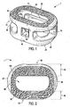
- the implants of the present invention include a body having a top surface, a bottom surface, opposing lateral sides, and opposing anterior and posterior portions.
- the implant includes at least one aperture that extends the entire height of said body. Thus, the aperture extends from the top surface to the bottom surface.
- the implant may further include at least one aperture that extends the entire transverse length of the implant body.
- the substantially hollow portion may be filled with cancellous autograft bone, allograft bone, demineralized bone matrix (DBM), porous synthetic bone graft substitute, bone morphogenic protein (BMP), or combinations thereof
- the implant further includes roughened surface topography on at least a portion of its top and/or bottom surfaces.
- the anterior portion, or trailing edge, of the implant is greater in height than the opposing posterior portion, or leading edge. Thus, the trailing edge is taller than the leading edge.
- the posterior portion and lateral sides may also be generally smooth and highly radiused, thus allowing for easier implantation into the disc space. Thus, the posterior portion has a blunt nosed profile.
- the anterior portion, or trailing edge, of the implant may preferably be configured to engage a delivery device, a surgical driver or other surgical tools.
- the anterior portion may also be substantially flat.
- Certain embodiments of the present invention may be especially suited for placement between adjacent human vertebral bodies.
- the implants of the present invention may be used in procedures such as cervical fusion and Anterior Lumbar Interbody Fusion (ALIF). Certain preferable embodiments do not extend beyond the outer dimensions of the vertebral bodies.
- Interbody spinal implants allow for improved seating over the apophyseal rim of the vertebral body. Still further, interbody spinal implants, as now taught, better utilize this vital surface area over which fusion may occur and may better bear the considerable biomechanical loads presented through the spinal column with minimal interference with other anatomical or neurological spinal structures. Even further, interbody spinal implants, according to certain presently preferred aspects of the present invention, allow for improved visualization of implant seating and fusion assessment. Interbody spinal implants, as now taught, may also may also facilitate osteointegration with the surrounding living bone.
- Anterior interbody spinal implants in accordance with certain aspects of the present invention can be preferably made of a durable material such as stainless steel, stainless steel alloy, titanium, or titanium alloy, but can also be made of other durable materials such as, but not limited to, polymeric, ceramic or composite materials.
- a durable material such as stainless steel, stainless steel alloy, titanium, or titanium alloy
- other durable materials such as, but not limited to, polymeric, ceramic or composite materials.
- certain embodiments of the present invention maybe comprised of a biocompatible, polymeric matrix reinforced with bioactive fillers and/or fibers.
- Certain embodiments of the present invention may be comprised of urethane dimethacrylate (DUDMA)/ tri-ethylene glycol dimethacrylate (TEDGMA) blended resin and a plurality of fillers and fibers including bioactive fillers and E-glass fibers.
- Durable materials may also consist of any number of pure metals and/or metal alloys.
- Titanium and its alloys are generally preferred for certain embodiments of the present invention due to their acceptable, and desirable, strength and biocompatibility.
- certain preferred embodiments of the present interbody spinal implant may have improved structural integrity and may better resist fracture during implantation by impaction. Interbody spinal implants, as now taught, may therefore be used as a distractor during implantation.
- the implants of the present invention include a body having a top surface (10), a bottom surface (20), opposing lateral sides (30), and opposing anterior (40) and posterior (50) portions.
- the implants of the present invention are substantially hollow.
- Preferred embodiments of the present interbody spinal implant have a generally oval-shaped transverse cross-sectional area with smooth and/or rounded lateral sides and rounded posterior-lateral corners.
- Substantially hollow, as used herein, means at least about 33% of the interior volume of the interbody spinal implant is vacant.
- the implant includes at least one aperture (60) that extends the entire height of the implant body. Vertical aperture (60) further defines a transverse rim (100) having greater posterior portion thickness (55) than anterior portion thickness (45).
- the implant may further include at least one aperture (70) that extends the entire transverse length of the implant body. As shown in Figures 5A-5C , these transverse apertures may provide improved visibility of the implant during surgical procedures to ensure proper implant seating and placement, and may also improve post-operative assessment of implant fusion. Still further, the substantially hollow area may be filled with cancellous autograft bone, allograft bone, demineralized bone matrix (DBM), porous synthetic bone graft substitute, bone morphogenic protein (BMP), or combinations thereof, to facilitate the formation of a solid fusion column within the patient's spine.
- BBM demineralized bone matrix
- BMP bone morphogenic protein
- the opposing lateral sides (30) and anterior portion (40) have a rim thickness of 5mm, while the posterior portion (50) has a rim thickness of 7mm.
- posterior rim thickness (55) may allow for better stress sharing between the implant and the adjacent vertebral endplates and helps to compensate for the weaker posterior endplate bone.
- transverse rim (100) having a generally large surface area, contacts the vertebral endplate. This rim may act to better distribute contact stresses upon the implant, and hence minimize the risk of subsidence while maximizing contact with the apophyseal supportive bone.
- the implant further includes roughened surface topography (80) on at least a portion of its top and/or bottom surfaces for gripping adjacent bone and inhibiting migration of the implant.
- Roughened surface topography (80) may be obtained through a variety of techniques including, without limitation, chemical etching, shot peening, plasma etching, laser etching, or abrasive blasting, such as sand or grit blasting.
- the interbody spinal implant may be comprised of titanium, or a titanium alloy, having a roughened surface topography.
- implant fixation may be, at least in part, dependant on the attachment and proliferation of osteoblasts, and like functioning, cells upon the implant surface. Still further, it appears that these cells attach more readily to relatively rough surfaces rather than smooth surfaces. In this manner, a surface may be bioactive due to its ability to facilitate cellular attachment and osteointegration.
- roughened surface topography (80) may better promote the osteointegration of certain preferred embodiments of the present invention. Roughened surface topography (80) may also better grip the vertebral endplate surface(s) and inhibit implant migration upon seating/placement.
- the roughened surface topography is obtained via the repetitive masking and chemical & electrochemical milling processes described in U.S. Patent Nos. 5,258,098 ; 5,507,815 ; 5,922,029 ; and 6,193,762 .
- an etchant mixture of nitric acid and hydrofluoric (HF) acid may be repeatedly applied to a titanium surface to produce an average etch depth of about 0,5334 mm (0.021 inches).
- Interbody spinal implants in accordance with preferred embodiments of the present invention, maybe comprised of titanium, or a titanium alloy, having an average surface roughness of about 100 ⁇ m on its top and/or bottom surfaces. Surface roughness may be measured using a laser profilometer or other standard instrumentation.
- Preferred embodiments of the present invention implant are generally shaped to reduce the risk of subsidence, and improve stability, by maximizing contact with the apophyseal rim of the vertebral endplates. Preferred embodiments may be provided in a variety of anatomical footprints having a medial-lateral width ranging from about 32mm to about 44mm.
- Interbody spinal implants as now taught, generally do not require extensive supplemental or obstructive implantation instrumentation to maintain the prepared disc space during implantation.
- interbody spinal implant and associated implantation method(s) allow for larger sized implants as compared with the size-limited interbody spinal implants known in the art. This allows for greater medal-lateral width and correspondingly greater contact with the apophyseal rim.
- the anterior portion (40), or trailing edge, of the implant is generally greater in height than the opposing posterior portion. Accordingly, the implant may have a lordotic angle to facilitate sagittal alignment. The implant may, thus, better compensate for the generally less supportive bone found in the posterior regions of the vertebral endplate.
- This posterior portion of the interbody implant preferably including the posterior-lateral corners, may also be highly radiused, thus allowing for ease of implantation into the disc space. Thus, the posterior portion has a generally blunt nosed profile.
- the anterior portion (40), or trailing edge, of the implant may also preferably be configured to engage a delivery device, surgical driver, or other surgical tool.
- Certain embodiments of the present invention are particularly suited for use during interbody spinal implant procedures (or vertebral body replacement procedures) and may act as a final distrator during implantation, thus minimizing the instrument load upon the surgeon.
- the spine may first be exposed via an anterior approach and the center of the disc space identified.
- the disc space is then initially prepared for implant insertion by removing vertebral cartilage.
- Soft tissue, and residual cartilage may then also be removed from the vertebral endplates.
- Vertebral distraction may be performed using trials of various-sized embodiments of the interbody spinal implant described herein.
- the determinatively sized interbody implant may then be inserted in the prepared disc space for final placement.
- the distraction procedure and final insertion may also be performed under fluoroscopic guidance.
- the substantially hollow area within the implant body may optionally be, at least partially, filled with bone fusion enabling materials such as, without limitation, cancellous autograft bone, allograft bone, demineralized bone matrix (DBM), porous synthetic bone graft substitute, bone morphogenic protein (BMP), or combinations thereof
- BMP bone morphogenic protein
- Such bone fusion enabling material may be delivered to the interior of the interbody spinal implant using a delivery device mated with an opening (90) in the anterior portion of said implant.
- Interbody spinal implants are generally larger than those currently known in the art, and therefore have a correspondingly larger hollow area which may deliver larger volumes of fusion enabling bone graft material.
- the bone graft material may be delivered such that it fills the full volume, or less than the full volume, of the implant interior and surrounding disc space appropriately.
- the disc space may be accessed using a standard mini open retroperitoneal laparotomy approach.
- the center of the disc space is located by anterior-posterior (AP) fluoroscopy taking care to make sure the pedicles are equidistant from the spinous process.
- the disc space is then incised by making a window in the annulus for insertion of certain embodiments of the present spinal implant.
- the endplates are cleaned of all cartilage with a curette and a size-specific rasp may then be used.
- a lateral c-arm fluoroscopy can be used to follow insertion of the rasp in the posterior disc space.
- the smallest height rasp that touches both endplates e.g., the superior and inferior endplates
- distraction is then accomplished by using implant trials or distractors or both.
- the implant trials, or distractors are solid polished blocks which have a peripheral geometry identical to that of the implant. These distractor blocks may be made in various heights to match the height of the implant.
- An exemplary distrator block may be found in Figure 7 .
- the disc space is adequately distracted by sequentially expanding it with distractors of progressively increasing heights.
- the distractor is then left in the disc space and centering location maybe checked by placing the c-arm back into the AP position. If location is confirmed correct (e.g., centered), the c-arm is turned back into the lateral position.
- the spinal implant is filled with autologous bone graft or bone graft substitute. The distractor is removed and the spinal implant is inserted under c-arm fluoroscopy visualization.
- a size-specific rasp as shown in Figure 8 , preferably minimizes removal of bone, thus minimizing impact to the natural anatomical arch, or concavity, of the vertebral endplate while preserving much of the apophyseal rim.
- Preservation of the anatomical concavity is particularly advantageous in maintaining biomechanical integrity of the spine. For example, in a healthy spine, the transfer of compressive loads from the vertebrae to the spinal disc is achieved via hoop stresses acting upon the natural arch of the endplate. The distribution of forces, and resultant hoop stress, along the natural arch allows the relatively thin shell of subchondral bone to transfer large amounts of load.
- the vertebral endplate natural arch may be significantly removed due to excessive surface preparation for implant placement/seating. This is especially common where the implant is to be seated near the center of the vertebral endplate or the implant is of relatively small medial-lateral width. Breaching the vertebral endplate natural arch disrupts the biomechanical integrity of the vertebral endplate such that shear stress, rather than hoop stress, act upon the endplate surface. This redistribution of stresses may result in subsidence of the implant into the vertebral body. Preferred embodiments of the present surgical method minimize endplate bone removal on the whole, while still allowing for some removal along the vertebral endplate far lateral edges where the subchondral bone is thickest.
- interbody spinal implant includes smooth, rounded, and highly radiused posterior and lateral edges which may minimize extraneous bone removal for endplate preparation.
- Interbody spinal implants of the present invention are durable and can be impacted between the endplates with standard instrumentation.
- certain preferred aspects of the present invention may be used as the final distractor during implantation.
- the disc space may be under-distracted, e.g. distracted to some height less than the height of the interbody spinal implant, to facilitate press-fit implantation.
- certain preferred embodiments of the current invention having a smooth and rounded posterior portion (and lateral sides) may facilitate easier insertion into the disc space.
- those preferred embodiments having roughened surface topography may lessen the risk of excessive bone removal during distraction as compared to implants having teeth, ridges or threads currently known in the art even in view of a press-fit surgical distraction method.
- interbody spinal implant may maintain its position between the vertebral endplates due, at least in part, to resultant annular tension attributable to press-fit surgical implantation and, post-operatively, improved osteointegration at its top and/or bottom surfaces.
- Implant systems currently known in the art require additional instrumentation, such as distraction plugs, to tension the annuls.
- these distraction plugs require further tertiary instrumentation to maintain the lordotic correction during actual spinal implant insertion. If tertiary instrumentation is not used, then some amount of lordotic correction may be lost upon distraction plug removal.
- Interbody spinal implants are particularly advantageous in improving spinal lordosis without the need for tertiary instrumentation, thus reducing the instrument load upon the surgeon. This reduced instrument load may further decrease the complexity, and required steps, of the implantation procedure.
- Certain preferred embodiments may also reduce spondylolythesis via distraction implantation methods, as now taught.
- Traditional implant systems require secondary or additional instrumentation to maintain the relative position of the vertebrae.
- interbody spinal implants as now taught, may be used as the final distractor and thus maintain the relative position of the vertebrae without the need for secondary instrumentation.
Landscapes
- Health & Medical Sciences (AREA)
- Engineering & Computer Science (AREA)
- Biomedical Technology (AREA)
- Neurology (AREA)
- Orthopedic Medicine & Surgery (AREA)
- Cardiology (AREA)
- Oral & Maxillofacial Surgery (AREA)
- Transplantation (AREA)
- Heart & Thoracic Surgery (AREA)
- Vascular Medicine (AREA)
- Life Sciences & Earth Sciences (AREA)
- Animal Behavior & Ethology (AREA)
- General Health & Medical Sciences (AREA)
- Public Health (AREA)
- Veterinary Medicine (AREA)
- Prostheses (AREA)
Claims (10)
- Zwischenkörper-Wirbelsäulenimplantat, das eine allgemein ovale Form im transversalen Querschnitt aufweist, und umfasst:- eine obere Fläche (10), eine untere Fläche (20), gegenüberliegende laterale Seiten (30) und gegenüberliegende vordere (40) und hintere Bereiche (50), wobei der hintere Bereich (50) ein allgemein stumpfes Nasenprofil aufweist,- gekennzeichnet durch:- abgerundete Kanten, die entlang der gesamten Längen zwischen der oberen Fläche (10) und dem hinteren Bereich (50), zwischen der unteren Fläche (20) und dem hinteren Bereich (50), zwischen der oberen Fläche (10) und den lateralen Seiten (30) und zwischen der unteren Fläche (20) und den lateralen Seiten (30) definiert sind, und aufweisend:- spitzwinklige Kanten zwischen den oberen und unteren Flächen (10, 20) und dem vorderen Bereich (40), um einen sicheren Sitz vorzusehen und einem Entfernen standzuhalten, und dadurch gekennzeichnet, dass- das Wirbelsäulenimplantat im Wesentlichen hohl ist und eine zentral angeordnete, vertikale Öffnung (60) aufweist, die sich von der oberen Fläche (10) zur unteren Fläche (20) erstreckt, und einen querlaufenden Rand (100) in den oberen und unteren Flächen (10, 20) mit einer größeren ersten Dicke (55) im Bereich des hinteren Bereichs (50) als eine zweite Dicke (45) im Bereich des vorderen Bereichs (40) definiert, um eine Nutzung der Wirbelsäule zu verbessern, und dadurch, dass zumindest ein Bereich der oberen Fläche (10), der unteren Fläche (20) oder von beiden Flächen eine aufgeraute Oberflächentopographie (80) aufweist.
- Wirbelsäulenimplantat gemäß Anspruch 1, wobei die aufgeraute Oberflächentopographie (80) chemisch geätzt ist.
- Wirbelsäulenimplantat gemäß Anspruch 1, wobei die aufgeraute Oberflächentopographie (80) bioaktiv ist.
- Wirbelsäulenimplantat gemäß Anspruch 1, das ferner zumindest eine Öffnung (70) umfasst, die die gesamte querlaufende Länge des Implantatkörpers verlängert.
- Wirbelsäulenimplantat gemäß Anspruch 1, wobei der vordere Bereich (40) in der vertikalen Höhe allgemein größer als der hintere Bereich (50) ist.
- Wirbelsäulenimplantat gemäß Anspruch 1, wobei der vordere Bereich (40) im Wesentlichen eben ist.
- Wirbelsäulenimplantat gemäß Anspruch 1, wobei der vordere Bereich (40) allgemein angepasst ist, um eine Zuführvorrichtung aufzunehmen.
- Wirbelsäulenimplantat gemäß Anspruch 1, wobei der hintere Bereich (50) zumindest eine Öffnung umfasst.
- Wirbelsäulenimplantat gemäß Anspruch 1, das ferner eine medial-laterale Breite von 32 mm bis ungefähr 44 mm aufweist.
- Wirbelsäulenimplantat gemäß Anspruch 1, das ferner einen spongiösen Knochen aus dem eigenen Körper, einen Knochen von einem Spender, eine demineralisierte Knochenmatrix (DBM), ein poröses synthetisches Knochenersatzmaterial, ein knochenbildendes Protein (BMP) oder Kombinationen davon aufweist.
Applications Claiming Priority (2)
| Application Number | Priority Date | Filing Date | Title |
|---|---|---|---|
| US11/123,359 US7662186B2 (en) | 2005-05-06 | 2005-05-06 | Anterior interbody spinal implant |
| PCT/US2006/017252 WO2006121795A2 (en) | 2005-05-06 | 2006-05-04 | Anterior interbody spinal implant |
Publications (3)
| Publication Number | Publication Date |
|---|---|
| EP1877010A2 EP1877010A2 (de) | 2008-01-16 |
| EP1877010A4 EP1877010A4 (de) | 2011-11-23 |
| EP1877010B1 true EP1877010B1 (de) | 2016-11-02 |
Family
ID=37397103
Family Applications (1)
| Application Number | Title | Priority Date | Filing Date |
|---|---|---|---|
| EP06759086.9A Active EP1877010B1 (de) | 2005-05-06 | 2006-05-04 | Anteriores zwischenkörper-wirbelsäulenimplantat |
Country Status (6)
| Country | Link |
|---|---|
| US (1) | US7662186B2 (de) |
| EP (1) | EP1877010B1 (de) |
| AU (1) | AU2006244482B2 (de) |
| CA (1) | CA2607254C (de) |
| WO (1) | WO2006121795A2 (de) |
| ZA (1) | ZA200710539B (de) |
Families Citing this family (77)
| Publication number | Priority date | Publication date | Assignee | Title |
|---|---|---|---|---|
| US8585766B2 (en) | 2005-05-06 | 2013-11-19 | Titan Spine, Llc | Endplate-preserving spinal implant with an integration plate having durable connectors |
| US9125756B2 (en) | 2005-05-06 | 2015-09-08 | Titan Spine, Llc | Processes for producing regular repeating patterns on surfaces of interbody devices |
| US8617248B2 (en) | 2005-05-06 | 2013-12-31 | Titan Spine, Llc | Spinal implant having variable ratios of the integration surface area to the axial passage area |
| US8551176B2 (en) | 2005-05-06 | 2013-10-08 | Titan Spine, Llc | Spinal implant having a passage for enhancing contact between bone graft material and cortical endplate bone |
| US8403991B2 (en) | 2005-05-06 | 2013-03-26 | Titan Spine Llc | Implant with critical ratio of load bearing surface area to central opening area |
| US8545568B2 (en) | 2005-05-06 | 2013-10-01 | Titan Spine, Llc | Method of using instruments and interbody spinal implants to enhance distraction |
| US8562685B2 (en) | 2005-05-06 | 2013-10-22 | Titan Spine, Llc | Spinal implant and integration plate for optimizing vertebral endplate contact load-bearing edges |
| US11096796B2 (en) | 2005-05-06 | 2021-08-24 | Titan Spine, Llc | Interbody spinal implant having a roughened surface topography on one or more internal surfaces |
| US8591590B2 (en) | 2005-05-06 | 2013-11-26 | Titan Spine, Llc | Spinal implant having a transverse aperture |
| US8480749B2 (en) | 2005-05-06 | 2013-07-09 | Titan Spine, Llc | Friction fit and vertebral endplate-preserving spinal implant |
| US8562684B2 (en) | 2005-05-06 | 2013-10-22 | Titan Spine, Llc | Endplate-preserving spinal implant with an integration plate having a roughened surface topography |
| US9168147B2 (en) | 2005-05-06 | 2015-10-27 | Titan Spine, Llc | Self-deploying locking screw retention device |
| US8585767B2 (en) | 2005-05-06 | 2013-11-19 | Titan Spine, Llc | Endplate-preserving spinal implant with an integration plate having durable connectors |
| US8814939B2 (en) | 2005-05-06 | 2014-08-26 | Titan Spine, Llc | Implants having three distinct surfaces |
| US8585765B2 (en) | 2005-05-06 | 2013-11-19 | Titan Spine, Llc | Endplate-preserving spinal implant having a raised expulsion-resistant edge |
| US8435302B2 (en) | 2005-05-06 | 2013-05-07 | Titan Spine, Llc | Instruments and interbody spinal implants enhancing disc space distraction |
| US20110282454A1 (en) * | 2010-05-14 | 2011-11-17 | Titan Spine, Llc | Interbody Spinal Implant Having Internally Textured Surfaces |
| US8758442B2 (en) | 2005-05-06 | 2014-06-24 | Titan Spine, Llc | Composite implants having integration surfaces composed of a regular repeating pattern |
| US8758443B2 (en) | 2005-05-06 | 2014-06-24 | Titan Spine, Llc | Implants with integration surfaces having regular repeating surface patterns |
| US20120312779A1 (en) | 2005-05-06 | 2012-12-13 | Titian Spine, LLC | Methods for manufacturing implants having integration surfaces |
| US8262737B2 (en) * | 2005-05-06 | 2012-09-11 | Titan Spine, Llc | Composite interbody spinal implant having openings of predetermined size and shape |
| US8992622B2 (en) | 2005-05-06 | 2015-03-31 | Titan Spine, Llc | Interbody spinal implant having a roughened surface topography |
| US8882841B2 (en) * | 2005-09-16 | 2014-11-11 | Us Spine, Inc. | Steerable interbody fusion cage |
| JP2009509591A (ja) * | 2005-09-26 | 2009-03-12 | ウォーソー・オーソペディック・インコーポレーテッド | 前方複合インプラント |
| US20100076559A1 (en) * | 2007-05-04 | 2010-03-25 | Titan Spine, Llc | Composite telescoping anterior interbody spinal implant |
| DE102009014184A1 (de) * | 2008-11-07 | 2010-05-20 | Advanced Medical Technologies Ag | Implantat zur Fusion von Wirbelsäulensegmenten |
| US8821555B2 (en) | 2009-02-11 | 2014-09-02 | Howmedica Osteonics Corp. | Intervertebral implant with integrated fixation |
| RU2552939C2 (ru) | 2009-11-25 | 2015-06-10 | Дифьюжн Текнолоджиз, Инк. | Пост-загрузка покрытых цеолитом пластиков антимикробными ионами металлов |
| BR112012016027B1 (pt) * | 2009-12-11 | 2019-01-15 | Difusion Technologies, Inc. | método de produção de implantes antimicrobianos de polieteretercetona |
| US8945227B2 (en) * | 2010-02-01 | 2015-02-03 | X-Spine Systems, Inc. | Spinal implant co-insertion system and method |
| EP2547292B1 (de) | 2010-03-16 | 2019-04-24 | Pinnacle Spine Group, LLC | Zwischenwirbelimplantate sowie implantateinsatzsysteme |
| CN102946912B (zh) | 2010-05-07 | 2017-09-08 | 扩散技术公司 | 具有增强的亲水性的医学植入物 |
| US9358122B2 (en) | 2011-01-07 | 2016-06-07 | K2M, Inc. | Interbody spacer |
| US10555821B2 (en) * | 2011-09-21 | 2020-02-11 | Tov Inge Vestgaarden | Method and apparatus for spinal interbody fusion including fixation or locking plate |
| US20160106549A1 (en) | 2011-09-21 | 2016-04-21 | Vg Innovations, Llc | Interconnected Locking Plates for Adjacent Spinal Vertebral Bodies |
| US9132021B2 (en) | 2011-10-07 | 2015-09-15 | Pioneer Surgical Technology, Inc. | Intervertebral implant |
| US8992619B2 (en) | 2011-11-01 | 2015-03-31 | Titan Spine, Llc | Microstructured implant surfaces |
| US9380932B1 (en) | 2011-11-02 | 2016-07-05 | Pinnacle Spine Group, Llc | Retractor devices for minimally invasive access to the spine |
| WO2013142480A1 (en) | 2012-03-20 | 2013-09-26 | Titan Spine, Llc | Friction-fit spinal endplate and endplate-preserving method |
| US10376362B2 (en) | 2012-04-05 | 2019-08-13 | Medtronic Vascular Galway | Valve introducers with adjustable deployment mechanism and implantation depth gauge |
| WO2014004121A1 (en) * | 2012-06-27 | 2014-01-03 | Titan Spine, Llc | Spinal implant having a passage of enhancing contact between bone graft material and cortical endplate bone |
| ES2689068T3 (es) * | 2012-07-25 | 2018-11-08 | Titan Spine, Inc. | Implantes que tienen tres superficies diferenciadas |
| US9585764B2 (en) * | 2012-07-26 | 2017-03-07 | Warsaw Orthopedic, Inc. | Bone implant device |
| CN104602629A (zh) | 2012-08-31 | 2015-05-06 | 新南创新公司 | 骨稳固器设备以及使用其的方法 |
| EP2716261A1 (de) | 2012-10-02 | 2014-04-09 | Titan Spine, LLC | Implantate mit selbsteinsetzenden Ankern |
| US9498349B2 (en) | 2012-10-09 | 2016-11-22 | Titan Spine, Llc | Expandable spinal implant with expansion wedge and anchor |
| US10327910B2 (en) | 2013-03-14 | 2019-06-25 | X-Spine Systems, Inc. | Spinal implant and assembly |
| US10070970B2 (en) | 2013-03-14 | 2018-09-11 | Pinnacle Spine Group, Llc | Interbody implants and graft delivery systems |
| CN105592811B (zh) | 2013-08-30 | 2018-06-22 | 新南创新公司 | 脊柱稳定装置 |
| US9615935B2 (en) | 2014-01-30 | 2017-04-11 | Titan Spine, Llc | Thermally activated shape memory spring assemblies for implant expansion |
| AU2016200195B2 (en) | 2015-01-14 | 2020-07-02 | Vb Spine Us Opco Llc | Spinal implant with fluid delivery capabilities |
| AU2016200179B2 (en) | 2015-01-14 | 2020-09-17 | Stryker European Operations Holdings Llc | Spinal implant with porous and solid surfaces |
| US11504236B2 (en) | 2015-03-13 | 2022-11-22 | Medtronic Vascular, Inc. | Delivery device for prosthetic heart valve with capsule adjustment device |
| US10327899B2 (en) | 2015-03-13 | 2019-06-25 | Medtronic Vascular, Inc. | Delivery device for prosthetic heart valve with capsule adjustment device |
| US10758349B2 (en) | 2015-03-13 | 2020-09-01 | Medtronic Vascular, Inc. | Delivery device for prosthetic heart valve with capsule adjustment device |
| CA2930123A1 (en) | 2015-05-18 | 2016-11-18 | Stryker European Holdings I, Llc | Partially resorbable implants and methods |
| WO2017123802A1 (en) | 2016-01-13 | 2017-07-20 | Medtronic Inc. | Delivery device for a stented prosthetic heart valve |
| WO2017156352A1 (en) | 2016-03-11 | 2017-09-14 | Medtronic Vascular Inc. | Delivery device for prosthetic heart valve with capsule adjustment device |
| US10716668B2 (en) | 2017-04-05 | 2020-07-21 | Medtronic, Inc. | Delivery system with anchoring nosecone and method of delivery |
| US11135060B2 (en) | 2017-08-24 | 2021-10-05 | Medtronic Vascular, Inc. | Transseptal delivery systems having a deflecting segment and methods of use |
| US10722351B2 (en) | 2017-08-24 | 2020-07-28 | Medtronic Vascular, Inc. | Transcatheter prosthesis with sealing component, and systems and methods for delivering and deployment thereof |
| US10709556B2 (en) | 2017-08-24 | 2020-07-14 | Medtronic Vascular, Inc. | Transcatheter prosthesis with sealing component, and systems and methods for delivering and deployment thereof |
| AU2018327353B2 (en) | 2017-09-08 | 2024-12-12 | Xtant Medical Holdings, Inc. | Intervertebral implants, instruments, and methods |
| US11071846B2 (en) | 2017-09-14 | 2021-07-27 | Medtronic Vascular, Inc. | Deflection catheter for aiding in bending of a catheter |
| EP3459502B1 (de) | 2017-09-20 | 2024-05-22 | Stryker European Operations Holdings LLC | Wirbelsäulenimplantate |
| USD907771S1 (en) | 2017-10-09 | 2021-01-12 | Pioneer Surgical Technology, Inc. | Intervertebral implant |
| US11766339B1 (en) | 2017-10-24 | 2023-09-26 | Omnia Medical, LLC | Multi-material multi-component spinal implant |
| US10736752B1 (en) | 2017-10-24 | 2020-08-11 | Omnia Medical, LLC | Multi-material multi-component spinal implant |
| US10973658B2 (en) | 2017-11-27 | 2021-04-13 | Titan Spine, Inc. | Rotating implant and associated instrumentation |
| US11135070B2 (en) | 2018-02-14 | 2021-10-05 | Titan Spine, Inc. | Modular adjustable corpectomy cage |
| AU2019213392B2 (en) | 2018-08-09 | 2024-11-28 | Vb Spine Us Opco Llc | Interbody implants and optimization features thereof |
| CN111374806A (zh) * | 2018-12-31 | 2020-07-07 | 王文军 | 自稳型多孔椎间融合器及其制备方法 |
| US20200281727A1 (en) * | 2019-02-12 | 2020-09-10 | PrinterPrezz, Inc. | Selective nano surface modulation of medical devices |
| US11051953B2 (en) | 2019-07-31 | 2021-07-06 | Zavation Medical Products, Llc | Porous spinal implant |
| US11857436B1 (en) | 2019-07-31 | 2024-01-02 | Zavation Medical Products, Llc | Porous spinal implant |
| US11723778B1 (en) | 2021-09-23 | 2023-08-15 | Nofusco Corporation | Vertebral implant system and methods of use |
| US20210402052A1 (en) | 2020-06-30 | 2021-12-30 | Difusion, Inc. | Medical Implants And Methods Of Manufacture |
Family Cites Families (31)
| Publication number | Priority date | Publication date | Assignee | Title |
|---|---|---|---|---|
| US5015247A (en) * | 1988-06-13 | 1991-05-14 | Michelson Gary K | Threaded spinal implant |
| US5609635A (en) * | 1988-06-28 | 1997-03-11 | Michelson; Gary K. | Lordotic interbody spinal fusion implants |
| US5258098A (en) * | 1991-06-17 | 1993-11-02 | Cycam, Inc. | Method of production of a surface adapted to promote adhesion |
| US6491723B1 (en) * | 1996-02-27 | 2002-12-10 | Implant Innovations, Inc. | Implant surface preparation method |
| US5766252A (en) * | 1995-01-24 | 1998-06-16 | Osteonics Corp. | Interbody spinal prosthetic implant and method |
| US5782830A (en) * | 1995-10-16 | 1998-07-21 | Sdgi Holdings, Inc. | Implant insertion device |
| US6423095B1 (en) * | 1995-10-16 | 2002-07-23 | Sdgi Holdings, Inc. | Intervertebral spacers |
| US6033582A (en) * | 1996-01-22 | 2000-03-07 | Etex Corporation | Surface modification of medical implants |
| US6241771B1 (en) * | 1997-08-13 | 2001-06-05 | Cambridge Scientific, Inc. | Resorbable interbody spinal fusion devices |
| US6245108B1 (en) * | 1999-02-25 | 2001-06-12 | Spineco | Spinal fusion implant |
| US6241770B1 (en) * | 1999-03-05 | 2001-06-05 | Gary K. Michelson | Interbody spinal fusion implant having an anatomically conformed trailing end |
| US6342074B1 (en) * | 1999-04-30 | 2002-01-29 | Nathan S. Simpson | Anterior lumbar interbody fusion implant and method for fusing adjacent vertebrae |
| US6485517B1 (en) * | 1999-05-05 | 2002-11-26 | Gary K. Michelson | Nested interbody spinal fusion implants |
| US6830570B1 (en) * | 1999-10-21 | 2004-12-14 | Sdgi Holdings, Inc. | Devices and techniques for a posterior lateral disc space approach |
| US6827740B1 (en) * | 1999-12-08 | 2004-12-07 | Gary K. Michelson | Spinal implant surface configuration |
| TW447286U (en) * | 1999-12-10 | 2001-07-21 | Lin Jr Yi | Intervertebral restorer |
| US6350283B1 (en) * | 2000-04-19 | 2002-02-26 | Gary K. Michelson | Bone hemi-lumbar interbody spinal implant having an asymmetrical leading end and method of installation thereof |
| FR2808673B1 (fr) * | 2000-05-11 | 2002-12-06 | Scient X | Implant intersomatique anterieur lombaire |
| AU2001266623A1 (en) * | 2000-05-30 | 2001-12-11 | Paul S. Lin | Implant for placement between cervical vertebrae |
| US6730127B2 (en) * | 2000-07-10 | 2004-05-04 | Gary K. Michelson | Flanged interbody spinal fusion implants |
| FR2811543B1 (fr) * | 2000-07-12 | 2003-07-04 | Spine Next Sa | Implant intersomatique |
| US6520993B2 (en) * | 2000-12-29 | 2003-02-18 | Depuy Acromed, Inc. | Spinal implant |
| US6890355B2 (en) * | 2001-04-02 | 2005-05-10 | Gary K. Michelson | Artificial contoured spinal fusion implants made of a material other than bone |
| US6558424B2 (en) * | 2001-06-28 | 2003-05-06 | Depuy Acromed | Modular anatomic fusion device |
| US7238203B2 (en) * | 2001-12-12 | 2007-07-03 | Vita Special Purpose Corporation | Bioactive spinal implants and method of manufacture thereof |
| US7077864B2 (en) * | 2002-02-12 | 2006-07-18 | Cross Medical Products, Inc. | Vertebral interbody cage with translatable locking screw |
| DE10248171A1 (de) * | 2002-10-16 | 2004-05-13 | Advanced Medical Technologies Ag | Implantat für die Anordnung zwischen Wirbeln der Wirbelsäule |
| CA2502292C (en) | 2002-10-31 | 2011-07-26 | Spinal Concepts, Inc. | Movable disc implant |
| US7235101B2 (en) * | 2003-09-15 | 2007-06-26 | Warsaw Orthopedic, Inc. | Revisable prosthetic device |
| US7806932B2 (en) * | 2003-08-01 | 2010-10-05 | Zimmer Spine, Inc. | Spinal implant |
| US7875080B2 (en) * | 2004-11-10 | 2011-01-25 | Warsaw Orthopedic, Inc. | Intervertebral spacer |
-
2005
- 2005-05-06 US US11/123,359 patent/US7662186B2/en active Active
-
2006
- 2006-05-04 AU AU2006244482A patent/AU2006244482B2/en not_active Ceased
- 2006-05-04 WO PCT/US2006/017252 patent/WO2006121795A2/en not_active Ceased
- 2006-05-04 CA CA2607254A patent/CA2607254C/en active Active
- 2006-05-04 EP EP06759086.9A patent/EP1877010B1/de active Active
-
2007
- 2007-12-04 ZA ZA200710539A patent/ZA200710539B/xx unknown
Non-Patent Citations (1)
| Title |
|---|
| None * |
Also Published As
| Publication number | Publication date |
|---|---|
| WO2006121795A3 (en) | 2007-11-29 |
| US20060265065A1 (en) | 2006-11-23 |
| AU2006244482A1 (en) | 2006-11-16 |
| EP1877010A4 (de) | 2011-11-23 |
| US7662186B2 (en) | 2010-02-16 |
| ZA200710539B (en) | 2009-07-29 |
| CA2607254C (en) | 2014-01-07 |
| EP1877010A2 (de) | 2008-01-16 |
| WO2006121795B1 (en) | 2008-03-06 |
| WO2006121795A2 (en) | 2006-11-16 |
| AU2006244482B2 (en) | 2011-05-19 |
| CA2607254A1 (en) | 2006-11-16 |
Similar Documents
| Publication | Publication Date | Title |
|---|---|---|
| EP1877010B1 (de) | Anteriores zwischenkörper-wirbelsäulenimplantat | |
| US8992622B2 (en) | Interbody spinal implant having a roughened surface topography | |
| US9433511B2 (en) | Interbody spinal implant having a roughened surface topography | |
| US8551176B2 (en) | Spinal implant having a passage for enhancing contact between bone graft material and cortical endplate bone | |
| US8480749B2 (en) | Friction fit and vertebral endplate-preserving spinal implant | |
| US8403991B2 (en) | Implant with critical ratio of load bearing surface area to central opening area | |
| US8591590B2 (en) | Spinal implant having a transverse aperture | |
| US8617248B2 (en) | Spinal implant having variable ratios of the integration surface area to the axial passage area | |
| US8940053B2 (en) | Spinal implant and integration plate for optimizing vertebral endplate contact load-bearing edges | |
| US8435302B2 (en) | Instruments and interbody spinal implants enhancing disc space distraction | |
| US8545568B2 (en) | Method of using instruments and interbody spinal implants to enhance distraction | |
| US8585765B2 (en) | Endplate-preserving spinal implant having a raised expulsion-resistant edge | |
| US20100076559A1 (en) | Composite telescoping anterior interbody spinal implant | |
| US20140031942A1 (en) | Endplate-preserving spinal implant having a roughened surface topography | |
| AU2013280952B2 (en) | Spinal implant having a passage of enhancing contact between bone graft material and cortical endplate bone |
Legal Events
| Date | Code | Title | Description |
|---|---|---|---|
| PUAI | Public reference made under article 153(3) epc to a published international application that has entered the european phase |
Free format text: ORIGINAL CODE: 0009012 |
|
| 17P | Request for examination filed |
Effective date: 20071127 |
|
| AK | Designated contracting states |
Kind code of ref document: A2 Designated state(s): AT BE BG CH CY CZ DE DK EE ES FI FR GB GR HU IE IS IT LI LT LU LV MC NL PL PT RO SE SI SK TR |
|
| AX | Request for extension of the european patent |
Extension state: AL BA HR MK YU |
|
| R17D | Deferred search report published (corrected) |
Effective date: 20080306 |
|
| DAX | Request for extension of the european patent (deleted) | ||
| A4 | Supplementary search report drawn up and despatched |
Effective date: 20110829 |
|
| RIC1 | Information provided on ipc code assigned before grant |
Ipc: A61F 2/44 20060101AFI20110823BHEP |
|
| DA4 | Supplementary search report drawn up and despatched (deleted) | ||
| RIC1 | Information provided on ipc code assigned before grant |
Ipc: A61F 2/44 20060101AFI20110929BHEP |
|
| RIC1 | Information provided on ipc code assigned before grant |
Ipc: A61F 2/44 20060101AFI20111013BHEP |
|
| RA4 | Supplementary search report drawn up and despatched (corrected) |
Effective date: 20110929 |
|
| RIC1 | Information provided on ipc code assigned before grant |
Ipc: A61F 2/44 20060101AFI20111020BHEP |
|
| GRAP | Despatch of communication of intention to grant a patent |
Free format text: ORIGINAL CODE: EPIDOSNIGR1 |
|
| INTG | Intention to grant announced |
Effective date: 20160527 |
|
| GRAS | Grant fee paid |
Free format text: ORIGINAL CODE: EPIDOSNIGR3 |
|
| GRAA | (expected) grant |
Free format text: ORIGINAL CODE: 0009210 |
|
| AK | Designated contracting states |
Kind code of ref document: B1 Designated state(s): AT BE BG CH CY CZ DE DK EE ES FI FR GB GR HU IE IS IT LI LT LU LV MC NL PL PT RO SE SI SK TR |
|
| REG | Reference to a national code |
Ref country code: GB Ref legal event code: FG4D |
|
| REG | Reference to a national code |
Ref country code: AT Ref legal event code: REF Ref document number: 841036 Country of ref document: AT Kind code of ref document: T Effective date: 20161115 Ref country code: CH Ref legal event code: EP |
|
| REG | Reference to a national code |
Ref country code: IE Ref legal event code: FG4D |
|
| REG | Reference to a national code |
Ref country code: DE Ref legal event code: R096 Ref document number: 602006050768 Country of ref document: DE |
|
| PG25 | Lapsed in a contracting state [announced via postgrant information from national office to epo] |
Ref country code: LV Free format text: LAPSE BECAUSE OF FAILURE TO SUBMIT A TRANSLATION OF THE DESCRIPTION OR TO PAY THE FEE WITHIN THE PRESCRIBED TIME-LIMIT Effective date: 20161102 |
|
| REG | Reference to a national code |
Ref country code: NL Ref legal event code: MP Effective date: 20161102 |
|
| REG | Reference to a national code |
Ref country code: LT Ref legal event code: MG4D |
|
| REG | Reference to a national code |
Ref country code: AT Ref legal event code: MK05 Ref document number: 841036 Country of ref document: AT Kind code of ref document: T Effective date: 20161102 |
|
| PG25 | Lapsed in a contracting state [announced via postgrant information from national office to epo] |
Ref country code: GR Free format text: LAPSE BECAUSE OF FAILURE TO SUBMIT A TRANSLATION OF THE DESCRIPTION OR TO PAY THE FEE WITHIN THE PRESCRIBED TIME-LIMIT Effective date: 20170203 Ref country code: LT Free format text: LAPSE BECAUSE OF FAILURE TO SUBMIT A TRANSLATION OF THE DESCRIPTION OR TO PAY THE FEE WITHIN THE PRESCRIBED TIME-LIMIT Effective date: 20161102 Ref country code: NL Free format text: LAPSE BECAUSE OF FAILURE TO SUBMIT A TRANSLATION OF THE DESCRIPTION OR TO PAY THE FEE WITHIN THE PRESCRIBED TIME-LIMIT Effective date: 20161102 Ref country code: SE Free format text: LAPSE BECAUSE OF FAILURE TO SUBMIT A TRANSLATION OF THE DESCRIPTION OR TO PAY THE FEE WITHIN THE PRESCRIBED TIME-LIMIT Effective date: 20161102 |
|
| REG | Reference to a national code |
Ref country code: FR Ref legal event code: PLFP Year of fee payment: 12 |
|
| PG25 | Lapsed in a contracting state [announced via postgrant information from national office to epo] |
Ref country code: PT Free format text: LAPSE BECAUSE OF FAILURE TO SUBMIT A TRANSLATION OF THE DESCRIPTION OR TO PAY THE FEE WITHIN THE PRESCRIBED TIME-LIMIT Effective date: 20170302 Ref country code: FI Free format text: LAPSE BECAUSE OF FAILURE TO SUBMIT A TRANSLATION OF THE DESCRIPTION OR TO PAY THE FEE WITHIN THE PRESCRIBED TIME-LIMIT Effective date: 20161102 Ref country code: AT Free format text: LAPSE BECAUSE OF FAILURE TO SUBMIT A TRANSLATION OF THE DESCRIPTION OR TO PAY THE FEE WITHIN THE PRESCRIBED TIME-LIMIT Effective date: 20161102 Ref country code: IS Free format text: LAPSE BECAUSE OF FAILURE TO SUBMIT A TRANSLATION OF THE DESCRIPTION OR TO PAY THE FEE WITHIN THE PRESCRIBED TIME-LIMIT Effective date: 20170302 Ref country code: PL Free format text: LAPSE BECAUSE OF FAILURE TO SUBMIT A TRANSLATION OF THE DESCRIPTION OR TO PAY THE FEE WITHIN THE PRESCRIBED TIME-LIMIT Effective date: 20161102 Ref country code: ES Free format text: LAPSE BECAUSE OF FAILURE TO SUBMIT A TRANSLATION OF THE DESCRIPTION OR TO PAY THE FEE WITHIN THE PRESCRIBED TIME-LIMIT Effective date: 20161102 |
|
| PG25 | Lapsed in a contracting state [announced via postgrant information from national office to epo] |
Ref country code: EE Free format text: LAPSE BECAUSE OF FAILURE TO SUBMIT A TRANSLATION OF THE DESCRIPTION OR TO PAY THE FEE WITHIN THE PRESCRIBED TIME-LIMIT Effective date: 20161102 Ref country code: SK Free format text: LAPSE BECAUSE OF FAILURE TO SUBMIT A TRANSLATION OF THE DESCRIPTION OR TO PAY THE FEE WITHIN THE PRESCRIBED TIME-LIMIT Effective date: 20161102 Ref country code: DK Free format text: LAPSE BECAUSE OF FAILURE TO SUBMIT A TRANSLATION OF THE DESCRIPTION OR TO PAY THE FEE WITHIN THE PRESCRIBED TIME-LIMIT Effective date: 20161102 Ref country code: RO Free format text: LAPSE BECAUSE OF FAILURE TO SUBMIT A TRANSLATION OF THE DESCRIPTION OR TO PAY THE FEE WITHIN THE PRESCRIBED TIME-LIMIT Effective date: 20161102 Ref country code: CZ Free format text: LAPSE BECAUSE OF FAILURE TO SUBMIT A TRANSLATION OF THE DESCRIPTION OR TO PAY THE FEE WITHIN THE PRESCRIBED TIME-LIMIT Effective date: 20161102 |
|
| REG | Reference to a national code |
Ref country code: DE Ref legal event code: R097 Ref document number: 602006050768 Country of ref document: DE |
|
| PG25 | Lapsed in a contracting state [announced via postgrant information from national office to epo] |
Ref country code: LU Free format text: LAPSE BECAUSE OF NON-PAYMENT OF DUE FEES Effective date: 20170531 Ref country code: BG Free format text: LAPSE BECAUSE OF FAILURE TO SUBMIT A TRANSLATION OF THE DESCRIPTION OR TO PAY THE FEE WITHIN THE PRESCRIBED TIME-LIMIT Effective date: 20170202 Ref country code: BE Free format text: LAPSE BECAUSE OF FAILURE TO SUBMIT A TRANSLATION OF THE DESCRIPTION OR TO PAY THE FEE WITHIN THE PRESCRIBED TIME-LIMIT Effective date: 20161102 Ref country code: IT Free format text: LAPSE BECAUSE OF FAILURE TO SUBMIT A TRANSLATION OF THE DESCRIPTION OR TO PAY THE FEE WITHIN THE PRESCRIBED TIME-LIMIT Effective date: 20161102 |
|
| PLBE | No opposition filed within time limit |
Free format text: ORIGINAL CODE: 0009261 |
|
| STAA | Information on the status of an ep patent application or granted ep patent |
Free format text: STATUS: NO OPPOSITION FILED WITHIN TIME LIMIT |
|
| 26N | No opposition filed |
Effective date: 20170803 |
|
| PG25 | Lapsed in a contracting state [announced via postgrant information from national office to epo] |
Ref country code: SI Free format text: LAPSE BECAUSE OF FAILURE TO SUBMIT A TRANSLATION OF THE DESCRIPTION OR TO PAY THE FEE WITHIN THE PRESCRIBED TIME-LIMIT Effective date: 20161102 |
|
| REG | Reference to a national code |
Ref country code: CH Ref legal event code: PL |
|
| PG25 | Lapsed in a contracting state [announced via postgrant information from national office to epo] |
Ref country code: MC Free format text: LAPSE BECAUSE OF FAILURE TO SUBMIT A TRANSLATION OF THE DESCRIPTION OR TO PAY THE FEE WITHIN THE PRESCRIBED TIME-LIMIT Effective date: 20161102 |
|
| REG | Reference to a national code |
Ref country code: IE Ref legal event code: MM4A |
|
| PG25 | Lapsed in a contracting state [announced via postgrant information from national office to epo] |
Ref country code: LI Free format text: LAPSE BECAUSE OF NON-PAYMENT OF DUE FEES Effective date: 20170531 Ref country code: CH Free format text: LAPSE BECAUSE OF NON-PAYMENT OF DUE FEES Effective date: 20170531 |
|
| PG25 | Lapsed in a contracting state [announced via postgrant information from national office to epo] |
Ref country code: LU Free format text: LAPSE BECAUSE OF NON-PAYMENT OF DUE FEES Effective date: 20170504 |
|
| PG25 | Lapsed in a contracting state [announced via postgrant information from national office to epo] |
Ref country code: IE Free format text: LAPSE BECAUSE OF NON-PAYMENT OF DUE FEES Effective date: 20170504 |
|
| REG | Reference to a national code |
Ref country code: FR Ref legal event code: PLFP Year of fee payment: 13 |
|
| REG | Reference to a national code |
Ref country code: DE Ref legal event code: R081 Ref document number: 602006050768 Country of ref document: DE Owner name: TITAN SPINE, INC., MEQUON, US Free format text: FORMER OWNER: TITAN SPINE, LLC, MEQUON, WIS., US |
|
| REG | Reference to a national code |
Ref country code: FR Ref legal event code: CA Effective date: 20180919 Ref country code: FR Ref legal event code: CJ Effective date: 20180919 |
|
| PG25 | Lapsed in a contracting state [announced via postgrant information from national office to epo] |
Ref country code: HU Free format text: LAPSE BECAUSE OF FAILURE TO SUBMIT A TRANSLATION OF THE DESCRIPTION OR TO PAY THE FEE WITHIN THE PRESCRIBED TIME-LIMIT; INVALID AB INITIO Effective date: 20060504 |
|
| PG25 | Lapsed in a contracting state [announced via postgrant information from national office to epo] |
Ref country code: CY Free format text: LAPSE BECAUSE OF NON-PAYMENT OF DUE FEES Effective date: 20161102 |
|
| PG25 | Lapsed in a contracting state [announced via postgrant information from national office to epo] |
Ref country code: TR Free format text: LAPSE BECAUSE OF FAILURE TO SUBMIT A TRANSLATION OF THE DESCRIPTION OR TO PAY THE FEE WITHIN THE PRESCRIBED TIME-LIMIT Effective date: 20161102 |
|
| PGFP | Annual fee paid to national office [announced via postgrant information from national office to epo] |
Ref country code: GB Payment date: 20200423 Year of fee payment: 15 |
|
| GBPC | Gb: european patent ceased through non-payment of renewal fee |
Effective date: 20210504 |
|
| PG25 | Lapsed in a contracting state [announced via postgrant information from national office to epo] |
Ref country code: GB Free format text: LAPSE BECAUSE OF NON-PAYMENT OF DUE FEES Effective date: 20210504 |
|
| PGFP | Annual fee paid to national office [announced via postgrant information from national office to epo] |
Ref country code: DE Payment date: 20250423 Year of fee payment: 20 |
|
| PGFP | Annual fee paid to national office [announced via postgrant information from national office to epo] |
Ref country code: FR Payment date: 20250423 Year of fee payment: 20 |