EP1876556B1 - Programmatic control of RFID tags - Google Patents
Programmatic control of RFID tags Download PDFInfo
- Publication number
- EP1876556B1 EP1876556B1 EP07252397A EP07252397A EP1876556B1 EP 1876556 B1 EP1876556 B1 EP 1876556B1 EP 07252397 A EP07252397 A EP 07252397A EP 07252397 A EP07252397 A EP 07252397A EP 1876556 B1 EP1876556 B1 EP 1876556B1
- Authority
- EP
- European Patent Office
- Prior art keywords
- mode
- rfid tag
- signal
- operating
- reader
- Prior art date
- Legal status (The legal status is an assumption and is not a legal conclusion. Google has not performed a legal analysis and makes no representation as to the accuracy of the status listed.)
- Ceased
Links
Images


Classifications
-
- G—PHYSICS
- G06—COMPUTING OR CALCULATING; COUNTING
- G06K—GRAPHICAL DATA READING; PRESENTATION OF DATA; RECORD CARRIERS; HANDLING RECORD CARRIERS
- G06K19/00—Record carriers for use with machines and with at least a part designed to carry digital markings
- G06K19/06—Record carriers for use with machines and with at least a part designed to carry digital markings characterised by the kind of the digital marking, e.g. shape, nature, code
- G06K19/067—Record carriers with conductive marks, printed circuits or semiconductor circuit elements, e.g. credit or identity cards also with resonating or responding marks without active components
- G06K19/07—Record carriers with conductive marks, printed circuits or semiconductor circuit elements, e.g. credit or identity cards also with resonating or responding marks without active components with integrated circuit chips
- G06K19/077—Constructional details, e.g. mounting of circuits in the carrier
- G06K19/07749—Constructional details, e.g. mounting of circuits in the carrier the record carrier being capable of non-contact communication, e.g. constructional details of the antenna of a non-contact smart card
- G06K19/07773—Antenna details
-
- G—PHYSICS
- G06—COMPUTING OR CALCULATING; COUNTING
- G06K—GRAPHICAL DATA READING; PRESENTATION OF DATA; RECORD CARRIERS; HANDLING RECORD CARRIERS
- G06K19/00—Record carriers for use with machines and with at least a part designed to carry digital markings
- G06K19/06—Record carriers for use with machines and with at least a part designed to carry digital markings characterised by the kind of the digital marking, e.g. shape, nature, code
- G06K19/067—Record carriers with conductive marks, printed circuits or semiconductor circuit elements, e.g. credit or identity cards also with resonating or responding marks without active components
- G06K19/07—Record carriers with conductive marks, printed circuits or semiconductor circuit elements, e.g. credit or identity cards also with resonating or responding marks without active components with integrated circuit chips
- G06K19/073—Special arrangements for circuits, e.g. for protecting identification code in memory
- G06K19/07309—Means for preventing undesired reading or writing from or onto record carriers
- G06K19/07372—Means for preventing undesired reading or writing from or onto record carriers by detecting tampering with the circuit
- G06K19/07381—Means for preventing undesired reading or writing from or onto record carriers by detecting tampering with the circuit with deactivation or otherwise incapacitation of at least a part of the circuit upon detected tampering
-
- G—PHYSICS
- G06—COMPUTING OR CALCULATING; COUNTING
- G06K—GRAPHICAL DATA READING; PRESENTATION OF DATA; RECORD CARRIERS; HANDLING RECORD CARRIERS
- G06K19/00—Record carriers for use with machines and with at least a part designed to carry digital markings
- G06K19/06—Record carriers for use with machines and with at least a part designed to carry digital markings characterised by the kind of the digital marking, e.g. shape, nature, code
- G06K19/067—Record carriers with conductive marks, printed circuits or semiconductor circuit elements, e.g. credit or identity cards also with resonating or responding marks without active components
- G06K19/07—Record carriers with conductive marks, printed circuits or semiconductor circuit elements, e.g. credit or identity cards also with resonating or responding marks without active components with integrated circuit chips
- G06K19/073—Special arrangements for circuits, e.g. for protecting identification code in memory
- G06K19/07309—Means for preventing undesired reading or writing from or onto record carriers
- G06K19/07345—Means for preventing undesired reading or writing from or onto record carriers by activating or deactivating at least a part of the circuit on the record carrier, e.g. ON/OFF switches
-
- G—PHYSICS
- G06—COMPUTING OR CALCULATING; COUNTING
- G06K—GRAPHICAL DATA READING; PRESENTATION OF DATA; RECORD CARRIERS; HANDLING RECORD CARRIERS
- G06K19/00—Record carriers for use with machines and with at least a part designed to carry digital markings
- G06K19/06—Record carriers for use with machines and with at least a part designed to carry digital markings characterised by the kind of the digital marking, e.g. shape, nature, code
- G06K19/067—Record carriers with conductive marks, printed circuits or semiconductor circuit elements, e.g. credit or identity cards also with resonating or responding marks without active components
- G06K19/07—Record carriers with conductive marks, printed circuits or semiconductor circuit elements, e.g. credit or identity cards also with resonating or responding marks without active components with integrated circuit chips
- G06K19/073—Special arrangements for circuits, e.g. for protecting identification code in memory
- G06K19/07309—Means for preventing undesired reading or writing from or onto record carriers
- G06K19/07372—Means for preventing undesired reading or writing from or onto record carriers by detecting tampering with the circuit
- G06K19/07381—Means for preventing undesired reading or writing from or onto record carriers by detecting tampering with the circuit with deactivation or otherwise incapacitation of at least a part of the circuit upon detected tampering
- G06K19/0739—Means for preventing undesired reading or writing from or onto record carriers by detecting tampering with the circuit with deactivation or otherwise incapacitation of at least a part of the circuit upon detected tampering the incapacitated circuit being part of an antenna
-
- G—PHYSICS
- G06—COMPUTING OR CALCULATING; COUNTING
- G06K—GRAPHICAL DATA READING; PRESENTATION OF DATA; RECORD CARRIERS; HANDLING RECORD CARRIERS
- G06K19/00—Record carriers for use with machines and with at least a part designed to carry digital markings
- G06K19/06—Record carriers for use with machines and with at least a part designed to carry digital markings characterised by the kind of the digital marking, e.g. shape, nature, code
- G06K19/067—Record carriers with conductive marks, printed circuits or semiconductor circuit elements, e.g. credit or identity cards also with resonating or responding marks without active components
- G06K19/07—Record carriers with conductive marks, printed circuits or semiconductor circuit elements, e.g. credit or identity cards also with resonating or responding marks without active components with integrated circuit chips
- G06K19/077—Constructional details, e.g. mounting of circuits in the carrier
- G06K19/07749—Constructional details, e.g. mounting of circuits in the carrier the record carrier being capable of non-contact communication, e.g. constructional details of the antenna of a non-contact smart card
-
- G—PHYSICS
- G06—COMPUTING OR CALCULATING; COUNTING
- G06K—GRAPHICAL DATA READING; PRESENTATION OF DATA; RECORD CARRIERS; HANDLING RECORD CARRIERS
- G06K7/00—Methods or arrangements for sensing record carriers, e.g. for reading patterns
- G06K7/10—Methods or arrangements for sensing record carriers, e.g. for reading patterns by electromagnetic radiation, e.g. optical sensing; by corpuscular radiation
- G06K7/10009—Methods or arrangements for sensing record carriers, e.g. for reading patterns by electromagnetic radiation, e.g. optical sensing; by corpuscular radiation sensing by radiation using wavelengths larger than 0.1 mm, e.g. radio-waves or microwaves
- G06K7/10158—Methods or arrangements for sensing record carriers, e.g. for reading patterns by electromagnetic radiation, e.g. optical sensing; by corpuscular radiation sensing by radiation using wavelengths larger than 0.1 mm, e.g. radio-waves or microwaves methods and means used by the interrogation device for reliably powering the wireless record carriers using an electromagnetic interrogation field
Definitions
- the present invention relates to radio frequency identification (RFID) technology, and more particularly to techniques that enable a device to advertise its mode of operation using an RFID tag attached to the device.
- RFID radio frequency identification
- RFID tags are commonly used for inventory control and tracking of objects. It is well known that RFID chips are only readable from a few centimeters away, unless they are coupled to an antenna. However, once properly attached to an antenna, they are then visible from a much greater distance, for example, up to 10 meters in the case of RFID chips in the 2.4 GHz transmission band.
- An RFID tag generally comprises a microchip coupled to an antenna.
- RFID tags are configured to respond to interrogation signals received from an RFID reader. The response signal transmitted from the RFID tag may then be read and used by the reader.
- An antenna attached to an RFID tag may be used for receiving an interrogation signal from an RFID reader and for transmitting signals in response to the interrogation signal.
- An active RFID comprises a battery or other power supply that is used as a partial or complete source of power for the tag's microchip circuitry and antenna. Due to the presence of the battery, active tags can generally be read over longer distances than other tags. Active tags however tend to be physically larger and more expensive than passive tags.
- a passive tag does not comprise an onboard power supply such as a battery.
- the power for a passive tag is supplied by the reader.
- a passive tag is activated by radio frequency (RF) energy in the interrogation signal transmitted from an RFID reader.
- RF radio frequency
- a passive RFID tag generally comprises a coiled antenna that forms a magnetic field upon encountering radio waves from a reader. The passive RFID tag draws power from the magnetic coupling. The electrical current induced in the antenna by the incoming radio frequency signal provides enough power for a transponder in the tag to power up and transmit a response. Most passive tags transmit response signals by backscattering the carrier signal from the reader.
- the antenna in a passive tag may be designed to both collect power from the incoming signal and also to transmit the outbound backscatter signal. Since passive RFID tags do not require batteries, they are much smaller and less expensive than active tags and have a very long life span.
- Embodiments of the present invention provide techniques that enable a device to advertise its mode of operation using an RFID tag attached to the device.
- techniques are provided for programmatically controlling an RFID tag.
- An RFID tag attached to a device is programmatically enabled or disabled depending upon the mode(s) of operation of the device-
- the RFID tag is able to transmit a signal when enabled and not able to transmit a signal when disabled.
- a device can efficiently indicate or advertise its mode of operation to an RFID reader or sensor.
- a first aspect of the invention provides a method of controlling an RFID tag associated with a device as set out in Claim 1. Preferred features of this aspect are set out in Claims 2 to 8.
- a second aspect of the invention provides a deice as set out in Claim 9.
- Preferred features of this aspect of the invention are set out in Claims 10 to 16.
- the invention also provides a method of determining a mode of operation of a device as set out in Claims 17 to 19 and a system as set out in Claims 20 to 22.
- Embodiments of the present invention provide techniques that enable a device to advertise its mode of operation using an RFID tag attached to the device.
- An RFID tag attached to a device is programmatically enabled or disabled depending upon a mode(s) of operation of the device.
- a device can efficiently indicate or advertise its mode of operation to an RFID reader or sensor.
- Fig. 1 depicts a simplified block diagram of a system 100 incorporating an embodiment of the present invention.
- system 100 comprises a reader (or sensor) 102 and a device 104 comprising an RFID tag 106.
- Reader 102 may be any apparatus that is capable of receiving signals (e.g., radio frequency signals) transmitted from an RFID tag.
- reader 102 may be configured to transmit interrogation RF signals to one or more RFID tags.
- reader 102 may send an RF interrogation signal 112 to RFID tag 106 using a transmitter and receive a response signal 114 transmitted by RFID tag 106 in response to the interrogation signal using a receiver.
- Reader 102 may comprise an antenna that facilitates the transmission and reception of RF signals.
- reader 102 may be configured to process the response signal received from RFID tag 106 and initiate performance of one or more actions based upon the processing. The processing may include determining a device mode of operation based upon the response signal and taking appropriate actions. A reader 102 may also be configured to communicate the response signal received from RFID tag 106 to other devices or applications for further processing. Reader 102 may comprise a processor module for performing the processing.
- RFID tag 106 is configured to receive RF interrogation signals 112 from one or more readers and to transmit RF response signals in response to the interrogation signals.
- RFID tags are generally packaged such that they can be easily attached to objects. There are different ways in which RFID tag 106 may be attached to device 104. For example, the RFID tag may be glued to the device, clipped to the device, embedded in the device, included as a component of the device, and the like.
- RFID tag 106 comprises an antenna 108 coupled to a tag chip 110.
- Antenna 108 facilitates reception and transmission of RF signals to and from RFID tag 106.
- Tag chip 110 may comprise various components that facilitate the functionality of RFID tag 106. These components may include, for example, an RFID transponder, a modulator, a demodulator, a memory (e.g., an EEPROM), control logic, RFID circuitry, etc.
- RFID tag 106 may be an active RFID tag, a passive tag, a battery-assisted passive tag, or other type of RFID tag.
- tag 106 may also comprise a power source such as a battery (not shown).
- antenna 108 may be a coiled antenna that is configured to form a magnetic coupling with radio frequency waves received from a reader. The electric current generated from the magnetic coupling may be used to power the passive RFID tag.
- RFID tag 106 may be programmatically controlled based upon a mode of operation of device 104. In one embodiment, RFID tag 106 is controlled such that the tag is either enabled or disabled based upon a mode of operation of device 104. When enabled, RFID tag 106 is able to transmit signals from the tag. When disabled, RFID tag 106 is not able to transmit signals from the tag and as a result that tag would appear as if it is not present to an RFID reader. For example, RFID tag 106 may be enabled when device 104 operates in a first mode and may be disabled when device 104 operates in a second mode.
- a controller apparatus 116 is used to programmatically enable or disable RFID tag 106.
- Controller 116 may be embodied in various different forms and may include one or more modules or components. Controller 116 may be separate from RFID tag 106 or may be part of RFID tag 106.
- Controller 116 is configured to receive a signal representative of or based upon a mode of operation of device 104 and disable or enable RFID tag 106 based upon the signal. For example, controller 116 may receive a first signal when device 104 is operating in a first mode and a second signal when device 104 is operating in a second mode that is different from the first mode. Controller 116 may enable RFID tag 106 upon receiving the first signal and may disable RFID tag 106 upon receiving the second signal. The receipt of the signal and the enabling or disabling of RFID tag 106 is performed automatically without requiring any user action or intervention resulting in RFID tag 106 being programmatically controlled.
- controller 116 may receive the signal that causes RFID tag 106 to be disabled or enabled from a processing module 118.
- controller 116 may receive a signal from a processing module 118 via link 120.
- Link 120 may be a wired or wireless link.
- Link 120 may include any mechanism that enables processing module 118 to send a signal, either directly or indirectly, to controller 116 or to RFID tag 106.
- Link 120 may include multiple links and/or devices.
- controller 116 comprises an I/O pin that receives, either directly or indirectly, a signal from processing module 118. The signal received by the I/O pin is representative of the mode of operation of device 104 and causes controller apparatus 116 to disable or enable RFID tag 106.
- processing module 118 By controlling the signal that is sent to controller 116, processing module 118 programmatically controls the operation of RFID tag 106.
- Processing module 118 may be implemented in software (e.g., code or instructions that may be stored on a computer-readable storage medium) executed by a processor, hardware, or combinations thereof.
- processing module 118 is configured to determine a mode of operation of the device and send a signal representative of the determined mode to controller 116 such that the signal causes controller 116 to enable or disable RFID tag 106.
- processing module 118 may determine the mode of operation of device 104, determine whether RFID tag 106 is to be enabled or disabled based upon the determined mode of operation, and then send an appropriate signal to controller 116 that causes RFID tag 106 to be enabled or disabled.
- processing module 118 may be performed programmatically without any user intervention.
- controller 116 is configured to enable or disable RFID tag 106. In this manner, RFID tag 106 is programmatically controlled without requiring any user intervention or action.
- the modes of operation for a device may depend on the characteristics and capabilities of the device and may be different for different devices. These modes may be user-configurable in certain embodiments. Whether an RFID tag is to be enabled or disabled for a particular mode of operation for a particular device may also be user-configurable.
- RFID tag 106 may be enabled when device 104 is operating in a specific mode (or modes) and disabled when device 104 is not operating in the specific mode or modes.
- the RFID tag on a device may be enabled when the device is powered on and may be automatically disabled when the device is powered off. In this manner, the RFID tag is programmatically, without requiring an user interaction, enabled or disabled based upon the power-on/power-off mode of the device.
- the RFID tag on the camera may be enabled to transmit signals when the camera is in an information capture mode (e.g., is in "image capture” mode or "video capture” mode) and may be disabled from transmitting signals when the camera is powered off or not operating in an information capture mode. In this manner, the camera can advertise to a reader that the camera is in information capture mode.
- an information capture mode e.g., is in "image capture” mode or "video capture” mode
- an RFID tag when enabled it is capable of transmitting RF signals that may be read by a reader 102. Accordingly, when enabled, the RFID tag is visible to a reader. For example, in the case of a passive RFID tag, the RFID tag may receive an interrogation signal from an RF reader and, if enabled, be able to transmit a response signal by backscattering the interrogation signal from the reader. In the case of an active RFID tag, when enabled, the RFID tag may use the onboard power supply (e.g., a battery) to transmit a signal to the reader. The signal transmitted by an active tag may be transmitted in response to an interrogation signal received by the active tag.
- the onboard power supply e.g., a battery
- the signal transmitted from an enabled RFID tag 106 may be read by reader 102.
- Reader 102 may ascertain the operating mode (or modes) of device 104 based upon the received signal.
- reader 102 may be preconfigured with information identifying one or more device operation modes for which the RFID tag of the device is enabled. Accordingly, when reader 102 receives a signal from an RFID tag associated with a device, it indicates to reader 102 that the RFID tag is enabled, which in turn indicates that the device is operating in a mode (or modes) for which the RFID tag is enabled. If there is only one device operation mode for which the RFID tag is enabled, then reception of the signal from the RFID tag by reader 102 indicates to reader 102 that the device is operating in that one device operation mode.
- the RFID tag attached to a device may be enabled for more than one mode of operation of the device.
- reception of a response signal from the device RFID tag indicates to reader 102 that the device is operating in at least one of the multiple operation modes for which the RFID tag is enabled.
- the signal transmitted from the RFID tag may comprise information that may be used to determine a specific mode of operation of device 104.
- a response signal transmitted from RFID tag 106 attached to device 104 and received by reader 102 may also comprise information that may be used by reader 102 to find characteristics of the device.
- the response signal may comprise information (e.g., an identifier stored in the memory of the RFID tag) identifying the device from which the signal is received, etc.
- Reader 102 may initiate one or more actions based upon the response signal received from tag 106.
- reader 102 may determine a mode of operation of device 104 based upon the response signal received from RFID tag 106 of the device and initiate one or more actions corresponding to the determined mode.
- an RFID tag When an RFID tag is disabled, as described above, it is not capable of transmitting RF signals. For example, if a reader 102 sends an interrogation signal to a disabled RFID tag, the disabled tag will be unable to transmit a signal responsive to the interrogation signal. In this case, reader 102 will not receive any response signal from the RFID tag. The RFID tag is thus not visible to reader 102.
- not receiving a response signal in response to an interrogation signal may also indicate to reader 102 that device 104 is operating in a certain mode(s). For example, when reader 102 knows that a device 104 with an RFID tag is present within reading distance, non-response to an interrogation signal may indicate to reader 102 that device 104 is operating in a mode (or modes) where the RFID tag attached to device is disabled. Reader 102 may be preconfigured with information identifying one or more modes of operation for a device for which the RFID tag of the device is disabled.
- the device is capable of conveying or advertising information related to its mode of operation.
- This information may be used by the reader to initiate one or more actions.
- reader 102 may initiate one or more actions upon determining that device 104 is operating in a particular mode or modes.
- One or more actions may also be initiated if device 104 is determined to be not operating in a particular mode or modes.
- initiation of an action may be performed by reader 102.
- reader 102 may convey the information transmitted from device 104 to another device or application which may process the transmitted information and then initiate a responsive action.
- Fig. 2A depicts a simplified flowchart 200 showing processing performed to enable or disable an RFID tag attached to a device according to an embodiment of the present invention.
- the processing depicted in flowchart 200 may be performed by hardware modules, software modules (e.g., code or instructions that may be stored on a computer-readable storage medium and executed by a processor), or combinations thereof.
- controller 116 receives a signal representative of or based upon a mode of operation of a device (step 202). For example, if a device is operating in a first mode for which the RFID tag attached to the device is to be enabled, then the signal received is such that it represents or is based upon the first mode and which causes the RFID tag attached to the device to be enabled.
- Controller 116 enables or disables an RFID tag attached to the device based upon the signal received in 202 (step 204).
- the processing depicted in flowchart 200 is performed automatically without any user input or interaction.
- the RFID tag attached to the device is programmatically controlled based upon a mode of operation of the device. The device is thus able to convey or advertise its mode of operation to a reader.
- controller apparatus 116 may simply receive a signal and disable or enable the RFID tag attached to the device based upon the signal. No specific step is needed to determine the mode of operation of the device or to determine whether the RFID tag is to be disabled or enabled. The mode of operation is inherent or implicit in the signal received by controller apparatus 116 and the RFID tag is automatically enabled or disabled responsive to the signal.
- controller 116 may receive a signal when the device has power and receive no signal when the device is powered off. This may be done by connecting an input pin of controller 116 to the device power. Accordingly, when the device has power, a signal is received on the input pin of controller 116 that causes the RFID tag to be enabled. When the device is in powered-off mode, no signal is received on the input pin of controller 116 and as a result the RFID tag is disabled. Thus, the signal received by the controller automatically controls whether the RFID tag is enabled or disabled.
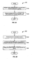
- Fig. 2B depicts another simplified flowchart 220 showing processing performed to enable or disable an RFID tag attached to a device according to an embodiment of the present invention.
- the processing depicted in flowchart 200 may be performed by hardware modules, software modules (e.g., code or instructions that may be stored on a computer-readable storage medium and executed by a processor), or combinations thereof.
- a mode of operation of a device is determined (step 222).
- the device mode of operation may be determined by a processing module 118 of device 104.
- a determination is then made, based upon the mode of operation determined in 222, whether an RFID tag associated with the device is to be enabled or disabled (step 224). In one embodiment, the determination may be made by processing module 118.
- the RFID tag is then disabled or enabled (step 226).
- processing module 118 may generate and send a signal to controller 116 that causes controller 116 to enable or disable the RFID tag attached to the device.
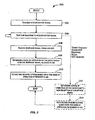
- Fig. 3 depicts a simplified flowchart 300 showing processing performed by a reader according to an embodiment of the present invention.
- the processing depicted in flowchart 300 may be performed by hardware modules of a reader, software modules (e.g., code or instructions that may be stored on a computer-readable storage medium and executed by a processor of the reader), or combinations thereof.
- the processor of the reader may execute one or more software modules to perform the processing.
- a reader may transmit an interrogation signal using a transmitter (step 302).
- the interrogation signal may be directed towards a specific RFID tag or may be generally transmitted in multiple directions.
- the reader then waits to receive a response to the interrogation signal (step 304).
- the reader may comprise a receiver to receive response signals.
- the reader may be configured to wait a preconfigured amount of time for a response signal. If the reader receives a response signal (step 306), then the reader may determine a mode of operation of a device that was the source of the response signal (step 308). Receipt of the response signal indicates to the reader that the device from which the response signal was received is operating in a mode for which the RFID tag attached to the device is enabled.
- the response signal may comprise information identifying a specific mode of operation of the device.
- the reader may initiate one or more actions based upon the mode of operation determined in 308 (step 310).
- the response signal may comprise information that may be used to identify the device from which the signal was received.
- non-reception of a response signal may also be relevant to the reader.
- the reader may know a device with an associated RFID tag is present within reading distance of the reader.
- the reader may be configured to wait a preconfigured period of time for a response signal. Given that the reader knows about the presence of the device, if the reader does not receive a response signal in the preconfigured time, it indicates to the reader that the device is operating in a mode for which the RFID tag attached to the device is disabled. Accordingly, the reader may determine the mode of operation of the device due to non-reception of a response signal (step 312). The reader may then cause one or more actions to be initiated based upon the mode determined in 312 (step 314).
- an RFID tag may be disabled by interrupting the power of the RFID tag, such that without power the RFID tag is disabled and not able to transmit.
- tags available today however have the tag logic and the power harvesting circuitry on-board on the tag chip itself. As a result, for these types of tags, the tag chip has to be programmed to interrupt the power or allow for some other external interruption of power.
- an RFID tag may be disabled by disabling the antenna used by the RFID tag to transmit signals.
- the antenna of an RFID tag is disabled by clamping together the poles of the antenna under programmatic control. When clamped, this disables the antenna, and as a result the RFID tag cannot harvest power or identify the interrogation signal received from a reader or transmit signals.
- Fig. 4 depicts a simplified block diagram of an RFID tag 400 that may be programmatically controlled according to an embodiment of the present invention. It should be apparent that RFID tag 400 depicted in Fig. 4 merely illustrates an example of a standard tag that may be used according to an embodiment of the present invention and does not limit the scope of the invention as recited in the claims.
- RFID tag 400 depicted in Fig. 4 is a passive tag that is configured to harvest RF energy (e.g., interrogation signal) coming in from a reader. Once powered by the incoming energy, RFID tag 400 uses the harvested energy to transmit a response signal to the reader. RFID tag 400 may send the response signal via backscatter. In this manner, RFID tag 400 attached to a device is able to transmit a response signal without requiring any external power source on the RFID tag to power the RFID tag and without using power from the device.
- RF energy e.g., interrogation signal
- RFID tag 400 comprises a tag chip 401 attached to an antenna 402 that is configured to receive and transmit RF signals.
- Tag chip 401 may comprise one or more stages 404 coupled to a circuit block 406.
- Each stage 404 may comprise one or more electronic components that enable tag 400 to harvest energy.
- Stage 404 may be repeated for more power.
- Circuit block 406 may comprise various components that facilitate the functionality of RFID tag 400. These components may include for example a modulator, a demodulator, a memory (e.g., an EEPROM), control logic, RFID circuitry, etc.
- an RFID tag may be programmatically controlled by disabling the antenna of the RFID tag.
- Various techniques may be used to disable an antenna.
- an antenna is disabled by clamping the antenna.
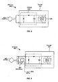
- Fig. 5 is a simplified block diagram of a system for programmatically controlling an RFID tag (such as the RFID tag depicted in Fig. 4 ) according to an embodiment of the present invention.
- the system depicted in Fig. 5 is merely illustrative of an embodiment incorporating the present invention and does not limit the scope of the invention as recited in the claims.
- One of ordinary skill in the art would recognize other variations, modifications, and alternatives.
- RFID tag 400 comprises antenna 402 coupled to tag chip 401.
- the controller apparatus that is used to automatically enable or disable tag 400 comprises a reed relay 502 coupled to an I/O pin 504.
- An example of a reed relay is Digikey PN 420-10160ND.
- Reed relay 502 programmatically clamps the poles of antenna 402 based upon a signal received on I/O pin 504, thereby enabling or disabling antenna 402. The signal received on I/O pin 504 thus determines whether the RFID tag is enabled or disabled.
- the RFID tag is enabled only when a high signal is received on pin 504.
- the poles of antenna 402 are not clamped, thereby enabling the antenna so that RFID tag 400 is able to transmit using antenna 402.
- the poles of antenna 402 are clamped, thereby disabling the antenna from transmitting a signal in response to an interrogation signal, which effectively disables RFID tag 400 from being able to transmit a signal.
- the device to which the RFID tag is attached operates in a mode for which the RFID tag is to be enabled, then a high signal is input to pin 504 thereby enabling antenna 402 which effectively enables RFID tag 400 to transmit and advertise its mode of operation. If the device operates in a mode for which the RFID tag is to be disabled, then a low signal is input to pin 504 thereby disabling antenna 402 which effectively disables RFID tag 400.
- Table A summarizes the different states of the RFID tag in response to device power, signal on pin 504, and the reed relay state.
- the antenna poles are clamped and as a result the antenna is unable to transmit or receive data, thereby disabling RFID tag 400.
- the antenna poles are not clamped and as a result the antenna is able to transmit or receive data, thereby enabling RFID tag 400.
- the reed relay is open and the RFID tag is enabled and able to transmit and respond to an interrogation signal from a reader only when the I/O pin is driven to 5V (high).
- the reed relay is closed and the RFID tag is disabled (SILENT) when the I/O pin is 0V (low).
- the signal on I/O pin 504 may be driven by a processor module that is configured to determine the mode of operation of the device and based upon the mode generate a signal that appropriately disables or enables the RFID tag.
- the RFID transponder is programmatically controlled without requiring any user intervention.
- Table A The last row of Table A is not possible (and hence not applicable) since, for the embodiment depicted in Fig. 5 , when the device power is off the I/O pin state cannot be driven to 5V.
- Fig. 6 is another simplified block diagram of a system for programmatically controlling an RFID tag according to an embodiment of the present invention.
- the system depicted in Fig. 6 is merely illustrative of an embodiment incorporating the present invention and does not limit the scope of the invention as recited in the claims.
- One of ordinary skill in the art would recognize other variations, modifications, and alternatives.
- the controller apparatus that is used to programmatically disable or enable RFID tag 400 comprises a field effect transistor (FET) 602 connected to pin 604.
- FET 602 is configured to short or open antenna 402 based upon the signal received on pin 604.
- FET 602 when the signal on I/O pin 604 is low, FET 602 does not conduct, antenna 402 is open, and RFID tag 400 is able to transmit in response to an interrogation signal received from a reader.
- signal on I/O pin 604 is high, FET 602 conducts, the poles of antenna 402 are shorted, and RFID tag 400 is unable to transmit and is silent. Accordingly, RFID tag 400 is enabled or disabled based upon the signal provided to I/O pin 604.
- the configuration shown in Fig. 6 may be used to advertise when a device is in power-on mode.
- RFID tag is enabled when the device has power (power-on mode) and is disabled when the device does not have power (power-off mode).
- I/O pin 604 may receive a low signal when the device has power which causes antenna 402 to be open and the RFID tag is able to transmit and advertise the device's power-on mode.
- I/O pin 604 may receive a high signal when the device is powered-off resulting in antenna 402 being shorted and unable to transmit, thereby disabling RFID tag 400.
- Fig. 7 is a simplified block diagram of a system for programmatically controlling an RFID tag by hindering tag power according to an embodiment of the present invention.
- the system depicted in Fig. 7 is merely illustrative of an embodiment incorporating the present invention and does not limit the scope of the invention as recited in the claims.
- One of ordinary skill in the art would recognize other variations, modifications, and alternatives.
- the controller apparatus that is used to enable or disable RFID tag 400 comprises a MOSFET 702 (e.g., an n-channel MOSFET (2n7002)) connected to circuit block 406 and the gate of the MOSFET is connected to device power.
- MOSFET 702 e.g., an n-channel MOSFET (2n7002)
- the gate control to the MOSFET is low, and there is no power to circuit block 406 because the source/drain are open, and as a result no response (backscatter) can be made to the reader, and the RFID transponder is silent or disabled.
- the gate control When the device power is on, the gate control is on, current flows between the source and the drain on the MOSFET. and as a result the circuit block 406 is powered (through a slight voltage drop in the FET), and the RFID transponder is able to respond (is enabled).
- the programmatic control of an RFID tag on a device enables the device to advertise or convey information regarding a mode of operation of the device. This may be achieved without requiring any power source for the RFID tag. Advertising of the mode requires extremely little power which may be harnessed from the reader rather than from the device to which the RFID tag is attached.
- Embodiments of the present invention cause a device to be visible to a reader when the RFID tag attached to the device is enabled. This may be done without costing the device itself any power.
- the transmission capability of an RFID tag may be programmatically controlled.
- An RFID tag may be disabled by programmatically shutting down the transmission capability of the RFID tag.
- the RFID tag is not "always on” and as a result the use of the programmable RFID tag is less intrusive.
- the device to which the RFID tag is attached does not have to be powered on in order to determine a mode of operation of the device.
- Programmable RFID tags as described above may be used in embedded devices. Because embedded devices are always limited by available power, the fact that the reader is expending the power rather than the RFID tag or device itself is of significant value.
- Embodiments of the invention allow a device to broadcast (communicate) its operating mode without costing the device any power usage at all since the power is harvested from energy received from the reader.
- Embodiments of the present invention may be used for a variety of different applications.
- the applications described below are examples of different ways in which embodiments of the present invention may be used. These examples are not intended to limit the scope of the present invention as recited in the claims.
- a rewritable RFID tag without programmatic control always transmits an identifier in response to a reader query. This means that it is always detectable at a distance.
- a person concerned with privacy might worry that their location will be tracked through such a device, whether they wish to advertise their presence or not.
- a programmatically controlled RFID tag does not respond at all unless the operating mode dictates a response. Users can worry less about unintended tracking, because they are in control of the device's operating mode.
Landscapes
- Engineering & Computer Science (AREA)
- Computer Hardware Design (AREA)
- Physics & Mathematics (AREA)
- General Physics & Mathematics (AREA)
- Theoretical Computer Science (AREA)
- Microelectronics & Electronic Packaging (AREA)
- Computer Security & Cryptography (AREA)
- General Engineering & Computer Science (AREA)
- Computer Networks & Wireless Communication (AREA)
- Electromagnetism (AREA)
- Health & Medical Sciences (AREA)
- Toxicology (AREA)
- General Health & Medical Sciences (AREA)
- Artificial Intelligence (AREA)
- Computer Vision & Pattern Recognition (AREA)
- Near-Field Transmission Systems (AREA)
Applications Claiming Priority (1)
| Application Number | Priority Date | Filing Date | Title |
|---|---|---|---|
| US11/482,343 US9342777B2 (en) | 2006-07-06 | 2006-07-06 | Programmatic control of RFID tags |
Publications (2)
| Publication Number | Publication Date |
|---|---|
| EP1876556A1 EP1876556A1 (en) | 2008-01-09 |
| EP1876556B1 true EP1876556B1 (en) | 2011-08-03 |
Family
ID=38510422
Family Applications (1)
| Application Number | Title | Priority Date | Filing Date |
|---|---|---|---|
| EP07252397A Ceased EP1876556B1 (en) | 2006-07-06 | 2007-06-13 | Programmatic control of RFID tags |
Country Status (3)
| Country | Link |
|---|---|
| US (3) | US9342777B2 (enExample) |
| EP (1) | EP1876556B1 (enExample) |
| JP (1) | JP5114109B2 (enExample) |
Families Citing this family (39)
| Publication number | Priority date | Publication date | Assignee | Title |
|---|---|---|---|---|
| US9342777B2 (en) * | 2006-07-06 | 2016-05-17 | Ricoh Company, Ltd. | Programmatic control of RFID tags |
| US7626504B2 (en) * | 2007-04-13 | 2009-12-01 | At&T Intellectual Property I, L.P. | System and apparatus for silencing communication devices |
| US8638191B2 (en) * | 2007-09-28 | 2014-01-28 | Stryker Corporation | Wireless hand-control of device by means of wireless button |
| US9241114B1 (en) * | 2007-10-02 | 2016-01-19 | At&T Intellectual Property I, L.P. | Uniform universal remote configuration |
| EP2662808B1 (en) * | 2008-06-09 | 2016-07-20 | Nokia Technologies Oy | Apparatuses and methods relating to radio frequency identification (RFID) tags |
| US20100141445A1 (en) * | 2008-12-08 | 2010-06-10 | Savi Networks Inc. | Multi-Mode Commissioning/Decommissioning of Tags for Managing Assets |
| JP5308927B2 (ja) * | 2009-06-23 | 2013-10-09 | 株式会社日立製作所 | 個品情報管理装置及び方法 |
| US8456302B2 (en) * | 2009-07-14 | 2013-06-04 | Savi Technology, Inc. | Wireless tracking and monitoring electronic seal |
| CN103548071B (zh) * | 2009-07-14 | 2016-10-26 | 迪尔·美吉克有限公司 | 安全封条 |
| US8432274B2 (en) | 2009-07-31 | 2013-04-30 | Deal Magic, Inc. | Contextual based determination of accuracy of position fixes |
| CN102713949A (zh) * | 2009-08-17 | 2012-10-03 | 交易魔法公司 | 资产的情境感知监视 |
| US8314704B2 (en) * | 2009-08-28 | 2012-11-20 | Deal Magic, Inc. | Asset tracking using alternative sources of position fix data |
| US8334773B2 (en) | 2009-08-28 | 2012-12-18 | Deal Magic, Inc. | Asset monitoring and tracking system |
| US20110050397A1 (en) * | 2009-08-28 | 2011-03-03 | Cova Nicholas D | System for generating supply chain management statistics from asset tracking data |
| US20110054979A1 (en) * | 2009-08-31 | 2011-03-03 | Savi Networks Llc | Physical Event Management During Asset Tracking |
| US20110068909A1 (en) * | 2009-09-24 | 2011-03-24 | Jung Che Chang | Battery-free remote controller |
| WO2011103160A1 (en) * | 2010-02-16 | 2011-08-25 | Dynamics Inc. | Systems and methods for drive circuits for dynamic magnetic stripe communications devices |
| KR101139490B1 (ko) | 2010-09-08 | 2012-05-02 | 에스케이하이닉스 주식회사 | Rfid 장치 |
| JP5896653B2 (ja) * | 2011-09-06 | 2016-03-30 | キヤノン株式会社 | 画像形成装置、画像形成装置の制御方法、及びプログラム |
| CA2892796C (en) * | 2012-12-03 | 2020-05-26 | Evolution Engineering Inc. | Downhole probe centralizer |
| CN113850097A (zh) * | 2012-12-14 | 2021-12-28 | 艾利丹尼森公司 | 配置为用于直接交互的rfid装置 |
| US20140184388A1 (en) * | 2013-01-03 | 2014-07-03 | William Thomas Van Loan | End of the line detection apparatus |
| FR3004607B1 (fr) * | 2013-04-11 | 2016-12-23 | Airbus Operations Sas | Procede et systeme d'ecriture, de mise a jour et de lecture des donnees statiques et dynamiques d'identification d'un equipement aeronautique |
| JP6302296B2 (ja) * | 2014-03-11 | 2018-03-28 | キヤノン株式会社 | 通信装置、制御方法、及びプログラム |
| US9760747B2 (en) * | 2014-03-11 | 2017-09-12 | Canon Kabushiki Kaisha | Communication apparatus and method for controlling the same |
| US10133585B2 (en) * | 2014-06-02 | 2018-11-20 | Sony Corporation | Information processing apparatus including tags for controlling operation modes |
| JP6438245B2 (ja) * | 2014-09-05 | 2018-12-12 | キヤノン株式会社 | 通信装置およびその制御方法、プログラム |
| CN104850841B (zh) * | 2015-05-20 | 2017-11-07 | 银江股份有限公司 | 一种结合rfid与视频识别的老人异常行为监测方法 |
| US10679108B2 (en) * | 2016-08-15 | 2020-06-09 | Intelligent Imaging Systems, Inc. | Transponder |
| EP3343450B1 (fr) * | 2016-12-29 | 2020-02-05 | The Swatch Group Research and Development Ltd | Objet portable comportant un dispositif de connexion en champ proche |
| EP3343451B1 (fr) * | 2016-12-29 | 2022-09-21 | The Swatch Group Research and Development Ltd | Objet portable comportant un dispositif de connexion en champ proche |
| EP3586506A4 (en) * | 2017-02-27 | 2021-04-14 | Isolynx, LLC | SYSTEMS AND METHODS FOR TRACKING AND CONTROLLING A MOBILE CAMERA FOR IMAGE OBJECTS OF INTEREST |
| US11162750B1 (en) * | 2019-09-16 | 2021-11-02 | Donald L. Weeks | Detection of firearms in a security zone using radio frequency identification tag embedded within weapon bolt carrier |
| US10878207B1 (en) * | 2019-09-24 | 2020-12-29 | Stmicroelectronics, Inc. | Power supply package with built-in radio frequency identification tag |
| DE102021124751A1 (de) * | 2021-09-24 | 2023-03-30 | Tridonic Gmbh & Co Kg | Konfigurierung von Komponenten eines Beleuchtungssystems mittels sperrbarem Transponder |
| FR3131814B1 (fr) * | 2022-01-07 | 2024-10-11 | St Microelectronics Rousset | Système avec lecteur, transpondeur et capteurs et procédé de fonctionnement |
| US12229339B2 (en) * | 2022-07-18 | 2025-02-18 | Georgia Tech Research Corporation | Method and tactical passive RFID transponder gloves with morphological actuation |
| CN115278936B (zh) * | 2022-07-28 | 2024-04-26 | 龙兴(杭州)航空电子有限公司 | 用于机载航电设备的无线终端射频发射的阻断方法及系统 |
| US12462124B1 (en) * | 2024-03-06 | 2025-11-04 | United States Of America As Represented By The Administrator Of Nasa | Range extension and priority handling for wearable, ubiquitous RFID tag |
Citations (1)
| Publication number | Priority date | Publication date | Assignee | Title |
|---|---|---|---|---|
| EP1622064A2 (en) * | 2004-07-26 | 2006-02-01 | Yamaha Corporation | RFID tag-containing apparatus |
Family Cites Families (38)
| Publication number | Priority date | Publication date | Assignee | Title |
|---|---|---|---|---|
| US5790946A (en) | 1993-07-15 | 1998-08-04 | Rotzoll; Robert R. | Wake up device for a communications system |
| US5446447A (en) * | 1994-02-16 | 1995-08-29 | Motorola, Inc. | RF tagging system including RF tags with variable frequency resonant circuits |
| US6362737B1 (en) * | 1998-06-02 | 2002-03-26 | Rf Code, Inc. | Object Identification system with adaptive transceivers and methods of operation |
| US5884425A (en) | 1997-05-23 | 1999-03-23 | Avery Dennison Corporation | Anti-tamper tag with theft protection |
| JP2000516791A (ja) | 1997-06-27 | 2000-12-12 | コーニンクレッカ フィリップス エレクトロニクス エヌ ヴィ | 無線通信装置における電源の切換え |
| US6025780A (en) | 1997-07-25 | 2000-02-15 | Checkpoint Systems, Inc. | RFID tags which are virtually activated and/or deactivated and apparatus and methods of using same in an electronic security system |
| US5982284A (en) | 1997-09-19 | 1999-11-09 | Avery Dennison Corporation | Tag or label with laminated thin, flat, flexible device |
| US6768415B1 (en) | 1997-10-03 | 2004-07-27 | Micron Technology, Inc. | Wireless identification device, RFID device with push-on/push-off switch, method of manufacturing wireless identification device |
| US7012504B2 (en) | 2002-04-01 | 2006-03-14 | Micron Technology, Inc. | Wireless identification device, RFID device with push-on/push off switch, and method of manufacturing wireless identification device |
| US6677852B1 (en) * | 1999-09-22 | 2004-01-13 | Intermec Ip Corp. | System and method for automatically controlling or configuring a device, such as an RFID reader |
| US6955299B1 (en) * | 1999-12-17 | 2005-10-18 | Centre For Wireless Communications Of National University Of Singapore | System and method for using a smart card |
| EP1662064A1 (en) | 2000-04-24 | 2006-05-31 | Hunter Douglas Inc. | Compressible structural panel |
| US6758000B2 (en) | 2001-01-10 | 2004-07-06 | Avery Dennison Corporation | Livestock security tag assembly |
| US6951596B2 (en) | 2002-01-18 | 2005-10-04 | Avery Dennison Corporation | RFID label technique |
| JP2003036427A (ja) * | 2001-03-02 | 2003-02-07 | Sony Corp | 半導体集積回路装置、携帯端末装置、および決済方法 |
| US6851617B2 (en) | 2002-04-19 | 2005-02-08 | Avery Dennison Corporation | Laser imageable RFID label/tag |
| US6847912B2 (en) * | 2002-05-07 | 2005-01-25 | Marconi Intellectual Property (Us) Inc. | RFID temperature device and method |
| EP1516269B1 (en) * | 2002-06-26 | 2009-09-30 | Nokia Corporation | System, apparatus, and method for effecting network connections via wireless devices using radio frequency identification |
| US6867983B2 (en) | 2002-08-07 | 2005-03-15 | Avery Dennison Corporation | Radio frequency identification device and method |
| US6940408B2 (en) | 2002-12-31 | 2005-09-06 | Avery Dennison Corporation | RFID device and method of forming |
| US6863220B2 (en) * | 2002-12-31 | 2005-03-08 | Massachusetts Institute Of Technology | Manually operated switch for enabling and disabling an RFID card |
| US6914562B2 (en) | 2003-04-10 | 2005-07-05 | Avery Dennison Corporation | RFID tag using a surface insensitive antenna structure |
| JP4568276B2 (ja) | 2003-07-07 | 2010-10-27 | エーブリー デニソン コーポレイション | 変化可能な特性を有するrfid装置 |
| US7176784B2 (en) * | 2004-01-21 | 2007-02-13 | Battelle Memorial Institute K1-53 | Multi-mode radio frequency device |
| US7309014B2 (en) | 2004-03-04 | 2007-12-18 | Ethicon, Inc. | Sterilizer cassette handling system with dual visual code reading |
| WO2006049374A1 (en) | 2004-04-07 | 2006-05-11 | Kun-Hong Lee | Rfid sensor and ubiquitous sensor network system thereof |
| US7433649B2 (en) * | 2004-09-10 | 2008-10-07 | Motorola, Inc. | Tag for facilitating interaction with a wireless communication device |
| US9020430B2 (en) * | 2004-10-12 | 2015-04-28 | Nokia Corporation | Methods, apparatus, systems and computer program products for energy management of short-range communication modules in mobile terminal devices |
| JP2006229855A (ja) * | 2005-02-21 | 2006-08-31 | Konica Minolta Photo Imaging Inc | 撮像装置 |
| US7474211B2 (en) * | 2005-02-22 | 2009-01-06 | Bradley Allen Kramer | System and method for killing a RFID tag |
| CA2497629A1 (en) * | 2005-02-28 | 2006-08-28 | Eduard Levin | Radio frequency identification of tagged articles |
| US20060261950A1 (en) * | 2005-03-29 | 2006-11-23 | Symbol Technologies, Inc. | Smart radio frequency identification (RFID) items |
| US7327260B2 (en) * | 2005-05-19 | 2008-02-05 | International Business Machines Corporation | System and method to record environmental condition on an RFID tag |
| JP4508948B2 (ja) * | 2005-06-01 | 2010-07-21 | シャープ株式会社 | 携帯端末装置 |
| US7408463B2 (en) * | 2005-09-30 | 2008-08-05 | Intel Corporation | Radio frequency identification tag |
| FR2891639B1 (fr) * | 2005-10-04 | 2007-11-30 | Atmel Corp | Moyen pour desactiver un dispositif sans contact. |
| US9342777B2 (en) | 2006-07-06 | 2016-05-17 | Ricoh Company, Ltd. | Programmatic control of RFID tags |
| US8395521B2 (en) | 2009-02-06 | 2013-03-12 | University Of Dayton | Smart aerospace structures |
-
2006
- 2006-07-06 US US11/482,343 patent/US9342777B2/en active Active
-
2007
- 2007-06-13 EP EP07252397A patent/EP1876556B1/en not_active Ceased
- 2007-06-27 JP JP2007169598A patent/JP5114109B2/ja not_active Expired - Fee Related
-
2013
- 2013-03-22 US US13/849,424 patent/US9396426B2/en active Active
-
2016
- 2016-07-19 US US15/214,373 patent/US20170076193A1/en not_active Abandoned
Patent Citations (1)
| Publication number | Priority date | Publication date | Assignee | Title |
|---|---|---|---|---|
| EP1622064A2 (en) * | 2004-07-26 | 2006-02-01 | Yamaha Corporation | RFID tag-containing apparatus |
Also Published As
| Publication number | Publication date |
|---|---|
| US20130234835A1 (en) | 2013-09-12 |
| US9396426B2 (en) | 2016-07-19 |
| US20170076193A1 (en) | 2017-03-16 |
| US20080006696A1 (en) | 2008-01-10 |
| JP2008016022A (ja) | 2008-01-24 |
| EP1876556A1 (en) | 2008-01-09 |
| JP5114109B2 (ja) | 2013-01-09 |
| US9342777B2 (en) | 2016-05-17 |
Similar Documents
| Publication | Publication Date | Title |
|---|---|---|
| EP1876556B1 (en) | Programmatic control of RFID tags | |
| US20190384948A1 (en) | NFC Tags with Proximity Detection | |
| KR101126921B1 (ko) | Rfid 네트워크에서 작동하는 장치, 비-응답 모드로 진입하고 비-응답 모드로부터 나가는 방법 및 컴퓨터 판독가능 저장 매체 | |
| US9189725B2 (en) | Activation and indication of an RF field on a device including a chip | |
| US20190074868A1 (en) | Smart Tags with Multiple Interactions | |
| US8121532B2 (en) | Radio frequency identification tag and operating method thereof | |
| WO2008088398A2 (en) | System, method, and device for controlled user tracking | |
| EP2740112B1 (en) | Reduction of false alarms in asset tracking | |
| CN104488006A (zh) | 连接智能手机的usb存储器 | |
| Lee et al. | A multilevel home security system (mhss) | |
| US7791469B2 (en) | Short range wireless tracking and event notification system for portable devices | |
| WO2016180645A1 (en) | Rfid transponder, rfid transponder arrangement and method for communication between an rfid transponder and a reading device | |
| US7567780B2 (en) | Data exchange systems and methods employing RF data transmission | |
| KR20060099990A (ko) | 이동 통신 단말기의 벨 모드 전환 장치 및 방법 | |
| KR20190079012A (ko) | 스마트 미러를 이용한 농장 관리 시스템 | |
| KR20120119582A (ko) | 알에프아이디를 이용한 물품 분실 방지 시스템 및 그 방법 | |
| KR100782078B1 (ko) | Mms를 이용한 휴대 단말기의 위치 정보 제공 방법 | |
| JP2006185234A (ja) | Rfid及び通信動作距離設定方法 | |
| JP2006352574A (ja) | 無線通信装置,無線信号処理方法,およびコンピュータプログラム | |
| KR101328595B1 (ko) | 통신 단말기 및 그의 무선식별 방지 방법 | |
| US8295678B2 (en) | Universal method of controlling the recording of audio-visual presentations by data processor controlled recording devices | |
| KR100600967B1 (ko) | 비접촉식 전자칩을 갖는 이동통신단말기 및 그를 이용한긴급상황 알림방법 | |
| EP3050001B1 (en) | A method and system for initiating a function in an electronic device | |
| KR20080013132A (ko) | Rfid를 이용한 이동통신단말기와 그 사용방지 방법 | |
| KR20060095151A (ko) | 알에프 태그를 이용한 단말기 제어 방법 |
Legal Events
| Date | Code | Title | Description |
|---|---|---|---|
| PUAI | Public reference made under article 153(3) epc to a published international application that has entered the european phase |
Free format text: ORIGINAL CODE: 0009012 |
|
| 17P | Request for examination filed |
Effective date: 20070619 |
|
| AK | Designated contracting states |
Kind code of ref document: A1 Designated state(s): AT BE BG CH CY CZ DE DK EE ES FI FR GB GR HU IE IS IT LI LT LU LV MC MT NL PL PT RO SE SI SK TR |
|
| AX | Request for extension of the european patent |
Extension state: AL BA HR MK YU |
|
| AKX | Designation fees paid |
Designated state(s): DE FR GB |
|
| 17Q | First examination report despatched |
Effective date: 20081117 |
|
| GRAC | Information related to communication of intention to grant a patent modified |
Free format text: ORIGINAL CODE: EPIDOSCIGR1 |
|
| GRAP | Despatch of communication of intention to grant a patent |
Free format text: ORIGINAL CODE: EPIDOSNIGR1 |
|
| GRAS | Grant fee paid |
Free format text: ORIGINAL CODE: EPIDOSNIGR3 |
|
| GRAA | (expected) grant |
Free format text: ORIGINAL CODE: 0009210 |
|
| AK | Designated contracting states |
Kind code of ref document: B1 Designated state(s): DE FR GB |
|
| REG | Reference to a national code |
Ref country code: GB Ref legal event code: FG4D |
|
| REG | Reference to a national code |
Ref country code: DE Ref legal event code: R096 Ref document number: 602007016243 Country of ref document: DE Effective date: 20110929 |
|
| PLBE | No opposition filed within time limit |
Free format text: ORIGINAL CODE: 0009261 |
|
| STAA | Information on the status of an ep patent application or granted ep patent |
Free format text: STATUS: NO OPPOSITION FILED WITHIN TIME LIMIT |
|
| 26N | No opposition filed |
Effective date: 20120504 |
|
| REG | Reference to a national code |
Ref country code: DE Ref legal event code: R097 Ref document number: 602007016243 Country of ref document: DE Effective date: 20120504 |
|
| REG | Reference to a national code |
Ref country code: FR Ref legal event code: PLFP Year of fee payment: 10 |
|
| REG | Reference to a national code |
Ref country code: FR Ref legal event code: PLFP Year of fee payment: 11 |
|
| REG | Reference to a national code |
Ref country code: FR Ref legal event code: PLFP Year of fee payment: 12 |
|
| PGFP | Annual fee paid to national office [announced via postgrant information from national office to epo] |
Ref country code: GB Payment date: 20220622 Year of fee payment: 16 |
|
| PGFP | Annual fee paid to national office [announced via postgrant information from national office to epo] |
Ref country code: FR Payment date: 20220628 Year of fee payment: 16 |
|
| PGFP | Annual fee paid to national office [announced via postgrant information from national office to epo] |
Ref country code: DE Payment date: 20220620 Year of fee payment: 16 |
|
| REG | Reference to a national code |
Ref country code: DE Ref legal event code: R119 Ref document number: 602007016243 Country of ref document: DE |
|
| GBPC | Gb: european patent ceased through non-payment of renewal fee |
Effective date: 20230613 |
|
| PG25 | Lapsed in a contracting state [announced via postgrant information from national office to epo] |
Ref country code: DE Free format text: LAPSE BECAUSE OF NON-PAYMENT OF DUE FEES Effective date: 20240103 Ref country code: GB Free format text: LAPSE BECAUSE OF NON-PAYMENT OF DUE FEES Effective date: 20230613 |
|
| PG25 | Lapsed in a contracting state [announced via postgrant information from national office to epo] |
Ref country code: FR Free format text: LAPSE BECAUSE OF NON-PAYMENT OF DUE FEES Effective date: 20230630 |