EP1874529B1 - Shaping device for producing goods from a material strand - Google Patents
Shaping device for producing goods from a material strand Download PDFInfo
- Publication number
- EP1874529B1 EP1874529B1 EP06708792.4A EP06708792A EP1874529B1 EP 1874529 B1 EP1874529 B1 EP 1874529B1 EP 06708792 A EP06708792 A EP 06708792A EP 1874529 B1 EP1874529 B1 EP 1874529B1
- Authority
- EP
- European Patent Office
- Prior art keywords
- embossing
- tools
- tool
- annular
- cam
- Prior art date
- Legal status (The legal status is an assumption and is not a legal conclusion. Google has not performed a legal analysis and makes no representation as to the accuracy of the status listed.)
- Ceased
Links
- 238000007493 shaping process Methods 0.000 title claims description 4
- 239000000463 material Substances 0.000 title description 5
- 238000004049 embossing Methods 0.000 claims description 109
- 235000009508 confectionery Nutrition 0.000 claims description 32
- 238000000926 separation method Methods 0.000 claims description 3
- 230000006835 compression Effects 0.000 claims 1
- 238000007906 compression Methods 0.000 claims 1
- 238000000034 method Methods 0.000 description 6
- 238000000418 atomic force spectrum Methods 0.000 description 2
- 229940112822 chewing gum Drugs 0.000 description 2
- 235000015218 chewing gum Nutrition 0.000 description 2
- 238000010586 diagram Methods 0.000 description 2
- 238000006073 displacement reaction Methods 0.000 description 2
- 239000007788 liquid Substances 0.000 description 2
- 238000000465 moulding Methods 0.000 description 2
- 230000007704 transition Effects 0.000 description 2
- 235000013736 caramel Nutrition 0.000 description 1
- 230000000694 effects Effects 0.000 description 1
- 230000013011 mating Effects 0.000 description 1
- 238000005192 partition Methods 0.000 description 1
- 230000002093 peripheral effect Effects 0.000 description 1
- 238000003825 pressing Methods 0.000 description 1
- 238000005096 rolling process Methods 0.000 description 1
Images

Classifications
-
- A—HUMAN NECESSITIES
- A23—FOODS OR FOODSTUFFS; TREATMENT THEREOF, NOT COVERED BY OTHER CLASSES
- A23G—COCOA; COCOA PRODUCTS, e.g. CHOCOLATE; SUBSTITUTES FOR COCOA OR COCOA PRODUCTS; CONFECTIONERY; CHEWING GUM; ICE-CREAM; PREPARATION THEREOF
- A23G3/00—Sweetmeats; Confectionery; Marzipan; Coated or filled products
- A23G3/02—Apparatus specially adapted for manufacture or treatment of sweetmeats or confectionery; Accessories therefor
- A23G3/0236—Shaping of liquid, paste, powder; Manufacture of moulded articles, e.g. modelling, moulding, calendering
- A23G3/0252—Apparatus in which the material is shaped at least partially in a mould, in the hollows of a surface, a drum, an endless band, or by a drop-by-drop casting or dispensing of the material on a surface, e.g. injection moulding, transfer moulding
- A23G3/0289—Compression moulding of paste, e.g. in the form of a ball or rope or other preforms, or of a powder or granules
-
- A—HUMAN NECESSITIES
- A23—FOODS OR FOODSTUFFS; TREATMENT THEREOF, NOT COVERED BY OTHER CLASSES
- A23G—COCOA; COCOA PRODUCTS, e.g. CHOCOLATE; SUBSTITUTES FOR COCOA OR COCOA PRODUCTS; CONFECTIONERY; CHEWING GUM; ICE-CREAM; PREPARATION THEREOF
- A23G3/00—Sweetmeats; Confectionery; Marzipan; Coated or filled products
- A23G3/02—Apparatus specially adapted for manufacture or treatment of sweetmeats or confectionery; Accessories therefor
- A23G3/20—Apparatus for coating or filling sweetmeats or confectionery
- A23G3/2007—Manufacture of filled articles, composite articles, multi-layered articles
- A23G3/2023—Manufacture of filled articles, composite articles, multi-layered articles the material being shaped at least partially in a mould, in the hollows of a surface, a drum, an endless band or by drop-by-drop casting or dispensing of the materials on a surface or an article being completed
- A23G3/2061—Compression moulding of paste, e.g. in the form of a ball or rope or other preforms, or of powder or granules
-
- B—PERFORMING OPERATIONS; TRANSPORTING
- B30—PRESSES
- B30B—PRESSES IN GENERAL
- B30B11/00—Presses specially adapted for forming shaped articles from material in particulate or plastic state, e.g. briquetting presses, tabletting presses
- B30B11/02—Presses specially adapted for forming shaped articles from material in particulate or plastic state, e.g. briquetting presses, tabletting presses using a ram exerting pressure on the material in a moulding space
- B30B11/08—Presses specially adapted for forming shaped articles from material in particulate or plastic state, e.g. briquetting presses, tabletting presses using a ram exerting pressure on the material in a moulding space co-operating with moulds carried by a turntable
-
- B—PERFORMING OPERATIONS; TRANSPORTING
- B30—PRESSES
- B30B—PRESSES IN GENERAL
- B30B11/00—Presses specially adapted for forming shaped articles from material in particulate or plastic state, e.g. briquetting presses, tabletting presses
- B30B11/20—Roller-and-ring machines, i.e. with roller disposed within a ring and co-operating with the inner surface of the ring
Definitions
- the invention relates to a device for molding made of a mass strand goods, especially candy-type confectionery, according to the closer defined in the preamble of claim 1.
- Such a device is known from DE 29 14 967 C2 known.
- This known device for forming candy or the like from a strand of material has a circumferential embossing chamber ring with parallel to its axis of rotation open on both sides embossing chambers and aligned with the embossing chambers mating stamp pairs whose stamps are movable in opposite directions in the associated embossing chamber.
- the side of the embossing chamber ring two mutually eccentrically encircling, mutually rolling separating rings are provided, each of which is provided with knife-like dividers and formed therebetween Halbformmulden on its other circumferential side, the Halbformmulden one of the separating rings are aligned coaxially with the embossing chambers of the embossing chamber ring.
- the dividers are used to separate individual pieces of the mass strand. The separation takes place at an approach of the two separating rings during their circulation, wherein the mass strand is guided between the two separating rings. After separating the individual pieces they are taken up and shaped by the mold cavities.
- the preformed candies are moved by means of the embossing stamp into the embossing chamber rings formed as through-holes, where the embossing of the candies takes place by means of the embossing dies moved relative to each other. Subsequently, the embossed candies are ejected by means of the die on a conveyor.
- the dies are moved axially in the direction of the separating rings and the embossing chamber ring by a cam control or moved away therefrom, wherein a stamping force is applied to one of the stamping dies by a pushing roller at a point with minimum spacing between the stamping dies. Then one of the dies moves back to its original position and the candy is removed from the stamping chamber by the other die pushed and thus ejected onto the conveyor. After that, the embossing punch that effects the ejection of the candy also returns to its original position behind the separating rings.
- the opposite die is performed in practice known application examples by means of a swash plate drive, wherein the curve control of the embossing stamp is realized by the tumbling motion of the associated with the die through a ball joint swash plate.
- the impact load on the pressure roller on the adjacent die leads to very strong dynamic loads of the overall system.
- the entire apparatus is set in vibration.
- the wear, especially on the cam rollers and the cam tracks, is during the impact and when re-threading the cam roller in the curved path considerably.
- the dynamic impact loads limit the rotational speed and thus the output of the respective device and also lead to very high sound levels in a stamping process.
- the US-A-1920445 discloses an embossing device for forming goods made of a strand of material, in particular candies with two mutually eccentrically encircling separating rings, each having troughs and dividers.
- the dividers approach the circulation of the separating rings and touch each other, so that individual pieces are separated from the mass strand.
- the troughs are each actuated by plungers whose ends are guided directly along two fixed curves.
- an embossing device according to the preamble of claim 1, in particular for filled chewing gum known.
- dies are provided, the ends of which are guided via cam rollers in curves or an air bellows.
- an embossing roller is provided in the embossing area, which cooperate with the cam rollers.
- the device according to the invention for molding goods made of a mass strand, in particular candy-type confectionery, with the features of claim 1 has the advantage that the embossing extends over a comparatively large circumferential angle and thus over a longer period of time, so that the highly viscous mass of the individual piece can be formed with a lower deformation rate and with less effort.
- An optimal embossing occurs when the curved paths, along which the dies of a die pair are moved in a rotation about an axis of an associated, the cam track of a punch indicative guide element, are fixed to each other in such a way that during operation in a cycle in sequence an approach the embossing die begins embossing the single piece in a circumferential angular range of at least approximately 12 ° to 15 ° before a point of minimum distance between the dies and terminates within a circumferential angular range of at least approximately 0 ° to 5 ° from the minimum distance between the dies.
- the embossing can be performed without the application of an impact force, for example, by a pressure roller, which advantageously not only the number of components is reduced, but also a disturbance of the curved path in the area a pressure roller and emanating from this wear and sound dynamic forces are avoided. Since the embossing process takes place in a device designed according to the invention without dynamic impact loads, vibrations in the device can be avoided and higher embossing performances can be achieved with the same load.
- the guide element has at least fixed on one side of the embossing dies stamped annular body, the contour and axial distance from one another forms the curved track guided here punch.
- Such ring body which can also form a kind of pot, allow a cost-effective and robust realization of a curved path as a slide, it is advantageous if an embossing die is guided in the curved path by means of a guide roller which is mounted on an axle, which is substantially perpendicular wegkragt to a longitudinal axis of the stamper of a die shaft.
- guide elements can be provided on both sides of the embossing chambers for guiding both embossing dies of an embossing die pair, of which a plurality is arranged in a drum-like manner in a circle about an axis of rotation of the guide element, which form the corresponding curved path through fixed annular bodies.
- the guide element of the embossing dies arranged on one of the sides of the embossing chambers is formed with fixed annular bodies, and the guide element of the embossing dies arranged on the other side of the embossing chambers is designed as a swashplate.
- swash plate is preferably resiliently mounted and, for example, has a pneumatic bias, so that it can yield to an excessive filling of the embossing chamber here exerted by the embossing chamber pressure.
- the guide of stamping by means of a generally describing a sine wave descriptive swash plate is possible in a simple manner by a punch shaft is rotatably connected via a ball joint with the swash plate.
- the curved paths of the mutual guide elements can be predetermined such that the distance difference between the stamping dies exceeds the circumferential angle between the point of commencement of the embossing of the single piece separated from the strand of material and the point of minimum distance between the embossing dies in a range of 0 , 1 mm and 0.7 mm, in particular between 0.3 mm and 0.5 mm.
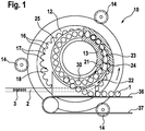
- a device 10 is shown, which is used for separating and embossing of candy 1 from a rolled and drawn, in particular filled with a liquid or semi-liquid filling material 3 strand 2.
- the candies 1 are so-called caramels, even though the apparatus 10 shown can also be used for forming any other confectionery including chewing gum pieces.
- the device 10 has a first, outer separating ring or knife ring 12, which cooperates with a second, inner separating ring 13.
- the outer separator ring 12 is mounted on its outer circumference by means of three rollers 14.
- the outer separator ring 12 has on its inner circumferential surface semi-circular shaped mold cavities 16 which adjoin one another directly.
- dividers 17 formed, which extend over the entire width of the corresponding mold cavities 16. The separating webs 17 are used to separate the candy 1 from the mass strand 2, to which the dividing webs 17 have cut edges 18.
- the inner separator ring 13 is mounted eccentrically within the outer separator ring 12 and is driven by a non-illustrated drive also counterclockwise continuously.
- the inner separator ring 13 also has half round mold cavities 21 which cooperate with the mold cavities 16 of the outer separator ring 12 during circulation of the inner separator ring 13.
- the diameter, the rotational speed and the arrangement of the mold cavities 21 of the inner separator ring 13 are so matched to the outer separator ring 12, that in a circulation of the two separator rings 12, 13 of in a region 22 between the two separator rings 12, 13 supplied strand 2 at an approximation of the two separating rings 12, 13 and the corresponding mold cavities 16, 21 device in the area between the mold cavities 16, 21.
- the inner separator ring 13 has in the transition region between its mold cavities 21 also dividers 23 with cut edges 24, the shape of the cut edges 18 of the outer separator ring 12 is adjusted.
- the opposite cut edges 18, 24 of the respective dividing webs 17, 23 come into contact, the candies 1 are separated as a single piece of the mass strand 2 completely.
- a coaxially arranged embossing chamber ring 25 which is embodied here in one piece with the inner separating ring 13.
- the embossing chamber ring 25 has embossing chambers 30 designed as through-holes, which are aligned with the mold cavities 21 of the inner separating ring 13. On both sides of this parallel to the axis of rotation of the embossing chamber 25 arranged on both sides open embossing 25 embossing dies 31, 32 are provided for embossing a separated from the strand 2 candy, each two a die pair 33 forming die 31, 32 are aligned with one of the embossing chambers 30 and in these are displaceable.
- the dies 31, 32 driven by a cam control and perpendicular to the plane of the FIG. 1 during rotation of the inner separating ring 13 movable.
- the dies 31, 32 On the partitions 23 facing side, the dies 31, 32 have a curved shape, which is adapted to the desired embossing or shaping of the candy 1.
- the co-operating stamping dies 31, 32 are each guided along a cam track 41, 42, the course over a part of the circumferential angle closer in FIG. 4 is shown.
- the curved path 41, 42 is in each case predetermined by a guide element 43 or 44.
- the guide member 43 of a first punch 31 of the die pair 33 is formed as a swash plate 43, which performs a sinusoidal wobbling motion during its rotation and in the present case is mounted pneumatically sprung in the axial direction.
- the swash plate 43 is connected transversely displaceably to the associated stamping die 31 or an embossing stamp shank 31A extending along a longitudinal axis of the stamping stamp 31 by means of a ball joint 34.
- the opposite die 32 of the die pair 33 is guided by a ring member 45, 46 guide member 44, said ring body 45, 46 are fixed and with their contour on the circumference and their axial distance from one another forming a slideway representing cam track 42 in which the die 32 of the die pair 33 slides.
- the embossing die 32 is here in the curved path 42 between the annular bodies 45 and 46, of which the closer to the embossing chamber ring 25 arranged ring body 45 a retreating curve of the further away from the embossing chamber ring 25 arranged annular body 46 a pressure curve for the die 32 in the region of the cam track 42nd forms, guided by a guide roller 48.
- the guide roller 48 is mounted on an axle element 49 which projects away from a stamping shaft 32A perpendicular to a longitudinal axis of the stamping punch 32.
- the dies 31, 32 of each die pair 33 are first moved from a retracted position against the associated embossing chamber 30, wherein the outer Separating ring 12 crossing, ring-body-side die 32 introduces one of the dividing webs 17, 23 detached from the strand 2 blank of a single piece 1 of a candy in the embossing chamber 30, in each of which a die pair 33 the single piece 1 pressed from two sides.
- the swashplate-side embossing punch 31 After the pressing operation, the swashplate-side embossing punch 31 returns to its starting position, while the opposite embossing punch 32 is driven further, so that it ejects the ready-formed candy 1 from the embossing chamber 30. When ejected from the embossing chamber 30, the candy finally reaches a conveying run 36 of a continuously driven conveyor 37 in the lower region of the device 10.
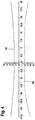
- FIG. 4 which shows a punch distance D in millimeters over the insert rotation angle or circumference angle ⁇
- the coordination of the cam tracks 41, 42 to each other apparent which are designed so that in a rotation about an axis of the associated the cam track 41, 42 predetermining guide element 43 and 44 as a result of an approach of the dies 31, 32 the embossing of the single piece or candy 1 in a circumferential angle range of at least approximately 12 ° to 15 ° before a point D_min minimum distance between the dies 31, 32 begins and ends in a circumferential angle range of at least approximately 0 ° to 15 ° after the point D_min minimum distance between the dies.
- Embossing is understood to be the final shaping of a candy 1, in which the distance difference D between the stamping dies 31, 32 over the circumferential angle ⁇ between the point of commencement of the embossing of the candy 1 and the point D_min minimum distance between the embossing dies 31, 32 between 0 , 1 mm and 0.7 mm.
- the distance difference D between the stamping dies 31, 32 during the embossing phase is between 0.3 mm and 0.5 mm.
- the point D_min minimum distance between the stamping dies 31, 32 is in the present embodiment about 5 ° after a vertex or a 12 o'clock position of the swash plate 43 in a region of least relative movement.
- the candy 1 is thereby embossed symmetrically about the vertex of the swash plate in order to avoid that the candy 1 is pushed under pressure in the embossing chamber 30 and thereby may possibly stick.
- the aim of the cam guide is to bypass the apex of the swash plate 43 as close as possible and to use a relatively quiet position of the tumbling side punch 31, which is why an asymptotic approximation of the ring body side punch 32 is selected symmetrically to the apex of the swash plate 43.
- an optimum pressure force curve during the embossing process is set within a range of approximately +/- 7.5 ° about the vertex of the swash plate 43, wherein a lifting of the swash plate 43 is prevented against the elastic bias due to local force peaks.
Landscapes
- Engineering & Computer Science (AREA)
- Life Sciences & Earth Sciences (AREA)
- Chemical & Material Sciences (AREA)
- Food Science & Technology (AREA)
- Polymers & Plastics (AREA)
- Mechanical Engineering (AREA)
- Confectionery (AREA)
- Adornments (AREA)
Description
Die Erfindung betrifft eine Vorrichtung zum Formen von aus einem Massestrang gefertigten Waren, insbesondere bonbonartigen Süßwaren, nach der im Oberbegriff des Patentanspruches 1 näher definierten Art.The invention relates to a device for molding made of a mass strand goods, especially candy-type confectionery, according to the closer defined in the preamble of
Eine derartige Vorrichtung ist aus der
Seitlich des Prägekammerringes sind zwei zueinander exzentrisch umlaufende, sich aufeinander abwälzende Trennringe vorgesehen, deren jeder mit messerartigen Trennstegen und mit dazwischen ausgebildeten Halbformmulden auf seiner dem anderen zugekehrten Umfangseite versehen ist, wobei die Halbformmulden eines der Trennringe gleichachsig mit den Prägekammern des Prägekammerrings ausgerichtet sind. Die Trennstege dienen zum Abtrennen von Einzelstücken von dem Massestrang. Das Abtrennen erfolgt dabei bei einer Annäherung der beiden Trennringe während ihres Umlaufs, wobei der Massestrang zwischen den beiden Trennringen geführt ist. Nach dem Abtrennen der Einzelstücke werden diese von den Formmulden aufgenommen und geformt. Beim weiteren Umlauf der Trennringe werden die vorgeformten Bonbons mittels der Prägestempel in die als Durchgangsbohrungen ausgebildeten Prägekammern des Prägekammerrings verschoben, wo das Prägen der Bonbons mittels der gegeneinander bewegten Prägestempel stattfindet. Anschließend werden die geprägten Bonbons mittels der Prägestempel auf eine Fördereinrichtung ausgeworfen.The side of the embossing chamber ring two mutually eccentrically encircling, mutually rolling separating rings are provided, each of which is provided with knife-like dividers and formed therebetween Halbformmulden on its other circumferential side, the Halbformmulden one of the separating rings are aligned coaxially with the embossing chambers of the embossing chamber ring. The dividers are used to separate individual pieces of the mass strand. The separation takes place at an approach of the two separating rings during their circulation, wherein the mass strand is guided between the two separating rings. After separating the individual pieces they are taken up and shaped by the mold cavities. During the further circulation of the separating rings, the preformed candies are moved by means of the embossing stamp into the embossing chamber rings formed as through-holes, where the embossing of the candies takes place by means of the embossing dies moved relative to each other. Subsequently, the embossed candies are ejected by means of the die on a conveyor.
In der Praxis werden die Prägestempel über eine Kurvensteuerung axial in Richtung der Trennringe und des Prägekammerringes bewegt oder von diesen wegbewegt, wobei an einem Punkt mit minimalem Abstand zwischen den Prägestempeln eine Prägekraft von einer Druckrolle mittels einer Stoßbewegung auf einen der Prägestempel aufgebracht wird. Danach fährt einer der Prägestempel wieder in seine Ausgangsstellung zurück und das Bonbon wird durch den anderen Prägestempel aus der Prägekammer geschoben und somit auf die Fördereinrichtung ausgeworfen. Hiernach fährt auch der das Auswerfen des Bonbons bewirkende Prägestempel wieder in seine Ausgangsstellung hinter den Trennringen zurück.In practice, the dies are moved axially in the direction of the separating rings and the embossing chamber ring by a cam control or moved away therefrom, wherein a stamping force is applied to one of the stamping dies by a pushing roller at a point with minimum spacing between the stamping dies. Then one of the dies moves back to its original position and the candy is removed from the stamping chamber by the other die pushed and thus ejected onto the conveyor. After that, the embossing punch that effects the ejection of the candy also returns to its original position behind the separating rings.
Von Praxisbeispielen ist es bekannt, die Kurvensteuerung für einen der Prägestempel mit einem topfartigen Körper zu realisieren, in dessen Umfangswandung die Kurvenbahn als Ausnehmung eingebracht ist. In dieser Kurvenbahn wird der zugeordnete Prägestempel, welcher mit dem Prägekammerring umläuft, bei seiner Umlaufbewegung mittels einer Kurvenrolle geführt, wobei im Bereich einer maximalen Verschiebung entgegen der Prägekammer Spielraum für eine Stoßbewegung seitens der Druckrolle in Richtung der Prägekammer gegeben ist.From practical examples, it is known to realize the cam control for one of the dies with a pot-like body, in the peripheral wall of the curved path is introduced as a recess. In this curved path of the associated die, which rotates with the embossing chamber ring, guided in its orbital movement by means of a cam roller, being given in the region of maximum displacement against the embossing chamber scope for a thrust movement on the part of the pressure roller in the direction of the embossing chamber.
Der gegenüberliegende Prägestempel wird bei aus der Praxis bekannten Anwendungsbeispielen mittels eines Taumelscheibenantriebs geführt, wobei die Kurvensteuerung des Prägestempels durch die Taumelbewegung der mit dem Prägestempel über ein Kugelgelenk verbundenen Taumelscheibe realisiert ist.The opposite die is performed in practice known application examples by means of a swash plate drive, wherein the curve control of the embossing stamp is realized by the tumbling motion of the associated with the die through a ball joint swash plate.
Nachteilhafterweise führt bei den bekannten Vorrichtungen bei hohen Prägegeschwindigkeiten die Stoßbelastung über die Druckrolle auf den angrenzenden Prägestempel zu sehr starken dynamischen Belastungen des Gesamtsystems. Über den Kraftfluss durch das zu prägende Bonbon auf die in der Regel pneumatisch vorgespannte Taumelscheibe wird die gesamte Apparatur in Schwingungen versetzt. Der Verschleiß, insbesondere an den Kurvenrollen und den Kurvenbahnen, ist während des Stoßes und beim Wiedereinfädeln der Kurvenrolle in die Kurvenbahn beträchtlich. Des Weiteren limitieren die dynamischen Stoßbelastungen die Rotationsgeschwindigkeit und somit die Ausstoßleistung der jeweiligen Vorrichtung und führen darüber hinaus zu sehr hohen Schallpegeln bei einem Prägevorgang.Disadvantageously, in the known devices at high embossing speeds, the impact load on the pressure roller on the adjacent die leads to very strong dynamic loads of the overall system. Through the flow of power through the candy to be embossed onto the generally pneumatically preloaded swash plate, the entire apparatus is set in vibration. The wear, especially on the cam rollers and the cam tracks, is during the impact and when re-threading the cam roller in the curved path considerably. Furthermore, the dynamic impact loads limit the rotational speed and thus the output of the respective device and also lead to very high sound levels in a stamping process.
Die
Es ist somit Aufgabe der vorliegenden Erfindung, eine Vorrichtung der eingangs genannten Art dahingehend weiterzubilden, dass insbesondere der Verschleiß vermindert und die Prägeleistung der Vorrichtung erhöht wird.It is therefore an object of the present invention to develop a device of the type mentioned in that in particular reduces the wear and the embossing performance of the device is increased.
Die erfindungsgemäße Vorrichtung zum Formen von aus einem Massestrang gefertigten Waren, insbesondere bonbonartigen Süßwaren, mit den Merkmalen des Anspruches 1 hat den Vorteil, dass sich die Prägung über einen vergleichsweise großen Umfangswinkel und somit über eine längere Zeitspanne erstreckt, so dass die hochviskose Masse des Einzelstückes mit geringerer Verformungsgeschwindigkeit und mit geringerem Kraftaufwand geformt werden kann.The device according to the invention for molding goods made of a mass strand, in particular candy-type confectionery, with the features of
Ein optimaler Prägeverlauf stellt sich dabei ein, wenn die Kurvenbahnen, entlang derer jeweils die Prägestempel eines Prägestempelpaares bei einem Umlauf um eine Achse eines zugeordneten, die Kurvenbahn eines Prägestempels vorgebenden Führungselementes bewegt werden, derart zueinander festgelegt sind, dass im Betrieb bei einem Umlauf in Folge einer Annäherung der Prägestempel die Prägung des Einzelstückes in einem Umfangswinkelbereich von wenigstens annähernd 12° bis 15° vor einem Punkt minimalen Abstandes zwischen den Prägestempeln beginnt und in einem Umfangswinkelbereich von wenigstens annähernd 0° bis 5° nach dem Punkt minimalen Abstandes zwischen den Prägestempeln endet.An optimal embossing occurs when the curved paths, along which the dies of a die pair are moved in a rotation about an axis of an associated, the cam track of a punch indicative guide element, are fixed to each other in such a way that during operation in a cycle in sequence an approach the embossing die begins embossing the single piece in a circumferential angular range of at least approximately 12 ° to 15 ° before a point of minimum distance between the dies and terminates within a circumferential angular range of at least approximately 0 ° to 5 ° from the minimum distance between the dies.
Durch die spezielle Abstimmung des Verlaufes der Kurvenbahnen zueinander im Hinblick auf einen optimalen Druckkraftverlauf während des Prägevorganges kann die Prägung ohne die Aufbringung einer Stoßkraft beispielsweise seitens einer Druckrolle durchgeführt werden, womit vorteilhafterweise nicht nur die Bauteilvielzahl reduziert wird, sondern auch eine Störung der Kurvenbahn im Bereich einer Druckrolle und die von dieser ausgehenden verschleiß- und schallwirksamen dynamischen Kräfte vermieden werden. Da der Prägevorgang bei einer erfindungsgemäß ausgestalteten Vorrichtung ohne dynamische Stoßbelastungen erfolgt, können Schwingungen in der Vorrichtung vermieden werden und höhere Prägeleistungen bei gleicher Belastung erzielt werden.Due to the special vote of the course of the cam tracks to each other with respect to an optimal pressure force curve during the embossing process, the embossing can be performed without the application of an impact force, for example, by a pressure roller, which advantageously not only the number of components is reduced, but also a disturbance of the curved path in the area a pressure roller and emanating from this wear and sound dynamic forces are avoided. Since the embossing process takes place in a device designed according to the invention without dynamic impact loads, vibrations in the device can be avoided and higher embossing performances can be achieved with the same load.
Bei einer besonders vorteilhaften Ausführung der erfindungsgemäßen Vorrichtung weist das Führungselement wenigstens der auf einer Seite der Prägekammern angeordneten Prägestempel feststehende Ringkörper auf, deren Kontur und axialer Abstand zueinander die Kurvenbahn hierin geführter Prägestempel bildet.In a particularly advantageous embodiment of the device according to the invention, the guide element has at least fixed on one side of the embossing dies stamped annular body, the contour and axial distance from one another forms the curved track guided here punch.
Derartige Ringkörper, welche auch eine Art Topf bilden können, ermöglichen eine kostengünstige und robuste Realisierung einer Kurvenbahn als Gleitbahn, wobei es vorteilhaft ist, wenn ein Prägestempel in der Kurvenbahn mittels einer Führungsrolle geführt ist, welche an einem Achselement gelagert ist, welches im Wesentlichen senkrecht zu einer Längsachse des Prägestempel von einem Prägestempelschaft wegkragt.Such ring body, which can also form a kind of pot, allow a cost-effective and robust realization of a curved path as a slide, it is advantageous if an embossing die is guided in the curved path by means of a guide roller which is mounted on an axle, which is substantially perpendicular wegkragt to a longitudinal axis of the stamper of a die shaft.
Grundsätzlich können zur Führung beider Prägestempel eines Prägestempelpaares, von denen in der Regel eine Vielzahl trommelartig in einem Kreis um eine Drehachse des Führungselementes angeordnet ist, auf beiden Seiten der Prägekammern Führungselemente vorgesehen seien, die die entsprechende Kurvenbahn durch feststehende Ringkörper bilden.In principle, guide elements can be provided on both sides of the embossing chambers for guiding both embossing dies of an embossing die pair, of which a plurality is arranged in a drum-like manner in a circle about an axis of rotation of the guide element, which form the corresponding curved path through fixed annular bodies.
In einer vorteilhafter Ausgestaltungsvariante ist das Führungselement der auf einer der Seiten der Prägekammern angeordneten Prägestempel mit feststehenden Ringkörpern ausgebildet und das Führungselement der auf der anderen Seite der Prägekammern angeordneten Prägestempel als eine Taumelscheibe ausgebildet.In an advantageous embodiment variant, the guide element of the embossing dies arranged on one of the sides of the embossing chambers is formed with fixed annular bodies, and the guide element of the embossing dies arranged on the other side of the embossing chambers is designed as a swashplate.
Der Einsatz einer solchen Taumelscheibe hat sich in der Praxis bewährt, wobei die Taumelscheibe vorzugsweise federnd gelagert ist und beispielsweise eine pneumatische Vorspannung aufweist, so dass diese bei einer zu starken Befüllung der Prägekammer dem hier seitens der Prägekammer ausgeübten Druck nachgeben kann.The use of such a swash plate has proven itself in practice, wherein the swash plate is preferably resiliently mounted and, for example, has a pneumatic bias, so that it can yield to an excessive filling of the embossing chamber here exerted by the embossing chamber pressure.
Die Führung von Prägestempeln mittels einer in der Regel eine Sinuskurve beschreibenden Taumelscheibe ist auf einfache Art und Weise möglich, indem ein Prägestempelschaft über ein Kugelgelenk mit der Taumelscheibe drehbar verbunden wird.The guide of stamping by means of a generally describing a sine wave descriptive swash plate is possible in a simple manner by a punch shaft is rotatably connected via a ball joint with the swash plate.
Zur Erzielung eines hochwertigen Prägeergebnisses können die Kurvenbahnen der beiderseitigen Führungselemente derart vorgegeben sein, dass die Abstandsdifferenz zwischen den Prägestempeln über den Umfangswinkel zwischen dem Punkt des Beginns der Prägung des von dem Massestrang abgetrennten Einzelstückes und dem Punkt minimalen Abstandes zwischen den Prägestempeln in einem Bereich von 0,1 mm und 0,7 mm, insbesondere zwischen 0,3 mm und 0,5 mm, liegt.To obtain a high-quality embossing result, the curved paths of the mutual guide elements can be predetermined such that the distance difference between the stamping dies exceeds the circumferential angle between the point of commencement of the embossing of the single piece separated from the strand of material and the point of minimum distance between the embossing dies in a range of 0 , 1 mm and 0.7 mm, in particular between 0.3 mm and 0.5 mm.
Weitere Vorteile und vorteilhafte Ausgestaltungen des Gegenstandes nach der Erfindung sind der Beschreibung, der Zeichnung und den Patentansprüchen entnehmbar.Further advantages and advantageous embodiments of the article according to the invention are the description, the drawings and the claims removed.
Ein Ausführungsbeispiel des erfindungsgemäßen Gegenstandes ist in der Zeichnung schematisch vereinfacht dargestellt und wird in der nachfolgenden Beschreibung näher erläutert. Es zeigen:
-
Figur 1 -
Figur 2Figur 1 -
Figur 3Figur 1 -
Figur 4
-
FIG. 1 a device according to the invention for embossing made of a mass strand candy or the like in a simplified cross-section; -
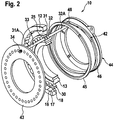
FIG. 2 a simplified perspective view of individual elements of the device ofFIG. 1 ; -
FIG. 3 a plan view of a section of a curved path with a cam roller of a stamping die of the deviceFIG. 1 ; and -
FIG. 4 a diagram showing the distance between the embossing stamp pair forming embossing dies in a stamping process.
In den Figuren ist eine Vorrichtung 10 dargestellt, welche zum Abtrennen und Prägen von Bonbons 1 von einem ausgewalzten und ausgezogenen, insbesondere mit einem flüssigen oder halbflüssigen Füllgut 3 gefüllten Massestrang 2 dient. Bei den Bonbons 1 handelt es sich vorliegend um so genannte Karamellen, gleich die gezeigte Vorrichtung 10 auch zum Formen jedweder anderer Süßwaren einschließlich Kaugummistücken Anwendung finden kann.In the figures, a
Wie besonders deutlich der
Der innere Trennring 13 ist exzentrisch innerhalb des äußeren Trennringes 12 gelagert und wird mittels eines nicht näher dargestellten Antriebes ebenfalls im Gegenuhrzeigersinn kontinuierlich angetrieben. Der innere Trennring 13 weist ebenfalls halbrund ausgebildete Formmulden 21 auf, die beim Umlauf des inneren Trennrings 13 mit den Formmulden 16 des äußeren Trennrings 12 zusammenwirken. Der Durchmesser, die Drehzahl sowie die Anordnung der Formmulden 21 des inneren Trennrings 13 sind derart auf den äußeren Trennring 12 abgestimmt, dass bei einem Umlauf der beiden Trennringe 12, 13 der in einen Bereich 22 zwischen die beiden Trennringe 12, 13 zugeführte Massestrang 2 bei einer Annäherung der beiden Trennringe 12, 13 sowie der entsprechenden Formmulden 16, 21 in den Bereich zwischen die Formmulden 16, 21 gerät.The
Der innere Trennring 13 weist im Übergangsbereich zwischen seinen Formmulden 21 ebenfalls Trennstege 23 mit Schnittkanten 24 auf, deren Form den Schnittkanten 18 des äußeren Trennrings 12 angepasst ist. In Folge der Annäherung der beiden Trennringe 12, 13 bei deren Umlauf geraten die einander gegenüber liegenden Schnittkanten 18, 24 der jeweiligen Trennstege 17, 23 in Kontakt, wobei die Bonbons 1 als Einzelstücke von dem Massestrang 2 vollständig abgetrennt werden. An den inneren Trennring 13 schließt sich seitlich ein koaxial angeordneter Prägekammerring 25 an, welcher hier einstückig mit dem inneren Trennring 13 ausgeführt ist.The
Der Prägekammerring 25 weist als Durchgangsbohrungen ausgebildete Prägekammern 30 auf, welche mit den Formmulden 21 des inneren Trennrings 13 fluchten. Beidseits dieser parallel zur Drehachse des Prägekammerrings 25 angeordneten, beidseitig offenen Prägekammern 25 sind zum Prägen eines von dem Massestrang 2 abgetrennten Bonbons 1 Prägestempel 31, 32 vorgesehen, wobei je zwei ein Prägestempelpaar 33 bildende Prägestempel 31, 32 zu einer der Prägekammern 30 fluchten und in diese verschiebbar sind.The
Wie die
Die paarweise zusammenwirkenden Prägestempel 31, 32 werden jeweils entlang einer Kurvenbahn 41, 42 geführt, deren Verlauf über einen Teil des Umfangwinkels näher in
Wie die exemplarische Darstellung eines Prägestempelpaares 33 von insgesamt 35 bei der gezeigten Ausführung vorhandenen Prägestempelpaaren in
Der gegenüberliegende Prägestempel 32 des Prägestempelpaares 33 wird von einem durch Ringkörper 45, 46 gebildeten Führungselement 44 geführt, wobei diese Ringkörper 45, 46 feststehen und mit ihrer Kontur am Umfang sowie ihrem axialen Abstand zueinander die eine Gleitbahn darstellende Kurvenbahn 42 ausbilden, in der der Prägestempel 32 des Prägestempelpaares 33 gleitet. Der Prägestempel 32 ist hierbei in der Kurvenbahn 42 zwischen den Ringkörpern 45 und 46, von denen der näher an dem Prägekammerring 25 angeordnete Ringkörper 45 eine Rückstreifkurve der weiter entfernt von dem Prägekammerring 25 angeordnete Ringkörper 46 eine Druckkurve für den Prägestempel 32 im Bereich der Kurvenbahn 42 bildet, mittels einer Führungsrolle 48 geführt. Die Führungsrolle 48 ist an einem Achselement 49 gelagert, welches senkrecht zu einer Längsachse des Prägestempels 32 von einem Prägestempelschaft 32A wegkragt.The opposite die 32 of the
Entlang der Kurvenbahnen 41, 42, welche mit axial vor- und zurückweichenden Bereichen die axiale Verschiebebewegung der Prägestempel 31, 32 steuern, werden die Prägestempel 31, 32 jedes Prägestempelpaares 33 zunächst aus einer zurückgezogenen Stellung gegen die zugehörige Prägekammer 30 bewegt, wobei der den äußeren Trennring 12 querende, ringkörperseitige Prägestempel 32 einen von den Trennstegen 17, 23 vom Massestrang 2 abgetrennten Rohling eines Einzelstückes 1 eines Bonbons in die Prägekammer 30 einbringt, in der jeweils ein Prägestempelpaar 33 das Einzelstück 1 von zwei Seiten verpresst.Along the cam tracks 41, 42 which control the axial displacement movement of the dies 31, 32 with axially projecting and receding areas, the dies 31, 32 of each die
Nach dem Pressvorgang kehrt der taumelscheibenseitige Prägestempel 31 in seine Ausgangsstellung zurück, während der gegenüberliegende Prägestempel 32 noch weiter vorgetrieben wird, so dass er das fertig geformte Bonbon 1 aus der Prägekammer 30 auswirft. Beim Auswurf aus der Prägekammer 30 gelangt das Bonbon schließlich auf ein Fördertrum 36 einer kontinuierlich angetriebenen Fördereinrichtung 37 im unteren Bereich der Vorrichtung 10.After the pressing operation, the swashplate-
Besonders anhand des Diagramms der
Als Prägen wird dabei die Endformung eines Bonbons 1 verstanden, bei dem die Abstandsdifferenz D zwischen den Prägestempeln 31, 32 über den Umfangswinkel ϕ zwischen dem Punkt des Beginns der Prägung des Bonbons 1 und dem Punkt D_min minimalen Abstandes zwischen den Prägestempeln 31, 32 zwischen 0,1 mm und 0,7 mm betragen kann. Bei der gezeigten Ausführung beträgt die Abstandsdifferenz D zwischen den Prägestempeln 31, 32 während der Prägephase zwischen 0,3 mm und 0,5 mm.Embossing is understood to be the final shaping of a
Der Punkt D_min minimalen Abstandes zwischen den Prägestempeln 31, 32 liegt bei der vorliegenden Ausführung circa 5° nach einem Scheitelpunkt bzw. einer 12-Uhr-Stelle der Taumelscheibe 43 in einem Bereich geringster Relativbewegung. Das Bonbon 1 wird dabei symmetrisch um den Scheitelpunkt der Taumelscheibe geprägt, um zu vermeiden, dass das Bonbon 1 unter Druck in der Prägekammer 30 geschoben wird und hierdurch gegebenenfalls ankleben kann. Ziel der Kurvenführung ist es, den Scheitelpunkt der Taumelscheibe 43 so dicht wie möglich zu umgehen und eine vergleichsweise ruhige Lage des taumelseitigen Prägestempels 31 zu nutzen, weshalb hier eine asymptotische Annäherung des ringkörperseitigen Prägestempels 32 symmetrisch zum Scheitelpunkt der Taumelscheibe 43 gewählt ist.The point D_min minimum distance between the stamping dies 31, 32 is in the present embodiment about 5 ° after a vertex or a 12 o'clock position of the
Bei dem gezeigten Prägeverlauf, bei dem der ringkörperseitige Prägestempel 32 bereits zwischen -10° und -5° so nah gegen den taumelscheibenseitigen Prägestempel 31 geführt wird, dass das Bonbon 1 bereits geformt wird, bei dem zwischen -7,5° und +7,5° die Kurvenbahn 42 des ringkörperseitigen Prägestempels 32 der Kurvenbahn 41 des taumelscheibenseitigen Prägestempels 31 folgt, und bei dem bei +5° der Punkt D minimalen Abstandes zwischen den Prägestempeln 31, 32 und das Ende der Prägung erreicht ist, wird durch den langen Winkelweg und den Kurvenverlauf die Formungsgeschwindigkeit des Bonbons 1 immer weiter verringert, damit mit möglichst konstanter Verformungskraft über einen großen Prägebereich von circa 15° das Bonbon 1 fertig geprägt werden kann. Die gesamte Verformungskraft für das Ausprägen des Bonbons 1 zwischen den Prägestempeln 31, 32 wird dabei über deren Führung entlang der Kurvenbahnen 41, 42 ohne zusätzliche Stoßbewegung aufgebracht.In the embossing process shown, in which the ring-body-
Es wird somit ein optimaler Druckkraftverlauf während des Prägevorgangs innerhalb eines Bereichs von circa +/-7,5° um den Scheitelpunkt der Taumelscheibe 43 eingestellt, wobei ein Abheben der Taumelscheibe 43 gegen die elastische Vorspannung aufgrund lokaler Kraftspitzen verhindert wird.Thus, an optimum pressure force curve during the embossing process is set within a range of approximately +/- 7.5 ° about the vertex of the
Nachdem in dem Punkt D_min minimalen Abstandes zwischen den Prägestempeln 31, 32 ein sogenannter Prägepunkt erreicht wird, entfernen sich bei weiterem Umlauf der Trennringe 12, 13 die Prägestempel 31, 32 voneinander, wobei der taumelscheibenseitige Prägestempel 31 entlang der Kurvenbahn 42 in seine Ausgangsstellung zurückgefahren wird und der ringkörperseitige Prägestempel 32 das Auswerfen des Bonbons 1 aus dem Prägekammerring 30 annähernd an einer 8-Uhr-Stelle der Taumelscheibe 43 bewirkt, bevor auch dieser Prägestempel 32 wieder in seine Ausgangsstellung hinter den Trennringen 12, 13 zurückgezogen wird.After a so-called embossing point is reached in the point D_min minimum distance between the stamping dies 31, 32, the dies 31, 32 move away from each other as the separating rings 12, 13 rotate, the stamping die 31 along the
Claims (3)
- Device for shaping products, in particular confectionery-type sweets, made from a mass strand (2), having two mutually eccentrically revolving annular separators (12, 13), each thereof having troughs (16, 21) and separation webs (17, 23), wherein the separation webs (17, 23) converge as the annular separators (12, 13) revolve and contact individual pieces (1) so as to separate the latter from the mass strand (2), and having a revolving annular embossing chamber (25) having embossing chambers (30) that are open towards both sides and in each of which, for embossing a severed individual piece (1), two embossing tools (31, 32) that are disposed on either side of an embossing chamber (30) so as to form one embossing-tool pair (33) are displaceable, wherein the embossing tools (31, 32) each are driven by means of a cam control, wherein the cam tracks (41, 42) along each of which the embossing tools (31, 32) of an embossing-tool pair (33) are moved when revolving about an axis of an assigned guide element (43, 44) that defines the cam track (41, 42) are mutually fixed in such a manner that in the case of one revolution, as a result of a convergence of the embossing tools (31, 32), embossing of an individual piece (1) commences in a circumferential angular range of at least approximately 12° to 15° ahead of a point (D_min) of a minimum spacing between the embossing tools (31, 32) and terminates in a circumferential angular range of at least approximately 0° to 5° behind the point (D_min) of minimum spacing between the embossing tools (31, 32), wherein the guide element (44) of at least the embossing tools (32) that are disposed on one side of the embossing chambers (30) has stationary annular bodies (45, 46) of which the contour and the mutual axial spacing form the cam track (42) of embossing tools (32) that are guided hereto, characterized in that an embossing tool (32) in the cam track (42) is guided by means of a guide roller (48) which is mounted on an axle element (49) which protrudes from an embossing-tool shaft (32A) in a substantially perpendicular manner to a longitudinal axis of the embossing tool (32), wherein the guide element of the embossing tools (31) that are disposed on one of the sides of the embossing chambers (30) is configured as a swashplate (43), wherein the point (D_min) of minimum spacing between the embossing tools (31, 32) lies at least approximately 5° behind an apex of the swashplate (43), wherein embossing is performed without applying an impact force, for example by a pressure roller, in that the embossing tool (32) in the cam track (42) between the annular body (45, 46), of which the annular body (45) that is proximate to the annular embossing chamber (25) forms a relief curve, and the annular body (46) that is distal from the annular embossing chamber (25) forms a compression curve for the embossing tool (32) in the region of the cam track (42), by means of which cam track the guide roller (48) is guided.
- Device according to Claim 1, characterized in that the swashplate (43) is connected to an embossing tool (31) by means of a ball joint (34).
- Device according to one of Claims 1 to 2, characterized in that the cam tracks (41, 42) are defined in such a manner that the spacing differential (D) between the embossing tools (31, 32) across the circumferential angle (6) between the point of commencement of embossing of the individual piece (1), and the point (D_min) of minimum spacing between the embossing tools (31, 32), is between 0.1 mm and 0.7 mm, in particular between 0.3 mm and 0.5 mm.
Applications Claiming Priority (2)
| Application Number | Priority Date | Filing Date | Title |
|---|---|---|---|
| DE102005018077A DE102005018077A1 (en) | 2005-04-19 | 2005-04-19 | Device for forming goods made of a mass strand |
| PCT/EP2006/060818 WO2006111442A1 (en) | 2005-04-19 | 2006-03-17 | Shaping device for producing goods from a material strand |
Publications (2)
| Publication Number | Publication Date |
|---|---|
| EP1874529A1 EP1874529A1 (en) | 2008-01-09 |
| EP1874529B1 true EP1874529B1 (en) | 2017-03-08 |
Family
ID=36441995
Family Applications (1)
| Application Number | Title | Priority Date | Filing Date |
|---|---|---|---|
| EP06708792.4A Ceased EP1874529B1 (en) | 2005-04-19 | 2006-03-17 | Shaping device for producing goods from a material strand |
Country Status (6)
| Country | Link |
|---|---|
| US (1) | US20090123586A1 (en) |
| EP (1) | EP1874529B1 (en) |
| CN (1) | CN100553959C (en) |
| BR (1) | BRPI0609110A2 (en) |
| DE (1) | DE102005018077A1 (en) |
| WO (1) | WO2006111442A1 (en) |
Families Citing this family (4)
| Publication number | Priority date | Publication date | Assignee | Title |
|---|---|---|---|---|
| DE102007012308A1 (en) | 2007-03-14 | 2008-09-18 | Robert Bosch Gmbh | Device for molding goods made from a mass strand |
| EP2279668B1 (en) * | 2009-07-29 | 2014-07-16 | GEA Food Solutions Weert B.V. | Candy moulding machine |
| CN109592105B (en) * | 2018-12-29 | 2024-06-21 | 成都三可实业有限公司 | Sugar clamping mechanism for granular candy packaging |
| CN111570691B (en) * | 2020-05-13 | 2021-08-13 | 安徽中志轨道交通装备制造有限公司 | Forging mechanism for continuously forging and pressing switch rail and preparation process of forged and pressed switch rail |
Citations (2)
| Publication number | Priority date | Publication date | Assignee | Title |
|---|---|---|---|---|
| DE1180234B (en) * | 1959-11-16 | 1964-10-22 | Carle & Montanari Spa | Candy stamping machine |
| GB1398798A (en) * | 1972-04-18 | 1975-06-25 | Aquarius C | Apparatus for moulding lollipops |
Family Cites Families (13)
| Publication number | Priority date | Publication date | Assignee | Title |
|---|---|---|---|---|
| DE565952C (en) * | 1929-03-24 | 1932-12-09 | Erwin Roemer & Co G M B H | Candy embossing device |
| US1920445A (en) * | 1932-07-26 | 1933-08-01 | Thurlings Hermann | Machine for stamping soft kneadable masses into bon-bons and the like |
| FR1138867A (en) * | 1954-11-27 | 1957-06-20 | Press for the production of tablets | |
| US2865311A (en) * | 1956-11-17 | 1958-12-23 | Hansella Werke Albert Henkel A | Candy making machine |
| FR1166245A (en) * | 1956-11-17 | 1958-11-04 | Hansella Werke Albert Henkel A | Candy stamping machine |
| FR1442374A (en) * | 1965-04-16 | 1966-06-17 | Carle & Montanari Spa | Rotary drum machine for the die-forging of stamped, hard or filled candies |
| DE1627903C3 (en) * | 1967-10-20 | 1979-03-29 | Gerhard Dipl.-Ing. 4930 Detmold Roemer | Press for compacting fibrous lining materials |
| DE2456480C3 (en) * | 1974-11-29 | 1978-07-20 | Robert Bosch Gmbh, 7000 Stuttgart | Device for embossing sweets |
| IT1095200B (en) * | 1978-06-07 | 1985-08-10 | Carle & Montanari Spa | ROTARY DRUM MOLD, IN PARTICULAR FOR THE PRODUCTION OF CANDIES |
| US4453300A (en) * | 1982-03-22 | 1984-06-12 | Borg-Warner Corporation | Method of manufacturing a swash plate assembly |
| US6284291B1 (en) * | 1999-08-09 | 2001-09-04 | Warner-Lambert Company | Method and apparatus for continuously forming center-filled gum |
| US6472001B1 (en) * | 2000-09-07 | 2002-10-29 | Joseph M. Bunkers | System for continuously forming center filled gum |
| US6838098B2 (en) * | 2000-09-07 | 2005-01-04 | Cadbury Adams Usa, Llc | Continuous formation of center filled gum |
-
2005
- 2005-04-19 DE DE102005018077A patent/DE102005018077A1/en not_active Withdrawn
-
2006
- 2006-03-17 BR BRPI0609110-5A patent/BRPI0609110A2/en not_active IP Right Cessation
- 2006-03-17 US US11/908,433 patent/US20090123586A1/en not_active Abandoned
- 2006-03-17 WO PCT/EP2006/060818 patent/WO2006111442A1/en not_active Application Discontinuation
- 2006-03-17 CN CNB2006800130988A patent/CN100553959C/en not_active Expired - Fee Related
- 2006-03-17 EP EP06708792.4A patent/EP1874529B1/en not_active Ceased
Patent Citations (2)
| Publication number | Priority date | Publication date | Assignee | Title |
|---|---|---|---|---|
| DE1180234B (en) * | 1959-11-16 | 1964-10-22 | Carle & Montanari Spa | Candy stamping machine |
| GB1398798A (en) * | 1972-04-18 | 1975-06-25 | Aquarius C | Apparatus for moulding lollipops |
Also Published As
| Publication number | Publication date |
|---|---|
| CN100553959C (en) | 2009-10-28 |
| BRPI0609110A2 (en) | 2010-02-23 |
| DE102005018077A1 (en) | 2006-10-26 |
| US20090123586A1 (en) | 2009-05-14 |
| WO2006111442A1 (en) | 2006-10-26 |
| EP1874529A1 (en) | 2008-01-09 |
| CN101163583A (en) | 2008-04-16 |
Similar Documents
| Publication | Publication Date | Title |
|---|---|---|
| DE69405010T2 (en) | CIRCULAR TABLETING MACHINE | |
| DE69704928T2 (en) | Method and machine for forging an object with a deformed end part | |
| DE1953838A1 (en) | Powder compaction press | |
| WO2012113615A1 (en) | Apparatus for metering pulverulent filling material | |
| DE2643855C2 (en) | Device for embossing sweets | |
| EP0448190B1 (en) | Rotary press | |
| EP1874529B1 (en) | Shaping device for producing goods from a material strand | |
| DE10142805C2 (en) | One-piece joint body | |
| DE2456480C3 (en) | Device for embossing sweets | |
| EP0917917A1 (en) | Method and device for cold forming of hollow members | |
| DE19936828C2 (en) | Nozzle arrangement, nozzle carrier and device for extruding doughy masses | |
| EP2165785B1 (en) | Method and device for manufacturing longitudinal grooves in cylindrical workpieces | |
| DE2914967C2 (en) | ||
| DE102004059263B4 (en) | Device for forming rotationally symmetrical bodies from a modelable, pasty mass | |
| DE2201521C2 (en) | Molding machine for the production of a selectable number of layers having products from mouldable material, in particular dough products | |
| DE2361161C3 (en) | Apparatus for making a corrugated annular spring | |
| DE19719312C2 (en) | Method and device for the production of, in particular, small metal balls from a cylindrical strand material | |
| EP2529922B1 (en) | Drive device for a press, die cutter or moulding machine | |
| DE2842484C2 (en) | Device for embossing sweets | |
| DE2920814C2 (en) | Rotating press mold, especially for the production of caramels | |
| DE19820103C2 (en) | Forming machine with rotating forming tools | |
| DE505152C (en) | Machine for the production of sweets from a strand of mass | |
| DE2113523C3 (en) | Ejection device on rotary presses for the production of pellets, such as tablets and the like | |
| DE3049276C2 (en) | Briquetting press | |
| DE2919346A1 (en) | Cold forging press for bolts - has dies mounted in rotatable cylinder driven with intermittent motion from crankshaft |
Legal Events
| Date | Code | Title | Description |
|---|---|---|---|
| PUAI | Public reference made under article 153(3) epc to a published international application that has entered the european phase |
Free format text: ORIGINAL CODE: 0009012 |
|
| 17P | Request for examination filed |
Effective date: 20071119 |
|
| AK | Designated contracting states |
Kind code of ref document: A1 Designated state(s): DE ES GB IT |
|
| DAX | Request for extension of the european patent (deleted) | ||
| RBV | Designated contracting states (corrected) |
Designated state(s): DE ES GB IT |
|
| 17Q | First examination report despatched |
Effective date: 20130604 |
|
| GRAP | Despatch of communication of intention to grant a patent |
Free format text: ORIGINAL CODE: EPIDOSNIGR1 |
|
| INTG | Intention to grant announced |
Effective date: 20161213 |
|
| GRAS | Grant fee paid |
Free format text: ORIGINAL CODE: EPIDOSNIGR3 |
|
| GRAA | (expected) grant |
Free format text: ORIGINAL CODE: 0009210 |
|
| AK | Designated contracting states |
Kind code of ref document: B1 Designated state(s): DE ES GB IT |
|
| REG | Reference to a national code |
Ref country code: GB Ref legal event code: FG4D Free format text: NOT ENGLISH |
|
| REG | Reference to a national code |
Ref country code: DE Ref legal event code: R096 Ref document number: 502006015402 Country of ref document: DE |
|
| PG25 | Lapsed in a contracting state [announced via postgrant information from national office to epo] |
Ref country code: ES Free format text: LAPSE BECAUSE OF FAILURE TO SUBMIT A TRANSLATION OF THE DESCRIPTION OR TO PAY THE FEE WITHIN THE PRESCRIBED TIME-LIMIT Effective date: 20170308 |
|
| PG25 | Lapsed in a contracting state [announced via postgrant information from national office to epo] |
Ref country code: IT Free format text: LAPSE BECAUSE OF FAILURE TO SUBMIT A TRANSLATION OF THE DESCRIPTION OR TO PAY THE FEE WITHIN THE PRESCRIBED TIME-LIMIT Effective date: 20170308 |
|
| REG | Reference to a national code |
Ref country code: DE Ref legal event code: R097 Ref document number: 502006015402 Country of ref document: DE |
|
| PLBE | No opposition filed within time limit |
Free format text: ORIGINAL CODE: 0009261 |
|
| STAA | Information on the status of an ep patent application or granted ep patent |
Free format text: STATUS: NO OPPOSITION FILED WITHIN TIME LIMIT |
|
| 26N | No opposition filed |
Effective date: 20171211 |
|
| GBPC | Gb: european patent ceased through non-payment of renewal fee |
Effective date: 20170608 |
|
| PG25 | Lapsed in a contracting state [announced via postgrant information from national office to epo] |
Ref country code: GB Free format text: LAPSE BECAUSE OF NON-PAYMENT OF DUE FEES Effective date: 20170608 |
|
| PGFP | Annual fee paid to national office [announced via postgrant information from national office to epo] |
Ref country code: DE Payment date: 20200324 Year of fee payment: 15 |
|
| REG | Reference to a national code |
Ref country code: DE Ref legal event code: R082 Ref document number: 502006015402 Country of ref document: DE Representative=s name: DAUB, THOMAS, DIPL.-ING., DE Ref country code: DE Ref legal event code: R081 Ref document number: 502006015402 Country of ref document: DE Owner name: SYNTEGON TECHNOLOGY GMBH, DE Free format text: FORMER OWNER: ROBERT BOSCH GMBH, 70469 STUTTGART, DE Ref country code: DE Ref legal event code: R081 Ref document number: 502006015402 Country of ref document: DE Owner name: HANSELLA GMBH, DE Free format text: FORMER OWNER: ROBERT BOSCH GMBH, 70469 STUTTGART, DE |
|
| REG | Reference to a national code |
Ref country code: DE Ref legal event code: R081 Ref document number: 502006015402 Country of ref document: DE Owner name: HANSELLA GMBH, DE Free format text: FORMER OWNER: SYNTEGON TECHNOLOGY GMBH, 71332 WAIBLINGEN, DE |
|
| REG | Reference to a national code |
Ref country code: DE Ref legal event code: R119 Ref document number: 502006015402 Country of ref document: DE |
|
| PG25 | Lapsed in a contracting state [announced via postgrant information from national office to epo] |
Ref country code: DE Free format text: LAPSE BECAUSE OF NON-PAYMENT OF DUE FEES Effective date: 20211001 |