EP2279668B1 - Candy moulding machine - Google Patents
Candy moulding machine Download PDFInfo
- Publication number
- EP2279668B1 EP2279668B1 EP09009813.8A EP09009813A EP2279668B1 EP 2279668 B1 EP2279668 B1 EP 2279668B1 EP 09009813 A EP09009813 A EP 09009813A EP 2279668 B1 EP2279668 B1 EP 2279668B1
- Authority
- EP
- European Patent Office
- Prior art keywords
- machine according
- curve
- ring
- pressure
- zone
- Prior art date
- Legal status (The legal status is an assumption and is not a legal conclusion. Google has not performed a legal analysis and makes no representation as to the accuracy of the status listed.)
- Active
Links
- 235000009508 confectionery Nutrition 0.000 title claims description 12
- 238000000465 moulding Methods 0.000 title 1
- 238000003825 pressing Methods 0.000 claims description 25
- 239000000463 material Substances 0.000 claims description 10
- 239000002184 metal Substances 0.000 claims description 6
- 238000005520 cutting process Methods 0.000 claims description 3
- 238000005096 rolling process Methods 0.000 claims 1
- 235000011475 lollipops Nutrition 0.000 description 20
- 238000010008 shearing Methods 0.000 description 4
- 238000004519 manufacturing process Methods 0.000 description 1
- 238000000034 method Methods 0.000 description 1
- 239000007787 solid Substances 0.000 description 1
Images


Classifications
-
- A—HUMAN NECESSITIES
- A23—FOODS OR FOODSTUFFS; TREATMENT THEREOF, NOT COVERED BY OTHER CLASSES
- A23G—COCOA; COCOA PRODUCTS, e.g. CHOCOLATE; SUBSTITUTES FOR COCOA OR COCOA PRODUCTS; CONFECTIONERY; CHEWING GUM; ICE-CREAM; PREPARATION THEREOF
- A23G3/00—Sweetmeats; Confectionery; Marzipan; Coated or filled products
- A23G3/02—Apparatus specially adapted for manufacture or treatment of sweetmeats or confectionery; Accessories therefor
- A23G3/12—Apparatus for moulding candy in the plastic state
-
- A—HUMAN NECESSITIES
- A23—FOODS OR FOODSTUFFS; TREATMENT THEREOF, NOT COVERED BY OTHER CLASSES
- A23G—COCOA; COCOA PRODUCTS, e.g. CHOCOLATE; SUBSTITUTES FOR COCOA OR COCOA PRODUCTS; CONFECTIONERY; CHEWING GUM; ICE-CREAM; PREPARATION THEREOF
- A23G3/00—Sweetmeats; Confectionery; Marzipan; Coated or filled products
- A23G3/0002—Processes of manufacture not relating to composition and compounding ingredients
- A23G3/0053—Processes for moulding candy in the plastic state
-
- A—HUMAN NECESSITIES
- A23—FOODS OR FOODSTUFFS; TREATMENT THEREOF, NOT COVERED BY OTHER CLASSES
- A23G—COCOA; COCOA PRODUCTS, e.g. CHOCOLATE; SUBSTITUTES FOR COCOA OR COCOA PRODUCTS; CONFECTIONERY; CHEWING GUM; ICE-CREAM; PREPARATION THEREOF
- A23G3/00—Sweetmeats; Confectionery; Marzipan; Coated or filled products
- A23G3/02—Apparatus specially adapted for manufacture or treatment of sweetmeats or confectionery; Accessories therefor
- A23G3/0236—Shaping of liquid, paste, powder; Manufacture of moulded articles, e.g. modelling, moulding, calendering
- A23G3/0252—Apparatus in which the material is shaped at least partially in a mould, in the hollows of a surface, a drum, an endless band, or by a drop-by-drop casting or dispensing of the material on a surface, e.g. injection moulding, transfer moulding
- A23G3/0289—Compression moulding of paste, e.g. in the form of a ball or rope or other preforms, or of a powder or granules
-
- B—PERFORMING OPERATIONS; TRANSPORTING
- B30—PRESSES
- B30B—PRESSES IN GENERAL
- B30B11/00—Presses specially adapted for forming shaped articles from material in particulate or plastic state, e.g. briquetting presses, tabletting presses
- B30B11/02—Presses specially adapted for forming shaped articles from material in particulate or plastic state, e.g. briquetting presses, tabletting presses using a ram exerting pressure on the material in a moulding space
- B30B11/12—Presses specially adapted for forming shaped articles from material in particulate or plastic state, e.g. briquetting presses, tabletting presses using a ram exerting pressure on the material in a moulding space co-operating with moulds on the circumference of a rotating drum
Definitions
- the present invention relates to a machine for producing candy from a mass of sugar bar or similar material, comprising:
- Such machines are for example known from the European patent EP 0 501 574 B1 or US 3 014 240 . These machines comprise a rotating die-ring, in which a number of the circumferentially spaced radially extending chamber press chambers are located. Supply means feed a bar, for example a sugar bar, or similar material towards these pressure chamber, were pieces are cut from the bar and placed into the pressing chamber. A pair of inner and outer stamps per chamber then presses the piece into the desired shape. Since not all pieces are identical, the forming pressure was therefore in many cases either too high or too low.
- the inventive machine is suitable to mould candies from a mass of a sugar bar or similar material.
- This machine comprises a rotating die-ring, which has an axis of rotation and a number of circumferentially spaced radially extending press chambers.
- This rotatable die-ring preferably rotates with 40 to 100, more preferably 50 to 80 rpm.
- the inventive machine is capable of producing 1.000 lollipops per minute or more.
- the sugar bar is supplied to the inventive machine by supply means, for example two rolls, which feed the bar, preferably intimately, into the press chamber.
- Shear means which are preferably located at each chamber cut the piece to be formed in the individual chamber off the bar of material.
- a pair of inner and outer stamps which are located at each press chamber press the piece of sugar bar into the desired shape.
- the stamps are supported at the die-ring.
- the outer stamp is preferably pivotable around a centre of rotation located at the die ring.
- the inner stamp is preferably mounted axially displaceably.
- the inner stamp is displaced during the pressing of the piece, while the outer stamp preferably only functions as a counter bearing, which is preferably stationary during the pressing operation.
- the motion of the inner stamp is, according to the present invention, driven by a pressure curve. Since the inner stamp is attached to the die ring, it co-rotates with the die-ring. During this rotation, the inner stamps are at least temporarily in contact with the pressing curve and displaced axially by the pressure curve.
- the stamp are connected to a rod, whereas the stamp is on one side of the rod and a roll is on the other side of the rod. This roll rolls along the pressure curve, so that the rod and thus the stamp are displaced.
- this pressure curve comprises at least two parts, which are adjustable individually. Due to the split of the pressure curve, it is possible to produce well shaped candies, even though the pieces cut from the sugar bar are not identical.
- each part of the pressure curve is attached to an arm, respectively. More preferably at least one, preferably both arms are pivotable around a centre of rotation, respectively, whereas these centres of rotation of each arm are at different locations.
- the pressure curves are pre-tensioned towards the die-ring, whereas each curve comprises separate tensioning- means, for example springs, which pretension the individual parts of the pressure curve towards the die-ring.
- the pressure curve is self adjusting, based on the seize of the piece to be formed.
- the curve comprises a pressure reduction zone.
- a stick is inserted into the cut off piece.
- This preferred embodiment of the present invention is primarily needed when lollipops are produced on the inventive machine.
- the machine comprises a stationary outer ring, which is located coaxially to the die-ring but comprises a larger diameter.
- this outer ring comprises a pressure zone.
- This pressure zone either holds the outer stamp in place or even moves the outer stamp axially towards the inner stamp.
- this pressure zone comprises a multitude of rolls. These rolls are in contact with the outer stamp and/or a lid of the pressing chamber to which the outer stamp is attached.
- the pressure zone comprises a multitude of rolls, which are arranged in rows, whereas, more preferably, several rows of rolls are arranged in parallel. Preferably the rolls of two adjacent rows are staggered. Due to the rolls, the wear at the outer stamps and/or the lid is reduced.
- the outer ring further comprises an opening zone in which the lid and/or the outer stamp are displaced, preferably pivoted away from the press chamber in order to remove the candy, for example the lollipop, from the inventive machine.
- This opening zone comprises a three-dimensional shaped curve, which opens the lid and holds the lid into the open position, while the individual press chamber rotates along this part of the outer ring.
- the machine which is schematically indicated in the drawings is used for shearing pieces of sugar 1 from a sugar bar 2, which pieces of sugar being subsequently pressed to a confectionary lollipop.
- the machine substantially consists of a supply means which is provide with two forward rollers 4 and 5, a die-ring 6 having shear blades 7 and pairs of outer stamps 8 and inner stamps 9.
- a fixed blade 10 is mounted between the forward rollers 4 and 5 and the largest path which is described by the shear blades 7 applied in the die-ring 6.
- These shear-blades7 have an appearance adapted to the appearance of the press rooms 11, in which the pressing stamps 8 and 9 can move in such a manner that the lower stamps 9 may pass the shear-blades 7.
- twelve shear-blades 7 having a tongue shaped cavity have been mounted on the die-ring so as to let the lower stamps 9 pass.
- a stick can be applied in a manner not specified further in order to complete the lollipop.
- the forward rollers 4 and 5 turn intermittingly round in the rotation direction of the arrows.
- the parts 7 and 10 are shown as the shear blades of the sugar-strand-shearing-device.
- the forward rolls 4 and 5 move the sugar bar in the direction reciprocal the direction of rotation of said rolls. This forward movement is stopped before the next shear-blade 7 can cut off a sugar piece 1 from the sugar bar 2. Cutting off a sugar piece from the sugar bar takes place between the moving shear-blades 7 and the fixed blade 10.
- a flap 16 is provided. Just like the shear-blade 7 this flap 16 has a cross-section corresponding with the press rooms 11.
- the flap 16 may rotate about a centre of rotation 17 and is usually "open", except, of course, during the time the sugar bar 2 is cut off.
- the sugar piece 1 cut off from the sugar bar 2 is picked up by the shear-blade 7 and the flap 16 prevents if from ejecting. Because of the movements of the pressing stamps 8, 9 the sugar piece 1 is subsequently pressed to the desired lollipop model 3.
- the lower stamps 9 are each provided on a rod 18 which at its other end is provided with a pressure roll 19 which may exercise a central compressive force on the rod 18 and therewith the lower stamp 9. Reposition is effected by a return roll 20 positioned outside the rod.
- the paths for controlling the rolls 19 and 20 have for clarity's sake been omitted in the drawing.
- the upper stamps 8 are each mounted on a lid 21 which may pivot about a centre of rotation 22.
- the five lower lids 21 are open in figure 1 .
- a completed lollipop 3 can be submitted to a removing disc 23 which in figure 1 is schematically indicated by a dot and clash circle.
- a lid 21 can be seen also.
- the lids 21 are closed at those areas where necessary for the production process by a solid guide path, not shown.
- the lollipop 3 obtains the shape of the press room 11 which is formed by the side walls of the press room and the head sides of the stamps 8 and 9. During the rotary movements of the die-ring 6 the stick 12 of the lollipop is also fed to the die-ring 6 in axial direction so as to be inserted into the lollipop.
- the stamps 8 and 9 move into the position of figure 6 to bring the lollipop outside the press room.
- the candy to be produced by the invented machine may have all possible cross-sections, including a square cross-section.
- Figure 9 shows the pressing curve 15 and its bearing.
- the pressing curve comprises of a first part 15', which is attached to an arm, which is pivotable around a centre of rotation 25, which itself is stationary. This arm 24 is pre-tensioned by a spring 28 towards the die-ring 6.
- the second part of the pressing curve 15" is attached to a second arm 26, which is preferably L-shaped and which is rotatable around a centre of rotation 27, which is also stationary.
- This arm is also pre-tensioned towards the die-ring 6 by a spring 29.
- the outward movement of the arms 24, 26 is preferably limited. While the die ring 6 is turning, the pressure rolls 19 roll along the pressure curve 15, so that the rods 18 and the inner stamps 9 are displaced.
- the pressure curve 15 preferably comprises a pressure reduction zone 32, which is more preferably located between the two parts 15', 15" of the pressure curve, more preferably extends in the end zone of part 15' and in the entry-zone of part 15".
- this pressure reduction zone 32 the pressure on the piece to be formed is reduced in order to, for example, insert a stick into the candy bar material in the die 11. After the stick has been inserted, the pressure is increased again in order to utilize a good connection between the candy bar and the stick and/or to give the cut off piece its final shape.
- the inventive machine comprises an ejecting curve, which co-acts with the return roll 20.
- This ejecting curve moves the inner stamp further into or beyond the press chambers 11 of the die-ring in order to remove the candies without a stick and/or excess candy bar material from the press chambers 11.
- the inventive machine further comprises an opening curve 30 which also co-acts with the return rolls 20 of the inner stamp and pushes the stamp well away from the pressing chamber, to provide space for the shear means 7, 10.
- FIG 10 shows the outer ring 34, which is stationary.
- This outer ring comprises a pressing zone, which has a multitude of rolls 33, which are arrayed along a line, whereas the pressing zone 34 comprises in the present example four lines which are arranged in parallel.
- the rolls of two adjacent lines are staggered, to assure, that the outer stamp and/or the lid are always in contact with one preferably two rolls.
- This pressing chamber either holds in place or moves lid 21 towards the inner stamp, after the lid has been closed in the closing zone 37.
- the outer stamp is attached to or part of lid 21.
- This lid 21 rolls along the rolls 33. Due to these rolls, the friction between the lid 21 and the outer ring 35 is tremendously reduced, so that the wear of the lid is also significantly reduced.
- the lid is preferably made of metal and/or comprises an inlay which is made of a metal.
- the outer ring comprises an opening zone 36, which opens the lid in order to remove the candy from the press chamber and/or in order to clean the press chamber.
- This opening zone 36 is utilized as a three dimensional shaped curved, which is according to the present invention milled from a piece of metal and consequently very stable and very precisely formed.
- FIG 11 shows the opening zone of the outer ring 34.
- the lid 21 to which stamp 8 is attached has already been opened, so that the lollipop can be removed from the chamber 11 and transported away by wheel 23, which has grooves 40 for the stick of the lollipop at its circumference.
- the lip 21 has its surface opposite of the stamp 8 a metal inlay 39, which comes into contact with the rolls 33 in the pressure zone 35 of ring 34.
- the lid 21 is opened by the three dimensionally shaped curve 38 in the opening zone 36.
- This curve 38 has preferably two opposite surfaces, which are in contact with the lid 21, while it rotates along this zone. The two surfaces fix the lid in a certain position alter the position of the lid 21, which is pivotable around the center of rotation 41.
- the part comprising the three dimensionally shaped curve 38 is milled out of a metal part and thus the motion of the lid 21 is very precise and the part comprising the curve 38 is very stable.
Description
- The present invention relates to a machine for producing candy from a mass of sugar bar or similar material, comprising:
- a rotatable die-ring having an axis of rotation and a number of circumferentially spaced, radially extending press chambers,
- supply means for feeding a bar into the press chambers
- shear-means at each press chamber for cutting off pieces off the bar of material,
- a pair of inner- and outer stamps per press chamber for pressing, the piece into the desired shape, whereas at least the inner stamp is displaceable during pressing and the inner stamp is driven by a pressure curve.
- Such machines are for example known from the European patent
EP 0 501 574 B1 orUS 3 014 240 . These machines comprise a rotating die-ring, in which a number of the circumferentially spaced radially extending chamber press chambers are located. Supply means feed a bar, for example a sugar bar, or similar material towards these pressure chamber, were pieces are cut from the bar and placed into the pressing chamber. A pair of inner and outer stamps per chamber then presses the piece into the desired shape. Since not all pieces are identical, the forming pressure was therefore in many cases either too high or too low. - It was therefore the objective of the present invention to provide a machine, which adjusts the pressure based on the size of the piece to be formed.
- This problem is solved with machine according to
claim 1. - The inventive machine is suitable to mould candies from a mass of a sugar bar or similar material. This machine comprises a rotating die-ring, which has an axis of rotation and a number of circumferentially spaced radially extending press chambers. This rotatable die-ring preferably rotates with 40 to 100, more preferably 50 to 80 rpm. Depending on the number of press chambers in the die-ring, the inventive machine is capable of producing 1.000 lollipops per minute or more. The sugar bar is supplied to the inventive machine by supply means, for example two rolls, which feed the bar, preferably intimately, into the press chamber. Shear means, which are preferably located at each chamber cut the piece to be formed in the individual chamber off the bar of material.
- Subsequently a pair of inner and outer stamps, which are located at each press chamber press the piece of sugar bar into the desired shape. The stamps are supported at the die-ring. The outer stamp is preferably pivotable around a centre of rotation located at the die ring. The inner stamp is preferably mounted axially displaceably. Preferably, the inner stamp is displaced during the pressing of the piece, while the outer stamp preferably only functions as a counter bearing, which is preferably stationary during the pressing operation.
- The motion of the inner stamp is, according to the present invention, driven by a pressure curve. Since the inner stamp is attached to the die ring, it co-rotates with the die-ring. During this rotation, the inner stamps are at least temporarily in contact with the pressing curve and displaced axially by the pressure curve. Preferably, the stamp are connected to a rod, whereas the stamp is on one side of the rod and a roll is on the other side of the rod. This roll rolls along the pressure curve, so that the rod and thus the stamp are displaced.
- According to the present invention, this pressure curve comprises at least two parts, which are adjustable individually. Due to the split of the pressure curve, it is possible to produce well shaped candies, even though the pieces cut from the sugar bar are not identical.
- Preferably, each part of the pressure curve is attached to an arm, respectively. More preferably at least one, preferably both arms are pivotable around a centre of rotation, respectively, whereas these centres of rotation of each arm are at different locations.
- Preferably, the pressure curves are pre-tensioned towards the die-ring, whereas each curve comprises separate tensioning- means, for example springs, which pretension the individual parts of the pressure curve towards the die-ring. Thus, the pressure curve is self adjusting, based on the seize of the piece to be formed.
- According to the present invention, the curve comprises a pressure reduction zone. In this pressure reduction zone a stick is inserted into the cut off piece. This preferred embodiment of the present invention is primarily needed when lollipops are produced on the inventive machine.
- According to another embodiment or a preferred embodiment of the present invention, the machine comprises a stationary outer ring, which is located coaxially to the die-ring but comprises a larger diameter.
- Preferably, this outer ring comprises a pressure zone. This pressure zone either holds the outer stamp in place or even moves the outer stamp axially towards the inner stamp. Preferably, this pressure zone comprises a multitude of rolls. These rolls are in contact with the outer stamp and/or a lid of the pressing chamber to which the outer stamp is attached. Preferably, the pressure zone comprises a multitude of rolls, which are arranged in rows, whereas, more preferably, several rows of rolls are arranged in parallel. Preferably the rolls of two adjacent rows are staggered. Due to the rolls, the wear at the outer stamps and/or the lid is reduced.
- In an other preferred embodiment of the present invention, the outer ring further comprises an opening zone in which the lid and/or the outer stamp are displaced, preferably pivoted away from the press chamber in order to remove the candy, for example the lollipop, from the inventive machine. This opening zone comprises a three-dimensional shaped curve, which opens the lid and holds the lid into the open position, while the individual press chamber rotates along this part of the outer ring.
- The invention will be now further illustrated herein after on the basis of the drawings indicating by way of example, a machine for making lollipops. These explanations do not limit the scope of protection.
- In the drawing:
-
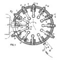
Figure 1 shows a schematic side view of the die-ring for tongue-shaped lollipops and a supply means shown 90° turned; -
Figure 2 shows a schematic view of the die-ring according to the bent line II-II offigure 1 ; -
Figures 3 to 6 show cross-sections at a smaller scale according to the lines III-III to VI-VI offigure 1 so as to elucidate various stages of the lollipop-making process; and -
figures 7 and 8 show at the same scale asfigures 1 and2 two alternatives of the machine for making round and oval lollipops, respectively; -
Figure 9 shows the inventive pressing curve; -
Figure 10 shows the outer ring; -
Figure 11 shows the three dimensionally shaped curve. - The machine which is schematically indicated in the drawings is used for shearing pieces of
sugar 1 from asugar bar 2, which pieces of sugar being subsequently pressed to a confectionary lollipop. The machine substantially consists of a supply means which is provide with twoforward rollers ring 6 havingshear blades 7 and pairs ofouter stamps 8 andinner stamps 9. - A
fixed blade 10 is mounted between theforward rollers shear blades 7 applied in the die-ring 6. These shear-blades7 have an appearance adapted to the appearance of thepress rooms 11, in which thepressing stamps lower stamps 9 may pass the shear-blades 7. In the example shown infigures 1 and2 twelve shear-blades 7 having a tongue shaped cavity have been mounted on the die-ring so as to let thelower stamps 9 pass. A stick can be applied in a manner not specified further in order to complete the lollipop. - From
figure 2 it appears that theshearing edge 13 of the shear-blades 7 is at the rear side with respect to the descriptive end 14 of the press room passing the supply means 4, 5 nearest. This is necessary with this embodiment, otherwise the point would become too sharp. However, there also are many other profiles of the press rooms and corresponding pressing stamps, and thus shear-blades 7 possible:Figure 7 is thereby intended for producing so-called "round" lollipops, andfigure 8 for producing "oval" lollipops. - The
forward rollers parts shear 7 has rotated past the horizontal centre line offigure 1 for some degrees, and thereby shearing a piece of the sugar bar in the direction, theforward rolls blade 7 can cut off asugar piece 1 from thesugar bar 2. Cutting off a sugar piece from the sugar bar takes place between the moving shear-blades 7 and the fixedblade 10. - In order to prevent the
cut sugar piece 1 from ejecting aflap 16 is provided. Just like the shear-blade 7 thisflap 16 has a cross-section corresponding with thepress rooms 11. Theflap 16 may rotate about a centre ofrotation 17 and is usually "open", except, of course, during the time thesugar bar 2 is cut off. - The
sugar piece 1 cut off from thesugar bar 2 is picked up by the shear-blade 7 and theflap 16 prevents if from ejecting. Because of the movements of thepressing stamps sugar piece 1 is subsequently pressed to the desiredlollipop model 3. - The
lower stamps 9 are each provided on arod 18 which at its other end is provided with apressure roll 19 which may exercise a central compressive force on therod 18 and therewith thelower stamp 9. Reposition is effected by areturn roll 20 positioned outside the rod. The paths for controlling therolls - The
upper stamps 8 are each mounted on alid 21 which may pivot about a centre ofrotation 22. The fivelower lids 21 are open infigure 1 . As a result a completedlollipop 3 can be submitted to a removing disc 23 which infigure 1 is schematically indicated by a dot and clash circle. In the bent part alid 21 can be seen also. - The
lids 21 are closed at those areas where necessary for the production process by a solid guide path, not shown. - The
lollipop 3 obtains the shape of thepress room 11 which is formed by the side walls of the press room and the head sides of thestamps ring 6 thestick 12 of the lollipop is also fed to the die-ring 6 in axial direction so as to be inserted into the lollipop. - Once the
lollipop 3 is completed, thestamps figure 6 to bring the lollipop outside the press room. - For completeness' sake it is remarked that the candy to be produced by the invented machine may have all possible cross-sections, including a square cross-section.
-
Figure 9 shows thepressing curve 15 and its bearing. The pressing curve comprises of a first part 15', which is attached to an arm, which is pivotable around a centre ofrotation 25, which itself is stationary. This arm 24 is pre-tensioned by aspring 28 towards the die-ring 6. The second part of thepressing curve 15" is attached to a second arm 26, which is preferably L-shaped and which is rotatable around a centre ofrotation 27, which is also stationary. This arm is also pre-tensioned towards the die-ring 6 by aspring 29. The outward movement of the arms 24, 26 is preferably limited. While thedie ring 6 is turning, the pressure rolls 19 roll along thepressure curve 15, so that therods 18 and theinner stamps 9 are displaced. Thepressure curve 15 preferably comprises a pressure reduction zone 32, which is more preferably located between the twoparts 15', 15" of the pressure curve, more preferably extends in the end zone of part 15' and in the entry-zone ofpart 15". In this pressure reduction zone 32, the pressure on the piece to be formed is reduced in order to, for example, insert a stick into the candy bar material in thedie 11. After the stick has been inserted, the pressure is increased again in order to utilize a good connection between the candy bar and the stick and/or to give the cut off piece its final shape. Furthermore, the inventive machine comprises an ejecting curve, which co-acts with thereturn roll 20. This ejecting curve moves the inner stamp further into or beyond thepress chambers 11 of the die-ring in order to remove the candies without a stick and/or excess candy bar material from thepress chambers 11. The inventive machine further comprises anopening curve 30 which also co-acts with the return rolls 20 of the inner stamp and pushes the stamp well away from the pressing chamber, to provide space for the shear means 7, 10. -
Figure 10 shows theouter ring 34, which is stationary. This outer ring comprises a pressing zone, which has a multitude ofrolls 33, which are arrayed along a line, whereas thepressing zone 34 comprises in the present example four lines which are arranged in parallel. The rolls of two adjacent lines are staggered, to assure, that the outer stamp and/or the lid are always in contact with one preferably two rolls. This pressing chamber either holds in place or moveslid 21 towards the inner stamp, after the lid has been closed in theclosing zone 37. The outer stamp is attached to or part oflid 21. Thislid 21 rolls along therolls 33. Due to these rolls, the friction between thelid 21 and the outer ring 35 is tremendously reduced, so that the wear of the lid is also significantly reduced. The lid is preferably made of metal and/or comprises an inlay which is made of a metal. - Furthermore, the outer ring comprises an
opening zone 36, which opens the lid in order to remove the candy from the press chamber and/or in order to clean the press chamber. Thisopening zone 36 is utilized as a three dimensional shaped curved, which is according to the present invention milled from a piece of metal and consequently very stable and very precisely formed. -
Figure 11 shows the opening zone of theouter ring 34. As can be seen, thelid 21 to whichstamp 8 is attached, has already been opened, so that the lollipop can be removed from thechamber 11 and transported away by wheel 23, which hasgrooves 40 for the stick of the lollipop at its circumference. Thelip 21 has its surface opposite of the stamp 8 ametal inlay 39, which comes into contact with therolls 33 in the pressure zone 35 ofring 34. Thelid 21 is opened by the three dimensionally shapedcurve 38 in theopening zone 36. Thiscurve 38 has preferably two opposite surfaces, which are in contact with thelid 21, while it rotates along this zone. The two surfaces fix the lid in a certain position alter the position of thelid 21, which is pivotable around the center of rotation 41. The part comprising the three dimensionally shapedcurve 38 is milled out of a metal part and thus the motion of thelid 21 is very precise and the part comprising thecurve 38 is very stable. -
- 1
- cut pieces
- 2
- bar of material
- 3
- lollipop
- 4
- supply means
- 5
- supply means
- 6
- die ring
- 7
- shear means, shear blades
- 8
- outer pressing stamp
- 9
- inner pressing stamp
- 10
- shear means, shear blade
- 11
- press chambers
- 12
- stick
- 13
- shearing edge
- 14
- descriptive end
- 15
- pressing curve
- 15'
- first part of the pressing curve
- 15"
- second part of the pressing curve
- 16
- flap
- 17
- center of rotation
- 18
- rod
- 19
- pressure roll
- 20
- return roll
- 21
- lid
- 22
- center of rotation
- 23
- removing disk
- 24
- first arm
- 25
- center of rotation
- 26
- second arm
- 27
- center of rotation
- 28
- spring
- 29
- spring
- 30
- opening curve
- 31
- ejecting curve
- 32
- pressure reduction zone
- 33
- rolls
- 34
- outer ring
- 35
- pressure zone
- 36
- opening zone
- 37
- filling and closing zone
- 38
- three dimensional shaped curve
- 39
- inlay
- 40
- grooves to hold the stick
- 41
- center of rotation
Claims (10)
- Machine for producing candy from a mass (2) of sugar bar or similar material, comprising:- a rotatable die-ring (6) having an axis of rotation and a number of circumferentially spaced, radially extending press chambers (11),- supply means (4, 5) for feeding a bar (2) into the press chambers (11)- shear-means (7, 10) at each press chamber (11) for cutting off pieces (1) off the bar of material,- a pair of inner- and outer stamps (9, 8) per press chamber for pressing the piece into the desired shape, whereas at least the inner stamp (9) is displaceable during pressing and the inner stamp (9) is driven by a pressure curve (15),
characterized in, that the pressure curve (15) comprises two parts (15', 15"), which are adjustable individually and that the curve (15) comprises a pressure reduction zone (32), in which a stick is inserted into the cut off piece. - Machine according to claim 1, characterized in, that the each part of the pressure curve (15', 15") is attached to an arm (24, 25), respectively,
- Machine according to claim 2, characterized in that at least one arm, preferably both arms (24, 25) are pivotable around a center of rotation (25, 27), respectively.
- Machine according to one of claims 2 or 3, characterized in, that at least one part of the pressure curve (15', 15") is pre-tensioned towards the die-ring (6).
- Machine according to one of the preceding claims, characterized in, that the pressure curve (15) is self-adjusting.
- Machine according to one of the preceding claims, characterized in, that it comprises a stationary outer ring (34).
- Machine according to claim 6, characterized in, that the outer ring comprises a pressure zone (35), whereas, at least in this pressure zone (35) rolls (33) are located.
- Machine according to one of the preceding claims, characterized in, that the outer stamp (8) is attached to a lid (21).
- Machine according to claim 8, characterized in, that the lid (21) is rolling up along the rolls (33) during the rotation of the die-ring (6).
- Machine according to claims 6 - 9, characterized in, that the outer ring further comprises an opening zone (36), which opens the lid (21), whereas the opening zone is a three-dimensionally shaped curve, which is a milled piece of metal.
Priority Applications (6)
| Application Number | Priority Date | Filing Date | Title |
|---|---|---|---|
| ES09009813.8T ES2507512T3 (en) | 2009-07-29 | 2009-07-29 | Candy Molding Machine |
| EP09009813.8A EP2279668B1 (en) | 2009-07-29 | 2009-07-29 | Candy moulding machine |
| CN201080043462.1A CN102647914B (en) | 2009-07-29 | 2010-07-22 | Sweets shaper |
| MX2012001237A MX2012001237A (en) | 2009-07-29 | 2010-07-22 | Candy moulding machine. |
| BR112012008131-4A BR112012008131B1 (en) | 2009-07-29 | 2010-07-22 | SWEET PRODUCTION MACHINE FROM A SUGAR BAR PASTA |
| PCT/EP2010/004497 WO2011012260A1 (en) | 2009-07-29 | 2010-07-22 | Candy moulding machine |
Applications Claiming Priority (1)
| Application Number | Priority Date | Filing Date | Title |
|---|---|---|---|
| EP09009813.8A EP2279668B1 (en) | 2009-07-29 | 2009-07-29 | Candy moulding machine |
Publications (2)
| Publication Number | Publication Date |
|---|---|
| EP2279668A1 EP2279668A1 (en) | 2011-02-02 |
| EP2279668B1 true EP2279668B1 (en) | 2014-07-16 |
Family
ID=41600300
Family Applications (1)
| Application Number | Title | Priority Date | Filing Date |
|---|---|---|---|
| EP09009813.8A Active EP2279668B1 (en) | 2009-07-29 | 2009-07-29 | Candy moulding machine |
Country Status (6)
| Country | Link |
|---|---|
| EP (1) | EP2279668B1 (en) |
| CN (1) | CN102647914B (en) |
| BR (1) | BR112012008131B1 (en) |
| ES (1) | ES2507512T3 (en) |
| MX (1) | MX2012001237A (en) |
| WO (1) | WO2011012260A1 (en) |
Families Citing this family (3)
| Publication number | Priority date | Publication date | Assignee | Title |
|---|---|---|---|---|
| ES2533040T3 (en) * | 2012-06-20 | 2015-04-07 | Gea Food Solutions Weert B.V. | Candy Molding Machine |
| CN109648637B (en) * | 2019-02-20 | 2024-01-16 | 江苏海特尔机械有限公司 | Walking stick candy rotary shearing synchronous mechanism |
| CN111329092A (en) * | 2020-03-26 | 2020-06-26 | 张克军 | Feed production equipment convenient for cleaning and feeding |
Family Cites Families (7)
| Publication number | Priority date | Publication date | Assignee | Title |
|---|---|---|---|---|
| US1272073A (en) * | 1917-02-08 | 1918-07-09 | Wladyslaw Majewski | Rotary compression-machine. |
| CH229180A (en) * | 1940-04-08 | 1943-10-15 | Sollich Robert | Device for embossing sweets from an endless strand of sugar paste and for wrapping the embossed sweets in wax paper. |
| US3014240A (en) * | 1959-12-31 | 1961-12-26 | Procter & Gamble | Tablet press |
| US4212609A (en) * | 1978-05-17 | 1980-07-15 | Fay Rudolph J | Method and apparatus for producing shaped and sized food articles |
| NL9100383A (en) * | 1991-03-01 | 1992-10-01 | Derckx Henricus A J M | MACHINE FOR MANUFACTURING CANDIES. |
| NL1024700C2 (en) * | 2003-11-04 | 2005-05-09 | C F S Weert B V | Lolly machine. |
| DE102005018077A1 (en) * | 2005-04-19 | 2006-10-26 | Robert Bosch Gmbh | Device for forming goods made of a mass strand |
-
2009
- 2009-07-29 EP EP09009813.8A patent/EP2279668B1/en active Active
- 2009-07-29 ES ES09009813.8T patent/ES2507512T3/en active Active
-
2010
- 2010-07-22 WO PCT/EP2010/004497 patent/WO2011012260A1/en active Application Filing
- 2010-07-22 MX MX2012001237A patent/MX2012001237A/en active IP Right Grant
- 2010-07-22 CN CN201080043462.1A patent/CN102647914B/en active Active
- 2010-07-22 BR BR112012008131-4A patent/BR112012008131B1/en active IP Right Grant
Also Published As
| Publication number | Publication date |
|---|---|
| ES2507512T3 (en) | 2014-10-15 |
| EP2279668A1 (en) | 2011-02-02 |
| BR112012008131A2 (en) | 2015-09-01 |
| CN102647914B (en) | 2017-12-29 |
| WO2011012260A1 (en) | 2011-02-03 |
| BR112012008131B1 (en) | 2018-06-19 |
| CN102647914A (en) | 2012-08-22 |
| MX2012001237A (en) | 2012-03-26 |
Similar Documents
| Publication | Publication Date | Title |
|---|---|---|
| CN201928928U (en) | Special-shaped lollipop forming machine | |
| EP2080434B1 (en) | Apparatus for rolling and forming food dough | |
| EP2279668B1 (en) | Candy moulding machine | |
| PL130987B1 (en) | Method of making a plastic form piece and apparatus therefor | |
| CA2498693A1 (en) | An apparatus for forming continuous metal grids, in particular producing grids for batteries | |
| EP2116363B1 (en) | A press type apparatus for forming a raw material into a granulated material | |
| CN2843612Y (en) | The pusher lotus seeds hulling machine of circular arc leading screw | |
| EP3030091B1 (en) | Lollipop molding machine with a die set | |
| CN109848275A (en) | The stretching of metal iron-clad, punching automation process units | |
| CN101456190A (en) | Slicer for edible meat with round cutter | |
| EP2676550B1 (en) | Candy moulding machine | |
| EP0501574B1 (en) | A candy-molding machine | |
| EP2374581B1 (en) | Device for cutting a food product | |
| AU626272B2 (en) | A method of machining an oblong workpiece and a machine for performing the method | |
| CN2935822Y (en) | Particle sorting and shaping machine for milk sweets | |
| JP4040990B2 (en) | Rotary compression molding machine | |
| CN107470545A (en) | The excision forming device of screw forming machine | |
| EP3578050B1 (en) | Disc-shaped mold for shaping dough | |
| EP1000549A2 (en) | Chain mold for making soft-centred sweets | |
| JP3706994B2 (en) | Rolling equipment in multi-stage forging machine | |
| CN2760973Y (en) | Forming mould of sweet and sweet forming machine | |
| CN211020830U (en) | Rolling and forming machine for special-shaped candy sticks | |
| JP4022161B2 (en) | Rotary compression molding machine | |
| TWM399613U (en) | Forming structure of dumpling machine | |
| JP5430343B2 (en) | Punching device and punching method |
Legal Events
| Date | Code | Title | Description |
|---|---|---|---|
| PUAI | Public reference made under article 153(3) epc to a published international application that has entered the european phase |
Free format text: ORIGINAL CODE: 0009012 |
|
| AK | Designated contracting states |
Kind code of ref document: A1 Designated state(s): AT BE BG CH CY CZ DE DK EE ES FI FR GB GR HR HU IE IS IT LI LT LU LV MC MK MT NL NO PL PT RO SE SI SK SM TR |
|
| AX | Request for extension of the european patent |
Extension state: AL BA RS |
|
| 17P | Request for examination filed |
Effective date: 20110705 |
|
| 17Q | First examination report despatched |
Effective date: 20110728 |
|
| GRAP | Despatch of communication of intention to grant a patent |
Free format text: ORIGINAL CODE: EPIDOSNIGR1 |
|
| INTG | Intention to grant announced |
Effective date: 20140228 |
|
| RIN1 | Information on inventor provided before grant (corrected) |
Inventor name: ASMA, FRINUS S.J. |
|
| GRAS | Grant fee paid |
Free format text: ORIGINAL CODE: EPIDOSNIGR3 |
|
| GRAA | (expected) grant |
Free format text: ORIGINAL CODE: 0009210 |
|
| RAP1 | Party data changed (applicant data changed or rights of an application transferred) |
Owner name: GEA FOOD SOLUTIONS WEERT B.V. |
|
| AK | Designated contracting states |
Kind code of ref document: B1 Designated state(s): AT BE BG CH CY CZ DE DK EE ES FI FR GB GR HR HU IE IS IT LI LT LU LV MC MK MT NL NO PL PT RO SE SI SK SM TR |
|
| REG | Reference to a national code |
Ref country code: GB Ref legal event code: FG4D |
|
| REG | Reference to a national code |
Ref country code: CH Ref legal event code: EP |
|
| REG | Reference to a national code |
Ref country code: IE Ref legal event code: FG4D |
|
| REG | Reference to a national code |
Ref country code: AT Ref legal event code: REF Ref document number: 676985 Country of ref document: AT Kind code of ref document: T Effective date: 20140815 |
|
| REG | Reference to a national code |
Ref country code: DE Ref legal event code: R096 Ref document number: 602009025271 Country of ref document: DE Effective date: 20140828 |
|
| REG | Reference to a national code |
Ref country code: ES Ref legal event code: FG2A Ref document number: 2507512 Country of ref document: ES Kind code of ref document: T3 Effective date: 20141015 |
|
| REG | Reference to a national code |
Ref country code: NL Ref legal event code: VDEP Effective date: 20140716 |
|
| REG | Reference to a national code |
Ref country code: AT Ref legal event code: MK05 Ref document number: 676985 Country of ref document: AT Kind code of ref document: T Effective date: 20140716 |
|
| REG | Reference to a national code |
Ref country code: LT Ref legal event code: MG4D |
|
| PG25 | Lapsed in a contracting state [announced via postgrant information from national office to epo] |
Ref country code: BG Free format text: LAPSE BECAUSE OF FAILURE TO SUBMIT A TRANSLATION OF THE DESCRIPTION OR TO PAY THE FEE WITHIN THE PRESCRIBED TIME-LIMIT Effective date: 20141016 Ref country code: NO Free format text: LAPSE BECAUSE OF FAILURE TO SUBMIT A TRANSLATION OF THE DESCRIPTION OR TO PAY THE FEE WITHIN THE PRESCRIBED TIME-LIMIT Effective date: 20141016 Ref country code: SE Free format text: LAPSE BECAUSE OF FAILURE TO SUBMIT A TRANSLATION OF THE DESCRIPTION OR TO PAY THE FEE WITHIN THE PRESCRIBED TIME-LIMIT Effective date: 20140716 Ref country code: GR Free format text: LAPSE BECAUSE OF FAILURE TO SUBMIT A TRANSLATION OF THE DESCRIPTION OR TO PAY THE FEE WITHIN THE PRESCRIBED TIME-LIMIT Effective date: 20141017 Ref country code: LT Free format text: LAPSE BECAUSE OF FAILURE TO SUBMIT A TRANSLATION OF THE DESCRIPTION OR TO PAY THE FEE WITHIN THE PRESCRIBED TIME-LIMIT Effective date: 20140716 Ref country code: FI Free format text: LAPSE BECAUSE OF FAILURE TO SUBMIT A TRANSLATION OF THE DESCRIPTION OR TO PAY THE FEE WITHIN THE PRESCRIBED TIME-LIMIT Effective date: 20140716 Ref country code: PT Free format text: LAPSE BECAUSE OF FAILURE TO SUBMIT A TRANSLATION OF THE DESCRIPTION OR TO PAY THE FEE WITHIN THE PRESCRIBED TIME-LIMIT Effective date: 20141117 |
|
| PG25 | Lapsed in a contracting state [announced via postgrant information from national office to epo] |
Ref country code: AT Free format text: LAPSE BECAUSE OF FAILURE TO SUBMIT A TRANSLATION OF THE DESCRIPTION OR TO PAY THE FEE WITHIN THE PRESCRIBED TIME-LIMIT Effective date: 20140716 Ref country code: PL Free format text: LAPSE BECAUSE OF FAILURE TO SUBMIT A TRANSLATION OF THE DESCRIPTION OR TO PAY THE FEE WITHIN THE PRESCRIBED TIME-LIMIT Effective date: 20140716 Ref country code: LV Free format text: LAPSE BECAUSE OF FAILURE TO SUBMIT A TRANSLATION OF THE DESCRIPTION OR TO PAY THE FEE WITHIN THE PRESCRIBED TIME-LIMIT Effective date: 20140716 Ref country code: IS Free format text: LAPSE BECAUSE OF FAILURE TO SUBMIT A TRANSLATION OF THE DESCRIPTION OR TO PAY THE FEE WITHIN THE PRESCRIBED TIME-LIMIT Effective date: 20141116 Ref country code: CY Free format text: LAPSE BECAUSE OF FAILURE TO SUBMIT A TRANSLATION OF THE DESCRIPTION OR TO PAY THE FEE WITHIN THE PRESCRIBED TIME-LIMIT Effective date: 20140716 Ref country code: NL Free format text: LAPSE BECAUSE OF FAILURE TO SUBMIT A TRANSLATION OF THE DESCRIPTION OR TO PAY THE FEE WITHIN THE PRESCRIBED TIME-LIMIT Effective date: 20140716 |
|
| REG | Reference to a national code |
Ref country code: CH Ref legal event code: PL |
|
| REG | Reference to a national code |
Ref country code: DE Ref legal event code: R097 Ref document number: 602009025271 Country of ref document: DE |
|
| REG | Reference to a national code |
Ref country code: IE Ref legal event code: MM4A |
|
| PG25 | Lapsed in a contracting state [announced via postgrant information from national office to epo] |
Ref country code: DK Free format text: LAPSE BECAUSE OF FAILURE TO SUBMIT A TRANSLATION OF THE DESCRIPTION OR TO PAY THE FEE WITHIN THE PRESCRIBED TIME-LIMIT Effective date: 20140716 Ref country code: LI Free format text: LAPSE BECAUSE OF NON-PAYMENT OF DUE FEES Effective date: 20140731 Ref country code: CH Free format text: LAPSE BECAUSE OF NON-PAYMENT OF DUE FEES Effective date: 20140731 Ref country code: MC Free format text: LAPSE BECAUSE OF FAILURE TO SUBMIT A TRANSLATION OF THE DESCRIPTION OR TO PAY THE FEE WITHIN THE PRESCRIBED TIME-LIMIT Effective date: 20140716 Ref country code: SK Free format text: LAPSE BECAUSE OF FAILURE TO SUBMIT A TRANSLATION OF THE DESCRIPTION OR TO PAY THE FEE WITHIN THE PRESCRIBED TIME-LIMIT Effective date: 20140716 Ref country code: RO Free format text: LAPSE BECAUSE OF FAILURE TO SUBMIT A TRANSLATION OF THE DESCRIPTION OR TO PAY THE FEE WITHIN THE PRESCRIBED TIME-LIMIT Effective date: 20140716 Ref country code: CZ Free format text: LAPSE BECAUSE OF FAILURE TO SUBMIT A TRANSLATION OF THE DESCRIPTION OR TO PAY THE FEE WITHIN THE PRESCRIBED TIME-LIMIT Effective date: 20140716 Ref country code: EE Free format text: LAPSE BECAUSE OF FAILURE TO SUBMIT A TRANSLATION OF THE DESCRIPTION OR TO PAY THE FEE WITHIN THE PRESCRIBED TIME-LIMIT Effective date: 20140716 |
|
| PLBE | No opposition filed within time limit |
Free format text: ORIGINAL CODE: 0009261 |
|
| STAA | Information on the status of an ep patent application or granted ep patent |
Free format text: STATUS: NO OPPOSITION FILED WITHIN TIME LIMIT |
|
| REG | Reference to a national code |
Ref country code: FR Ref legal event code: ST Effective date: 20150511 |
|
| 26N | No opposition filed |
Effective date: 20150417 |
|
| GBPC | Gb: european patent ceased through non-payment of renewal fee |
Effective date: 20141016 |
|
| PG25 | Lapsed in a contracting state [announced via postgrant information from national office to epo] |
Ref country code: GB Free format text: LAPSE BECAUSE OF NON-PAYMENT OF DUE FEES Effective date: 20141016 |
|
| PG25 | Lapsed in a contracting state [announced via postgrant information from national office to epo] |
Ref country code: IE Free format text: LAPSE BECAUSE OF NON-PAYMENT OF DUE FEES Effective date: 20140729 Ref country code: FR Free format text: LAPSE BECAUSE OF NON-PAYMENT OF DUE FEES Effective date: 20140916 |
|
| PG25 | Lapsed in a contracting state [announced via postgrant information from national office to epo] |
Ref country code: SI Free format text: LAPSE BECAUSE OF FAILURE TO SUBMIT A TRANSLATION OF THE DESCRIPTION OR TO PAY THE FEE WITHIN THE PRESCRIBED TIME-LIMIT Effective date: 20140716 |
|
| PG25 | Lapsed in a contracting state [announced via postgrant information from national office to epo] |
Ref country code: SM Free format text: LAPSE BECAUSE OF FAILURE TO SUBMIT A TRANSLATION OF THE DESCRIPTION OR TO PAY THE FEE WITHIN THE PRESCRIBED TIME-LIMIT Effective date: 20140716 |
|
| PG25 | Lapsed in a contracting state [announced via postgrant information from national office to epo] |
Ref country code: MT Free format text: LAPSE BECAUSE OF FAILURE TO SUBMIT A TRANSLATION OF THE DESCRIPTION OR TO PAY THE FEE WITHIN THE PRESCRIBED TIME-LIMIT Effective date: 20140716 |
|
| PG25 | Lapsed in a contracting state [announced via postgrant information from national office to epo] |
Ref country code: LU Free format text: LAPSE BECAUSE OF NON-PAYMENT OF DUE FEES Effective date: 20140729 Ref country code: HU Free format text: LAPSE BECAUSE OF FAILURE TO SUBMIT A TRANSLATION OF THE DESCRIPTION OR TO PAY THE FEE WITHIN THE PRESCRIBED TIME-LIMIT; INVALID AB INITIO Effective date: 20090729 Ref country code: BE Free format text: LAPSE BECAUSE OF FAILURE TO SUBMIT A TRANSLATION OF THE DESCRIPTION OR TO PAY THE FEE WITHIN THE PRESCRIBED TIME-LIMIT Effective date: 20140716 Ref country code: HR Free format text: LAPSE BECAUSE OF FAILURE TO SUBMIT A TRANSLATION OF THE DESCRIPTION OR TO PAY THE FEE WITHIN THE PRESCRIBED TIME-LIMIT Effective date: 20140716 |
|
| PG25 | Lapsed in a contracting state [announced via postgrant information from national office to epo] |
Ref country code: MK Free format text: LAPSE BECAUSE OF FAILURE TO SUBMIT A TRANSLATION OF THE DESCRIPTION OR TO PAY THE FEE WITHIN THE PRESCRIBED TIME-LIMIT Effective date: 20140716 |
|
| PGFP | Annual fee paid to national office [announced via postgrant information from national office to epo] |
Ref country code: TR Payment date: 20190724 Year of fee payment: 11 |
|
| P01 | Opt-out of the competence of the unified patent court (upc) registered |
Effective date: 20230523 |
|
| PGFP | Annual fee paid to national office [announced via postgrant information from national office to epo] |
Ref country code: IT Payment date: 20230727 Year of fee payment: 15 Ref country code: ES Payment date: 20230821 Year of fee payment: 15 |
|
| PGFP | Annual fee paid to national office [announced via postgrant information from national office to epo] |
Ref country code: DE Payment date: 20230720 Year of fee payment: 15 |