EP0501574B1 - A candy-molding machine - Google Patents
A candy-molding machine Download PDFInfo
- Publication number
- EP0501574B1 EP0501574B1 EP92200501A EP92200501A EP0501574B1 EP 0501574 B1 EP0501574 B1 EP 0501574B1 EP 92200501 A EP92200501 A EP 92200501A EP 92200501 A EP92200501 A EP 92200501A EP 0501574 B1 EP0501574 B1 EP 0501574B1
- Authority
- EP
- European Patent Office
- Prior art keywords
- die
- ring
- bar
- stamps
- press
- Prior art date
- Legal status (The legal status is an assumption and is not a legal conclusion. Google has not performed a legal analysis and makes no representation as to the accuracy of the status listed.)
- Expired - Lifetime
Links
Images

Classifications
-
- B—PERFORMING OPERATIONS; TRANSPORTING
- B30—PRESSES
- B30B—PRESSES IN GENERAL
- B30B11/00—Presses specially adapted for forming shaped articles from material in particulate or plastic state, e.g. briquetting presses, tabletting presses
- B30B11/02—Presses specially adapted for forming shaped articles from material in particulate or plastic state, e.g. briquetting presses, tabletting presses using a ram exerting pressure on the material in a moulding space
- B30B11/12—Presses specially adapted for forming shaped articles from material in particulate or plastic state, e.g. briquetting presses, tabletting presses using a ram exerting pressure on the material in a moulding space co-operating with moulds on the circumference of a rotating drum
-
- A—HUMAN NECESSITIES
- A23—FOODS OR FOODSTUFFS; TREATMENT THEREOF, NOT COVERED BY OTHER CLASSES
- A23G—COCOA; COCOA PRODUCTS, e.g. CHOCOLATE; SUBSTITUTES FOR COCOA OR COCOA PRODUCTS; CONFECTIONERY; CHEWING GUM; ICE-CREAM; PREPARATION THEREOF
- A23G3/00—Sweetmeats; Confectionery; Marzipan; Coated or filled products
- A23G3/02—Apparatus specially adapted for manufacture or treatment of sweetmeats or confectionery; Accessories therefor
- A23G3/0236—Shaping of liquid, paste, powder; Manufacture of moulded articles, e.g. modelling, moulding, calendering
- A23G3/0252—Apparatus in which the material is shaped at least partially in a mould, in the hollows of a surface, a drum, an endless band, or by a drop-by-drop casting or dispensing of the material on a surface, e.g. injection moulding, transfer moulding
- A23G3/0289—Compression moulding of paste, e.g. in the form of a ball or rope or other preforms, or of a powder or granules
-
- A—HUMAN NECESSITIES
- A23—FOODS OR FOODSTUFFS; TREATMENT THEREOF, NOT COVERED BY OTHER CLASSES
- A23G—COCOA; COCOA PRODUCTS, e.g. CHOCOLATE; SUBSTITUTES FOR COCOA OR COCOA PRODUCTS; CONFECTIONERY; CHEWING GUM; ICE-CREAM; PREPARATION THEREOF
- A23G3/00—Sweetmeats; Confectionery; Marzipan; Coated or filled products
- A23G3/02—Apparatus specially adapted for manufacture or treatment of sweetmeats or confectionery; Accessories therefor
- A23G3/12—Apparatus for moulding candy in the plastic state
-
- B—PERFORMING OPERATIONS; TRANSPORTING
- B30—PRESSES
- B30B—PRESSES IN GENERAL
- B30B11/00—Presses specially adapted for forming shaped articles from material in particulate or plastic state, e.g. briquetting presses, tabletting presses
- B30B11/02—Presses specially adapted for forming shaped articles from material in particulate or plastic state, e.g. briquetting presses, tabletting presses using a ram exerting pressure on the material in a moulding space
- B30B11/025—Presses specially adapted for forming shaped articles from material in particulate or plastic state, e.g. briquetting presses, tabletting presses using a ram exerting pressure on the material in a moulding space whereby the material is transferred into the press chamber by relative movement between a ram and the press chamber
Definitions
- the invention relates to a machine for producing candy from a mass of sugar bar or similar material as defined in the preamble of claim 1.
- a machine for producing candy from a mass of sugar bar comprises a stepwise rotatable die-ring having axially arranged press rooms.
- the die-ring carries inner press stamps and the outer press stamps are fixed stationary and separate of the die-ring. Flaps for preventing centrifugal ejection of pieces of sugar bar are not disclosed.
- Each inner pressing stamp also called lower stamp, is mounted on the extremity of a rod being at its rear side provided with a central pressing roll and a return roll, said rolls controlling the movements of the stamps connected therewith.
- a means may be applied to provide the cut piece of candy with a stick before it is discharged from the machine.
- the machine which is schematically indicated in the drawing is used for shearing pieces of sugar 1 from a sugar bar 2, which pieces of sugar being subsequently pressed to a confectionery lollipop 3.
- the machine substantially consists of a supply means which is provided with two forward rollers 4 and 5, a die-ring 6 having shear-blades 7 and pairs of outer stamps 8 and inner stamps 9.
- a fixed blade 10 is mounted between the forward rollers 4 and 5 and the largest path which is described by the shear-blades 7 applied in the die-ring 6.
- These shear-blades 7 have an appearance adapted to the appearance of the press rooms 11, in which the pressing stamps 8 and 9 can move in such a manner that the lower stamps 9 may pass the shear-blades 7.
- twelve shear-blades 7 having a tongue-shaped cavity have been mounted on the die-ring 6 so as to let the lower stamps 9 pass.
- a stick 12 can be applied in a manner not specified further in order to complete the lollipop.
- the forward rollers 4 and 5 turn intermittingly round in the rotation direction of the arrows.
- the parts 7 and 10 are shown as the shear blades of the sugar-strand-shearing-device.
- shear-blade 7 has rotated past the horizontal centre line of figure 1 for some degrees, and thereby shearing a piece 1 of the sugar bar 2
- the forward rolls 4 and 5 move the sugar bar 2 in the direction reciprocal the direction of rotation of said rolls. This forward movement is stopped before the next shear-blade 7 can cut off a sugar piece 1 from the sugar bar 2. Cutting off a sugar piece from the sugar bar takes place between the moving shear-blades 7 and the fixed blade 10.
- a flap 16 is provided. Just like the shear-blade 7 this flap 16 has a cross-section corresponding with the press rooms 11.
- the flap 16 may rotate about a centre of rotation 17 and is usually "open", except, of course, during the time the sugar bar 2 is cut off.
- the sugar piece 1 cut off from the sugar bar 2 is picked up by the shear-blade 7 and the flap 16 prevents it from ejecting. Because of the movements of the pressing stamps 8, 9 the sugar piece 1 is subsequently pressed to the desired lollipop model 3.
- the lower stamps 9 are each provided on a rod 18 which at its other end is provided with a pressure roll 19 which may exercise a central compressive force on the rod 18 and therewith the lower stamp 9. Reposition is effected by a return roll 20 positioned outside the rod.
- the paths for controlling the rolls 19 and 20 have for clarity's sake been omitted in the drawing.
- the upper stamps 8 are each mounted on a lid 21 which may pivot about a centre of rotation 22.
- the five lower lids 21 are open in figure 1.
- a completed lollipop 3 can be submitted to a removing disc 23 which in figure 1 is schematically indicated by a dot and dash circle.
- a lid 21 can be seen also.
- the lids 21 are closed at those areas where necessary for the production process by a solid guide path, not shown.
- the lollipop 3 obtains the shape of the press room 11 which is formed by the side walls of the press room and the head sides of the stamps 8 and 9. During the rotary movement of the die-ring 6 the stick 12 of the lollipop is also fed to the die-ring 6 in axial direction so as to be inserted into the lollipop.
- the stamps 8 and 9 move into the position of figure 6 to bring the lollipop outside the press room.
- the candy to be produced by the invented machine may have all possible cross-sections, including a square cross-section.
Landscapes
- Engineering & Computer Science (AREA)
- Mechanical Engineering (AREA)
- Life Sciences & Earth Sciences (AREA)
- Chemical & Material Sciences (AREA)
- Food Science & Technology (AREA)
- Polymers & Plastics (AREA)
- Confectionery (AREA)
Description
- The invention relates to a machine for producing candy from a mass of sugar bar or similar material as defined in the preamble of claim 1.
- Such an apparatus is known from US patent specification 1,785,904. In this known machine the bar of material is radially fed to a shearing device consisting of a stationary plate having a radial inlet for the material, and a blade which transfers the cut material to an axial die-cavity of a die-disc in which the material is processed further. In a shearing device operating in this manner the material may, depending on the speed of rotation of the die-disc, either be ejected due to the centrifugal force or may on the contrary be stuck to the blade, so that the machine has to be stopped to correct the undesired situation.
- It is an object of the present invention to provide a machine for producing candy from a mass of sugar bar or similar material in which the ejection of pieces of sugar bar is substantially reduced.
- This object is obtained by the present invention in accordance with the characterizing part of claim 1. Due to the radially placed pressing stamps, the axial feeding of the bar of material and the flaps, material is prevented from ejecting from the die-ring.
- In US-A-4,168,139 a machine for producing candy from a mass of sugar bar is disclosed in which the machine comprises a stepwise rotatable die-ring having axially arranged press rooms. The die-ring carries inner press stamps and the outer press stamps are fixed stationary and separate of the die-ring. Flaps for preventing centrifugal ejection of pieces of sugar bar are not disclosed.
- Each inner pressing stamp, also called lower stamp, is mounted on the extremity of a rod being at its rear side provided with a central pressing roll and a return roll, said rolls controlling the movements of the stamps connected therewith.
- A means may be applied to provide the cut piece of candy with a stick before it is discharged from the machine.
- The invention will be further illustrated hereinafter on the basis of the drawing indicating, by way of example, a machine for making lollipops. In the drawing:
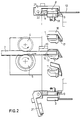
- figure 1 shows a schematic side view of the die-ring for tongue-shaped lollipops and a supply means shown 90o turned;
- figure 2 shows a schematic view of the die-ring according to the bent line II-II of figure 1;
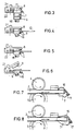
- figures 3 to 6 show cross-sections at a smaller scale according to the lines III-III to VI-VI of figure 1 so as to elucidate various stages of the lollipop-making process; and
- figures 7 and 8 show at the same scale as figures 1 and 2 two alternatives of the machine for making round and oval lollipops, respectively.
- The machine which is schematically indicated in the drawing is used for shearing pieces of sugar 1 from a
sugar bar 2, which pieces of sugar being subsequently pressed to aconfectionery lollipop 3. The machine substantially consists of a supply means which is provided with twoforward rollers ring 6 having shear-blades 7 and pairs ofouter stamps 8 andinner stamps 9. - A
fixed blade 10 is mounted between theforward rollers blades 7 applied in the die-ring 6. These shear-blades 7 have an appearance adapted to the appearance of thepress rooms 11, in which thepressing stamps lower stamps 9 may pass the shear-blades 7. In the example shown in figures 1 and 2 twelve shear-blades 7 having a tongue-shaped cavity have been mounted on the die-ring 6 so as to let thelower stamps 9 pass. Astick 12 can be applied in a manner not specified further in order to complete the lollipop. - From figure 2 it appears that the
shearing edge 13 of the shear-blades 7 is at the rear side with respect to the descriptive end 14 of the press room passing the supply means 4, 5 nearest. This is necessary with this embodiment, otherwise the point would become too sharp. However, there also are many other profiles of the press rooms and corresponding pressing stamps, and thus shear-blades 7 possible: figure 7 is thereby intended for producing so-called "round" lollipops, and figure 8 for producing "oval" lollipops. - The
forward rollers parts blade 7 has rotated past the horizontal centre line of figure 1 for some degrees, and thereby shearing a piece 1 of thesugar bar 2, theforward rolls sugar bar 2 in the direction reciprocal the direction of rotation of said rolls. This forward movement is stopped before the next shear-blade 7 can cut off a sugar piece 1 from thesugar bar 2. Cutting off a sugar piece from the sugar bar takes place between the moving shear-blades 7 and thefixed blade 10. - In order to prevent the cut sugar piece 1 from ejecting a
flap 16 is provided. Just like the shear-blade 7 thisflap 16 has a cross-section corresponding with thepress rooms 11. Theflap 16 may rotate about a centre ofrotation 17 and is usually "open", except, of course, during the time thesugar bar 2 is cut off. - The sugar piece 1 cut off from the
sugar bar 2 is picked up by the shear-blade 7 and theflap 16 prevents it from ejecting. Because of the movements of thepressing stamps lollipop model 3. - The
lower stamps 9 are each provided on arod 18 which at its other end is provided with apressure roll 19 which may exercise a central compressive force on therod 18 and therewith thelower stamp 9. Reposition is effected by areturn roll 20 positioned outside the rod. The paths for controlling therolls - The
upper stamps 8 are each mounted on alid 21 which may pivot about a centre ofrotation 22. The fivelower lids 21 are open in figure 1. As a result a completedlollipop 3 can be submitted to a removingdisc 23 which in figure 1 is schematically indicated by a dot and dash circle. In the bent part alid 21 can be seen also. - The
lids 21 are closed at those areas where necessary for the production process by a solid guide path, not shown. - The
lollipop 3 obtains the shape of thepress room 11 which is formed by the side walls of the press room and the head sides of thestamps ring 6 thestick 12 of the lollipop is also fed to the die-ring 6 in axial direction so as to be inserted into the lollipop. - Once the
lollipop 3 is completed, thestamps - For completeness' sake it is remarked that the candy to be produced by the invented machine may have all possible cross-sections, including a square cross-section.
Claims (3)
- A machine for producing candy from a mass of sugar bar or similar material, said machine comprising:
a rotatable die-ring (6) having an axis of rotation and a number of circumferentially spaced, radially extending press rooms (11),
supply means (4, 5) for intermittently feeding a bar of material into the press rooms (11),
a fixed shear blade (10) positioned stationary between the supply means (4, 5) and the die-ring (6),
a same number of shear blades (7) as the number of press rooms (11), each shear blade (7) being attached to the die-ring (6) for cutting off pieces (1) of the bar of material in cooperation with the fixed shear blade (10), and
a same number of outer and inner pressing stamps (8, 9) as the number of press rooms (11), said outer and inner pressing stamps (8, 9) being carried by the die-ring (6) and being displaceable for pressing the pieces (1) of the bar of material (2),
characterized in that each shear blade (7) has a radial shearing edge (13),
in that the supply means (4, 5) are arranged for feeding the bar of material (2) intermittently along a path of travel in a direction parallel to the axis of rotation of the die-ring (6),
in that each outer pressing stamp (8) is mounted on a tangential centre of rotation (22),
in that each inner pressing stamp (9) is arranged for radial displacement for pressing the cut pieces (1) against its corresponding outer pressing stamp (8),
in that a same number of flaps (16) as the number of shear blades (7) is carried by the die-ring (6), each flap (16) being provided opposite its corresponding shear blade (7) and being rotatably mounted on a radial centre of rotation (17), each press room (11) being formed by the side walls of the press room and the head sides of the stamps (8) and (9) - A machine according to claim 1, characterized in that each inner pressing stamp (9) is mounted on the extremity of a rod (18) being at its rear side provided with a central press roll (1) and a return roll (20), said rolls (19, 20) controlling the movements of the stamps (9) connected therewith.
- A machine according to claim 1 or 2, characterized in that a means is applied to provide the cut piece (1) with a stick (12) before it is discharged from the machine.
Applications Claiming Priority (2)
| Application Number | Priority Date | Filing Date | Title |
|---|---|---|---|
| NL9100383A NL9100383A (en) | 1991-03-01 | 1991-03-01 | MACHINE FOR MANUFACTURING CANDIES. |
| NL9100383 | 1991-03-01 |
Publications (2)
| Publication Number | Publication Date |
|---|---|
| EP0501574A1 EP0501574A1 (en) | 1992-09-02 |
| EP0501574B1 true EP0501574B1 (en) | 1995-04-19 |
Family
ID=19858966
Family Applications (1)
| Application Number | Title | Priority Date | Filing Date |
|---|---|---|---|
| EP92200501A Expired - Lifetime EP0501574B1 (en) | 1991-03-01 | 1992-02-21 | A candy-molding machine |
Country Status (5)
| Country | Link |
|---|---|
| US (1) | US5240401A (en) |
| EP (1) | EP0501574B1 (en) |
| DE (1) | DE69202081T2 (en) |
| MX (1) | MX9200760A (en) |
| NL (1) | NL9100383A (en) |
Cited By (2)
| Publication number | Priority date | Publication date | Assignee | Title |
|---|---|---|---|---|
| EP2279668A1 (en) | 2009-07-29 | 2011-02-02 | CFS Weert B.V. | Candy moulding machine |
| EP2676550A1 (en) | 2012-06-20 | 2013-12-25 | GEA CFS Weert B.V. | Candy moulding machine |
Families Citing this family (1)
| Publication number | Priority date | Publication date | Assignee | Title |
|---|---|---|---|---|
| DE29520473U1 (en) * | 1995-12-22 | 1996-03-28 | Koch, Rudolf, 83646 Bad Tölz | Device for making tablets |
Family Cites Families (14)
| Publication number | Priority date | Publication date | Assignee | Title |
|---|---|---|---|---|
| US1689879A (en) * | 1928-10-30 | Machine relating to the production of candy | ||
| GB191310597A (en) * | 1912-08-23 | 1913-08-21 | British Ever Ready Electrical | Improvements in or relating to Handles for Hand Lamps & other Articles. |
| US1272073A (en) * | 1917-02-08 | 1918-07-09 | Wladyslaw Majewski | Rotary compression-machine. |
| US1785904A (en) * | 1927-04-29 | 1930-12-23 | Robert W Hompe | Candy molding |
| US1958380A (en) * | 1932-07-30 | 1934-05-08 | V O Hermann Corp | Machine for making lollipops |
| US3014240A (en) * | 1959-12-31 | 1961-12-26 | Procter & Gamble | Tablet press |
| US3285199A (en) * | 1962-09-22 | 1966-11-15 | Rose Brothers Ltd | Production of lollipops or like sweets |
| NL6702160A (en) * | 1967-02-13 | 1968-08-14 | ||
| BE790198A (en) * | 1971-10-27 | 1973-02-15 | Aquarius C | DEVICE FOR MANUFACTURING LOLLIES |
| NL150315B (en) * | 1972-04-18 | 1976-08-16 | Conrardus Hubertus Aquarius | DEVICE FOR MANUFACTURING LOLLY'S. |
| DE2643855C2 (en) * | 1976-09-29 | 1983-03-31 | Robert Bosch Gmbh, 7000 Stuttgart | Device for embossing sweets |
| NL7613131A (en) * | 1976-11-25 | 1978-05-29 | Henrikus Antonius Jacobus Mari | METHOD AND EQUIPMENT FOR THE MANUFACTURE OF CANDY LOLLIES. |
| NL7904629A (en) * | 1979-06-13 | 1980-12-16 | Derckx Henricus A J M | High speed moulding turret for lollipops from syrup - has vertical punches shearing stock pressing and fitting sticks |
| US4556379A (en) * | 1983-05-20 | 1985-12-03 | Toshimasa Ikishima | Sushi shaping apparatus |
-
1991
- 1991-03-01 NL NL9100383A patent/NL9100383A/en not_active Application Discontinuation
-
1992
- 1992-02-14 US US07/837,066 patent/US5240401A/en not_active Expired - Lifetime
- 1992-02-21 DE DE69202081T patent/DE69202081T2/en not_active Expired - Fee Related
- 1992-02-21 EP EP92200501A patent/EP0501574B1/en not_active Expired - Lifetime
- 1992-02-24 MX MX9200760A patent/MX9200760A/en unknown
Cited By (4)
| Publication number | Priority date | Publication date | Assignee | Title |
|---|---|---|---|---|
| EP2279668A1 (en) | 2009-07-29 | 2011-02-02 | CFS Weert B.V. | Candy moulding machine |
| WO2011012260A1 (en) | 2009-07-29 | 2011-02-03 | Cfs Weert B.V. | Candy moulding machine |
| EP2676550A1 (en) | 2012-06-20 | 2013-12-25 | GEA CFS Weert B.V. | Candy moulding machine |
| WO2013189680A2 (en) | 2012-06-20 | 2013-12-27 | Gea Cfs Weert B.V. | Candy moulding machine |
Also Published As
| Publication number | Publication date |
|---|---|
| MX9200760A (en) | 1992-09-01 |
| EP0501574A1 (en) | 1992-09-02 |
| DE69202081D1 (en) | 1995-05-24 |
| DE69202081T2 (en) | 1995-11-30 |
| US5240401A (en) | 1993-08-31 |
| NL9100383A (en) | 1992-10-01 |
Similar Documents
| Publication | Publication Date | Title |
|---|---|---|
| CA1059858A (en) | Machine for paring vegetables or fruits | |
| US6458302B1 (en) | System and method for forming plastic articles | |
| US20130036884A1 (en) | Method and apparatus for punching or perforating moving material webs | |
| PL130987B1 (en) | Method of making a plastic form piece and apparatus therefor | |
| DE4432407A1 (en) | Swirl packaging machine | |
| EP0501574B1 (en) | A candy-molding machine | |
| AU652629B2 (en) | Fruit juice and pulp extractor | |
| DE69910294T2 (en) | Method and device for producing extruded strands of equal length | |
| CA1042403A (en) | Sheet end cutter and stripper | |
| EP3384776B1 (en) | Device for forming pieces of dough to form dough products | |
| EP2279668B1 (en) | Candy moulding machine | |
| EP0273761B1 (en) | An apparatus for supplying a uniform amount of loose food material | |
| DE2739639A1 (en) | METHOD AND DEVICE FOR SUPPLYING A RECEIVING DEVICE WITH A MEASURED QUANTITY OF MATERIAL | |
| DE102010022629A1 (en) | Wrapping machine for tabular foods | |
| DE2603343C3 (en) | Device for cutting cans | |
| EP2374581B1 (en) | Device for cutting a food product | |
| EP0365812A1 (en) | Device for feeding packaging blanks to a folding device | |
| US4224350A (en) | Apparatus and method for selectively ejecting malformed articles | |
| FI63664B (en) | OVER ANCHORING FOR MASKINELL FRAMSTAELLNING AV KUL- ELLER PARISERPOTATIS | |
| AU626272B2 (en) | A method of machining an oblong workpiece and a machine for performing the method | |
| US4430916A (en) | Apparatus for making slats for a slatted blind | |
| US4004502A (en) | Artichoke shaping machine | |
| US186905A (en) | Improvement in machines for making screw-blanks | |
| US2790399A (en) | Machinery for molding and cutting out pieces of plastic material from a web | |
| JP3706994B2 (en) | Rolling equipment in multi-stage forging machine |
Legal Events
| Date | Code | Title | Description |
|---|---|---|---|
| PUAI | Public reference made under article 153(3) epc to a published international application that has entered the european phase |
Free format text: ORIGINAL CODE: 0009012 |
|
| 17P | Request for examination filed |
Effective date: 19920611 |
|
| AK | Designated contracting states |
Kind code of ref document: A1 Designated state(s): DE FR GB |
|
| 17Q | First examination report despatched |
Effective date: 19930223 |
|
| GRAA | (expected) grant |
Free format text: ORIGINAL CODE: 0009210 |
|
| AK | Designated contracting states |
Kind code of ref document: B1 Designated state(s): DE FR GB |
|
| REF | Corresponds to: |
Ref document number: 69202081 Country of ref document: DE Date of ref document: 19950524 |
|
| ET | Fr: translation filed | ||
| PLBE | No opposition filed within time limit |
Free format text: ORIGINAL CODE: 0009261 |
|
| STAA | Information on the status of an ep patent application or granted ep patent |
Free format text: STATUS: NO OPPOSITION FILED WITHIN TIME LIMIT |
|
| 26N | No opposition filed | ||
| REG | Reference to a national code |
Ref country code: GB Ref legal event code: IF02 |
|
| PGFP | Annual fee paid to national office [announced via postgrant information from national office to epo] |
Ref country code: FR Payment date: 20060131 Year of fee payment: 15 |
|
| PGFP | Annual fee paid to national office [announced via postgrant information from national office to epo] |
Ref country code: DE Payment date: 20060330 Year of fee payment: 15 |
|
| REG | Reference to a national code |
Ref country code: FR Ref legal event code: ST Effective date: 20071030 |
|
| PG25 | Lapsed in a contracting state [announced via postgrant information from national office to epo] |
Ref country code: DE Free format text: LAPSE BECAUSE OF NON-PAYMENT OF DUE FEES Effective date: 20070901 |
|
| PG25 | Lapsed in a contracting state [announced via postgrant information from national office to epo] |
Ref country code: FR Free format text: LAPSE BECAUSE OF NON-PAYMENT OF DUE FEES Effective date: 20070228 |
|
| PGFP | Annual fee paid to national office [announced via postgrant information from national office to epo] |
Ref country code: GB Payment date: 20110221 Year of fee payment: 20 |
|
| REG | Reference to a national code |
Ref country code: GB Ref legal event code: PE20 Expiry date: 20120220 |
|
| PG25 | Lapsed in a contracting state [announced via postgrant information from national office to epo] |
Ref country code: GB Free format text: LAPSE BECAUSE OF EXPIRATION OF PROTECTION Effective date: 20120220 |