EP1874505B1 - Cloueuse electrique dont le magasin est pourvu d'un mecanisme de blocage de la lame d'enfoncement - Google Patents
Cloueuse electrique dont le magasin est pourvu d'un mecanisme de blocage de la lame d'enfoncement Download PDFInfo
- Publication number
- EP1874505B1 EP1874505B1 EP06738681A EP06738681A EP1874505B1 EP 1874505 B1 EP1874505 B1 EP 1874505B1 EP 06738681 A EP06738681 A EP 06738681A EP 06738681 A EP06738681 A EP 06738681A EP 1874505 B1 EP1874505 B1 EP 1874505B1
- Authority
- EP
- European Patent Office
- Prior art keywords
- driver blade
- fastener
- magazine
- follower
- nosepiece
- Prior art date
- Legal status (The legal status is an assumption and is not a legal conclusion. Google has not performed a legal analysis and makes no representation as to the accuracy of the status listed.)
- Expired - Fee Related
Links
Images

Classifications
-
- B—PERFORMING OPERATIONS; TRANSPORTING
- B25—HAND TOOLS; PORTABLE POWER-DRIVEN TOOLS; MANIPULATORS
- B25C—HAND-HELD NAILING OR STAPLING TOOLS; MANUALLY OPERATED PORTABLE STAPLING TOOLS
- B25C5/00—Manually operated portable stapling tools; Hand-held power-operated stapling tools; Staple feeding devices therefor
- B25C5/16—Staple-feeding devices, e.g. with feeding means, supports for staples or accessories concerning feeding devices
- B25C5/1665—Staple-feeding devices, e.g. with feeding means, supports for staples or accessories concerning feeding devices with means for preventing jamming or aiding unjamming within the drive channel
-
- B—PERFORMING OPERATIONS; TRANSPORTING
- B25—HAND TOOLS; PORTABLE POWER-DRIVEN TOOLS; MANIPULATORS
- B25C—HAND-HELD NAILING OR STAPLING TOOLS; MANUALLY OPERATED PORTABLE STAPLING TOOLS
- B25C1/00—Hand-held nailing tools; Nail feeding devices
-
- B—PERFORMING OPERATIONS; TRANSPORTING
- B25—HAND TOOLS; PORTABLE POWER-DRIVEN TOOLS; MANIPULATORS
- B25C—HAND-HELD NAILING OR STAPLING TOOLS; MANUALLY OPERATED PORTABLE STAPLING TOOLS
- B25C1/00—Hand-held nailing tools; Nail feeding devices
- B25C1/001—Nail feeding devices
- B25C1/005—Nail feeding devices for rows of contiguous nails
-
- B—PERFORMING OPERATIONS; TRANSPORTING
- B25—HAND TOOLS; PORTABLE POWER-DRIVEN TOOLS; MANIPULATORS
- B25C—HAND-HELD NAILING OR STAPLING TOOLS; MANUALLY OPERATED PORTABLE STAPLING TOOLS
- B25C1/00—Hand-held nailing tools; Nail feeding devices
- B25C1/06—Hand-held nailing tools; Nail feeding devices operated by electric power
-
- B—PERFORMING OPERATIONS; TRANSPORTING
- B25—HAND TOOLS; PORTABLE POWER-DRIVEN TOOLS; MANIPULATORS
- B25C—HAND-HELD NAILING OR STAPLING TOOLS; MANUALLY OPERATED PORTABLE STAPLING TOOLS
- B25C1/00—Hand-held nailing tools; Nail feeding devices
- B25C1/08—Hand-held nailing tools; Nail feeding devices operated by combustion pressure
Definitions
- the present invention relates to fastener-driving tools, also known as power nailers, which are typically powered by combustion, pneumatics, electricity, are powder-activated or otherwise powered.
- fastener-driving tools also known as power nailers, which are typically powered by combustion, pneumatics, electricity, are powder-activated or otherwise powered.
- a plurality of fasteners are sequentially arranged in a magazine and are urged by a biased follower toward a driving end of the magazine where the fasteners are each pushed into a nosepiece. Once in the nosepiece, the fasteners are driven into a workpiece by a reciprocating driver blade.
- a design criterion of most such tools is that the tool should be disabled when the magazine is empty of fasteners. So-called “dry firing” or “blank firing” generates significant stresses in the tool and can damage the workpiece or the tool itself. Indicator mechanisms are known in such tools to indicate to the user when the magazine is empty or almost empty, so that the magazine can be refilled prior to a dry firing condition. In some of these known mechanisms, once a magazine follower reaches a preset point where a relatively few fasteners remain in the magazine, the tool is disabled by locking a workpiece contact element to prevent dry firing.
- a related design problem is that visual indicator systems for preventing dry firing require attention by the operator for effectiveness. If the user is understandably preoccupied with driving fasteners, the status of the magazine may be overlooked, resulting in a dry firing situation due to an empty magazine. In some cases, audible warning systems may also be overlooked when the user is concentrating on fastener application.
- a related design issue is that in some cases, leftover fastener strip segments are prone to "tumble" or become misaligned within the magazine. Such segments can cause the tool to jam, especially in applications where the nail follower or pusher in the magazine fails to strongly urge the fasteners toward the nosepiece. This problem is especially severe when plastic collated fasteners are used. Since the plastic collation media is relatively brittle, the tendency is for the fasteners to become detached from the media and tumble around inside the magazine.
- the magazine follower for a fastener-driving tool, wherein the follower is configured to block downward movement of the driver blade after the driving of the last fastener in a strip or in the magazine.
- a mechanism for preventing jamming includes a follower slidably disposed inside the magazine for urging fasteners toward the nosepiece, and having a formation for engaging the driver blade and preventing driver blade reciprocation after the last fastener in the magazine has been driven.
- a fastener-driving tool in another embodiment, includes a magazine having a first end for receiving fasteners, a second end for delivering fasteners for driving, and a guide channel.
- a nosepiece defines a fastener passage slot in communication with the magazine for receiving fasteners from the second end, and a driver blade path in communication with the slot.
- a driver blade slidably reciprocates in said driver blade path for driving fasteners.
- a follower is slidably disposed inside the magazine and has a first portion for urging fasteners toward the nosepiece and a second portion for engaging the driver blade and preventing driver blade reciprocation after the last fastener in a fastener strip has been driven.
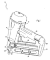
- a fastener-driving tool suitable for use with the present lockout mechanism is generally designated 10. While the tool 10 is depicted as a pneumatic tool, it is contemplated that the present mechanism may also be utilized with combustion-powered, powder, electric-powered, or any other power sources for fastener tools, provided they employ a magazine for sequentially feeding fasteners to a nosepiece or equivalent structure where they are impacted by a driver blade for driving action into a workpiece.
- the tool 10 includes a housing 12 enclosing a fastener driving portion 14 which includes a reciprocating driver blade 16 traveling in a driver blade path 18 in a nosepiece 20 for driving fasteners into a workpiece as is known in the art.
- a magazine 22 is associated with the housing 12 and has a first or feed end 24 and a second or driving end 26, the latter closer to, and connected to the nosepiece 20 for feeding fasteners (not shown) contained within the magazine toward the driver blade path 18.
- the fasteners are preferably provided in strips, with adjacent fasteners temporarily secured to each other with chemical adhesives, tape or plastic collator strips.
- a disadvantage of conventional tools is that the last few remaining fasteners in a strip, and/or collator strips or other adhesive materials often become jammed in the magazine 22 and/or the nosepiece 20.
- the fasteners are inserted into the magazine 22 at the feed end 24 through a slot 28 as is well known in the art.
- the slot 28 is provided in an endcap which in turn is secured to a main magazine body.
- a handle 30 is connected to the housing 12 between the fastener-driving portion 14 and the feed end 24 of the magazine 22.
- the handle 30, the magazine 22 and the fastener-driving portion 14 of the housing 12 are integrally formed. It is also contemplated to have the handle 30 and the fastener-driving portion 14 integrally formed, with the magazine 22 a separate component.
- a fastener track 32 is defined for enabling the passage of the fasteners toward the nosepiece 20.
- the fastener track 32 is partially defined by opposing halves 34, 36 of the magazine 22.
- Unitary magazines are also contemplated.
- An interior of an upper portion 38 the magazine 22 appears generally "T"-shaped in cross section, with a generally vertical leg 39 formed by the fastener track 32, and a generally horizontal leg 40 formed at an upper end of the fastener track, the leg 40 also referred to as a guide channel.
- the guide channel 40 is in communication with the vertical leg 39 and is used to slidably receive heads of the fasteners for guiding them towards the second or driving end 26 of the magazine 22. Elongate shank portions of the fasteners slide in the vertical leg 39.
- the nosepiece 20 includes a shear block 42 defining a fastener passage slot 44 which is in communication with the fastener track 32 of the magazine 22, and is also in communication with the driver blade path 18.
- the nosepiece 20 and the shear block 44 may be a single component or may be separate pieces.
- a follower 46 is slidably disposed in the magazine 22 and is subject to a biasing force provided by a spring 48 (shown hidden) or the like, so that the follower urges the fasteners towards the nosepiece 20, and more specifically, toward the passage slot 44.
- a spring 48 shown hidden or the like, so that the follower urges the fasteners towards the nosepiece 20, and more specifically, toward the passage slot 44.
- one end of the spring 48 is connected to the magazine 22.
- the follower 46 includes a first or front edge portion 50 for engaging the fastener strip, and a second portion 52 for slidably engaging the guide channel 40.
- the second portion 52 laterally expands past the first portion for stabilizing the sliding travel of the follower 46 in the magazine 22.
- the follower 46 is generally "T"-shaped when viewed from the front.
- a follower handle 54 is provided to the follower 46 for facilitating the pulling of the follower 46 against the force of the spring 48 toward the feed end 24.
- a shoulder or step (not shown) is formed in the fastener track 32 for holding the follower 46 in place while fasteners are inserted into the fastener track.
- Other equivalent devices known in the art are contemplated for temporarily securing the follower 46 in position in the fastener track 32.
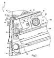
- the second portion 52 of the follower 46 is also configured for engaging the driver blade 16, thus preventing driver blade reciprocation after the last fastener in a fastener strip, or the last fastener in the magazine, has been driven.
- the follower 46 is constructed and arranged so that the front or leading edge 50 enters the passage slot 44 when the last fastener is driven.
- the driver blade 16 has a lower end 56. Once the driver blade 16 returns to a pre-firing position, and upon the driving of the last fastener in the magazine, the leading edge 50 of the follower 46 projects or extends into the nosepiece 20, specifically into the fastener passage slot 44, and the second portion 52 is disposed in close proximity to the driver blade's lower end 56. More specifically, the lower end 56 of the driver blade 16 is preferably disposed approximately 0.025 to 0.10 inch (0,64 to 2,56 mm) from an upper surface 58 of the second portion 52, and most preferably 0.05 inch (1,28 mm) from the lower end, however other spacing is contemplated depending on the situation.
- the second portion 52 is slidably retained in the guide channel 40.
- the shear block 42 has an upper edge 60, and a lower edge 62 of the second portion 52 slidably engages the upper edge once the last fastener is driven. This engagement provides a back-up support for the second portion 52 against the momentum of the driver blade 16.
- a front edge 64 of the second portion 52 extends farther into the driver blade path 18 than the first portion or leading edge 50 of the follower 46. Also, both the first and second portions 50, 52 extend into the driver blade path 18 after the last fastener in the magazine has been driven.
- the follower 46 urges fasteners toward the shear block 42, where they are sequentially driven by the driver blade 16. Once the last fastener has been driven, the leading edge 50 and the second portion 52 of the follower 46 extend into the driver blade path 18, such that the second portion is in close proximity to the lower end 56 of the driver blade 16. In the event the user triggers a tool firing after the magazine 22 is empty, the lower end 56 of the driver blade 16 will impact the second portion 52, and will be prevented from further reciprocal movement. The user will then be alerted to the need for additional fasteners in the magazine 22. Once the follower 46 is retracted in the course of reloading the magazine 22, the tool 10 will be restored to normal operating conditions.
Claims (15)
- Mécanisme pour empêcher le blocage dans un outil d'enfoncement d'éléments de fixation comprenant un magasin (22), un embout (20) et une lame d'enfoncement (16) qui exécute un mouvement alternatif coulissant par rapport à l'embout pour enfoncer des éléments de fixation, comprenant :un suiveur (46) disposé de façon coulissante à l'intérieur du magasin (22) pour pousser des éléments de fixation en direction de l'embout (20),caractérisé en ce que le suiveur (46) comprend une formation pour engager la lame d'enfoncement (16) et empêcher le mouvement alternatif de la lame d'enfoncement après que le dernier élément de fixation dans le magasin ait été enfoncé.
- Mécanisme selon la revendication 1, dans lequel l'embout (20) comprend un bloc de cisaillement (42) qui définit une fente de passage d'élément de fixation (44), et ledit suiveur (46) est conçu et agencé de manière à entrer dans la fente (44) après que le dernier élément de fixation ait été enfoncé.
- Mécanisme selon la revendication 2, dans lequel ledit embout (20) définit un chemin de lame d'enfoncement (18), et un bord avant (50) dudit suiveur (46) s'étend dans ladite fente (44) après que le dernier élément de fixation ait été enfoncé.
- Mécanisme selon la revendication 1, dans lequel ledit suiveur (46) comprend une première partie (50) pour engager la bande d'éléments de fixation, et une deuxième partie (52) pour engager la lame d'enfoncement (16).
- Mécanisme selon la revendication 4, dans lequel ladite deuxième partie (52) s'étend latéralement au-delà de la première partie pour guider ledit suiveur (46) dans le magasin (22).
- Mécanisme selon la revendication 4, dans lequel ledit suiveur (46) est essentiellement en forme de "T" lorsqu'on le regarde de face.
- Mécanisme selon la revendication 4, dans lequel ladite lame d'enfoncement (16) présente une extrémité inférieure (56), et dans une position préalable au tir, une fois que le dernier élément de fixation a été enfoncé, ledit suiveur (46) s'étend dans ledit embout (20) et ladite deuxième partie (52) est disposée dans le voisinage immédiat de ladite extrémité inférieure (56).
- Mécanisme selon la revendication 7, dans lequel une fois que le dernier élément de fixation a été enfoncé, ladite extrémité inférieure (56) de ladite lame d'enfoncement (16) se trouve à une distance d'approximativement 0,025 à 0,1 pouce (0,64 à 2,56 mm) de ladite deuxième partie.
- Mécanisme selon les revendications 2 et 4, dans lequel ledit bloc de cisaillement (42) présente un bord supérieur (60), et dans lequel ladite deuxième partie (52) engage de façon coulissante ledit bord supérieur (60) pour supporter ladite deuxième partie (52) contre le déplacement de ladite lame d'enfoncement (16).
- Outil d'enfoncement d'éléments de fixation, comprenant :le mécanisme selon la revendication 1, dans lequel ledit magasin (22) présente une première extrémité (24) pour recevoir des éléments de fixation, une deuxième extrémité (26) pour délivrer des éléments de fixation à enfoncer, et un canal de guidage (40) ;ledit embout (20) définit une fente de passage d'élément de fixation (44) en communication avec ledit magasin (22) pour recevoir des éléments de fixation en provenance de ladite deuxième extrémité (26), et un passage de lame d'enfoncement (18) en communication avec ladite fente (44) ;ladite lame d'enfoncement (16) exécute un mouvement alternatif coulissant dans ledit chemin de lame d'enfoncement (18), etledit suiveur (46) comprend une première partie (50) pour pousser des éléments de fixation en direction dudit embout (20), et une deuxième partie (52) pour engager ladite lame d'enfoncement (16) et empêcher le mouvement alternatif de la lame d'enfoncement.
- Outil selon la revendication 10, dans lequel ladite partie (52) est engagée de façon coulissante dans ledit canal de guidage (40) et présente un bord avant (64) qui s'étend au-delà d'un bord avant de ladite première partie (50).
- Outil selon la revendication 10, dans lequel ledit embout de pièce (20) comprend un bloc de cisaillement (42) qui présente un bord supérieur (60), et une deuxième partie (52) engage de façon coulissante ledit bord supérieur (60) pour supporter ladite deuxième partie (52) contre le déplacement de ladite lame d'enfoncement (16).
- Outil selon la revendication 10, dans lequel ladite première partie (50) dudit suiveur (46) est alignée avec ladite fente (44) dans ledit embout (20) et s'étend dans ledit chemin de lame d'enfoncement (18) après que le dernier élément de fixation ait été enfoncé.
- Outil selon la revendication 10, dans lequel ladite deuxième partie (52) est déplacée d'une distance comprise entre 0,025 et 0,10 pouce (0,64 à 2,56 mm) à partir d'une extrémité inférieure (56) de ladite lame d'enfoncement (16) après que le dernier élément de fixation ait été enfoncé.
- Outil selon la revendication 10, dans lequel ladite deuxième partie (52) est supportée dans ledit canal de guidage (40) et reçoit une extrémité inférieure (56) de ladite lame d'enfoncement (16) pour empêcher tout mouvement alternatif linéaire supplémentaire après que le dernier élément de fixation ait été enfoncé.
Applications Claiming Priority (2)
| Application Number | Priority Date | Filing Date | Title |
|---|---|---|---|
| US11/091,646 US7328826B2 (en) | 2005-03-28 | 2005-03-28 | Power nailer with driver blade blocking mechanism magazine |
| PCT/US2006/009647 WO2006104721A1 (fr) | 2005-03-28 | 2006-03-16 | Cloueuse electrique dont le magasin est pourvu d'un mecanisme de blocage de la lame d’enfoncement |
Publications (2)
| Publication Number | Publication Date |
|---|---|
| EP1874505A1 EP1874505A1 (fr) | 2008-01-09 |
| EP1874505B1 true EP1874505B1 (fr) | 2008-12-24 |
Family
ID=36572420
Family Applications (1)
| Application Number | Title | Priority Date | Filing Date |
|---|---|---|---|
| EP06738681A Expired - Fee Related EP1874505B1 (fr) | 2005-03-28 | 2006-03-16 | Cloueuse electrique dont le magasin est pourvu d'un mecanisme de blocage de la lame d'enfoncement |
Country Status (11)
| Country | Link |
|---|---|
| US (1) | US7328826B2 (fr) |
| EP (1) | EP1874505B1 (fr) |
| JP (1) | JP4897789B2 (fr) |
| KR (1) | KR20070114275A (fr) |
| CN (1) | CN101132886B (fr) |
| AU (1) | AU2006229799B2 (fr) |
| CA (1) | CA2595952C (fr) |
| DE (1) | DE602006004443D1 (fr) |
| NZ (1) | NZ561965A (fr) |
| TW (1) | TWI339609B (fr) |
| WO (1) | WO2006104721A1 (fr) |
Families Citing this family (19)
| Publication number | Priority date | Publication date | Assignee | Title |
|---|---|---|---|---|
| US8104658B2 (en) * | 2007-11-20 | 2012-01-31 | De Poan Pneumatic Corp. | Block device for nail gun |
| US8181836B2 (en) * | 2008-09-03 | 2012-05-22 | Illinois Tool Works Inc. | Rotary fastener magazine |
| JP5305144B2 (ja) * | 2008-11-28 | 2013-10-02 | 日立工機株式会社 | 釘打機 |
| US8336748B2 (en) * | 2009-09-15 | 2012-12-25 | Robert Bosch Gmbh | Fastener driver with driver assembly blocking member |
| US8746526B2 (en) * | 2009-09-15 | 2014-06-10 | Robert Bosch Gmbh | Fastener driver with blank fire lockout |
| US8061437B2 (en) * | 2010-03-04 | 2011-11-22 | De Poan Pneumatic Corp. | Nail gun with rapidly attachable and detachable magazine assembly |
| US20110278342A1 (en) * | 2010-05-17 | 2011-11-17 | De Poan Pneumatic Corp. | Nail gun with improved attachable and detachable magazine assembly |
| US8292143B2 (en) | 2010-10-12 | 2012-10-23 | Stanley Fastening Systems, L.P. | Dry fire lockout with bypass for fastener driving device |
| US20130320062A1 (en) * | 2012-06-04 | 2013-12-05 | Illinois Tool Works Inc. | Dual channel magazine lockout system |
| WO2016127101A1 (fr) | 2015-02-06 | 2016-08-11 | Milwaukee Electric Tool Corporation | Dispositif d'entraînement de fixation alimenté par ressort à gaz |
| TWM517078U (zh) * | 2015-10-02 | 2016-02-11 | Basso Ind Corp | 具有防護結構之釘槍 |
| US11325235B2 (en) | 2016-06-28 | 2022-05-10 | Black & Decker, Inc. | Push-on support member for fastening tools |
| US11267114B2 (en) | 2016-06-29 | 2022-03-08 | Black & Decker, Inc. | Single-motion magazine retention for fastening tools |
| US11400572B2 (en) * | 2016-06-30 | 2022-08-02 | Black & Decker, Inc. | Dry-fire bypass for a fastening tool |
| US11279013B2 (en) | 2016-06-30 | 2022-03-22 | Black & Decker, Inc. | Driver rebound plate for a fastening tool |
| US10987790B2 (en) | 2016-06-30 | 2021-04-27 | Black & Decker Inc. | Cordless concrete nailer with improved power take-off mechanism |
| US10926385B2 (en) | 2017-02-24 | 2021-02-23 | Black & Decker, Inc. | Contact trip having magnetic filter |
| EP4281253A1 (fr) | 2021-01-20 | 2023-11-29 | Milwaukee Electric Tool Corporation | Dispositif d'entraînement d'élément de fixation électrique |
| CN219726115U (zh) * | 2022-03-15 | 2023-09-22 | 米沃奇电动工具公司 | 用于动力式紧固件驱动器的匣盒 |
Family Cites Families (39)
| Publication number | Priority date | Publication date | Assignee | Title |
|---|---|---|---|---|
| US3606128A (en) | 1967-03-07 | 1971-09-20 | Reich Maschf Gmbh Karl | Percussion machine for fasteners |
| JPS4612800Y1 (fr) * | 1968-03-07 | 1971-05-07 | ||
| JPS573726Y2 (fr) * | 1976-01-13 | 1982-01-23 | ||
| US4197974A (en) * | 1978-06-12 | 1980-04-15 | Speedfast Corporation | Nailer |
| US4197964A (en) * | 1978-08-10 | 1980-04-15 | The Procter & Gamble Company | Starter means for a pop-up type sheet product dispensing package having a restrictive dispensing orifice |
| US4463888A (en) | 1981-04-22 | 1984-08-07 | Duo-Fast Corporation | Fastener driving tool |
| US4597517A (en) | 1985-06-21 | 1986-07-01 | Signode Corporation | Magazine interlock for a fastener driving device |
| DE3608146A1 (de) * | 1986-03-12 | 1987-09-17 | Hilti Ag | Pulverkraftbetriebenes setzgeraet |
| DE3806625A1 (de) | 1988-03-02 | 1989-09-14 | Hilti Ag | Pulverkraftbetriebenes setzgeraet |
| DE68913489T2 (de) * | 1988-12-28 | 1994-06-01 | Mitsui Petrochemical Ind | Verfahren und Gerät zum Herstellen von Rohren mit Löchern. |
| JP2640988B2 (ja) | 1990-11-30 | 1997-08-13 | 株式会社 マキタ | 釘打機における釘の空打防止装置 |
| JPH04133539U (ja) * | 1991-05-30 | 1992-12-11 | 株式会社椿本チエイン | 中空出力軸を具えたレーザ加工機用ワーク回転装置 |
| DE4122873A1 (de) | 1991-07-11 | 1993-01-14 | Hilti Ag | Pulverkraftbetriebenes setzgeraet mit magazin fuer befestigungselemente |
| CA2079417C (fr) * | 1991-10-28 | 2003-01-07 | Lilip Lau | Empreintes extensibles et leur methode de fabrication |
| AU667162B2 (en) | 1993-05-13 | 1996-03-07 | Stanley-Bostitch, Inc. | Fastener driving device particularly suited for use as a roofing nailer |
| DE4406556C1 (de) | 1994-03-01 | 1995-08-03 | Herberg Gmbh & Co Kg | Mit Bolzen bestücktes Magazin für ein pulverkraftbetriebenes Setzgerät |
| JPH07246575A (ja) * | 1994-03-11 | 1995-09-26 | Makita Corp | 釘打機 |
| JP3419535B2 (ja) | 1994-03-11 | 2003-06-23 | 株式会社マキタ | 釘打機 |
| US5836964A (en) * | 1996-10-30 | 1998-11-17 | Medinol Ltd. | Stent fabrication method |
| CA2301351C (fr) * | 1994-11-28 | 2002-01-22 | Advanced Cardiovascular Systems, Inc. | Methode et appareil pour la coupe directe au laser, d'extenseurs metalliques |
| US5744778A (en) * | 1996-04-02 | 1998-04-28 | G&H Diversified Manufacturing, Inc. | Tube handling method and apparatus for cutting machine |
| DE19642295A1 (de) | 1996-10-14 | 1998-04-16 | Hilti Ag | Pulverkraftbetriebenes Setzgerät mit Magazin für Befestigungselemente |
| US5852277A (en) * | 1996-10-24 | 1998-12-22 | Spectralytics, Inc. | Laser cutting tool for cutting elongated hollow workpieces |
| US5906759A (en) * | 1996-12-26 | 1999-05-25 | Medinol Ltd. | Stent forming apparatus with stent deforming blades |
| US5816468A (en) * | 1997-06-24 | 1998-10-06 | Testo Industries Corp. | No-idle-striking structure for nailing machines |
| FR2766403B1 (fr) | 1997-07-25 | 1999-09-17 | Spit Soc Prospect Inv Techn | Bande de bagues de reception de tampon de scellement pour appareil de scellement de tampon |
| US6012622A (en) * | 1998-04-20 | 2000-01-11 | Illinois Tool Works Inc. | Fastener driving tool for trim applications |
| JP3558884B2 (ja) | 1998-08-10 | 2004-08-25 | 株式会社マキタ | 釘打機 |
| EP0987086A3 (fr) | 1998-09-18 | 2000-12-20 | Ramset Fasteners (Aust.) Pty. Ltd. | Outils motorisés comportant un mécanisme d'alimentation du type à chargeur |
| US6036072A (en) | 1998-10-27 | 2000-03-14 | De Poan Pneumatic Corporation | Nailer magazine |
| US6209770B1 (en) | 1999-04-05 | 2001-04-03 | Stanley Fastening Systems, Lp | Safety trip assembly and trip lock mechanism for a fastener driving tool |
| US6056181A (en) | 1999-08-24 | 2000-05-02 | Besco Pneumatic Corp. | Fastening machine |
| US6149046A (en) | 1999-11-01 | 2000-11-21 | Basso Industry Corp. | Safety device for preventing ejecting mechanism from hitting pushing member in a magazine of a power stapler |
| TWM263202U (en) * | 2000-01-13 | 2005-05-01 | Max Co Ltd | Nailing machine |
| US6592014B2 (en) * | 2001-12-13 | 2003-07-15 | Illinois Tool Works Inc. | Lockout mechanism for fastener driving tool |
| US20030121948A1 (en) | 2001-12-31 | 2003-07-03 | Hsien Chen Ming | Device for disabling shooting when nails runs out in a pneumatic nailer |
| CN1389329A (zh) * | 2002-07-03 | 2003-01-08 | 甘仲光 | 自动送钉器 |
| US7021511B2 (en) | 2002-09-18 | 2006-04-04 | Illinois Tool Works Inc. | Lock-out mechanism for powder actuated tool |
| JP4181488B2 (ja) * | 2003-02-07 | 2008-11-12 | 株式会社マキタ | 打ち込み機 |
-
2005
- 2005-03-28 US US11/091,646 patent/US7328826B2/en not_active Expired - Fee Related
-
2006
- 2006-03-16 CN CN2006800064295A patent/CN101132886B/zh not_active Expired - Fee Related
- 2006-03-16 DE DE602006004443T patent/DE602006004443D1/de active Active
- 2006-03-16 EP EP06738681A patent/EP1874505B1/fr not_active Expired - Fee Related
- 2006-03-16 JP JP2008504121A patent/JP4897789B2/ja not_active Expired - Fee Related
- 2006-03-16 CA CA2595952A patent/CA2595952C/fr not_active Expired - Fee Related
- 2006-03-16 NZ NZ561965A patent/NZ561965A/en not_active IP Right Cessation
- 2006-03-16 KR KR1020077019099A patent/KR20070114275A/ko not_active Application Discontinuation
- 2006-03-16 AU AU2006229799A patent/AU2006229799B2/en not_active Ceased
- 2006-03-16 WO PCT/US2006/009647 patent/WO2006104721A1/fr active Application Filing
- 2006-03-23 TW TW095110148A patent/TWI339609B/zh not_active IP Right Cessation
Also Published As
| Publication number | Publication date |
|---|---|
| CN101132886A (zh) | 2008-02-27 |
| WO2006104721A1 (fr) | 2006-10-05 |
| JP4897789B2 (ja) | 2012-03-14 |
| DE602006004443D1 (de) | 2009-02-05 |
| US7328826B2 (en) | 2008-02-12 |
| CA2595952A1 (fr) | 2006-10-05 |
| CN101132886B (zh) | 2010-11-03 |
| AU2006229799A1 (en) | 2006-10-05 |
| EP1874505A1 (fr) | 2008-01-09 |
| TW200635720A (en) | 2006-10-16 |
| CA2595952C (fr) | 2010-09-21 |
| KR20070114275A (ko) | 2007-11-30 |
| JP2008534302A (ja) | 2008-08-28 |
| AU2006229799B2 (en) | 2010-02-11 |
| US20060213946A1 (en) | 2006-09-28 |
| NZ561965A (en) | 2010-12-24 |
| TWI339609B (en) | 2011-04-01 |
Similar Documents
| Publication | Publication Date | Title |
|---|---|---|
| EP1874505B1 (fr) | Cloueuse electrique dont le magasin est pourvu d'un mecanisme de blocage de la lame d'enfoncement | |
| US6592014B2 (en) | Lockout mechanism for fastener driving tool | |
| EP0539138B1 (fr) | Dispositif d'enfoncement d'éléments de fixation avec un mécanisme d'alimentation modifié | |
| CA2422447C (fr) | Outil de charpentage a reglage automatique de la dimension des fixations | |
| US7284685B1 (en) | Pusher bearing and pusher block for magazine feeder | |
| US7506789B2 (en) | Continuous feed cap system | |
| US7000294B2 (en) | Fastener driving tools | |
| EP1230070B1 (fr) | Magasin de clous pour marteau cloueur | |
| US20130320062A1 (en) | Dual channel magazine lockout system | |
| DE60325449D1 (de) | Führungsschienensystem im Magazin für ein Nagelgerät | |
| EP2505314B1 (fr) | Outil de commande | |
| JP2004291101A (ja) | ホッチキス用カートリッジ |
Legal Events
| Date | Code | Title | Description |
|---|---|---|---|
| PUAI | Public reference made under article 153(3) epc to a published international application that has entered the european phase |
Free format text: ORIGINAL CODE: 0009012 |
|
| 17P | Request for examination filed |
Effective date: 20071024 |
|
| AK | Designated contracting states |
Kind code of ref document: A1 Designated state(s): DE FR GB |
|
| 17Q | First examination report despatched |
Effective date: 20080111 |
|
| DAX | Request for extension of the european patent (deleted) | ||
| RBV | Designated contracting states (corrected) |
Designated state(s): DE FR GB |
|
| GRAP | Despatch of communication of intention to grant a patent |
Free format text: ORIGINAL CODE: EPIDOSNIGR1 |
|
| GRAS | Grant fee paid |
Free format text: ORIGINAL CODE: EPIDOSNIGR3 |
|
| GRAA | (expected) grant |
Free format text: ORIGINAL CODE: 0009210 |
|
| AK | Designated contracting states |
Kind code of ref document: B1 Designated state(s): DE FR GB |
|
| REG | Reference to a national code |
Ref country code: GB Ref legal event code: FG4D |
|
| REF | Corresponds to: |
Ref document number: 602006004443 Country of ref document: DE Date of ref document: 20090205 Kind code of ref document: P |
|
| PLBE | No opposition filed within time limit |
Free format text: ORIGINAL CODE: 0009261 |
|
| STAA | Information on the status of an ep patent application or granted ep patent |
Free format text: STATUS: NO OPPOSITION FILED WITHIN TIME LIMIT |
|
| 26N | No opposition filed |
Effective date: 20090925 |
|
| PGFP | Annual fee paid to national office [announced via postgrant information from national office to epo] |
Ref country code: FR Payment date: 20120406 Year of fee payment: 7 |
|
| PGFP | Annual fee paid to national office [announced via postgrant information from national office to epo] |
Ref country code: GB Payment date: 20120326 Year of fee payment: 7 |
|
| PGFP | Annual fee paid to national office [announced via postgrant information from national office to epo] |
Ref country code: DE Payment date: 20120328 Year of fee payment: 7 |
|
| GBPC | Gb: european patent ceased through non-payment of renewal fee |
Effective date: 20130316 |
|
| REG | Reference to a national code |
Ref country code: FR Ref legal event code: ST Effective date: 20131129 |
|
| REG | Reference to a national code |
Ref country code: DE Ref legal event code: R119 Ref document number: 602006004443 Country of ref document: DE Effective date: 20131001 |
|
| PG25 | Lapsed in a contracting state [announced via postgrant information from national office to epo] |
Ref country code: DE Free format text: LAPSE BECAUSE OF NON-PAYMENT OF DUE FEES Effective date: 20131001 Ref country code: FR Free format text: LAPSE BECAUSE OF NON-PAYMENT OF DUE FEES Effective date: 20130402 Ref country code: GB Free format text: LAPSE BECAUSE OF NON-PAYMENT OF DUE FEES Effective date: 20130316 |