EP1874397B2 - Reseau d'electrodes a circuit souple - Google Patents
Reseau d'electrodes a circuit souple Download PDFInfo
- Publication number
- EP1874397B2 EP1874397B2 EP06758862.4A EP06758862A EP1874397B2 EP 1874397 B2 EP1874397 B2 EP 1874397B2 EP 06758862 A EP06758862 A EP 06758862A EP 1874397 B2 EP1874397 B2 EP 1874397B2
- Authority
- EP
- European Patent Office
- Prior art keywords
- flexible circuit
- electrode array
- array
- circuit electrode
- polymer
- Prior art date
- Legal status (The legal status is an assumption and is not a legal conclusion. Google has not performed a legal analysis and makes no representation as to the accuracy of the status listed.)
- Expired - Lifetime
Links
Images


Classifications
-
- A—HUMAN NECESSITIES
- A61—MEDICAL OR VETERINARY SCIENCE; HYGIENE
- A61N—ELECTROTHERAPY; MAGNETOTHERAPY; RADIATION THERAPY; ULTRASOUND THERAPY
- A61N1/00—Electrotherapy; Circuits therefor
- A61N1/02—Details
- A61N1/04—Electrodes
- A61N1/05—Electrodes for implantation or insertion into the body, e.g. heart electrode
- A61N1/0526—Head electrodes
- A61N1/0543—Retinal electrodes
-
- H—ELECTRICITY
- H05—ELECTRIC TECHNIQUES NOT OTHERWISE PROVIDED FOR
- H05K—PRINTED CIRCUITS; CASINGS OR CONSTRUCTIONAL DETAILS OF ELECTRIC APPARATUS; MANUFACTURE OF ASSEMBLAGES OF ELECTRICAL COMPONENTS
- H05K3/00—Apparatus or processes for manufacturing printed circuits
- H05K3/0011—Working of insulating substrates or insulating layers
-
- A—HUMAN NECESSITIES
- A61—MEDICAL OR VETERINARY SCIENCE; HYGIENE
- A61N—ELECTROTHERAPY; MAGNETOTHERAPY; RADIATION THERAPY; ULTRASOUND THERAPY
- A61N1/00—Electrotherapy; Circuits therefor
- A61N1/02—Details
- A61N1/04—Electrodes
- A61N1/05—Electrodes for implantation or insertion into the body, e.g. heart electrode
- A61N1/0526—Head electrodes
- A61N1/0541—Cochlear electrodes
-
- A—HUMAN NECESSITIES
- A61—MEDICAL OR VETERINARY SCIENCE; HYGIENE
- A61N—ELECTROTHERAPY; MAGNETOTHERAPY; RADIATION THERAPY; ULTRASOUND THERAPY
- A61N1/00—Electrotherapy; Circuits therefor
- A61N1/18—Applying electric currents by contact electrodes
- A61N1/32—Applying electric currents by contact electrodes alternating or intermittent currents
- A61N1/36—Applying electric currents by contact electrodes alternating or intermittent currents for stimulation
- A61N1/36046—Applying electric currents by contact electrodes alternating or intermittent currents for stimulation of the eye
-
- Y—GENERAL TAGGING OF NEW TECHNOLOGICAL DEVELOPMENTS; GENERAL TAGGING OF CROSS-SECTIONAL TECHNOLOGIES SPANNING OVER SEVERAL SECTIONS OF THE IPC; TECHNICAL SUBJECTS COVERED BY FORMER USPC CROSS-REFERENCE ART COLLECTIONS [XRACs] AND DIGESTS
- Y10—TECHNICAL SUBJECTS COVERED BY FORMER USPC
- Y10T—TECHNICAL SUBJECTS COVERED BY FORMER US CLASSIFICATION
- Y10T29/00—Metal working
- Y10T29/49—Method of mechanical manufacture
- Y10T29/49002—Electrical device making
- Y10T29/49117—Conductor or circuit manufacturing
- Y10T29/49124—On flat or curved insulated base, e.g., printed circuit, etc.
Definitions
- the present invention is generally directed to neural stimulation and more specifically to an improved electrode array for neural stimulation.
- Foerster investigated the effect of electrically stimulating the exposed occipital pole of one cerebral hemisphere. He found that, when a point at the extreme occipital pole was stimulated, the patient perceived a small spot of light directly in front and motionless (a phosphene). Subsequently, Brindley and Lewin (1968) thoroughly studied electrical stimulation of the human occipital (visual) cortex. By varying the stimulation parameters, these investigators described in detail the location of the phosphenes produced relative to the specific region of the occipital cortex stimulated. These experiments demonstrated: (1) the consistent shape and position of phosphenes; (2) that increased stimulation pulse duration made phosphenes brighter; and (3) that there was no detectable interaction between neighboring electrodes which were as close as 2.4 mm apart.
- Neural tissue can be artificially stimulated and activated by prosthetic devices that pass pulses of electrical current through electrodes on such a device.
- the passage of current causes changes in electrical potentials across visual neuronal membranes, which can initiate visual neuron action potentials, which are the means of information transfer in the nervous system.
- neural tissue stimulation is in the rehabilitation of the blind.
- Some forms of blindness involve selective loss of the light sensitive transducers of the retina.
- Other retinal neurons remain viable, however, and may be activated in the manner described above by placement of a prosthetic electrode device on the inner (toward the vitreous) retinal surface (epiretinal). This placement must be mechanically stable, minimize the distance between the device electrodes and the visual neurons, control the electronic field distribution and avoid undue compression of the visual neurons.
- Bullara US Pat. No. 4,573,481 patented an electrode assembly for surgical implantation on a nerve.
- the matrix was silicone with embedded iridium electrodes.
- the assembly fit around a nerve to stimulate it.
- the Michelson '933 apparatus includes an array of photosensitive devices on its surface that are connected to a plurality of electrodes positioned on the opposite surface of the device to stimulate the retina. These electrodes are disposed to form an array similar to a "bed of nails" having conductors which impinge directly on the retina to stimulate the retinal cells.
- US Patent 4,837,049 to Byers describes spike electrodes for neural stimulation. Each spike electrode pierces neural tissue for better electrical contact.
- US Patent 5,215,088 to Norman describes an array of spike electrodes for cortical stimulation. Each spike pierces cortical tissue for better electrical contact.
- Retinal tacks are one way to attach a retinal electrode array to the retina.
- US Patent 5,109,844 to de Juan describes a flat electrode array placed against the retina for visual stimulation.
- US Patent 5,935,155 to Humayun describes a retinal prosthesis for use with the flat retinal array described in de Juan.
- the invention provides a flexible circuit electrode array as set forth in claim 1 and a method of making the array as set forth in claim 46.
- Polymer materials are useful as electrode array bodies for neural stimulation. They are particularly useful for retinal stimulation to create artificial vision, cochlear stimulation to create artificial hearing, or cortical stimulation for many purposes. Regardless of which polymer is used, the basic construction method is the same. A layer of polymer is laid down, commonly by some form of chemical vapor deposition, spinning, meniscus coating or casting. A layer of metal, preferably platinum, is applied to the polymer and patterned to create electrodes and leads for those electrodes. Patterning is commonly done by photolithographic methods. A second layer of polymer is applied over the metal layer and patterned to leave openings for the electrodes, or openings are created later by means such as laser ablation. Hence the array and its supply cable are formed of a single body. Alternatively, multiple alternating layers of metal and polymer may be applied to obtain more metal traces within a given width.
- the pressure applied against the retina, or other neural tissue, by an electrode array is critical. Too little pressure causes increased electrical resistance between the array and retina, along with electric field dispersion. Too much pressure may block blood flow causing retinal ischemia and hemorrhage. Pressure on the neural retina may also block axonal flow or cause neuronal atrophy leading to optic atrophy.
- Common flexible circuit fabrication techniques such as photolithography generally require that a flexible circuit electrode array be made flat. Since the retina is spherical, a flat array will necessarily apply more pressure near its edges, than at its center. Further, the edges of a flexible circuit polymer array may be quite sharp and cut the delicate retinal tissue. With most polymers, it is possible to curve them when heated in a mold.
- thermoplastic polymer such as liquid crystal polymer
- FIG. 1 shows a perspective view of the implanted portion of the preferred retinal prosthesis.
- a flexible circuit 1 includes a flexible circuit electrode array 10 which is mounted by a retinal tack (not shown) or similar means to the epiretinal surface.
- the flexible circuit electrode array 10 is electrically coupled by a flexible circuit cable 12, which pierces the sclera and is electrically coupled to an electronics package 14, external to the sclera.
- the electronics package 14 is electrically coupled to a secondary inductive coil 16.
- the secondary inductive coil 16 is made from wound wire.
- the secondary inductive coil 16 may be made from a flexible circuit polymer sandwich with wire traces deposited between layers of flexible circuit polymer.
- the electronics package 14 and secondary inductive coil 16 are held together by a molded body 18.
- the molded body 18 may also include suture tabs 20.
- the molded body 18 narrows to form a strap 22 which surrounds the sclera and holds the molded body 18, secondary inductive coil 16, and electronics package 14 in place.
- the molded body 18, suture tabs 20 and strap 22 are preferably an integrated unit made of silicone elastomer.
- Silicone elastomer can be formed in a pre-curved shape to match the curvature of a typical sclera. However, silicone remains flexible enough to accommodate implantation and to adapt to variations in the curvature of an individual sclera.
- the secondary inductive coil 16 and molded body 18 are preferably oval shaped.
- a strap 22 can better support an oval shaped coil.
- the entire implant is attached to and supported by the sclera.
- An eye moves constantly. The eye moves to scan a scene and also has a jitter motion to improve acuity. Even though such motion is useless in the blind, it often continues long after a person has lost their sight.
- eye motion does not cause any flexing which might fatigue, and eventually damage, the device.
- Fig. 2 shows a side view of the implanted portion of the retinal prosthesis, in particular, emphasizing the fan tail 24.
- the secondary inductive coil 16 and molded body 18 must also follow the strap 22 under the lateral rectus muscle on the side of the sclera.
- the implanted portion of the retinal prosthesis is very delicate. It is easy to tear the molded body 18 or break wires in the secondary inductive coil 16.
- the molded body 18 is shaped in the form of a fan tail 24 on the end opposite the electronics package 14.
- the flexible circuit 1 is a made by the following process.
- a layer of polymer such as polyimide, fluoro-polymers, silicone or other polymers
- a support substrate such as glass.
- Layers may be applied by spinning, meniscus coating, casting, sputtering or other physical or chemical vapor deposition, or similar process.
- a metal layer is applied to the polymer.
- the metal is patterned by photolithographic process.
- a photo-resist is applied and patterned by photolithography followed by a wet etch of the unprotected metal.
- the metal can be patterned by lift-off technique, laser ablation or direct write techniques.
- this metal thicker at the electrode and bond pad to improve electrical continuity. This can be accomplished through any of the above methods or electroplating. Then, the top layer of polymer is applied over the metal. Openings in the top layer for electrical contact to the electronics package 14 and the electrodes may be accomplished by laser ablation or reactive ion etching (RIE) or photolithograph and wet etch. Making the electrode openings in the top layer smaller than the electrodes promotes adhesion by avoiding delaminating around the electrode edges.
- RIE reactive ion etching
- the pressure applied against the retina by the flexible circuit electrode array is critical. Too little pressure causes increased electrical resistance between the array and retina. It should be noted that while the present invention is described in terms of application to the retina, the techniques described are equally applicable to many forms of neural stimulation. Application to the retina requires a convex spherical curve. Application to the cochlea requires a constant curve in one dimension and a spiral curve in the other. Application to the cerebral cortex requires a concave spherical curve. Cortical stimulation is useful for artificial vision or hearing, touch and motor control for limb prostheses, deep brain stimulation for Parkinson's disease and multiple sclerosis, and many other applications.
- a flexible circuit electrode array be made flat. Since the retina is spherical, a flat array will necessarily apply more pressure near its edges, than at its center. With most polymers, it is possible to curve them when heated in a mold. By applying the right amount of heat to a completed array, a curve can be induced that matches the curve of the retina. To minimize warping, it is often advantageous to repeatedly heat the flexible circuit in multiple molds, each with a decreasing radius.
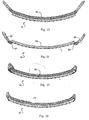
- Fig. 3 illustrates a series of molds according to the preferred embodiment. Since the flexible circuit will maintain a constant length, the curvature must be slowly increased along that length. As the curvature 30 decreases in successive molds ( Figs.
- the straight line length between ends 32 and 34 must decrease to keep the length along the curvature 30 constant, where mold 3E approximates the curvature of the retina or other desired neural tissue.
- the molds provide a further opening 36 for the flexible circuit cable 12 of the array to exit the mold without excessive curvature.
- suitable polymers include thermoplastic materials and thermoset materials. While a thermoplastic material will provide some stretch when heated a thermoset material will not. The successive molds are, therefore, advantageous only with a thermoplastic material. A thermoset material works as well in a single mold as it will with successive smaller molds. It should be noted that, particularly with a thermoset material, excessive curvature in three dimensions will cause the polymer material to wrinkle at the edges. This can cause damage to both the array and the retina. Hence, the amount of curvature is a compromise between the desired curvature, array surface area, and the properties of the material.
- the edges of the polymer layers are often sharp. There is a risk that the sharp edges of a flexible circuit will cut into delicate retinal tissue. It is advantageous to add a soft material, such as silicone, to the edges of a flexible circuit electrode array to round the edges and protect the retina. Silicone around the entire edge may make the flexible circuit less flexible. So, it is advantageous to provide silicone bumpers or ribs to hold the edge of the flexible circuit electrode array away from the retinal tissue. Curvature 40 fits against the retina. The leading edge 44 is most likely to cause damage and is therefore fit with molded silicone bumper. Also, edge 46, where the array lifts off the retina can cause damage and should be fit with a bumper. Any space along the side edges of curvature 40 may cause damage and may be fit with bumpers as well. It is also possible for the flexible circuit cable 12 of the electrode array to contact the retina. It is, therefore, advantageous to add periodic bumpers along the flexible circuit cable 12.
- a soft material such as silicone
- a retinal flexible circuit electrode array must be inside the sclera in order to contact the retina.
- the sclera is cut through at the pars plana, forming a sclerotomy, and the flexible circuit passed through the sclerotomy.
- a flexible circuit is thin but wide. The more electrode wires, the wider the flexible circuit must be. It may be difficult to seal a sclerotomy over a flexible circuit wide enough to support enough wires for a high resolution array. A narrow sclerotomy is preferable.
- Fig. 5 depicts a further embodiment of the part of the prosthesis shown in Fig. 4 with a fold A between the circuit electrode array 10 and the flexible circuit cable 12.
- the angle in the fold A also called ankle has an angle of 1°-180°, preferably 80°-120°.
- the fold A is advantageous since it reduces tension and enables an effective attachment of the flexible electrode circuit array 10 to the retina.
- Fig. 6 depicts a side view of the prosthesis insight of the eye with an angle K of the flexible circuit cable 12 and a fold A between the circuit electrode array 10 and the flexible circuit cable 12.
- the angle K is about 45°-180° and preferably 80°-100°.
- the fold K also called knee is advantageous because it decreases pressure which would be applied by the flexible circuit cable 10.
- Fig. 7 shows the implanted portion of the retinal prosthesis including the additional feature of a gentle twist or fold 48 in the flexible circuit cable 12, where the flexible circuit cable 12 passes through the sclera (sclerotomy).
- the twist may be a simple sharp twist, or fold 48; or it may be a longer twist, forming a tube. While the tube is rounder, it reduces the flexibility of the flexible circuit.
- a simple fold 48 reduces the width of the flexible circuit with only minimal impact on flexibility.
- silicone or other pliable substance may be used to fill the center of the tube or fold 48 formed by the twisted flexible circuit cable 12. Further it is advantageous to provide a sleeve or coating 50 that promotes healing of the sclerotomy.
- Polymers such as polyimide, which may be used to form the flexible circuit cable 12 and flexible circuit electrode array 10, are generally very smooth and do not promote a good bond between the flexible circuit cable 12 and scleral tissue.
- a sleeve or coating of polyester, collagen, silicone, Gore-tex or similar material would bond with scleral tissue and promote healing. In particular, a porous material will allow scleral tissue to grow into the pores promoting a good bond.
- the flexible circuit electrode array 10 may be inserted through the sclera, behind the retina and placed between the retina and choroid to stimulate the retina subretinally.
- the stop may be widening of the flexible circuit 1 or it may be added material such as a bumper or sleeve.
- Human vision provides a field of view that is wider than it is high. This is partially due to fact that we have two eyes, but even a single eye provides a field of view that is approximately 90° high and 140° to 160° degrees wide. It is therefore, advantageous to provide a flexible circuit electrode array 10 that is wider than it is tall. This is equally applicable to a cortical visual array. In which case, the wider dimension is not horizontal on the visual cortex, but corresponds to horizontal in the visual scene.
- Fig. 8 shows the flexible circuit electrode array prior to folding and attaching the array to the electronics package 14.
- an interconnection pad 52 for connection to the electronics package 14.
- the flexible circuit electrode array 10 At the other end of the flexible circuit cable 12 is the flexible circuit electrode array 10.
- an attachment point 54 is provided near the flexible circuit electrode array 10.
- a retina tack (not shown) is placed through the attachment point 54 to hold the flexible circuit electrode array 10 to the retina.
- a stress relief 55 is provided surrounding the attachment point 54.
- the stress relief 55 may be made of a softer polymer than the flexible circuit, or it may include cutouts or thinning of the polymer to reduce the stress transmitted from the retina tack to the flexible circuit electrode array 10.
- the flexible circuit cable 12 is formed in a dog leg pattern so than when it is folded at fold 48 it effectively forms a straight flexible circuit cable 12 with a narrower portion at the fold 48 for passing through the sclerotomy.
- Fig. 9 shows the flexible circuit electrode array after the flexible circuit cable 12 is folded at the fold 48 to form a narrowed section.
- the flexible circuit cable 12 may include a twist or tube shape as well.
- the bond pad 52 for connection to the electronics package 14 and the flexible circuit electrode array 10 are on opposite side of the flexible circuit. This requires patterning, in some manner, both the base polymer layer and the top polymer layer.
- the openings for the bond pad 52 and the electrodes are on the top polymer layer and only the top polymer layer needs to be patterned.
- the narrowed portion of the flexible circuit cable 12 pierces the sclera, shoulders formed by opposite ends of the narrowed portion help prevent the flexible circuit cable 12 from moving through the sclera. It may be further advantageous to add ribs or bumps of silicone or similar material to the shoulders to further prevent the flexible circuit cable 12 from moving through the sclera.
- a suture tab 56 in the flexible circuit body near the electronics package to prevent any movement in the electronics package from being transmitted to the flexible circuit electrode array 10.
- a segment of the flexible circuit cable 12 can be reinforced to permit it to be secured directly with a suture.
- a skirt 60 covers the flexible circuit electrode array 10, and extends beyond its edges. It is further advantageous to include wings 62 adjacent to the attachment point 54 to spread any stress of attachment over a larger area of the retina. There are several ways of forming and bonding the skirt 60.
- the skirt 60 may be directly bonded through surface activation or indirectly bonded using an adhesive.
- a flexible circuit electrode array 10 may be layered using different polymers for each layer. Using too soft of a polymer may allow too much stretch and break the metal traces. Too hard of a polymer may cause damage to delicate neural tissue. Hence a relatively hard polymer, such a polyimide may be used for the bottom layer and a relatively softer polymer such a silicone may be used for the top layer including an integral skirt to protect delicate neural tissue.
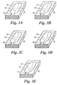
- the simplest solution is to bond the skirt 60 to the back side (away from the retina) of the flexible circuit electrode array 10 as shown in Fig. 11 . While this is the simplest mechanical solution, sharp edges of the flexible circuit electrode array 10 may contact the delicate retina tissue. Bonding the.skirt to the front side (toward the retina) of the flexible circuit electrode array 10, as shown in Fig. 12 , will protect the retina from sharp edges of the flexible circuit electrode array 10. However, a window 62 must be cut in the skirt 60 around the electrodes. Further, it is more difficult to reliably bond the skirt 60 to the flexible circuit electrode array 10 with such a small contact area. This method also creates a space between the electrodes and the retina which will reduce efficiency and broaden the electrical field distribution of each electrode. Broadening the electric field distribution will limit the possible resolution of the flexible circuit electrode array 10.
- Fig. 13 shows another structure where the skirt 60 is bonded to the back side of the flexible circuit electrode array 10, but curves around any sharp edges of the flexible circuit electrode array 10 to protect the retina. This gives a strong bond and protects the flexible circuit electrode array 10 edges. Because it is bonded to the back side and molded around the edges, rather than bonded to the front side, of the flexible circuit electrode array 10, the portion extending beyond the front side of the flexible circuit electrode array 10 can be much smaller. This limits any additional spacing between the electrodes and the retinal tissue.
- Fig. 14 shows a flexible circuit electrode array 10 similar to Fig. 13 , with the skirt 60, flush with the front side of the flexible circuit electrode array 10 rather than extending beyond the front side. While this is more difficult to manufacture, it does not lift the electrodes off the retinal surface as with the array in Fig. 10 . It should be noted that Figs. 11, 13, and 14 show skirt 60 material along the back of the flexible circuit electrode array 10 that is not necessary other than for bonding purposes. If there is sufficient bond with the flexible circuit electrode array 10, it may advantageous to thin or remove portions of the skirt 60 material for weight reduction.
- the flexible circuit electrode array 10 is manufactured in layers.
- a base layer of polymer 70 is laid down, commonly by some form of chemical vapor deposition, spinning, meniscus coating or casting.
- a layer of metal 72 (preferably platinum) is applied to the polymer base layer 70 and patterned to create electrodes 74 and traces for those electrodes. Patterning is commonly done by photolithographic methods.
- the electrodes 74 may be built up by electroplating or similar method to increase the surface area of the electrode 74 and to allow for some reduction in the electrodes 74 over time. Similar plating may also be applied to the bond pads 52 ( fig. 8-10 ).
- a top polymer layer 76 is applied over the metal layer 72 and patterned to leave openings for the electrodes 74, or openings are created later by means such as laser ablation. It is advantageous to allow an overlap of the top polymer layer 76 over the electrodes 74 to promote better adhesion between the layers, and to avoid increased electrode reduction along their edges.
- the overlapping top layer promotes adhesion by forming a clamp to hold the metal electrode between the two polymer layers.
- multiple alternating layers of metal and polymer may be applied to obtain more metal traces within a given width.
- FIG. 16 depicts the flexible circuit array 12 before it is folded and attached to the implanted portion containing an additional fold A between the flexible electrode array 12 and the flexible cable 10.
- the angle in the fold A also called ankle has an angle of 1°-180°, preferably 80°-120°.
- the ankle is advantageous in the process of inserting the prostheses in the eye and attaching it to the retina.
- FIG. 17 depicts the flexible circuit array 12 FIG. 16 folded containing an additional fold A between the flexible electrode array 12 and the flexible cable 10.
- the flexible circuit array as shown in FIGS. 8 and 16 differ by the fold A from each other.
- FIG. 18 depicts a flexible circuit array of FIG. 17 with a protective skirt 60 and containing an additional fold A between the flexible electrode array and the flexible cable.
- the flexible circuit array as shown in FIGS. 10 and 18 differ by the fold A from each other.
- FIG. 19 depicts a top view of a flexible circuit array and flexible circuit cable showing the additional horizontal angel H between the flexible electrode array 12 and the flexible cable 10.
- the angle H is from about 1° to about 90° and preferably from about 30° to about 60°.
- FIG. 20 depicts another variation without the horizontal angel H between the flexible electrode array 12 and the flexible cable 10 but with an orientation of the electrodes in the flexible electrode array 12 as shown in FIG. 19 for a flexible electrode array 12.
- the grid of electrodes 13 has the angle H with the flexible cable which can be the same as the angel H in the flexible electrode array 12 of FIG. 19 .
- both variation shown in FIGS. 19 and 20 have the advantage that the electrodes are oriented horizontally if they are inserted into the eye. Further, both variations as shown in FIGS. 19 and 20 can also additionally contain a fold K.
- FIG. 21 depicts a top view of a flexible circuit array and flexible circuit cable as shown in FIGS. 10 and 18 wherein the array contains a slit along the length axis.
- FIG. 22 depicts a skirt of silicone or other pliable material as shown in Fig. 10 to 14 .
- a skirt 60 covers the flexible circuit electrode array 10, and extends beyond its edges.
- the flexible circuit electrode array contains a slit 80 along the lengths axis.
- the skirt of silicone or other pliable material contains preferably at least two attachment points 81 and stress reliefs 82 are provided surrounding the attachment points 81.
- the attachment points 81 are located preferably on the skirt 60 outside the flexible circuit electrode 10 and are positioned apart as far as possible from each other.
- the two tacks 81 are far enough apart not to cause tenting, therefore fibrosis between the two tacks which cause a traction detachment of the retina.
- the polyimide is completely between the two tacks, which also reduce the possibility of tenting. Also, this orientation of tacks keeps the tacks away from the axons, which arise from the ganglion cells which are tried to be activated. They are away from the raffe.
- the wings act like external tabs or strain relieves. The multiple tacks prevent rotation of the array.
- the stress relief 82 may be made of a softer polymer than the flexible circuit, or it may include cutouts or thinning of the polymer to reduce the stress transmitted from the retina tack to the flexible circuit electrode array 10.
- FIG. 23 depicts a flexible circuit array 10 with a protective skirt 60 bonded to the back side of the flexible circuit array 10 with a progressively decreasing radius.
- FIG. 24 depicts a flexible circuit array 10 with a protective skirt 60 bonded to the front side of the flexible circuit array 10 with a progressively decreasing radius.
- FIG. 25 depicts a flexible circuit array 10 with a protective skirt 60 bonded to the back side of the flexible circuit array 10 and molded around the edges of the flexible circuit array with a progressively decreasing radius.
- FIG. 26 depicts a flexible circuit array 10 with a protective skirt 60 bonded to the back side of the flexible circuit array 10 and molded around the edges of the flexible circuit array and flush with the front side of the array with a progressively decreasing radius.
- FIG. 27 depicts a side view of the array with a skirt 60 containing a grooved and rippled pad 56a instead a suture tab 56.
- This pad 56a has the advantage of capturing a mattress suture 57.
- a mattress suture 57 has the advantage of holding the grove or rippled pad 56a in two places as shown in FIG. 28 .
- Each suture 57 is fixed on the tissue on two places 59.
- a mattress suture 57 on a grooved or rippled mattress 56a therefore provides a better stability.
- FIG. 29 depicts a flexible circuit array 10 with a protective skirt 60 bonded to the front side of the flexible circuit array 10 with individual electrode 13 windows and with material, preferably silicon between the electrodes 13.
- FIG. 30 depicts a flexible circuit array with a protective skirt bonded to the back side of the flexible circuit array and molded around the edges of the flexible circuit array with individual electrode windows and with material, preferably silicon between the electrodes 13.
- FIGS 31-36 show several surfaces to be applied on top of the cable.
- the surfaces are thin films containing a soft polymer, preferably silicone.
- FIG. 31 shows a flange 15: A flange 15 can be a solid film of material containing silicone added to the surface of the polymer containing polyimide.
- FIGS. 32-34 show a ladder 15a: A ladder 15a is a flange with material removed from central portions in some shape 19.
- FIG. 35 shows a skeleton structure 15b.
- a skeleton15b is a flange with material removed from perimeter portions in some shape 21.
- FIG. 36 shows a structure 15c with beads 23 and bumpers 25.
- a bead 23 is material added to perimeter portions of the polymer cable in some shape without material being added on the central area.
- a bumper 25 can be an extended or continuous version of the beaded approach. Both approaches are helpful in preventing any possible injury of the tissue by the polymer.
- FIG. 37 depicts the top view of the flexible circuit array 10 being enveloped within an insulating material 11.
- the electrode array 10 comprises oval-shaped electrode array body 10, a plurality of electrodes 13 made of a conductive material, such as platinum or one of its alloys, but that can be made of any conductive biocompatible material such as iridium, iridium oxide or titanium nitride.
- the electrode array 10 is enveloped within an insulating material 11 that is preferably silicone.
- "Oval-shaped" electrode array body means that the body may approximate either a square or a rectangle shape, but where the corners are rounded. This shape of an electrode array is described in the U.S. Patent Application No. 20020111658 , entitled “Implantable retinal electrode array configuration for minimal retinal damage and method of reducing retinal stress” and No. 20020188282 , entitled “Implantable drug delivery device” to Rober J. Greenberg et al.
- the material body 11 is made of a soft material that is compatible with the electrode array body 10.
- the body 11 made of silicone having hardness of about 50 or less on the Shore A scale as measured with a durometer. In an alternate embodiment the hardness is about 25 or less on the Shore A scale as measured with a durometer.
- FIG. 38 depicts a cross-sectional view of the flexible circuit array 10 being enveloped within an insulating material 11. It shows how the edges of the material body 11 are lift off due to the contracted radius.
- the electrode array 10 preferably also contains a fold A between the cable 12 and the electrode array 10. The angle of the fold A secures a relief of the implanted material.
- FIG. 39 depicts a cross-sectional view of the flexible circuit array 10 being enveloped within an insulating material 11 with open electrodes 13 and the material 11 between the electrodes 13. This embodiment also has relief between the body 10 and the retinal R.
- FIG. 40 depicts a cross-sectional view of the flexible circuit array 10 being enveloped within an insulating material 11 with open electrodes 13. This is another embodiment wherein the electrodes 13 are not separated by the material 11 but the material 11 is extended so that the electrodes 13 are prevented of direct contact with the retina R.
- FIG. 41 depicts a cross-sectional view of the flexible circuit array 10being enveloped within an insulating material 11 with electrodes 13 on the surface of the material 11.
- This is a further embodiment with the electrode 13 on the surface of the material 11, preferably silicone.
- the embodiments shown in FIGS. 39, 40, and 41 show a preferred body 11 containing silicone with the edges being lift off from the retina due to contracted radius of the silicon body 11.
- FIG. 42 depicts a cross-sectional view of the flexible circuit array 10 being enveloped within an insulating material 11 with electrodes 13 on the surface of the material 11 insight the eye with an angle K in the fold of the flexible circuit cable 12 and a fold A between the circuit electrode array 10 and the flexible circuit cable 12.
- the material 11 and electrode array body 10 are in intimate contact with retina R.
- the surface of electrode array body 10 in contact with retina R is a curved surface with a contracted radius compared to the spherical curvature of retina R to minimize stress concentrations therein.
- the decreasing radius of spherical curvature of material 11 near its edge forms edge relief that causes the edges of the body 11 to lift off the surface of retina R eliminating stress concentrations.
- the edges of body 11 are strongly lifted off due to the contracted radius of the body 11.
- the edge of body 11 has a rounded edge eliminating stress and cutting of retina R.
- FIG. 43 shows a part of the FIG. 42 enlarged showing the electrode array 10 and the electrodes 13 enveloped by the polymer material, preferably silicone 11 being attached to the retina R.
- the electrode array 10 embedded in or enveloped by the polymer material, preferably silicone 11 can be preferably produced through the following steps.
- the soft polymer material which contains silicone is molded into the designed shape and partially hardened.
- the electrode array 10 which preferably contains polyimide is introduced and positioned in the partially hardened soft polymer containing silicone.
- the soft polymer 11 containing silicone is fully hardened in the designed shape enveloping the electrode array 10.
- the polymer body 11 has a shape with a contracted radius compared with the retina R so that the edges of the body 11 lift off from the retina R.
- FIGs. 44 - 46 show application of the present invention to a cochlear prosthesis.
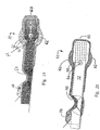
- Figure 44 shows of front view of cochlear electrode array 110.
- the cochlear electrode array 110 tapers toward the top to fit in an ever smaller cochlea and because less width is required toward the top for metal traces.
- the electrodes 174 are arranged linearly along the length of the array 110. Further a skirt 160 of more compliant polymer, such as silicone surrounds the array 110.
- Figure 45 is a side view of the cochlear electrode array 110.
- the cochlear electrode array 110 includes a bottom polymer layer 170, metal traces 172 and a top polymer layer 176. Openings in the top polymer layer 176 define electrodes 174.
- the cochlear electrode array 110 is made flat as shown if figures 44 and 13B . It is then thermoformed, as described above, into a spiral shape to approximate the shape of the cochlea, as shown in Figure 46 .
- the cochlear electrode array 110 is implanted with the bottom layer 170 formed toward the outside of the curvature, and the top polymer layer 176 toward the inside of the curvature. This is opposite of the thermoforming process used for a retinal array.
- a cortical array would be thermoformed to curve inward like a cochlear array.
Landscapes
- Health & Medical Sciences (AREA)
- Engineering & Computer Science (AREA)
- Life Sciences & Earth Sciences (AREA)
- Animal Behavior & Ethology (AREA)
- Cardiology (AREA)
- Biomedical Technology (AREA)
- Nuclear Medicine, Radiotherapy & Molecular Imaging (AREA)
- Radiology & Medical Imaging (AREA)
- Ophthalmology & Optometry (AREA)
- Heart & Thoracic Surgery (AREA)
- General Health & Medical Sciences (AREA)
- Public Health (AREA)
- Veterinary Medicine (AREA)
- Manufacturing & Machinery (AREA)
- Microelectronics & Electronic Packaging (AREA)
- Prostheses (AREA)
Claims (11)
- Réseau d'électrodes de circuit souple (10) destiné à la stimulation d'un tissu nerveux, comprenant :une couche de base polymère (70) ;des traces de métal (72) déposées sur ladite couche de base polymère (70), comprenant des électrodes (13, 74) adaptées pour stimuler un tissu nerveux ; etune couche supérieure polymère (76) déposée sur ladite couche de base polymère (70) et lesdites traces de métal,le réseau d'électrodes (10) est pré-incurvé en une forme sphérique convexe sur le plan des électrodes (13, 74) afin de s'adapter à la courbure de la rétine.
- Réseau d'électrodes de circuit souple (10) selon la revendication 1, dans lequel ladite couche de base polymère (70), lesdites traces de métal (72) et ladite couche supérieure polymère (76) sont thermoformées en une forme sphérique.
- Réseau d'électrodes de circuit souple (10) selon la revendication 1, dans lequel ladite couche supérieure polymère (76) est un polymère plus souple que ladite couche de base polymère (70).
- Réseau d'électrodes de circuit souple (10) selon la revendication 1, comprenant en outre une membrane de détente (55, 82) adaptée pour la fixation dudit réseau d'électrodes de circuit souple (10), dans lequel ladite membrane de détente (55, 82) est un matériau plus souple que ladite couche de base polymère (70).
- Réseau d'électrodes de circuit souple (10) selon la revendication 1, comprenant en outre une partie rétrécie dans une partie de câble de circuit souple (12) dudit réseau d'électrodes de circuit souple (10).
- Réseau d'électrodes de circuit souple (10) selon la revendication 5, dans lequel ladite partie rétrécie est adaptée pour percer une sclère.
- Réseau d'électrodes de circuit souple (10) selon la revendication 1, comprenant en outre un pli diagonal (48) dans une partie de câble de circuit souple (12) dudit réseau d'électrodes de circuit souple (10).
- Réseau d'électrodes de circuit souple (10) selon la revendication 7, dans lequel ledit pli diagonal (48) traverse un coude dans ledit réseau d'électrodes de circuit souple (10).
- Réseau d'électrodes de circuit souple (10) selon la revendication 7, comprenant en outre des plots de liaison (52) couplés auxdites traces de métal (72) sur une extrémité dudit réseau d'électrodes de circuit souple (10) opposée auxdites électrodes (13, 74), et des ouvertures dans ladite couche supérieure polymère (76) pour lesdites électrodes (13, 74) et lesdits plots de liaison (52).
- Réseau d'électrodes de circuit souple (10) selon la revendication 7, dans lequel ledit pli (48) forme une partie rétrécie.
- Réseau d'électrodes de circuit souple (10) selon la revendication 1, comprenant en outre une partie élargie d'une partie de câble de circuit souple (12) dudit réseau d'électrodes de circuit souple (10) adaptée pour résister au mouvement dudit réseau d'électrodes de circuit souple (10).
Priority Applications (2)
| Application Number | Priority Date | Filing Date | Title |
|---|---|---|---|
| EP20100182995 EP2298408A3 (fr) | 2005-04-28 | 2006-04-28 | Réseau d'électrodes à circuit souple |
| EP10179429.5A EP2286871B1 (fr) | 2005-04-28 | 2006-04-28 | Procédé de fabricaton d'un reseau d'electrodes a circuit souple |
Applications Claiming Priority (3)
| Application Number | Priority Date | Filing Date | Title |
|---|---|---|---|
| US67600805P | 2005-04-28 | 2005-04-28 | |
| US11/207,644 US8014878B2 (en) | 2005-04-28 | 2005-08-19 | Flexible circuit electrode array |
| PCT/US2006/016655 WO2006116765A2 (fr) | 2005-04-28 | 2006-04-28 | Reseau d'electrodes a circuit souple |
Related Child Applications (3)
| Application Number | Title | Priority Date | Filing Date |
|---|---|---|---|
| EP10179429.5A Division-Into EP2286871B1 (fr) | 2005-04-28 | 2006-04-28 | Procédé de fabricaton d'un reseau d'electrodes a circuit souple |
| EP10179429.5A Division EP2286871B1 (fr) | 2005-04-28 | 2006-04-28 | Procédé de fabricaton d'un reseau d'electrodes a circuit souple |
| EP20100182995 Division-Into EP2298408A3 (fr) | 2005-04-28 | 2006-04-28 | Réseau d'électrodes à circuit souple |
Publications (3)
| Publication Number | Publication Date |
|---|---|
| EP1874397A2 EP1874397A2 (fr) | 2008-01-09 |
| EP1874397B1 EP1874397B1 (fr) | 2016-06-01 |
| EP1874397B2 true EP1874397B2 (fr) | 2019-12-25 |
Family
ID=37024695
Family Applications (3)
| Application Number | Title | Priority Date | Filing Date |
|---|---|---|---|
| EP20100182995 Withdrawn EP2298408A3 (fr) | 2005-04-28 | 2006-04-28 | Réseau d'électrodes à circuit souple |
| EP10179429.5A Expired - Lifetime EP2286871B1 (fr) | 2005-04-28 | 2006-04-28 | Procédé de fabricaton d'un reseau d'electrodes a circuit souple |
| EP06758862.4A Expired - Lifetime EP1874397B2 (fr) | 2005-04-28 | 2006-04-28 | Reseau d'electrodes a circuit souple |
Family Applications Before (2)
| Application Number | Title | Priority Date | Filing Date |
|---|---|---|---|
| EP20100182995 Withdrawn EP2298408A3 (fr) | 2005-04-28 | 2006-04-28 | Réseau d'électrodes à circuit souple |
| EP10179429.5A Expired - Lifetime EP2286871B1 (fr) | 2005-04-28 | 2006-04-28 | Procédé de fabricaton d'un reseau d'electrodes a circuit souple |
Country Status (4)
| Country | Link |
|---|---|
| US (5) | US8014878B2 (fr) |
| EP (3) | EP2298408A3 (fr) |
| AU (1) | AU2006239178B2 (fr) |
| WO (1) | WO2006116765A2 (fr) |
Families Citing this family (79)
| Publication number | Priority date | Publication date | Assignee | Title |
|---|---|---|---|---|
| US8014878B2 (en) | 2005-04-28 | 2011-09-06 | Second Sight Medical Products, Inc. | Flexible circuit electrode array |
| WO2008103195A2 (fr) | 2005-04-28 | 2008-08-28 | Second Sight Medical Products, Inc. | Réseau d'électrodes de circuit souple |
| US7877866B1 (en) * | 2005-10-26 | 2011-02-01 | Second Sight Medical Products, Inc. | Flexible circuit electrode array and method of manufacturing the same |
| US20070198066A1 (en) * | 2005-11-03 | 2007-08-23 | Greenberg Robert J | Method and apparatus for visual neural stimulation |
| US7914842B1 (en) * | 2006-02-10 | 2011-03-29 | Second Sight Medical Products, Inc | Method of manufacturing a flexible circuit electrode array |
| US8190266B2 (en) * | 2006-02-15 | 2012-05-29 | Dohey Eye Institute | Wide-field retinal prosthesis |
| US9185810B2 (en) * | 2006-06-06 | 2015-11-10 | Second Sight Medical Products, Inc. | Molded polymer comprising silicone and at least one metal trace and a process of manufacturing the same |
| AU2007261384B2 (en) * | 2006-06-19 | 2011-08-04 | Second Sight Medical Products, Inc. | Electrode with increased stability and method of manufacturing the same |
| AU2012202198B2 (en) * | 2006-06-21 | 2012-08-23 | Second Sight Medical Products, Inc. | Flexible circuit electrode array with at least one tack opening |
| AU2007261319B2 (en) * | 2006-06-21 | 2012-02-09 | Second Sight Medical Products, Inc. | Flexible circuit electrode array with at least one tack opening |
| WO2008013879A2 (fr) * | 2006-07-26 | 2008-01-31 | Second Sight Medical Products, Inc. | Procédé pour une protection cathodique de matières d'électrode |
| AU2007284422B2 (en) | 2006-08-18 | 2011-06-02 | Second Sight Medical Products, Inc. | Package for an implantable neural stimulation device |
| WO2008042278A2 (fr) * | 2006-09-29 | 2008-04-10 | Second Sight Medical Products, Inc. | Procédé de mesure de l'impédance stable et reproductible électrode-tissus |
| AU2007309232B2 (en) | 2006-10-19 | 2013-09-26 | Second Sight Medical Products, Inc. | Visual prosthesis |
| US8244363B2 (en) * | 2006-10-20 | 2012-08-14 | Second Sight Medical Products, Inc. | Visual prosthesis |
| US8010202B2 (en) * | 2006-11-20 | 2011-08-30 | Second Sight Medical Products, Inc. | Method of improving electrode tissue interface |
| US7831309B1 (en) | 2006-12-06 | 2010-11-09 | University Of Southern California | Implants based on bipolar metal oxide semiconductor (MOS) electronics |
| WO2008101225A2 (fr) * | 2007-02-16 | 2008-08-21 | Second Sight Medical Products, Inc. | Ensemble d'électrodes à circuit flexible avec support de film ou fil |
| EP2134415B1 (fr) | 2007-03-08 | 2017-05-03 | Second Sight Medical Products, Inc. | Réseau d'électrodes en circuit flexible |
| US20090082839A1 (en) * | 2007-06-26 | 2009-03-26 | Zurlin Technologies Holdings, Llc | Electronic anti-snoring and sleep apnea device for sleep-breathing disorders, electronic anti-bruxing device, and electronic device for TMD therapy |
| US9592377B2 (en) | 2007-07-27 | 2017-03-14 | Second Sight Medical Products, Inc. | Implantable device for the brain |
| US8874239B2 (en) | 2007-11-08 | 2014-10-28 | Second Sight Medical Products, Inc. | Cochlear stimulation device |
| US8250745B1 (en) | 2008-01-24 | 2012-08-28 | Advanced Bionics, Llc | Process for manufacturing a microcircuit cochlear electrode array |
| TWI356691B (en) * | 2008-02-19 | 2012-01-21 | Ind Tech Res Inst | Artificial optic nerve, artificial retina chip mod |
| EP2265321B8 (fr) * | 2008-03-04 | 2018-12-19 | Second Sight Medical Products, Inc. | Réseau d'électrodes pour une pression neurale régulière |
| US7912556B2 (en) * | 2008-03-04 | 2011-03-22 | Second Sight Medical Products, Inc. | Electrode array for even neural pressure |
| US20090270958A1 (en) * | 2008-04-25 | 2009-10-29 | Greenberg Robert J | Simply Supported Neural Stimulation Electrode Array for Applying Pressure on Neural Tissue |
| US8442641B2 (en) | 2010-08-06 | 2013-05-14 | Nano-Retina, Inc. | Retinal prosthesis techniques |
| US8428740B2 (en) | 2010-08-06 | 2013-04-23 | Nano-Retina, Inc. | Retinal prosthesis techniques |
| US8150526B2 (en) | 2009-02-09 | 2012-04-03 | Nano-Retina, Inc. | Retinal prosthesis |
| US8706243B2 (en) | 2009-02-09 | 2014-04-22 | Rainbow Medical Ltd. | Retinal prosthesis techniques |
| US8718784B2 (en) | 2010-01-14 | 2014-05-06 | Nano-Retina, Inc. | Penetrating electrodes for retinal stimulation |
| EP2401028A1 (fr) | 2009-02-27 | 2012-01-04 | IMI Intelligent Medical Implants AG | Prothèse visuelle et dispositif de stimulation rétinienne associé |
| US9950166B2 (en) | 2009-10-20 | 2018-04-24 | Nyxoah SA | Acred implant unit for modulation of nerves |
| US10751537B2 (en) | 2009-10-20 | 2020-08-25 | Nyxoah SA | Arced implant unit for modulation of nerves |
| US9409013B2 (en) | 2009-10-20 | 2016-08-09 | Nyxoah SA | Method for controlling energy delivery as a function of degree of coupling |
| US10806926B2 (en) * | 2009-10-20 | 2020-10-20 | Man & Science Sa | Implantable electrical stimulator |
| WO2011075480A2 (fr) * | 2009-12-18 | 2011-06-23 | Advanced Bionics, Llc | Réseau d'électrodes cochléaires |
| US8332052B1 (en) | 2010-03-18 | 2012-12-11 | Advanced Bionics | Microcircuit cochlear electrode array and method of manufacture |
| EP2658444B1 (fr) | 2010-12-30 | 2014-11-05 | Roche Diagnostics GmbH | Procédé de mise au point d'un biocapteur efficace, ainsi que biocapteur, substrat et kit d'introduction correspondants |
| US8571669B2 (en) | 2011-02-24 | 2013-10-29 | Nano-Retina, Inc. | Retinal prosthesis with efficient processing circuits |
| WO2012158834A1 (fr) | 2011-05-16 | 2012-11-22 | Second Sight Medical Products, Inc. | Interface corticale pourvue d'une rangée d'électrodes divisée en doigts séparés et/ou d'un émetteur-récepteur sans fil |
| WO2013046040A2 (fr) | 2011-09-30 | 2013-04-04 | Adi Mashiach | Appareil et procédé de commande d'un apport d'énergie en fonction d'un degré de couplage |
| US10052097B2 (en) | 2012-07-26 | 2018-08-21 | Nyxoah SA | Implant unit delivery tool |
| US11253712B2 (en) | 2012-07-26 | 2022-02-22 | Nyxoah SA | Sleep disordered breathing treatment apparatus |
| US9907967B2 (en) | 2012-07-26 | 2018-03-06 | Adi Mashiach | Transcutaneous power conveyance device |
| EP3539612B1 (fr) | 2012-07-26 | 2024-09-04 | Nyxoah SA | Encapsulation d'implant |
| EP2890342B1 (fr) * | 2012-08-29 | 2017-07-05 | The Bionics Institute of Australia | Conduite électrique pour connecter un dispositif implantable dans l'oeil à une interface externe à l'oeil |
| US9370417B2 (en) | 2013-03-14 | 2016-06-21 | Nano-Retina, Inc. | Foveated retinal prosthesis |
| US11229789B2 (en) | 2013-05-30 | 2022-01-25 | Neurostim Oab, Inc. | Neuro activator with controller |
| EP3441109A1 (fr) | 2013-05-30 | 2019-02-13 | Graham H. Creasey | Timbre dermique souple pour système de neurostimuleur topique |
| KR20160100900A (ko) | 2013-06-17 | 2016-08-24 | 아디 매쉬아취 | 임플란트 유닛 이송 도구 |
| US10004917B2 (en) * | 2013-07-11 | 2018-06-26 | Board Of Trustees Of Michigan State University | Neural prosthetic device and method of making same |
| US9042991B2 (en) | 2013-08-14 | 2015-05-26 | Syntilla Medical LLC | Implantable head mounted neurostimulation system for head pain |
| US9839777B2 (en) | 2013-08-14 | 2017-12-12 | Syntilla Medical LLC | Implantable neurostimulation lead for head pain |
| US9427566B2 (en) | 2013-08-14 | 2016-08-30 | Syntilla Medical LLC | Implantable neurostimulation lead for head pain |
| US10058697B2 (en) | 2013-08-27 | 2018-08-28 | Advanced Bionics Ag | Thermoformed electrode arrays |
| US10058699B2 (en) | 2013-08-27 | 2018-08-28 | Advanced Bionics Ag | Implantable leads with flag extensions |
| US10058698B2 (en) | 2013-08-27 | 2018-08-28 | Advanced Bionics Ag | Asymmetric cochlear implant electrodes and method |
| WO2015041949A1 (fr) | 2013-09-17 | 2015-03-26 | California Institute Of Technology | Câble-ruban biocompatible avec section pliée étroite |
| US9498635B2 (en) | 2013-10-16 | 2016-11-22 | Syntilla Medical LLC | Implantable head located radiofrequency coupled neurostimulation system for head pain |
| US12569683B2 (en) | 2013-10-23 | 2026-03-10 | Shiratronics, Inc. | Implantable head located radiofrequency coupled neurostimulation system for head pain |
| US10960215B2 (en) | 2013-10-23 | 2021-03-30 | Nuxcel, Inc. | Low profile head-located neurostimulator and method of fabrication |
| US10258805B2 (en) | 2013-10-23 | 2019-04-16 | Syntilla Medical, Llc | Surgical method for implantable head mounted neurostimulation system for head pain |
| US9474902B2 (en) | 2013-12-31 | 2016-10-25 | Nano Retina Ltd. | Wearable apparatus for delivery of power to a retinal prosthesis |
| US9331791B2 (en) | 2014-01-21 | 2016-05-03 | Nano Retina Ltd. | Transfer of power and data |
| US11077301B2 (en) | 2015-02-21 | 2021-08-03 | NeurostimOAB, Inc. | Topical nerve stimulator and sensor for bladder control |
| US9717917B2 (en) | 2016-01-06 | 2017-08-01 | Syntilla Medical LLC | Charging system incorporating independent charging and communication with multiple implanted devices |
| US11623082B2 (en) | 2016-03-07 | 2023-04-11 | Cortigent, Inc. | Flexible circuit peripheral nerve stimulator with low profile hybrid assembly |
| WO2019083863A1 (fr) | 2017-10-23 | 2019-05-02 | Patent Holding Company 001, Llc | Dispositifs, procédés et systèmes de communication |
| WO2019094365A1 (fr) | 2017-11-07 | 2019-05-16 | Neurostim Oab, Inc. | Activateur de nerf non invasif à circuit adaptatif |
| ES2916713T3 (es) * | 2018-10-30 | 2022-07-05 | Inst De Fisica Daltes Energies | Sistema de visión artificial |
| CA3144957A1 (fr) | 2019-06-26 | 2020-12-30 | Neurostim Technologies Llc | Activateur de nerf non invasif a circuit adaptatif |
| CN112237682B (zh) * | 2019-07-17 | 2024-09-17 | 杭州暖芯迦电子科技有限公司 | 一种微型高密度阵列自由曲面电极及其制造方法 |
| WO2021126921A1 (fr) | 2019-12-16 | 2021-06-24 | Neurostim Solutions, Llc | Activateur nerveux non invasif à distribution de charge amplifiée |
| KR102451859B1 (ko) * | 2020-10-12 | 2022-10-11 | 고려대학교 산학협력단 | 3차원 망막 자극 디바이스 |
| KR20240083855A (ko) | 2020-10-30 | 2024-06-12 | 데이터필 인코포레이티드 | 웨어러블 데이터 통신 장치, 키트, 방법, 및 시스템 |
| US12042432B1 (en) | 2024-01-11 | 2024-07-23 | Michael Reynard | Method and device for the treatment of glaucoma |
| US12274640B1 (en) | 2024-11-08 | 2025-04-15 | Michael Reynard | Implant for electrolysis of aqueous humor |
Citations (5)
| Publication number | Priority date | Publication date | Assignee | Title |
|---|---|---|---|---|
| EP0460320A2 (fr) † | 1989-08-08 | 1991-12-11 | Alan Y. Chow | Dispositif à rétine artificielle |
| WO2000056393A1 (fr) † | 1999-03-24 | 2000-09-28 | Second Sight, Llc | Prothese retinienne de couleur pour restituer la vision des couleurs |
| US20010037061A1 (en) † | 2000-04-28 | 2001-11-01 | Rolf Eckmiller | Microcontact structure for neuroprostheses for implantation on nerve tissue and method therefor |
| US20030014089A1 (en) † | 2001-06-29 | 2003-01-16 | Chow Alan Y. | Methods for improving damaged retinal cell function |
| US20030158588A1 (en) † | 2002-01-17 | 2003-08-21 | Rizzo Joseph F. | Minimally invasive retinal prosthesis |
Family Cites Families (46)
| Publication number | Priority date | Publication date | Assignee | Title |
|---|---|---|---|---|
| US2793399A (en) * | 1953-02-13 | 1957-05-28 | Reliable Toy Co Ltd | Reproduction of articles |
| US4573481A (en) | 1984-06-25 | 1986-03-04 | Huntington Institute Of Applied Research | Implantable electrode array |
| US4628933A (en) | 1985-07-23 | 1986-12-16 | Michelson Robin P | Method and apparatus for visual prosthesis |
| US4837049A (en) | 1986-06-17 | 1989-06-06 | Alfred E. Mann Foundation For Scientific Research | Method of making an electrode array |
| US5215088A (en) | 1989-11-07 | 1993-06-01 | The University Of Utah | Three-dimensional electrode device |
| US5109844A (en) * | 1990-10-11 | 1992-05-05 | Duke University | Retinal microstimulation |
| US5476494A (en) * | 1992-09-11 | 1995-12-19 | Massachusetts Institute Of Technology | Low pressure neural contact structure |
| US5505201A (en) * | 1994-04-20 | 1996-04-09 | Case Western Reserve University | Implantable helical spiral cuff electrode |
| DE4433111A1 (de) * | 1994-09-16 | 1996-03-21 | Fraunhofer Ges Forschung | Cuff-Elektrode |
| CA2230595C (fr) * | 1995-09-20 | 2002-08-20 | Cochlear Limited | Utilisation de polymeres bio-resorbables dans des implants cochleaires et autres |
| DE19707046A1 (de) * | 1997-02-21 | 1998-08-27 | Rolf Prof Dr Ing Eckmiller | Lernfähiger "Active Vision" Implant Encoder |
| US6129753A (en) * | 1998-03-27 | 2000-10-10 | Advanced Bionics Corporation | Cochlear electrode array with electrode contacts on medial side |
| US6458157B1 (en) * | 1997-08-04 | 2002-10-01 | Suaning Gregg Joergen | Retinal stimulator |
| US5935155A (en) * | 1998-03-13 | 1999-08-10 | John Hopkins University, School Of Medicine | Visual prosthesis and method of using same |
| US5944747A (en) * | 1998-03-13 | 1999-08-31 | Johns Hopkins University | Method for preferential outer retinal stimulation |
| US6074422A (en) * | 1998-04-22 | 2000-06-13 | Epic Biosonics Inc. | Inner ear implant device |
| US6297943B1 (en) * | 1999-03-19 | 2001-10-02 | Pacesetter, Inc. | Capacitor with thermosealed polymeric case for implantable medical device |
| US8180453B2 (en) * | 1999-03-24 | 2012-05-15 | Second Sight Medical Products, Inc. | Electrode array for neural stimulation |
| US6374143B1 (en) | 1999-08-18 | 2002-04-16 | Epic Biosonics, Inc. | Modiolar hugging electrode array |
| US6516228B1 (en) * | 2000-02-07 | 2003-02-04 | Epic Biosonics Inc. | Implantable microphone for use with a hearing aid or cochlear prosthesis |
| US7264617B2 (en) * | 2000-02-29 | 2007-09-04 | Alex Freeman | Integrally manufactured micro-electrofluidic cables |
| WO2001072201A2 (fr) * | 2000-03-29 | 2001-10-04 | Arizona Board Of Regents | Dispositif destine a creer une interface neuronale et procede de fabrication de ce dispositif |
| US6564079B1 (en) * | 2000-07-27 | 2003-05-13 | Ckm Diagnostics, Inc. | Electrode array and skin attachment system for noninvasive nerve location and imaging device |
| US6647297B2 (en) | 2000-08-09 | 2003-11-11 | The United States Of America As Represented By The Secretary Of The Navy | Permanent retinal implant device |
| US7181287B2 (en) | 2001-02-13 | 2007-02-20 | Second Sight Medical Products, Inc. | Implantable drug delivery device |
| US7338522B2 (en) * | 2001-02-13 | 2008-03-04 | Second Sight Medical Products, Inc. | Implantable retinal electrode array configuration for minimal retinal damage and method of reducing retinal stress |
| AU2002305357A1 (en) * | 2001-05-01 | 2002-11-11 | Second Sight, Llc | High-density array of micro-machined electrodes for neural stimulation |
| US6736848B2 (en) * | 2001-05-29 | 2004-05-18 | Sdgi Holdings, Inc. | Method and apparatus for using formable polymers for orthopedic support |
| WO2002096482A2 (fr) * | 2001-05-30 | 2002-12-05 | Innersea Technology | Appareils implantables dotes d'un substrat en polymere cristaux liquides |
| US6686437B2 (en) * | 2001-10-23 | 2004-02-03 | M.M.A. Tech Ltd. | Medical implants made of wear-resistant, high-performance polyimides, process of making same and medical use of same |
| US7010356B2 (en) * | 2001-10-31 | 2006-03-07 | London Health Sciences Centre Research Inc. | Multichannel electrode and methods of using same |
| US7146221B2 (en) | 2001-11-16 | 2006-12-05 | The Regents Of The University Of California | Flexible electrode array for artifical vision |
| US7221981B2 (en) * | 2002-03-28 | 2007-05-22 | Northstar Neuroscience, Inc. | Electrode geometries for efficient neural stimulation |
| US7211103B2 (en) | 2002-04-11 | 2007-05-01 | Second Sight Medical Products, Inc. | Biocompatible bonding method and electronics package suitable for implantation |
| US7142909B2 (en) * | 2002-04-11 | 2006-11-28 | Second Sight Medical Products, Inc. | Biocompatible bonding method and electronics package suitable for implantation |
| AU2003268030A1 (en) | 2002-07-25 | 2004-02-16 | The Regents Of The University Of California | Reinforcement elements in a silicone electrode array |
| US8380326B2 (en) * | 2002-08-09 | 2013-02-19 | Second Sight Medical Products, Inc. | Insulated implantable electrical circuit |
| US7212851B2 (en) * | 2002-10-24 | 2007-05-01 | Brown University Research Foundation | Microstructured arrays for cortex interaction and related methods of manufacture and use |
| US7145229B2 (en) * | 2002-11-14 | 2006-12-05 | The Regents Of The University Of California | Silicone metalization |
| US8014878B2 (en) | 2005-04-28 | 2011-09-06 | Second Sight Medical Products, Inc. | Flexible circuit electrode array |
| US7107104B2 (en) * | 2003-05-30 | 2006-09-12 | Medtronic, Inc. | Implantable cortical neural lead and method |
| JP4412924B2 (ja) * | 2003-07-01 | 2010-02-10 | 株式会社ニデック | 視覚再生補助装置 |
| KR100471001B1 (ko) | 2003-07-02 | 2005-03-14 | 삼성전자주식회사 | 리세스형 트랜지스터 및 그의 제조방법 |
| US6843870B1 (en) * | 2003-07-22 | 2005-01-18 | Epic Biosonics Inc. | Implantable electrical cable and method of making |
| US6967152B1 (en) * | 2003-10-15 | 2005-11-22 | Microconnex Corp. | Multilevel electronic circuit and method of making the same |
| US8068913B2 (en) * | 2004-12-03 | 2011-11-29 | Second Sight Medical Products, Inc. | Visual prosthesis for improved circadian rhythms and method of improving the circadian rhythms |
-
2005
- 2005-08-19 US US11/207,644 patent/US8014878B2/en not_active Expired - Lifetime
-
2006
- 2006-04-28 EP EP20100182995 patent/EP2298408A3/fr not_active Withdrawn
- 2006-04-28 EP EP10179429.5A patent/EP2286871B1/fr not_active Expired - Lifetime
- 2006-04-28 EP EP06758862.4A patent/EP1874397B2/fr not_active Expired - Lifetime
- 2006-04-28 AU AU2006239178A patent/AU2006239178B2/en not_active Ceased
- 2006-04-28 WO PCT/US2006/016655 patent/WO2006116765A2/fr not_active Ceased
- 2006-04-28 US US11/413,689 patent/US8639344B2/en not_active Expired - Fee Related
-
2007
- 2007-10-28 US US11/926,046 patent/US10667404B2/en active Active
- 2007-10-30 US US11/928,151 patent/US20080064946A1/en not_active Abandoned
-
2014
- 2014-01-02 US US14/146,681 patent/US9125290B2/en not_active Expired - Lifetime
Patent Citations (5)
| Publication number | Priority date | Publication date | Assignee | Title |
|---|---|---|---|---|
| EP0460320A2 (fr) † | 1989-08-08 | 1991-12-11 | Alan Y. Chow | Dispositif à rétine artificielle |
| WO2000056393A1 (fr) † | 1999-03-24 | 2000-09-28 | Second Sight, Llc | Prothese retinienne de couleur pour restituer la vision des couleurs |
| US20010037061A1 (en) † | 2000-04-28 | 2001-11-01 | Rolf Eckmiller | Microcontact structure for neuroprostheses for implantation on nerve tissue and method therefor |
| US20030014089A1 (en) † | 2001-06-29 | 2003-01-16 | Chow Alan Y. | Methods for improving damaged retinal cell function |
| US20030158588A1 (en) † | 2002-01-17 | 2003-08-21 | Rizzo Joseph F. | Minimally invasive retinal prosthesis |
Non-Patent Citations (1)
| Title |
|---|
| MRAZ S: "REWIRING THE RETINA", MACHINE DESIGN, vol. 75, no. 13, 10 July 2003 (2003-07-10), pages 60,62,64, XP001171939 † |
Also Published As
| Publication number | Publication date |
|---|---|
| US20060247754A1 (en) | 2006-11-02 |
| EP1874397B1 (fr) | 2016-06-01 |
| EP1874397A2 (fr) | 2008-01-09 |
| WO2006116765A3 (fr) | 2007-02-22 |
| US8639344B2 (en) | 2014-01-28 |
| US9125290B2 (en) | 2015-09-01 |
| US10667404B2 (en) | 2020-05-26 |
| EP2286871A2 (fr) | 2011-02-23 |
| US20140115885A1 (en) | 2014-05-01 |
| EP2286871B1 (fr) | 2016-04-20 |
| US8014878B2 (en) | 2011-09-06 |
| US20060259112A1 (en) | 2006-11-16 |
| US20080057179A1 (en) | 2008-03-06 |
| EP2298408A2 (fr) | 2011-03-23 |
| EP2286871A3 (fr) | 2012-04-04 |
| AU2006239178A1 (en) | 2006-11-02 |
| WO2006116765A2 (fr) | 2006-11-02 |
| EP2298408A3 (fr) | 2012-04-04 |
| US20080064946A1 (en) | 2008-03-13 |
| AU2006239178B2 (en) | 2011-03-03 |
Similar Documents
| Publication | Publication Date | Title |
|---|---|---|
| EP1874397B2 (fr) | Reseau d'electrodes a circuit souple | |
| US10220202B2 (en) | Flexible circuit electrode array | |
| US10201697B2 (en) | Flexible circuit electrode array with wire or film support | |
| EP2046442B1 (fr) | Matrice d'électrodes pour circuit flexible avec au moins une ouverture de point de soudure |
Legal Events
| Date | Code | Title | Description |
|---|---|---|---|
| PUAI | Public reference made under article 153(3) epc to a published international application that has entered the european phase |
Free format text: ORIGINAL CODE: 0009012 |
|
| 17P | Request for examination filed |
Effective date: 20071113 |
|
| AK | Designated contracting states |
Kind code of ref document: A2 Designated state(s): AT BE BG CH CY CZ DE DK EE ES FI FR GB GR HU IE IS IT LI LT LU LV MC NL PL PT RO SE SI SK TR |
|
| 17Q | First examination report despatched |
Effective date: 20080311 |
|
| DAX | Request for extension of the european patent (deleted) | ||
| REG | Reference to a national code |
Ref country code: DE Ref legal event code: R079 Ref document number: 602006049248 Country of ref document: DE Free format text: PREVIOUS MAIN CLASS: A61N0001050000 Ipc: A61N0001360000 |
|
| GRAP | Despatch of communication of intention to grant a patent |
Free format text: ORIGINAL CODE: EPIDOSNIGR1 |
|
| RIC1 | Information provided on ipc code assigned before grant |
Ipc: A61N 1/36 20060101AFI20150902BHEP Ipc: H05K 3/00 20060101ALI20150902BHEP Ipc: A61N 1/05 20060101ALI20150902BHEP |
|
| INTG | Intention to grant announced |
Effective date: 20151007 |
|
| GRAS | Grant fee paid |
Free format text: ORIGINAL CODE: EPIDOSNIGR3 |
|
| INTG | Intention to grant announced |
Effective date: 20160219 |
|
| GRAA | (expected) grant |
Free format text: ORIGINAL CODE: 0009210 |
|
| AK | Designated contracting states |
Kind code of ref document: B1 Designated state(s): AT BE BG CH CY CZ DE DK EE ES FI FR GB GR HU IE IS IT LI LT LU LV MC NL PL PT RO SE SI SK TR |
|
| REG | Reference to a national code |
Ref country code: GB Ref legal event code: FG4D |
|
| REG | Reference to a national code |
Ref country code: CH Ref legal event code: EP Ref country code: AT Ref legal event code: REF Ref document number: 803498 Country of ref document: AT Kind code of ref document: T Effective date: 20160615 |
|
| REG | Reference to a national code |
Ref country code: IE Ref legal event code: FG4D |
|
| REG | Reference to a national code |
Ref country code: DE Ref legal event code: R096 Ref document number: 602006049248 Country of ref document: DE |
|
| REG | Reference to a national code |
Ref country code: LT Ref legal event code: MG4D |
|
| REG | Reference to a national code |
Ref country code: NL Ref legal event code: MP Effective date: 20160601 |
|
| PG25 | Lapsed in a contracting state [announced via postgrant information from national office to epo] |
Ref country code: FI Free format text: LAPSE BECAUSE OF FAILURE TO SUBMIT A TRANSLATION OF THE DESCRIPTION OR TO PAY THE FEE WITHIN THE PRESCRIBED TIME-LIMIT Effective date: 20160601 Ref country code: LT Free format text: LAPSE BECAUSE OF FAILURE TO SUBMIT A TRANSLATION OF THE DESCRIPTION OR TO PAY THE FEE WITHIN THE PRESCRIBED TIME-LIMIT Effective date: 20160601 |
|
| REG | Reference to a national code |
Ref country code: AT Ref legal event code: MK05 Ref document number: 803498 Country of ref document: AT Kind code of ref document: T Effective date: 20160601 |
|
| PG25 | Lapsed in a contracting state [announced via postgrant information from national office to epo] |
Ref country code: GR Free format text: LAPSE BECAUSE OF FAILURE TO SUBMIT A TRANSLATION OF THE DESCRIPTION OR TO PAY THE FEE WITHIN THE PRESCRIBED TIME-LIMIT Effective date: 20160902 Ref country code: ES Free format text: LAPSE BECAUSE OF FAILURE TO SUBMIT A TRANSLATION OF THE DESCRIPTION OR TO PAY THE FEE WITHIN THE PRESCRIBED TIME-LIMIT Effective date: 20160601 Ref country code: SE Free format text: LAPSE BECAUSE OF FAILURE TO SUBMIT A TRANSLATION OF THE DESCRIPTION OR TO PAY THE FEE WITHIN THE PRESCRIBED TIME-LIMIT Effective date: 20160601 Ref country code: LV Free format text: LAPSE BECAUSE OF FAILURE TO SUBMIT A TRANSLATION OF THE DESCRIPTION OR TO PAY THE FEE WITHIN THE PRESCRIBED TIME-LIMIT Effective date: 20160601 Ref country code: NL Free format text: LAPSE BECAUSE OF FAILURE TO SUBMIT A TRANSLATION OF THE DESCRIPTION OR TO PAY THE FEE WITHIN THE PRESCRIBED TIME-LIMIT Effective date: 20160601 |
|
| PG25 | Lapsed in a contracting state [announced via postgrant information from national office to epo] |
Ref country code: RO Free format text: LAPSE BECAUSE OF FAILURE TO SUBMIT A TRANSLATION OF THE DESCRIPTION OR TO PAY THE FEE WITHIN THE PRESCRIBED TIME-LIMIT Effective date: 20160601 Ref country code: SK Free format text: LAPSE BECAUSE OF FAILURE TO SUBMIT A TRANSLATION OF THE DESCRIPTION OR TO PAY THE FEE WITHIN THE PRESCRIBED TIME-LIMIT Effective date: 20160601 Ref country code: IT Free format text: LAPSE BECAUSE OF FAILURE TO SUBMIT A TRANSLATION OF THE DESCRIPTION OR TO PAY THE FEE WITHIN THE PRESCRIBED TIME-LIMIT Effective date: 20160601 Ref country code: CZ Free format text: LAPSE BECAUSE OF FAILURE TO SUBMIT A TRANSLATION OF THE DESCRIPTION OR TO PAY THE FEE WITHIN THE PRESCRIBED TIME-LIMIT Effective date: 20160601 Ref country code: IS Free format text: LAPSE BECAUSE OF FAILURE TO SUBMIT A TRANSLATION OF THE DESCRIPTION OR TO PAY THE FEE WITHIN THE PRESCRIBED TIME-LIMIT Effective date: 20161001 Ref country code: EE Free format text: LAPSE BECAUSE OF FAILURE TO SUBMIT A TRANSLATION OF THE DESCRIPTION OR TO PAY THE FEE WITHIN THE PRESCRIBED TIME-LIMIT Effective date: 20160601 |
|
| PG25 | Lapsed in a contracting state [announced via postgrant information from national office to epo] |
Ref country code: PT Free format text: LAPSE BECAUSE OF FAILURE TO SUBMIT A TRANSLATION OF THE DESCRIPTION OR TO PAY THE FEE WITHIN THE PRESCRIBED TIME-LIMIT Effective date: 20161003 Ref country code: PL Free format text: LAPSE BECAUSE OF FAILURE TO SUBMIT A TRANSLATION OF THE DESCRIPTION OR TO PAY THE FEE WITHIN THE PRESCRIBED TIME-LIMIT Effective date: 20160601 Ref country code: BE Free format text: LAPSE BECAUSE OF FAILURE TO SUBMIT A TRANSLATION OF THE DESCRIPTION OR TO PAY THE FEE WITHIN THE PRESCRIBED TIME-LIMIT Effective date: 20160601 Ref country code: AT Free format text: LAPSE BECAUSE OF FAILURE TO SUBMIT A TRANSLATION OF THE DESCRIPTION OR TO PAY THE FEE WITHIN THE PRESCRIBED TIME-LIMIT Effective date: 20160601 |
|
| REG | Reference to a national code |
Ref country code: DE Ref legal event code: R026 Ref document number: 602006049248 Country of ref document: DE |
|
| RAP2 | Party data changed (patent owner data changed or rights of a patent transferred) |
Owner name: DOHENY EYE INSTITUTE Owner name: SECOND SIGHT MEDICAL PRODUCTS, INC. |
|
| PLBI | Opposition filed |
Free format text: ORIGINAL CODE: 0009260 |
|
| PLAX | Notice of opposition and request to file observation + time limit sent |
Free format text: ORIGINAL CODE: EPIDOSNOBS2 |
|
| 26 | Opposition filed |
Opponent name: PIXIUM VISION SA Effective date: 20170301 |
|
| REG | Reference to a national code |
Ref country code: FR Ref legal event code: PLFP Year of fee payment: 12 |
|
| PG25 | Lapsed in a contracting state [announced via postgrant information from national office to epo] |
Ref country code: SI Free format text: LAPSE BECAUSE OF FAILURE TO SUBMIT A TRANSLATION OF THE DESCRIPTION OR TO PAY THE FEE WITHIN THE PRESCRIBED TIME-LIMIT Effective date: 20160601 Ref country code: DK Free format text: LAPSE BECAUSE OF FAILURE TO SUBMIT A TRANSLATION OF THE DESCRIPTION OR TO PAY THE FEE WITHIN THE PRESCRIBED TIME-LIMIT Effective date: 20160601 |
|
| PLBB | Reply of patent proprietor to notice(s) of opposition received |
Free format text: ORIGINAL CODE: EPIDOSNOBS3 |
|
| REG | Reference to a national code |
Ref country code: CH Ref legal event code: PL |
|
| REG | Reference to a national code |
Ref country code: IE Ref legal event code: MM4A |
|
| PG25 | Lapsed in a contracting state [announced via postgrant information from national office to epo] |
Ref country code: MC Free format text: LAPSE BECAUSE OF FAILURE TO SUBMIT A TRANSLATION OF THE DESCRIPTION OR TO PAY THE FEE WITHIN THE PRESCRIBED TIME-LIMIT Effective date: 20160601 |
|
| PG25 | Lapsed in a contracting state [announced via postgrant information from national office to epo] |
Ref country code: LU Free format text: LAPSE BECAUSE OF NON-PAYMENT OF DUE FEES Effective date: 20170428 Ref country code: CH Free format text: LAPSE BECAUSE OF NON-PAYMENT OF DUE FEES Effective date: 20170430 Ref country code: LI Free format text: LAPSE BECAUSE OF NON-PAYMENT OF DUE FEES Effective date: 20170430 |
|
| REG | Reference to a national code |
Ref country code: FR Ref legal event code: PLFP Year of fee payment: 13 |
|
| PG25 | Lapsed in a contracting state [announced via postgrant information from national office to epo] |
Ref country code: IE Free format text: LAPSE BECAUSE OF NON-PAYMENT OF DUE FEES Effective date: 20170428 |
|
| RIN2 | Information on inventor provided after grant (corrected) |
Inventor name: MECH, BRIAN V. Inventor name: RIPLEY, ANNE-MARIE DE MERLIER Inventor name: HUMAYUN, MARK Inventor name: GUVEN, DILEK Inventor name: TALBOT, NEIL Inventor name: GREENBERG, ROBERT JAY Inventor name: LITTLE, JAMES S. Inventor name: NEYSMITH, JORDAN |
|
| APBM | Appeal reference recorded |
Free format text: ORIGINAL CODE: EPIDOSNREFNO |
|
| APBP | Date of receipt of notice of appeal recorded |
Free format text: ORIGINAL CODE: EPIDOSNNOA2O |
|
| APAH | Appeal reference modified |
Free format text: ORIGINAL CODE: EPIDOSCREFNO |
|
| APBU | Appeal procedure closed |
Free format text: ORIGINAL CODE: EPIDOSNNOA9O |
|
| PG25 | Lapsed in a contracting state [announced via postgrant information from national office to epo] |
Ref country code: HU Free format text: LAPSE BECAUSE OF FAILURE TO SUBMIT A TRANSLATION OF THE DESCRIPTION OR TO PAY THE FEE WITHIN THE PRESCRIBED TIME-LIMIT; INVALID AB INITIO Effective date: 20060428 |
|
| PG25 | Lapsed in a contracting state [announced via postgrant information from national office to epo] |
Ref country code: BG Free format text: LAPSE BECAUSE OF FAILURE TO SUBMIT A TRANSLATION OF THE DESCRIPTION OR TO PAY THE FEE WITHIN THE PRESCRIBED TIME-LIMIT Effective date: 20160601 |
|
| PG25 | Lapsed in a contracting state [announced via postgrant information from national office to epo] |
Ref country code: CY Free format text: LAPSE BECAUSE OF NON-PAYMENT OF DUE FEES Effective date: 20160601 |
|
| PUAH | Patent maintained in amended form |
Free format text: ORIGINAL CODE: 0009272 |
|
| STAA | Information on the status of an ep patent application or granted ep patent |
Free format text: STATUS: PATENT MAINTAINED AS AMENDED |
|
| 27A | Patent maintained in amended form |
Effective date: 20191225 |
|
| AK | Designated contracting states |
Kind code of ref document: B2 Designated state(s): AT BE BG CH CY CZ DE DK EE ES FI FR GB GR HU IE IS IT LI LT LU LV MC NL PL PT RO SE SI SK TR |
|
| REG | Reference to a national code |
Ref country code: DE Ref legal event code: R102 Ref document number: 602006049248 Country of ref document: DE |
|
| PG25 | Lapsed in a contracting state [announced via postgrant information from national office to epo] |
Ref country code: TR Free format text: LAPSE BECAUSE OF FAILURE TO SUBMIT A TRANSLATION OF THE DESCRIPTION OR TO PAY THE FEE WITHIN THE PRESCRIBED TIME-LIMIT Effective date: 20160601 |
|
| REG | Reference to a national code |
Ref country code: GB Ref legal event code: 732E Free format text: REGISTERED BETWEEN 20230209 AND 20230215 |
|
| REG | Reference to a national code |
Ref country code: DE Ref legal event code: R081 Ref document number: 602006049248 Country of ref document: DE Owner name: DOHENY EYE INSTITUTE, LOS ANGELES, US Free format text: FORMER OWNERS: DOHENY EYE INSTITUTE, LOS ANGELES, CALIF., US; SECOND SIGHT MEDICAL PRODUCTS, INC., SYLMAR, CALIF., US Ref country code: DE Ref legal event code: R081 Ref document number: 602006049248 Country of ref document: DE Owner name: CORTIGENT, INC. (N.D.GES.D. STAATES DELAWARE),, US Free format text: FORMER OWNERS: DOHENY EYE INSTITUTE, LOS ANGELES, CALIF., US; SECOND SIGHT MEDICAL PRODUCTS, INC., SYLMAR, CALIF., US Ref country code: DE Ref legal event code: R082 Ref document number: 602006049248 Country of ref document: DE Representative=s name: MEWBURN ELLIS LLP, DE Ref country code: DE Ref legal event code: R081 Ref document number: 602006049248 Country of ref document: DE Owner name: CORTIGENT, INC., VALENCIA, US Free format text: FORMER OWNERS: DOHENY EYE INSTITUTE, LOS ANGELES, CALIF., US; SECOND SIGHT MEDICAL PRODUCTS, INC., SYLMAR, CALIF., US |
|
| PGFP | Annual fee paid to national office [announced via postgrant information from national office to epo] |
Ref country code: FR Payment date: 20230324 Year of fee payment: 18 |
|
| PGFP | Annual fee paid to national office [announced via postgrant information from national office to epo] |
Ref country code: GB Payment date: 20230320 Year of fee payment: 18 |
|
| PGFP | Annual fee paid to national office [announced via postgrant information from national office to epo] |
Ref country code: DE Payment date: 20230324 Year of fee payment: 18 |
|
| REG | Reference to a national code |
Ref country code: DE Ref legal event code: R081 Ref document number: 602006049248 Country of ref document: DE Owner name: DOHENY EYE INSTITUTE, LOS ANGELES, US Free format text: FORMER OWNERS: CORTIGENT, INC. (N.D.GES.D. STAATES DELAWARE), SYLMAR, CA, US; DOHENY EYE INSTITUTE, LOS ANGELES, CALIF., US Ref country code: DE Ref legal event code: R081 Ref document number: 602006049248 Country of ref document: DE Owner name: CORTIGENT, INC., VALENCIA, US Free format text: FORMER OWNERS: CORTIGENT, INC. (N.D.GES.D. STAATES DELAWARE), SYLMAR, CA, US; DOHENY EYE INSTITUTE, LOS ANGELES, CALIF., US |
|
| REG | Reference to a national code |
Ref country code: DE Ref legal event code: R119 Ref document number: 602006049248 Country of ref document: DE |
|
| GBPC | Gb: european patent ceased through non-payment of renewal fee |
Effective date: 20240428 |
|
| PG25 | Lapsed in a contracting state [announced via postgrant information from national office to epo] |
Ref country code: DE Free format text: LAPSE BECAUSE OF NON-PAYMENT OF DUE FEES Effective date: 20241105 |
|
| PG25 | Lapsed in a contracting state [announced via postgrant information from national office to epo] |
Ref country code: GB Free format text: LAPSE BECAUSE OF NON-PAYMENT OF DUE FEES Effective date: 20240428 |
|
| PG25 | Lapsed in a contracting state [announced via postgrant information from national office to epo] |
Ref country code: FR Free format text: LAPSE BECAUSE OF NON-PAYMENT OF DUE FEES Effective date: 20240430 |
|
| PG25 | Lapsed in a contracting state [announced via postgrant information from national office to epo] |
Ref country code: GB Free format text: LAPSE BECAUSE OF NON-PAYMENT OF DUE FEES Effective date: 20240428 Ref country code: FR Free format text: LAPSE BECAUSE OF NON-PAYMENT OF DUE FEES Effective date: 20240430 Ref country code: DE Free format text: LAPSE BECAUSE OF NON-PAYMENT OF DUE FEES Effective date: 20241105 |