EP1873882A1 - Befestigungsvorrichtung für eine Leitung - Google Patents
Befestigungsvorrichtung für eine Leitung Download PDFInfo
- Publication number
- EP1873882A1 EP1873882A1 EP07012569A EP07012569A EP1873882A1 EP 1873882 A1 EP1873882 A1 EP 1873882A1 EP 07012569 A EP07012569 A EP 07012569A EP 07012569 A EP07012569 A EP 07012569A EP 1873882 A1 EP1873882 A1 EP 1873882A1
- Authority
- EP
- European Patent Office
- Prior art keywords
- fastening device
- frame
- rail
- webs
- fastening
- Prior art date
- Legal status (The legal status is an assumption and is not a legal conclusion. Google has not performed a legal analysis and makes no representation as to the accuracy of the status listed.)
- Granted
Links
- 230000037431 insertion Effects 0.000 abstract 1
- 238000003780 insertion Methods 0.000 abstract 1
- 238000006073 displacement reaction Methods 0.000 description 1
- 238000002347 injection Methods 0.000 description 1
- 239000007924 injection Substances 0.000 description 1
- 238000001746 injection moulding Methods 0.000 description 1
Images


Classifications
-
- H—ELECTRICITY
- H02—GENERATION; CONVERSION OR DISTRIBUTION OF ELECTRIC POWER
- H02G—INSTALLATION OF ELECTRIC CABLES OR LINES, OR OF COMBINED OPTICAL AND ELECTRIC CABLES OR LINES
- H02G3/00—Installations of electric cables or lines or protective tubing therefor in or on buildings, equivalent structures or vehicles
- H02G3/30—Installations of cables or lines on walls, floors or ceilings
-
- F—MECHANICAL ENGINEERING; LIGHTING; HEATING; WEAPONS; BLASTING
- F16—ENGINEERING ELEMENTS AND UNITS; GENERAL MEASURES FOR PRODUCING AND MAINTAINING EFFECTIVE FUNCTIONING OF MACHINES OR INSTALLATIONS; THERMAL INSULATION IN GENERAL
- F16L—PIPES; JOINTS OR FITTINGS FOR PIPES; SUPPORTS FOR PIPES, CABLES OR PROTECTIVE TUBING; MEANS FOR THERMAL INSULATION IN GENERAL
- F16L3/00—Supports for pipes, cables or protective tubing, e.g. hangers, holders, clamps, cleats, clips, brackets
- F16L3/08—Supports for pipes, cables or protective tubing, e.g. hangers, holders, clamps, cleats, clips, brackets substantially surrounding the pipe, cable or protective tubing
- F16L3/12—Supports for pipes, cables or protective tubing, e.g. hangers, holders, clamps, cleats, clips, brackets substantially surrounding the pipe, cable or protective tubing comprising a member substantially surrounding the pipe, cable or protective tubing
- F16L3/123—Supports for pipes, cables or protective tubing, e.g. hangers, holders, clamps, cleats, clips, brackets substantially surrounding the pipe, cable or protective tubing comprising a member substantially surrounding the pipe, cable or protective tubing and extending along the attachment surface
- F16L3/1236—Supports for pipes, cables or protective tubing, e.g. hangers, holders, clamps, cleats, clips, brackets substantially surrounding the pipe, cable or protective tubing comprising a member substantially surrounding the pipe, cable or protective tubing and extending along the attachment surface the member being of a material other than metal
-
- F—MECHANICAL ENGINEERING; LIGHTING; HEATING; WEAPONS; BLASTING
- F16—ENGINEERING ELEMENTS AND UNITS; GENERAL MEASURES FOR PRODUCING AND MAINTAINING EFFECTIVE FUNCTIONING OF MACHINES OR INSTALLATIONS; THERMAL INSULATION IN GENERAL
- F16B—DEVICES FOR FASTENING OR SECURING CONSTRUCTIONAL ELEMENTS OR MACHINE PARTS TOGETHER, e.g. NAILS, BOLTS, CIRCLIPS, CLAMPS, CLIPS OR WEDGES; JOINTS OR JOINTING
- F16B21/00—Means for preventing relative axial movement of a pin, spigot, shaft or the like and a member surrounding it; Stud-and-socket releasable fastenings
- F16B21/06—Releasable fastening devices with snap-action
- F16B21/08—Releasable fastening devices with snap-action in which the stud, pin, or spigot has a resilient part
- F16B21/086—Releasable fastening devices with snap-action in which the stud, pin, or spigot has a resilient part the shank of the stud, pin or spigot having elevations, ribs, fins or prongs intended for deformation or tilting predominantly in a direction perpendicular to the direction of insertion
Definitions
- the invention relates to a fastening device for a conduit, having an elongated rail and a fixing portion defining an axial direction, the rail having on a top surface a support surface for the conduit and the fixing portion is disposed on the top opposite the underside.
- Such a fastening device is known from DE 20 2005 007 476 U1 known. This fastening device is made in one piece. Due to the longitudinal mobility of the rail adjustment is possible, which facilitates mounting on a vehicle body.
- the invention provides a practically manageable fastening device which offers the best possible tolerance compensation.
- the mounting portion is slidably mounted in a frame.
- a frame is ideal as a "bearing" for the mounting portion, as it allows easy limited mobility in several directions.
- the frame is made in one piece with the rail.
- the fastening device according to the invention comes without recess in the rail.
- Particularly advantageous is an embodiment in which the support surface is formed continuously for the line. Thus, an optimal routing is guaranteed.
- the longitudinal guide of the fastening portion can be supported by a formed on the underside of the rail guide cam, which is opposite to a cross-sectionally U-shaped profile of the mounting portion, at least supported.
- the attachment portion webs which extend perpendicular to the longitudinal direction of the rail and project into the frame.
- the side walls of the frame form at least one stop for the webs in order to limit the longitudinal and / or axial mobility of the mounting portion.
- the frame In order to establish a normal position of the fastening section, the frame can have mutually opposing projections which, together with the webs, define a latching position of the fastening section.
- the distance between the projections is preferably only slightly smaller than the corresponding dimensions of the webs.
- the side walls of the frame can advantageously also form a stop for the profile of the fastening section.
- a fastening device 10 for a conduit (not shown) with an elongate, channel-shaped rail 12, a frame 14 and a mounting portion 16 is shown.
- the rail 12 is integral with the frame 14.
- movable mounting portion 16 is made in one piece.
- the entire fastening device 10 is made of the same plastic in a one-cycle injection molding process, i. All components of the fastening device 10 are formed in a single injection already in their position of use and do not have to be assembled later.
- the channel-shaped rail 12 has on its upper side a continuous over its entire length bearing surface 18 for the line.
- the line may e.g. be attached to the rail 12 with a cable tie or with a cable clamp.
- a guide cam 20 is formed on the underside thereof, which extends in the longitudinal direction of the rail 12.
- a frame section 14a or 14b with four side walls 22a, 22b, 22c, 22d is integrally formed on the two longitudinal sides thereof.
- the two frame sections 14a, 14b are summarized below as a frame 14.
- the frame 14 defines - as shown in Figure 1 - a horizontal degree of freedom (in the longitudinal direction of the rail 12) and a vertical degree of freedom of the mounting portion 16 described in more detail below.
- Projections 24a, 24b formed, which extend from the guide cam 20 perpendicular to the outside and define a center position with respect to the longitudinal extent of the rail 12.
- the attachment portion 16 has a central axis A and has in the lower region a central web 26 and two obliquely upwardly directed arms 28.
- the elastically yielding arms 28 may engage behind a carrier opening of a vehicle body and thereby lock the attachment device 10 at the edge of the carrier opening.
- a spring plate 30 is integrally formed above the arms 28, which is pressed during assembly against the vehicle body and seals due to its elasticity, the support opening and also ensures a noise attenuation.
- the attachment portion 16 has a cross-sectionally U-shaped profile 32, which is opposite to the guide cam 20. At the top of the profile 32, two pair of webs 34 are formed, which extend perpendicular to the longitudinal direction of the profile 32 away and protrude into the frame 14. In this way, the attachment portion 16 is captive, but still movably held on the rail 12.
- the opposing projections 24a, 24b are located between the pair of webs 34.
- a low mobility of the attachment portion 16 in the longitudinal direction of the rail 12 is ensured. Since the vertical distance between the projections 24a, 24b is only slightly smaller than the vertical dimension of the webs 34 and both the projections 24a, 24b and the webs 34 are elastically deformable, the mounting portion 16 under a certain force in the longitudinal direction of the rail 12th be moved out of its normal position.
- the guide cam 20 and the profile 32 of the attachment portion 16 thereby assist the longitudinal guidance of the attachment portion 16.
- the mobility in the longitudinal direction of the rail 12 is limited as well as the mobility in the vertical direction (axial direction of the mounting portion 16) by the side walls 22a, 22b, 22c, 22d of the frame 14, which form a stop for the webs 34.
- the attachment portion 16 can also be moved transversely to the rail 12. This mobility is also limited by the side walls 22a, 22b, 22c, 22d, the guide cam 20 facing sides a stop for the outer wall of the profile 32 of the Forming section 16.
- a tilting of the mounting portion 16 relative to the rail 12 in all directions is possible.
- the attachment portion 16 When attaching the fastening device 10 to the vehicle body, the attachment portion 16 is in its normal position. If necessary, the rail 12 can be moved mainly in the longitudinal direction, but also transversely thereto and tilted if necessary, so that the best possible tolerance compensation is guaranteed. In the preferred embodiment of the fastening device 10 according to the invention, starting from the normal position, a longitudinal displacement of up to 7 mm in both directions is possible.
- FIGS. 6 to 10 show a second embodiment of the fastening device 10 according to the invention.
- the second embodiment is very similar to the first embodiment described above, so that the same reference numerals are used in the figures. In the following, only the essential difference from the first embodiment will be described.
- the normal position of the attachment portion 16 is not predetermined here by projections on the frame 14 and web pairs of the attachment portion 16; Rather, the frame portions 14a and 14b have vertical extensions 36 in which webs 38 of the mounting portion 16 come to rest, which extend perpendicular to the longitudinal direction of the profile 32 away and protrude into the frame 14.
Landscapes
- Engineering & Computer Science (AREA)
- General Engineering & Computer Science (AREA)
- Architecture (AREA)
- Civil Engineering (AREA)
- Structural Engineering (AREA)
- Mechanical Engineering (AREA)
- Supports For Pipes And Cables (AREA)
- Fittings On The Vehicle Exterior For Carrying Loads, And Devices For Holding Or Mounting Articles (AREA)
- Installation Of Indoor Wiring (AREA)
- Control Of Motors That Do Not Use Commutators (AREA)
- Paper (AREA)
- Window Of Vehicle (AREA)
- Clamps And Clips (AREA)
Abstract
Description
- Die Erfindung betrifft eine Befestigungsvorrichtung für eine Leitung, mit einer länglichen Schiene und einem Befestigungsabschnitt, der eine Axialrichtung definiert, wobei die Schiene auf einer Oberseite eine Auflagefläche für die Leitung aufweist und der Befestigungsabschnitt auf der der Oberseite entgegengesetzten Unterseite angeordnet ist.
- Eine solche Befestigungsvorrichtung ist aus der
DE 20 2005 007 476 U1 bekannt. Diese Befestigungsvorrichtung ist einteilig ausgeführt. Aufgrund der Längsbeweglichkeit der Schiene ist eine Justage möglich, was die Montage an einer Fahrzeugkarosserie erleichtert. - Auch das aus der
DE 39 33 305 A1 bekannte mehrteilige Halteelement mit einem zwischen einem Träger und einem Befestigungsbereich vorgesehenen Zwischenelement erlaubt einen Toleranzausgleich in gewissen Grenzen. - Die Erfindung schafft eine praktisch handhabbare Befestigungsvorrichtung, die einen bestmöglichen Toleranzausgleich bietet.
- Gemäß der Erfindung ist bei einer Befestigungsvorrichtung der eingangs genannten Art vorgesehen, daß der Befestigungsabschnitt in einem Rahmen verschiebbar gehalten ist. Ein Rahmen eignet sich hervorragend als "Lager" für den Befestigungsabschnitt, da er auf einfache Weise eine begrenzte Beweglichkeit in mehreren Richtungen ermöglicht.
- Vorzugsweise ist der Rahmen zusammen mit der Schiene einstückig ausgeführt.
- Die erfindungsgemäße Befestigungsvorrichtung kommt ohne Aussparung in der Schiene aus. Besonders vorteilhaft ist eine Ausgestaltung, bei der die Auflagefläche für die Leitung durchgehend ausgebildet ist. Somit ist eine optimale Leitungsführung gewährleistet.
- Die Längsführung des Befestigungsabschnitts kann durch einen auf der Unterseite der Schiene angeformten Führungsnocken, der einem im Querschnitt U-förmigen Profil des Befestigungsabschnitts gegenüberliegt, zumindest unterstützt werden.
- Bei der bevorzugten Ausführungsform der erfindungsgemäßen Befestigungsvorrichtung weist der Befestigungsabschnitt Stege auf, die sich senkrecht zur Längsrichtung der Schiene erstrecken und in den Rahmen hineinragen.
- Vorzugsweise bilden die Seitenwände des Rahmens wenigstens einen Anschlag für die Stege, um die Längs- und/oder axiale Beweglichkeit des Befestigungsabschnitts zu begrenzen.
- Zur Festlegung einer Normalstellung des Befestigungsabschnitts kann der Rahmen einander gegenüberliegende Vorsprünge aufweisen, die zusammen mit den Stegen eine Rastposition des Befestigungsabschnitts definieren.
- Um eine Bewegung des Befestigungsabschnitts aus der Normalstellung heraus zu ermöglichen, ist der Abstand zwischen den Vorsprüngen vorzugsweise nur geringfügig kleiner als die entsprechenden Abmessungen der Stege.
- Die Seitenwände des Rahmens können vorteilhaft auch einen Anschlag für das Profil des Befestigungsabschnitts bilden.
- Weitere Merkmale und Vorteile ergeben sich aus den Unteransprüchen. Die Erfindung wird nachfolgend anhand einer bevorzugten Ausführungsform beschrieben, die in den Zeichnungen dargestellt ist. In den Zeichnungen zeigen:
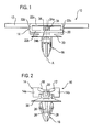
- Figur 1 eine Längsseitenansicht einer erfindungsgemäßen Befestigungsvorrichtung nach einer ersten Ausführungsform;
- Figur 2 eine Stirnseitenansicht der Befestigungsvorrichtung aus Figur 1;
- Figur 3 eine perspektivische Draufsicht auf die Befestigungsvorrichtung aus Figur 1;
- Figur 4 eine perspektivische Unteransicht der Befestigungsvorrichtung aus Figur 1;
- Figur 5 eine perspektivische Schnittansicht in der Ebene V in Figur 3;
- Figur 6 eine Längsseitenansicht einer erfindungsgemäßen Befestigungsvorrichtung nach einer zweiten Ausführungsform;
- Figur 7 eine Stirnseitenansicht der Befestigungsvorrichtung aus Figur 6;
- Figur 8 eine perspektivische Draufsicht auf die Befestigungsvorrichtung aus Figur 6;
- Figur 9 eine perspektivische Unteransicht der Befestigungsvorrichtung aus Figur 6; und
- Figur 10 eine perspektivische Schnittansicht in der Ebene X in Figur 8.
- In den Figuren ist eine Befestigungsvorrichtung 10 für eine Leitung (nicht gezeigt) mit einer länglichen, rinnenförmigen Schiene 12, einem Rahmen 14 und einem Befestigungsabschnitt 16 dargestellt. Die Schiene 12 ist zusammen mit dem Rahmen 14 einstückig ausgeführt. Auch der relativ zu Schiene 12 und Rahmen 14 bewegliche Befestigungsabschnitt 16 ist einstückig ausgeführt. Die gesamte Befestigungsvorrichtung 10 ist in einem Ein-Zyklus-Spritzgußverfahren aus demselben Kunststoff hergestellt, d.h. alle Bestandteile der Befestigungsvorrichtung 10 werden in einem einzigen Spritzvorgang bereits in ihrer Gebrauchsstellung gebildet und müssen nicht nachträglich zusammengebaut werden.
- Die rinnenförmige Schiene 12 weist auf ihrer Oberseite eine über ihre gesamte Länge durchgehende Auflagefläche 18 für die Leitung auf. Die Leitung kann z.B. mit einem Kabelbinder oder mit einer Kabelschelle an der Schiene 12 befestigt werden.
- Im mittleren Bereich der Schiene 12 ist auf deren Unterseite ein Führungsnocken 20 angeformt, der sich in Längsrichtung der Schiene 12 erstreckt. Im selben mittleren Bereich der Schiene 12 ist auf deren beiden Längsseiten ein Rahmenabschnitt 14a bzw. 14b mit vier Seitenwänden 22a, 22b, 22c, 22d angeformt. Die beiden Rahmenabschnitte 14a, 14b werden im folgenden als Rahmen 14 zusammengefaßt. Der Rahmen 14 begrenzt - gemäß der Darstellung der Figur 1 - einen horizontalen Freiheitsgrad (in Längsrichtung der Schiene 12) und einen vertikalen Freiheitsgrad des weiter unten genauer beschriebenen Befestigungsabschnitts 16. An den oberen und unteren Seitenwänden 22a, 22b des Rahmens 14 sind jeweils einander gegenüberliegende Vorsprünge 24a, 24b gebildet, die sich vom Führungsnocken 20 senkrecht nach außen erstrecken und eine Mittelposition bezüglich der Längserstreckung der Schiene 12 vorgeben.
- Der Befestigungsabschnitt 16 hat eine Mittelachse A und weist im unteren Bereich einen Mittelsteg 26 und zwei schräg nach oben gerichtete Arme 28 auf. Die elastisch nachgiebigen Arme 28 können hinter eine Trägeröffnung einer Fahrzeugkarosserie eingreifen und dadurch die Befestigungsvorrichtung 10 am Rand der Trägeröffnung arretieren. An den Mittelsteg 26 ist oberhalb der Arme 28 ein Federteller 30 angeformt, der bei der Montage gegen die Fahrzeugkarosserie gedrückt wird und aufgrund seiner Elastizität die Trägeröffnung abdichtet und zudem für eine Geräuschdämpfung sorgt.
- Oberhalb des Federtellers 30 weist der Befestigungsabschnitt 16 ein im Querschnitt U-förmiges Profil 32 auf, das dem Führungsnocken 20 gegenüberliegt. An der Oberseite des Profils 32 sind zwei Stegpaare 34 angeformt, die sich senkrecht zur Längsrichtung vom Profil 32 weg erstrecken und in den Rahmen 14 hineinragen. Auf diese Weise ist der Befestigungsabschnitt 16 unverlierbar, aber dennoch beweglich an der Schiene 12 gehalten.
- In der Normalposition des Befestigungsabschnitts 16 befinden sich die gegenüberliegenden Vorsprünge 24a, 24b zwischen den Stegpaaren 34. Abhängig vom Abstand der beiden Stege 34 jeden Paares ist dadurch eine geringe Beweglichkeit des Befestigungsabschnitts 16 in Längsrichtung der Schiene 12 gewährleistet. Da der vertikale Abstand zwischen den Vorsprüngen 24a, 24b nur geringfügig kleiner als die vertikale Abmessung der Stege 34 ist und sowohl die Vorsprünge 24a, 24b als auch die Stege 34 elastisch verformbar sind, kann der Befestigungsabschnitt 16 unter einem bestimmten Kraftaufwand in Längsrichtung der Schiene 12 aus seiner Normalposition herausbewegt werden. Der Führungsnocken 20 und das Profil 32 des Befestigungsabschnitts 16 unterstützen dabei die Längsführung des Befestigungsabschnitts 16.
- Die Beweglichkeit in Längsrichtung der Schiene 12 ist ebenso wie die Beweglichkeit in vertikaler Richtung (Axialrichtung des Befestigungsabschnitts 16) durch die Seitenwände 22a, 22b, 22c, 22d des Rahmens 14 begrenzt, die einen Anschlag für die Stege 34 bilden. Der Befestigungsabschnitt 16 kann auch quer zur Schiene 12 verschoben werden. Diese Beweglichkeit ist ebenfalls durch die Seitenwände 22a, 22b, 22c, 22d begrenzt, deren dem Führungsnocken 20 zugewandte Seiten einen Anschlag für die Außenwand des Profils 32 des Befestigungsabschnitts 16 bilden. Darüber hinaus ist ein Verkippen des Befestigungsabschnitts 16 relativ zur Schiene 12 in alle Richtungen möglich.
- Beim Anbringen der Befestigungsvorrichtung 10 an der Fahrzeugkarosserie befindet sich der Befestigungsabschnitt 16 in seiner Normalstellung. Falls erforderlich, kann die Schiene 12 vor allem in Längsrichtung, aber auch quer dazu verschoben und gegebenenfalls verkippt werden, so daß ein bestmöglicher Toleranzausgleich gewährleistet ist. Bei der bevorzugten Ausführungsform der erfindungsgemäßen Befestigungsvorrichtung 10 ist, ausgehend von der Normalposition, eine Längsverschiebung von bis zu 7 mm in beiden Richtungen möglich.
- In den Figuren 6 bis 10 ist eine zweite Ausführungsform der erfindungsgemäßen Befestigungsvorrichtung 10 gezeigt. Die zweite Ausführungsform ist der zuvor beschriebenen ersten Ausführungsform sehr ähnlich, so daß in den Figuren insoweit die gleichen Bezugszeichen verwendet werden. Im folgenden wird nur der wesentliche Unterschied zur ersten Ausführungsform beschrieben.
- Die Normalposition des Befestigungsabschnitts 16 ist hier nicht durch Vorsprünge am Rahmen 14 und Stegpaare des Befestigungsabschnitts 16 vorgegeben; vielmehr weisen die Rahmenabschnitte 14a und 14b vertikale Erweiterungen 36 auf, in denen Stege 38 des Befestigungsabschnitts 16 zu liegen kommen, die sich senkrecht zur Längsrichtung vom Profil 32 weg erstrecken und in den Rahmen 14 hineinragen.
Claims (11)
- Befestigungsvorrichtung für eine Leitung, mit einer länglichen Schiene (12) und einem Befestigungsabschnitt (16), der eine Axialrichtung definiert, wobei die Schiene (12) auf einer Oberseite eine Auflagefläche (18) für die Leitung aufweist und der Befestigungsabschnit (16) auf der der Oberseite entgegengesetzen Unterseite angeordnet ist, dadurch gekennzeichnet, daß der Befestigungsabschnitt (16) in einem Rahmen (14) verschiebbar gehalten ist.
- Befestigungsvorrichtung nach Anspruch 1, dadurch gekennzeichnet, daß der Rahmen (14) zusammen mit der Schiene (12) einstückig ausgeführt ist.
- Befestigungsvorrichtung nach Anspruch 1 oder 2, dadurch gekennzeichnet, daß die Auflagefläche (18) für die Leitung durchgehend ausgebildet ist.
- Befestigungsvorrichtung nach einem der vorhergehenden Ansprüche, dadurch gekennzeichnet, daß auf der Unterseite der Schiene (12) ein Führungsnocken (20) angeformt ist, der einem im Querschnitt U-förmigen Profil (32) des Befestigungsabschnitts (16) gegenüberliegt.
- Befestigungsvorrichtung nach einem der vorhergehenden Ansprüche, dadurch gekennzeichnet, daß der Befestigungsabschnitt (16) Stege (34; 38) aufweist, die sich senkrecht zur Längsrichtung der Schiene (12) erstrecken und in den Rahmen (14) hineinragen.
- Befestigungsvorrichtung nach Anspruch 5, dadurch gekennzeichnet, daß Seitenwände (22a, 22b, 22c, 22d) des Rahmens (14) wenigstens einen Anschlag für die Stege (34; 38) bilden.
- Befestigungsvorrichtung nach Anspruch 5 oder 6, dadurch gekennzeichnet, daß der Rahmen (14) so ausgebildet ist, daß er zusammenwirkend mit den Stegen (34; 38) eine stabile Normalposition für den Befestigungsabschnitt (16) vorgibt.
- Befestigungsvorrichtung nach Anspruch 7, dadurch gekennzeichnet, daß der Rahmen (14) einander gegenüberliegende Vorsprünge (24a, 24b) aufweist, die zusammen mit den Stegen (34) eine Rastposition des Befestigungsabschnitts (16) definieren.
- Befestigungsvorrichtung nach Anspruch 8, dadurch gekennzeichnet, daß der Abstand zwischen den Vorsprüngen (24a, 24b) geringfügig kleiner als die entsprechende Abmessung der Stege (34) ist.
- Befestigungsvorrichtung nach Anspruch 7, dadurch gekennzeichnet, daß der Rahmen (14) Erweiterungen (36) aufweist, in denen die Stege (38) zu liegen kommen.
- Befestigungsvorrichtung nach Anspruch 4 und einem der Ansprüche 6 bis 10, dadurch gekennzeichnet, daß die Seitenwände (22a, 22b, 22c, 22d) einen Anschlag für das Profil (32) des Befestigungsabschnitts (16) bilden.
Priority Applications (1)
| Application Number | Priority Date | Filing Date | Title |
|---|---|---|---|
| PL07012569T PL1873882T3 (pl) | 2006-06-29 | 2007-06-27 | Urządzenie mocujące dla przewodu |
Applications Claiming Priority (1)
| Application Number | Priority Date | Filing Date | Title |
|---|---|---|---|
| DE202006010110U DE202006010110U1 (de) | 2006-06-29 | 2006-06-29 | Befestigungsvorrichtung für eine Leitung |
Publications (2)
| Publication Number | Publication Date |
|---|---|
| EP1873882A1 true EP1873882A1 (de) | 2008-01-02 |
| EP1873882B1 EP1873882B1 (de) | 2010-08-04 |
Family
ID=37295874
Family Applications (1)
| Application Number | Title | Priority Date | Filing Date |
|---|---|---|---|
| EP07012569A Not-in-force EP1873882B1 (de) | 2006-06-29 | 2007-06-27 | Befestigungsvorrichtung für eine Leitung |
Country Status (5)
| Country | Link |
|---|---|
| EP (1) | EP1873882B1 (de) |
| AT (1) | ATE476774T1 (de) |
| DE (2) | DE202006010110U1 (de) |
| ES (1) | ES2349313T3 (de) |
| PL (1) | PL1873882T3 (de) |
Cited By (2)
| Publication number | Priority date | Publication date | Assignee | Title |
|---|---|---|---|---|
| EP2755290A4 (de) * | 2011-09-05 | 2017-03-15 | Sumitomo Wiring Systems, Ltd. | Aussenkörper eines kabelbaums |
| DE102018128682A1 (de) | 2018-11-15 | 2020-05-20 | Illinois Tool Works Inc. | Vorrichtung zur Befestigung einer Leitung an einem Trägerbauteil |
Families Citing this family (4)
| Publication number | Priority date | Publication date | Assignee | Title |
|---|---|---|---|---|
| DE202005007476U1 (de) * | 2005-05-11 | 2005-08-11 | Trw Automotive Electronics & Components Gmbh & Co. Kg | Befestigungsvorrichtung für ein Kabel |
| EP2404785B9 (de) * | 2010-07-02 | 2014-04-16 | SMR Patents S.à.r.l. | Befestigungselement für langgestrecktes Gut |
| CN103161573B (zh) * | 2013-03-15 | 2015-04-08 | 奇瑞汽车股份有限公司 | 一种线束卡子及发动机线束 |
| DE102014201972B4 (de) | 2014-02-04 | 2021-09-23 | Schlemmer Gmbh | Halteclip |
Citations (6)
| Publication number | Priority date | Publication date | Assignee | Title |
|---|---|---|---|---|
| EP0145238A2 (de) | 1983-11-21 | 1985-06-19 | Illinois Tool Works Inc. | Seitlich verstellbare Befestigungsvorrichtung |
| DE3933305A1 (de) | 1989-10-05 | 1991-04-18 | United Carr Gmbh Trw | Halteelement aus kunststoff |
| DE19539496A1 (de) * | 1995-10-24 | 1997-04-30 | Bayerische Motoren Werke Ag | Halteeinrichtung für langgestreckte Gegenstände, wie Kabel, Rohre oder dergleichen, insbesondere in einem Kraftfahrzeug |
| EP1286094A1 (de) * | 2001-07-13 | 2003-02-26 | I.T.W. Espana, S.A. | Verstellbare Stütze zur Befestigung von Kabelbündeln und dergleichen |
| EP1424520A1 (de) | 2002-11-29 | 2004-06-02 | Newfrey LLC | Befestigungsvorrichtung für einen länglichen Gegenstand, insbesondere Kabelbaum |
| DE202005007476U1 (de) | 2005-05-11 | 2005-08-11 | Trw Automotive Electronics & Components Gmbh & Co. Kg | Befestigungsvorrichtung für ein Kabel |
-
2006
- 2006-06-29 DE DE202006010110U patent/DE202006010110U1/de not_active Expired - Lifetime
-
2007
- 2007-06-27 PL PL07012569T patent/PL1873882T3/pl unknown
- 2007-06-27 DE DE502007004622T patent/DE502007004622D1/de active Active
- 2007-06-27 ES ES07012569T patent/ES2349313T3/es active Active
- 2007-06-27 AT AT07012569T patent/ATE476774T1/de active
- 2007-06-27 EP EP07012569A patent/EP1873882B1/de not_active Not-in-force
Patent Citations (6)
| Publication number | Priority date | Publication date | Assignee | Title |
|---|---|---|---|---|
| EP0145238A2 (de) | 1983-11-21 | 1985-06-19 | Illinois Tool Works Inc. | Seitlich verstellbare Befestigungsvorrichtung |
| DE3933305A1 (de) | 1989-10-05 | 1991-04-18 | United Carr Gmbh Trw | Halteelement aus kunststoff |
| DE19539496A1 (de) * | 1995-10-24 | 1997-04-30 | Bayerische Motoren Werke Ag | Halteeinrichtung für langgestreckte Gegenstände, wie Kabel, Rohre oder dergleichen, insbesondere in einem Kraftfahrzeug |
| EP1286094A1 (de) * | 2001-07-13 | 2003-02-26 | I.T.W. Espana, S.A. | Verstellbare Stütze zur Befestigung von Kabelbündeln und dergleichen |
| EP1424520A1 (de) | 2002-11-29 | 2004-06-02 | Newfrey LLC | Befestigungsvorrichtung für einen länglichen Gegenstand, insbesondere Kabelbaum |
| DE202005007476U1 (de) | 2005-05-11 | 2005-08-11 | Trw Automotive Electronics & Components Gmbh & Co. Kg | Befestigungsvorrichtung für ein Kabel |
Cited By (3)
| Publication number | Priority date | Publication date | Assignee | Title |
|---|---|---|---|---|
| EP2755290A4 (de) * | 2011-09-05 | 2017-03-15 | Sumitomo Wiring Systems, Ltd. | Aussenkörper eines kabelbaums |
| DE102018128682A1 (de) | 2018-11-15 | 2020-05-20 | Illinois Tool Works Inc. | Vorrichtung zur Befestigung einer Leitung an einem Trägerbauteil |
| WO2020102063A1 (en) | 2018-11-15 | 2020-05-22 | Illinois Tool Works Inc. | Device for fastening a line on a carrier component |
Also Published As
| Publication number | Publication date |
|---|---|
| EP1873882B1 (de) | 2010-08-04 |
| PL1873882T3 (pl) | 2011-01-31 |
| ATE476774T1 (de) | 2010-08-15 |
| ES2349313T3 (es) | 2010-12-29 |
| DE202006010110U1 (de) | 2006-10-12 |
| DE502007004622D1 (de) | 2010-09-16 |
Similar Documents
| Publication | Publication Date | Title |
|---|---|---|
| EP2259954B1 (de) | Wischblatt | |
| DE102009024983B4 (de) | Verbindungsbaugruppe | |
| EP0624133B1 (de) | Wischblatt zum überstreichen von scheiben an kraftfahrzeugen | |
| DE102006017878A1 (de) | Befestigungsclip | |
| EP1729386A2 (de) | Befestigungsvorrichtung für eine Leitung | |
| DE202008007783U1 (de) | In einem Loch befestigbares Halteelement | |
| EP1873882B1 (de) | Befestigungsvorrichtung für eine Leitung | |
| DE102005020011A1 (de) | Clip und Befestigungssystem mit einem Clip | |
| EP4350155B1 (de) | Befestigungsklammer, befestigungssystem und dachanordnung | |
| DE10043427B4 (de) | Wischvorrichtung | |
| DE19730600A1 (de) | Stulpschienenbeschlag | |
| DE102016103169B4 (de) | Adapter zur Fixierung eines Bodens an einer Seitenzarge, Schubkasten und Verfahren zur Montage eines Bodens an einem Adapter | |
| EP1780425A1 (de) | Verbindungselement | |
| DE202017007523U1 (de) | Möbel mit einem an einem Laufprofil verfahrbaren Schiebeelement und einer Führungseinrichtung | |
| DE102005012018B4 (de) | Anschlag zur Begrenzung des Stellweges einer Längsverstellvorrichtung für Sitze | |
| EP1844241B1 (de) | Vorrichtung zum ausgleich von toleranzen beim befestigen eines anbaukörpers an einem grundkörper | |
| EP1288123B1 (de) | Verkleidungselement für den Innenraum eines Fahrzeuges, insbesondere eines Luftfahrzeuges | |
| EP2651709A1 (de) | Wischblattvorrichtung | |
| DE10340196B4 (de) | Schlossmoduleinrichtung für eine Kraftfahrzeugtür | |
| DE4118662C2 (de) | Gleitelement für verschiebbare Teile, vorzugsweise Fahrzeugteile | |
| EP3967890A1 (de) | Verbindungselement für ein möbelstück, stecksystem mit einem solchen verbindungselement und ein verfahren zur montage eines möbelstücks | |
| DE20109717U1 (de) | Kopfstützenhülse für eine Führungsstange einer Kopfstütze | |
| DE102020006805A1 (de) | Verbinder zum Verbinden eines Schraubenkopfes oder einer Mutter mit einem Leitungshalter, System und Leiterrahmen eines Lastkraftwagens | |
| EP3675300A1 (de) | Adapter zur positionierung und befestigung eines installationsgehäuses | |
| EP2090789B1 (de) | Verbinder für rinnenförmige Profilstäbe und Verbindungsanordnung |
Legal Events
| Date | Code | Title | Description |
|---|---|---|---|
| PUAI | Public reference made under article 153(3) epc to a published international application that has entered the european phase |
Free format text: ORIGINAL CODE: 0009012 |
|
| AK | Designated contracting states |
Kind code of ref document: A1 Designated state(s): AT BE BG CH CY CZ DE DK EE ES FI FR GB GR HU IE IS IT LI LT LU LV MC MT NL PL PT RO SE SI SK TR |
|
| AX | Request for extension of the european patent |
Extension state: AL BA HR MK YU |
|
| RAP1 | Party data changed (applicant data changed or rights of an application transferred) |
Owner name: TRW AUTOMOTIVE ELECTRONICS & COMPONENTS GMBH |
|
| 17P | Request for examination filed |
Effective date: 20080605 |
|
| AKX | Designation fees paid |
Designated state(s): AT BE BG CH CY CZ DE DK EE ES FI FR GB GR HU IE IS IT LI LT LU LV MC MT NL PL PT RO SE SI SK TR |
|
| GRAP | Despatch of communication of intention to grant a patent |
Free format text: ORIGINAL CODE: EPIDOSNIGR1 |
|
| GRAS | Grant fee paid |
Free format text: ORIGINAL CODE: EPIDOSNIGR3 |
|
| GRAA | (expected) grant |
Free format text: ORIGINAL CODE: 0009210 |
|
| AK | Designated contracting states |
Kind code of ref document: B1 Designated state(s): AT BE BG CH CY CZ DE DK EE ES FI FR GB GR HU IE IS IT LI LT LU LV MC MT NL PL PT RO SE SI SK TR |
|
| REG | Reference to a national code |
Ref country code: GB Ref legal event code: FG4D Free format text: NOT ENGLISH |
|
| REG | Reference to a national code |
Ref country code: CH Ref legal event code: EP |
|
| REG | Reference to a national code |
Ref country code: IE Ref legal event code: FG4D Free format text: LANGUAGE OF EP DOCUMENT: GERMAN |
|
| REF | Corresponds to: |
Ref document number: 502007004622 Country of ref document: DE Date of ref document: 20100916 Kind code of ref document: P |
|
| REG | Reference to a national code |
Ref country code: SE Ref legal event code: TRGR |
|
| REG | Reference to a national code |
Ref country code: NL Ref legal event code: VDEP Effective date: 20100804 |
|
| REG | Reference to a national code |
Ref country code: HU Ref legal event code: AG4A Ref document number: E008703 Country of ref document: HU |
|
| REG | Reference to a national code |
Ref country code: ES Ref legal event code: FG2A Effective date: 20101216 |
|
| LTIE | Lt: invalidation of european patent or patent extension |
Effective date: 20100804 |
|
| PG25 | Lapsed in a contracting state [announced via postgrant information from national office to epo] |
Ref country code: FI Free format text: LAPSE BECAUSE OF FAILURE TO SUBMIT A TRANSLATION OF THE DESCRIPTION OR TO PAY THE FEE WITHIN THE PRESCRIBED TIME-LIMIT Effective date: 20100804 Ref country code: NL Free format text: LAPSE BECAUSE OF FAILURE TO SUBMIT A TRANSLATION OF THE DESCRIPTION OR TO PAY THE FEE WITHIN THE PRESCRIBED TIME-LIMIT Effective date: 20100804 Ref country code: LT Free format text: LAPSE BECAUSE OF FAILURE TO SUBMIT A TRANSLATION OF THE DESCRIPTION OR TO PAY THE FEE WITHIN THE PRESCRIBED TIME-LIMIT Effective date: 20100804 |
|
| REG | Reference to a national code |
Ref country code: PL Ref legal event code: T3 |
|
| PG25 | Lapsed in a contracting state [announced via postgrant information from national office to epo] |
Ref country code: SI Free format text: LAPSE BECAUSE OF FAILURE TO SUBMIT A TRANSLATION OF THE DESCRIPTION OR TO PAY THE FEE WITHIN THE PRESCRIBED TIME-LIMIT Effective date: 20100804 Ref country code: PT Free format text: LAPSE BECAUSE OF FAILURE TO SUBMIT A TRANSLATION OF THE DESCRIPTION OR TO PAY THE FEE WITHIN THE PRESCRIBED TIME-LIMIT Effective date: 20101206 Ref country code: BG Free format text: LAPSE BECAUSE OF FAILURE TO SUBMIT A TRANSLATION OF THE DESCRIPTION OR TO PAY THE FEE WITHIN THE PRESCRIBED TIME-LIMIT Effective date: 20101104 Ref country code: IS Free format text: LAPSE BECAUSE OF FAILURE TO SUBMIT A TRANSLATION OF THE DESCRIPTION OR TO PAY THE FEE WITHIN THE PRESCRIBED TIME-LIMIT Effective date: 20101204 Ref country code: CY Free format text: LAPSE BECAUSE OF FAILURE TO SUBMIT A TRANSLATION OF THE DESCRIPTION OR TO PAY THE FEE WITHIN THE PRESCRIBED TIME-LIMIT Effective date: 20100804 |
|
| REG | Reference to a national code |
Ref country code: IE Ref legal event code: FD4D |
|
| PG25 | Lapsed in a contracting state [announced via postgrant information from national office to epo] |
Ref country code: LV Free format text: LAPSE BECAUSE OF FAILURE TO SUBMIT A TRANSLATION OF THE DESCRIPTION OR TO PAY THE FEE WITHIN THE PRESCRIBED TIME-LIMIT Effective date: 20100804 Ref country code: GR Free format text: LAPSE BECAUSE OF FAILURE TO SUBMIT A TRANSLATION OF THE DESCRIPTION OR TO PAY THE FEE WITHIN THE PRESCRIBED TIME-LIMIT Effective date: 20101105 |
|
| PG25 | Lapsed in a contracting state [announced via postgrant information from national office to epo] |
Ref country code: IE Free format text: LAPSE BECAUSE OF FAILURE TO SUBMIT A TRANSLATION OF THE DESCRIPTION OR TO PAY THE FEE WITHIN THE PRESCRIBED TIME-LIMIT Effective date: 20100804 Ref country code: DK Free format text: LAPSE BECAUSE OF FAILURE TO SUBMIT A TRANSLATION OF THE DESCRIPTION OR TO PAY THE FEE WITHIN THE PRESCRIBED TIME-LIMIT Effective date: 20100804 |
|
| PG25 | Lapsed in a contracting state [announced via postgrant information from national office to epo] |
Ref country code: RO Free format text: LAPSE BECAUSE OF FAILURE TO SUBMIT A TRANSLATION OF THE DESCRIPTION OR TO PAY THE FEE WITHIN THE PRESCRIBED TIME-LIMIT Effective date: 20100804 Ref country code: SK Free format text: LAPSE BECAUSE OF FAILURE TO SUBMIT A TRANSLATION OF THE DESCRIPTION OR TO PAY THE FEE WITHIN THE PRESCRIBED TIME-LIMIT Effective date: 20100804 Ref country code: EE Free format text: LAPSE BECAUSE OF FAILURE TO SUBMIT A TRANSLATION OF THE DESCRIPTION OR TO PAY THE FEE WITHIN THE PRESCRIBED TIME-LIMIT Effective date: 20100804 |
|
| PLBE | No opposition filed within time limit |
Free format text: ORIGINAL CODE: 0009261 |
|
| STAA | Information on the status of an ep patent application or granted ep patent |
Free format text: STATUS: NO OPPOSITION FILED WITHIN TIME LIMIT |
|
| 26N | No opposition filed |
Effective date: 20110506 |
|
| PGFP | Annual fee paid to national office [announced via postgrant information from national office to epo] |
Ref country code: CZ Payment date: 20110620 Year of fee payment: 5 Ref country code: SE Payment date: 20110629 Year of fee payment: 5 |
|
| PGFP | Annual fee paid to national office [announced via postgrant information from national office to epo] |
Ref country code: PL Payment date: 20110602 Year of fee payment: 5 Ref country code: HU Payment date: 20110609 Year of fee payment: 5 |
|
| REG | Reference to a national code |
Ref country code: DE Ref legal event code: R097 Ref document number: 502007004622 Country of ref document: DE Effective date: 20110506 |
|
| PG25 | Lapsed in a contracting state [announced via postgrant information from national office to epo] |
Ref country code: MT Free format text: LAPSE BECAUSE OF FAILURE TO SUBMIT A TRANSLATION OF THE DESCRIPTION OR TO PAY THE FEE WITHIN THE PRESCRIBED TIME-LIMIT Effective date: 20100804 |
|
| BERE | Be: lapsed |
Owner name: TRW AUTOMOTIVE ELECTRONICS & COMPONENTS G.M.B.H. Effective date: 20110630 |
|
| REG | Reference to a national code |
Ref country code: CH Ref legal event code: PL |
|
| PG25 | Lapsed in a contracting state [announced via postgrant information from national office to epo] |
Ref country code: BE Free format text: LAPSE BECAUSE OF NON-PAYMENT OF DUE FEES Effective date: 20110630 |
|
| PG25 | Lapsed in a contracting state [announced via postgrant information from national office to epo] |
Ref country code: CH Free format text: LAPSE BECAUSE OF NON-PAYMENT OF DUE FEES Effective date: 20110630 Ref country code: LI Free format text: LAPSE BECAUSE OF NON-PAYMENT OF DUE FEES Effective date: 20110630 |
|
| REG | Reference to a national code |
Ref country code: SE Ref legal event code: EUG |
|
| PG25 | Lapsed in a contracting state [announced via postgrant information from national office to epo] |
Ref country code: CZ Free format text: LAPSE BECAUSE OF NON-PAYMENT OF DUE FEES Effective date: 20120627 |
|
| PG25 | Lapsed in a contracting state [announced via postgrant information from national office to epo] |
Ref country code: SE Free format text: LAPSE BECAUSE OF NON-PAYMENT OF DUE FEES Effective date: 20120628 |
|
| PG25 | Lapsed in a contracting state [announced via postgrant information from national office to epo] |
Ref country code: HU Free format text: LAPSE BECAUSE OF NON-PAYMENT OF DUE FEES Effective date: 20120628 Ref country code: MC Free format text: LAPSE BECAUSE OF NON-PAYMENT OF DUE FEES Effective date: 20110630 |
|
| PG25 | Lapsed in a contracting state [announced via postgrant information from national office to epo] |
Ref country code: LU Free format text: LAPSE BECAUSE OF NON-PAYMENT OF DUE FEES Effective date: 20110627 |
|
| REG | Reference to a national code |
Ref country code: AT Ref legal event code: MM01 Ref document number: 476774 Country of ref document: AT Kind code of ref document: T Effective date: 20120627 |
|
| PG25 | Lapsed in a contracting state [announced via postgrant information from national office to epo] |
Ref country code: PL Free format text: LAPSE BECAUSE OF NON-PAYMENT OF DUE FEES Effective date: 20120627 |
|
| PG25 | Lapsed in a contracting state [announced via postgrant information from national office to epo] |
Ref country code: TR Free format text: LAPSE BECAUSE OF FAILURE TO SUBMIT A TRANSLATION OF THE DESCRIPTION OR TO PAY THE FEE WITHIN THE PRESCRIBED TIME-LIMIT Effective date: 20100804 |
|
| REG | Reference to a national code |
Ref country code: PL Ref legal event code: LAPE |
|
| PG25 | Lapsed in a contracting state [announced via postgrant information from national office to epo] |
Ref country code: AT Free format text: LAPSE BECAUSE OF NON-PAYMENT OF DUE FEES Effective date: 20120627 |
|
| REG | Reference to a national code |
Ref country code: FR Ref legal event code: PLFP Year of fee payment: 9 |
|
| REG | Reference to a national code |
Ref country code: FR Ref legal event code: PLFP Year of fee payment: 10 |
|
| REG | Reference to a national code |
Ref country code: GB Ref legal event code: 732E Free format text: REGISTERED BETWEEN 20160915 AND 20160921 |
|
| REG | Reference to a national code |
Ref country code: DE Ref legal event code: R082 Ref document number: 502007004622 Country of ref document: DE Representative=s name: MEISSNER BOLTE PATENTANWAELTE RECHTSANWAELTE P, DE Ref country code: DE Ref legal event code: R082 Ref document number: 502007004622 Country of ref document: DE Representative=s name: HAUCK PATENTANWALTSPARTNERSCHAFT MBB, DE |
|
| REG | Reference to a national code |
Ref country code: FR Ref legal event code: PLFP Year of fee payment: 11 |
|
| REG | Reference to a national code |
Ref country code: DE Ref legal event code: R082 Ref document number: 502007004622 Country of ref document: DE Representative=s name: MEISSNER BOLTE PATENTANWAELTE RECHTSANWAELTE P, DE Ref country code: DE Ref legal event code: R082 Ref document number: 502007004622 Country of ref document: DE Representative=s name: HAUCK PATENTANWALTSPARTNERSCHAFT MBB, DE Ref country code: DE Ref legal event code: R081 Ref document number: 502007004622 Country of ref document: DE Owner name: ILLINOIS TOOL WORKS INC. (N.D.GES.D. STAATES D, US Free format text: FORMER OWNER: TRW AUTOMOTIVE ELECTRONICS & COMPONENTS GMBH, 78315 RADOLFZELL, DE |
|
| PGFP | Annual fee paid to national office [announced via postgrant information from national office to epo] |
Ref country code: FR Payment date: 20170627 Year of fee payment: 11 Ref country code: GB Payment date: 20170627 Year of fee payment: 11 |
|
| PGFP | Annual fee paid to national office [announced via postgrant information from national office to epo] |
Ref country code: IT Payment date: 20170622 Year of fee payment: 11 |
|
| REG | Reference to a national code |
Ref country code: GB Ref legal event code: 732E Free format text: REGISTERED BETWEEN 20170810 AND 20170816 |
|
| REG | Reference to a national code |
Ref country code: FR Ref legal event code: TP Owner name: ITW FASTENER PRODUCTS GMBH, DE Effective date: 20171002 |
|
| PGFP | Annual fee paid to national office [announced via postgrant information from national office to epo] |
Ref country code: DE Payment date: 20180627 Year of fee payment: 12 |
|
| GBPC | Gb: european patent ceased through non-payment of renewal fee |
Effective date: 20180627 |
|
| REG | Reference to a national code |
Ref country code: DE Ref legal event code: R082 Ref document number: 502007004622 Country of ref document: DE Representative=s name: MEISSNER BOLTE PATENTANWAELTE RECHTSANWAELTE P, DE |
|
| PG25 | Lapsed in a contracting state [announced via postgrant information from national office to epo] |
Ref country code: FR Free format text: LAPSE BECAUSE OF NON-PAYMENT OF DUE FEES Effective date: 20180630 Ref country code: IT Free format text: LAPSE BECAUSE OF NON-PAYMENT OF DUE FEES Effective date: 20180627 Ref country code: GB Free format text: LAPSE BECAUSE OF NON-PAYMENT OF DUE FEES Effective date: 20180627 |
|
| REG | Reference to a national code |
Ref country code: ES Ref legal event code: FD2A Effective date: 20190916 |
|
| PG25 | Lapsed in a contracting state [announced via postgrant information from national office to epo] |
Ref country code: ES Free format text: LAPSE BECAUSE OF NON-PAYMENT OF DUE FEES Effective date: 20180628 |
|
| REG | Reference to a national code |
Ref country code: DE Ref legal event code: R119 Ref document number: 502007004622 Country of ref document: DE |
|
| PG25 | Lapsed in a contracting state [announced via postgrant information from national office to epo] |
Ref country code: DE Free format text: LAPSE BECAUSE OF NON-PAYMENT OF DUE FEES Effective date: 20200101 |