EP1873384A2 - Engine front structure - Google Patents
Engine front structure Download PDFInfo
- Publication number
- EP1873384A2 EP1873384A2 EP07111239A EP07111239A EP1873384A2 EP 1873384 A2 EP1873384 A2 EP 1873384A2 EP 07111239 A EP07111239 A EP 07111239A EP 07111239 A EP07111239 A EP 07111239A EP 1873384 A2 EP1873384 A2 EP 1873384A2
- Authority
- EP
- European Patent Office
- Prior art keywords
- engine
- mounting
- camshaft
- cylinder head
- cover
- Prior art date
- Legal status (The legal status is an assumption and is not a legal conclusion. Google has not performed a legal analysis and makes no representation as to the accuracy of the status listed.)
- Withdrawn
Links
Images







Classifications
-
- F—MECHANICAL ENGINEERING; LIGHTING; HEATING; WEAPONS; BLASTING
- F02—COMBUSTION ENGINES; HOT-GAS OR COMBUSTION-PRODUCT ENGINE PLANTS
- F02F—CYLINDERS, PISTONS OR CASINGS, FOR COMBUSTION ENGINES; ARRANGEMENTS OF SEALINGS IN COMBUSTION ENGINES
- F02F7/00—Casings, e.g. crankcases
- F02F7/0065—Shape of casings for other machine parts and purposes, e.g. utilisation purposes, safety
- F02F7/0073—Adaptations for fitting the engine, e.g. front-plates or bell-housings
-
- B—PERFORMING OPERATIONS; TRANSPORTING
- B60—VEHICLES IN GENERAL
- B60K—ARRANGEMENT OR MOUNTING OF PROPULSION UNITS OR OF TRANSMISSIONS IN VEHICLES; ARRANGEMENT OR MOUNTING OF PLURAL DIVERSE PRIME-MOVERS IN VEHICLES; AUXILIARY DRIVES FOR VEHICLES; INSTRUMENTATION OR DASHBOARDS FOR VEHICLES; ARRANGEMENTS IN CONNECTION WITH COOLING, AIR INTAKE, GAS EXHAUST OR FUEL SUPPLY OF PROPULSION UNITS IN VEHICLES
- B60K5/00—Arrangement or mounting of internal-combustion or jet-propulsion units
- B60K5/12—Arrangement of engine supports
- B60K5/1208—Resilient supports
- B60K5/1216—Resilient supports characterised by the location of the supports relative to the motor or to each other
Definitions
- the present invention relates to an engine front structure, and more particularly to an engine front structure equipped with a variable camshaft timing mechanism at a front end of a camshaft of the engine, which is designed to reduce an engine overall length while providing enhanced mounting and supporting stiffness.
- an engine for a vehicle such as a transverse engine designed to be mounted on a vehicle body in such a manner that a crankshaft of said engine is oriented in a width direction (i.e., lateral direction) of the vehicle body
- one of the key challenges is how to reduce an outside dimension of the engine in an axial direction of the crankshaft, i.e., an overall engine length.
- a key task is focused on a fixing structure of an engine mounting bracket for mounting and supporting an engine (including a powertrain unit which is an integrally assembled engine with a transmission unit) relative to a vehicle body, particularly a fixing structure of a mounting bracket for mounting and supporting a front of an engine body relative to a vehicle body.
- variable camshaft timing mechanism also known as “variable cam phase mechanism”
- a solenoid-controlled type variable camshaft timing mechanism at a front end of a camshaft of the engine to controllably change a rotational phase of the camshaft so as to change valve timings
- the variable camshaft timing mechanism becomes a negative factor causing an increase in overall engine length.
- it becomes critical to achieve a shorter overall engine length based on an improvement of an engine front structure including an engine mounting bracket fixing structure.
- the above techniques have heretofore been known.
- the technique of arranging an engine mounting bracket in a cutout partially formed in a timing cover involves a problem about structural complexity, such as a complicated configuration required for allowing the engine mounting bracket to be used as a part of the timing cover and fixed to an engine body.
- structural complexity such as a complicated configuration required for allowing the engine mounting bracket to be used as a part of the timing cover and fixed to an engine body.
- an object of the present invention to provide an engine front structure equipped with a variable camshaft timing mechanism at a front end of a camshaft of the engine, which is capable of reducing an overall engine length while providing enhanced mounting and supporting stiffness.
- the present invention provides an engine front structure in which an engine includes an engine body having a cylinder block and a cylinder head disposed at a top of the cylinder bock; intake and exhaust camshafts which are disposed in an upper portion of the cylinder head and in parallel relation to each other; and a variable camshaft timing mechanism provided at one end of at least the intake camshaft in the camshafts to controllably change a rotational phase of corresponding camshaft.
- the variable camshaft timing mechanism is located on the side of a front of the engine where a camshaft driving force transmission mechanism is arranged.
- the engine is also provided with a timing cover.
- the engine front structure is provided with: a cover body of the timing cover which covers the camshaft driving force transmission mechanism at a position opposed to a front surface of the cylinder head; an upper extension portion of the timing cover which extends upwardly from an upper portion of the cover body and has an inner surface formed with a depression receiving therein the variable camshaft timing mechanism; a fastening seat on the cover body with a relatively high stiffness which is located beneath of the upper extension portion and centrally in a width direction of the engine and is fastened to the engine body; an engine-mounting-bracket receiving seat which is formed on a top surface of the upper extension portion to have a relatively high stiffness and attached to an engine mounting bracket; and a connection portion which is provided on a central region of the inner surface of the upper extension portion in the width direction of the engine to extend along the depression and connect between the fastening seat and the engine-mounting-bracket receiving seat with a relatively high stiffness.
- variable camshaft timing mechanism can be received in the depression formed in the inner surface of the upper extension portion of the timing cover, without hindering desirable reduction in overall engine length.
- the engine mounting bracket can be formed to extend above the timing cover so as to be fixed to the engine-mounting-bracket receiving seat formed on the top surface of the upper extension portion of the timing cover.
- the upper extension portion of the timing cover has the high-stiffness connection portion formed on a central region of the inner surface of the upper extension portion in the width direction of the engine to extend along the depression receiving therein the variable camshaft timing mechanism and connect between the high-stiffness fastening seat and the engine-mounting-bracket receiving seat.
- FIGS. 1 to 12 show an engine front structure, according to an embodiment of the present invention.
- the engine is an inline four-cylinder transverse engine designed to be mounted on a vehicle body in such a manner that a crankshaft 3a thereof is oriented in a width direction (i.e., lateral direction) of the vehicle body.
- the engine is mounted in an engine compartment of a front of the vehicle body in a three-point mounting manner in such a way that a front end thereof is supported relative to a front frame 1 of the vehicle body by an engine mount 2 and a rear end thereof is supported by two mount portions (not shown) arranged in a longitudinal direction of the vehicle body.
- the engine is provided with an engine body B which has a cylinder block 3 and a cylinder head 4 disposed at a top of the cylinder bock 3.
- An intake camshaft 5 and an exhaust camshaft 6 are disposed in an upper portion of the cylinder head 4 and in parallel relation to each other.
- a camshaft driving force transmission mechanism (not shown) is arranged on the side of a front surface of the engine body B (corresponding to one longitudinal end of the crankshaft 3a) to transmit a driving force from the crankshaft 3a to each of the camshafts 5 and 6.
- Two solenoid-controlled type variable camshaft timing mechanisms 7 and 8 each incorporating a solenoid actuator are disposed at and associated with respective front ends of the intake and exhaust camshafts 5 and 6.
- Each of the variable camshaft timing mechanisms 7 and 8 has a conventional structure as disclosed in, for example, U.S. Patent Application Publication No. 20050132988 .
- a timing cover 9 is disposed in opposed relation to a front surface of the cylinder head 4 to cover the camshaft driving force transmission mechanism, and a casing cover 10 is disposed in opposed relation to a front surface of the cylinder block 3.
- the timing cover 9 and the casing cover 10 are fastened to the engine body B with a bolt so as to be assembled together. It is understood that these covers 9 and 10 may be integrally formed as a single component.
- the timing cover 9 has a cover body 9a which is opposed to the front surface of the cylinder head 4, and an upper extension portion 9b which extends upwardly from an upper portion of the cover body 9a and reaches a height position along a front edge of a cylinder head cover 11 disposed above the cylinder head 4.
- the upper extension portion 9b has an inner surface, i.e., a surface on a rearward side of the engine, which is formed with two depressions 12 and 13 each formed to have an approximately circular shape and receive therein a corresponding one of the variable camshaft timing mechanisms 7 and 8 disposed at the respective front ends of the intake and exhaust camshafts 5 and 6.
- the cover body 9a has a fastening seat 14 in an approximately central region thereof.
- the fastening seat 14 is increased in wall thickness to have a relatively high stiffness, and fastened to the engine body B (cylinder head 4) with a bolt.
- the upper extension portion 9b has an engine-mounting-bracket receiving seat 16 extending from a central region to a right (in front view) end of a top surface thereof.
- the engine-mounting-bracket receiving seat 16 is increased in wall thickness to have a relatively high stiffness, and formed to have a seat surface 16a allowing an engine mounting bracket 15 to be fastened thereto at two positions with bolts.
- the upper extension portion 9b also has a connection portion 17 formed on a central region of the inner surface thereof in a width direction of the engine.
- the connection portion 17 is increased in wall thickness to have a relatively high stiffness.
- the upper extension portion 9b is formed to extend along the depressions 12 and 13 and connect between the fastening seat 14 and the engine-mounting-bracket receiving seat 16.
- the timing cover 9 has two flanges 18 and 19 provided along respective side edges of the timing cover 9 which are opposed to each other in the width direction of the engine, and fastened to the cylinder head 4 with bolts.
- the flange 18 (on the right side in front view) is formed to have a wall thickness greater than that of the flange 19 (on the left side in front view), i.e., have a stiffness greater than that of the flange 19, and connect with the engine-mounting-bracket receiving seat 16 through the upper extension portion 9b.
- Each of the depressions 12 and 13 receiving therein the respective variable camshaft timing mechanisms 7 and 8 has two side walls 20 and 21 located in opposed relation to each other in the width direction of the engine. Each of the side walls 20 and 21 is increased in wall thickness to have a relatively high stiffness, and formed to connect with the engine-mounting-bracket receiving seat 16.
- the top surface of the upper extension portion 9b is formed with a sealing edge 22 on the rearward side of the engine relative to the engine-mounting-bracket receiving seat 16 of the upper extension portion 9b, to allow a front edge 11a of the cylinder head cover 11 to be attached thereto along the engine-mounting-bracket receiving seat 16.
- the seat surface 16a of the engine-mounting-bracket receiving seat 16 is formed substantially flat.
- the connection portion 17 continuously extends from the top of the fastening seat 14 and extends continuously to the engine-mounting-bracket receiving seat 16.
- the engine-mounting-bracket receiving seat 16 and the connection portion 17 share the common side surfaces that are right & left circular shaped inner side surfaces 12a, 13a of the right and left depressions 12, 13 which receive therein said variable camshaft mechanism 7, 8.
- a cross sectional area of the side surfaces 12a, 13a taken along a horizontal line is substantially a filled rectangle from the lowermost of the depressions 12, 13 to the topmost of the depressions 12, 13, except a fastening hole 16s.
- connection portion 17 and the stiffness of the engine-mounting-bracket receiving seat 16 are made much higher than those corresponding elements of the timing cover with the structure where only a circumferential rib (or ribs) with a certain thickness is formed to surround the variable camshaft timing mechanisms 7, 8.
- the mounting bracket 15 has an upper fastening surface portion 51 which is fastened to the seat surface 16a of the timing cover 9 with a bolt, a lower fastening surface portion 52 which is fastened to the engine mount 2 with a bolt, and a connection portion 53 extending upward from the lower fastening surface portion 52 to the upper fastening surface portion 51.
- the upper fastening surface portion 51 is formed with two bolt holes 54 and 55 for bolting
- the lower fastening surface portion 52 is formed with one bolt hole 56 having a diameter greater than that of each of the bolt holes 54 and 55.
- the engine includes a frontmost camshaft bearing portion 31 which supports the camshafts 5 and 6 at a frontmost position of the cylinder head 4.
- the frontmost camshaft bearing portion 31 is in the form of upper and lower bearing members 32 and 33 respectively separatable from the cylinder head 4.
- Each of the upper and lower bearing members 32 and 33 is designed to rotatably support respective halves of the front ends of the intake and exhaust camshafts 5 and 6.
- the cylinder head 4 is formed with two fastening portions (bolt bosses) 34 and 35 at respective positions downwardly overlapping the frontmost camshaft bearing portion 31 to fasten the cylinder head 4 to the cylinder block 3 with bolts therethrough.
- the codes S1 and S2 indicate a sealing rubber which seals between the timing cover 9 and the cylinder head cover 11, and a sealing rubber which seals between the cylinder head 4 and the cylinder head cover 11, respectively.
- These sealing rubbers S1 and S2 are integrally formed as a single component.
- the present invention may be applied to various types of engines, for example, an engine equipped with a hydraulically-controlled type variable camshaft timing mechanism for an exhaust camshaft.
- a first aspect of the present invention relates to an engine front structure where an engine includes an engine body having a cylinder block and a cylinder head disposed at a top of the cylinder bock; intake and exhaust camshafts which are disposed in an upper portion of the cylinder head and in parallel relation to each other; and a variable camshaft timing mechanism provided at one end of at least the intake camshaft in the camshafts to controllably change a rotational phase of corresponding camshaft.
- the variable camshaft timing mechanism is located on the side of a front of the engine where a camshaft driving force transmission mechanism is arranged.
- the engine is also provided with a timing cover.
- the engine front structure is provided with: a cover body of the timing cover which covers the camshaft driving force transmission mechanism at a position opposed to a front surface of the cylinder head; an upper extension portion of the timing cover which extends upwardly from an upper portion of the cover body and has an inner surface formed with a depression receiving therein the variable camshaft timing mechanism; a fastening seat on the cover body with a relatively high stiffness which is located beneath of the upper extension portion and centrally in a width direction of the engine and is fastened to the engine body; an engine-mounting-bracket receiving seat which is formed on a top surface of the upper extension portion to have a relatively high stiffness and attached to an engine mounting bracket; and a connection portion which is provided on a central region of the inner surface of the upper extension portion in the width direction of the engine to extend along the depression and connect between the fastening seat and the engine-mounting-bracket receiving seat with a relatively high stiffness.
- the timing cover has two flanges which are provided along respective side edges of the timing cover to be attached to the cylinder head and are integrally connected with the engine-mounting-bracket receiving seat through the upper extension portion.
- one of the flanges is formed to have a stiffness greater than that of the other flange.
- variable camshaft timing mechanism is a solenoid-controlled type variable camshaft timing mechanism incorporating a solenoid actuator
- the upper extension portion of the timing cover has an overlapping region with the variable camshaft timing mechanism.
- the overlapping region is formed to be concaved forwardly relative to the front of the engine so as to define the depression receiving therein the variable camshaft timing mechanism in such a manner that the depression has two side walls located in opposed relation to each other in the width direction of the engine and each formed to have a relatively high stiffness and connect with the engine-mounting-bracket receiving seat.
- the engine is a transverse engine designed to be mounted and supported relative to a front frame of a vehicle body in such a manner that a crankshaft of the engine is oriented in a lateral direction of the vehicle body.
- a frontmost camshaft bearing portion which supports the camshafts at a frontmost position of the cylinder head.
- the frontmost camshaft bearing portion is in the form of upper and lower bearing members respectively separatable from the cylinder head.
- a fastening portion is formed with the cylinder head at a position beneath of the frontmost camshaft bearing portion to fasten the cylinder head to the cylinder block with a bolt therethrough.
- a cylinder head cover disposed above the cylinder head, and the top surface of the upper extension portion is formed with a sealing edge on a rearward side of the engine relative to the engine-mounting-bracket receiving seat of the upper extension portion, to allow a front edge of the cylinder head cover to be attached thereto along the engine-mounting-bracket receiving seat.
- a second aspect of the present invention relates to an engine front structure where an engine includes an engine body having a cylinder block and a cylinder head disposed at a top of the cylinder bock; intake and exhaust camshafts which are disposed in an upper portion of the cylinder head and in parallel relation to each other; and a variable camshaft timing mechanism provided at one end of at least the intake camshaft in the camshafts to controllably change a rotational phase of corresponding camshaft.
- the variable camshaft timing mechanism is located on the side of a front of the engine where a camshaft driving force transmission mechanism is arranged.
- the engine is also provided with a timing cover.
- the engine front structure is provided with: a cover body of the timing cover which covers the camshaft driving force transmission mechanism at a position opposed to a front surface of the cylinder head; an upper extension portion of the timing cover which extends upwardly from an upper portion of the cover body and has an inner surface formed with a depression receiving therein the variable camshaft timing mechanism; a fastening seat on the cover body with a relatively high stiffness which is located beneath of the upper extension portion and centrally in a width direction of the engine and is fastened to the engine body; an engine-mounting-bracket receiving seat which is formed on a top surface of the upper extension portion to have a relatively high stiffness and attached to an engine mounting bracket; and a connection portion which is provided on a central region of the inner surface of the upper extension portion in the width direction of the engine to extend along the depression and connect between the fastening seat and the engine-mounting-bracket receiving seat with a relatively high stiffness.
- the timing cover has two flanges which are provided along respective side edges of the timing cover to be attached to the cylinder head and are integrally connected with the engine-mounting-bracket receiving seat through the upper extension portion.
- one of the flanges is formed to have a stiffness greater than that of the other flange.
- One of the flanges is formed to have a stiffness greater than that of the other flange, and connect with the engine-mounting-bracket receiving seat through the upper extension portion.
- the engine is a transverse engine designed to be mounted and supported relative to a front frame of a vehicle body in such a manner that a crankshaft of the engine is oriented in a lateral direction of the vehicle body.
- a third aspect of the present invention relates to an engine front structure where an engine includes an engine body having a cylinder block and a cylinder head disposed at a top of the cylinder bock; intake and exhaust camshafts which are disposed in an upper portion of the cylinder head and in parallel relation to each other; and a variable camshaft timing mechanism provided at one end of at least the intake camshaft in the camshafts to controllably change a rotational phase of corresponding camshaft.
- the variable camshaft timing mechanism is located on the side of a front of the engine where a camshaft driving force transmission mechanism is arranged.
- the engine is also provided with a timing cover.
- the engine front structure is provided with: a cover body of the timing cover which covers the camshaft driving force transmission mechanism at a position opposed to a front surface of the cylinder head; an upper extension portion of the timing cover which extends upwardly from an upper portion of the cover body and has an inner surface formed with a depression receiving therein the variable camshaft timing mechanism; a fastening seat on the cover body with a relatively high stiffness which is located beneath of the upper extension portion and centrally in a width direction of the engine and is fastened to the engine body; an engine-mounting-bracket receiving seat which is formed on a top surface of the upper extension portion to have a relatively high stiffness and attached to an engine mounting bracket; and a connection portion which is provided on a central region of the inner surface of the upper extension portion in the width direction of the engine to extend along the depression and connect between the fastening seat and the engine-mounting-bracket receiving seat with a relatively high stiffness.
- the variable camshaft timing mechanism is a solenoid-controlled type variable camshaft timing mechanism incorporating a solenoid actuator.
- the upper extension portion of the timing cover has an overlapping region with the variable camshaft timing mechanism.
- the overlapping region is formed to be concaved forwardly relative to the front of the engine so as to define the depression receiving therein the variable camshaft timing mechanism in such a manner that the depression has two side walls located in opposed relation to each other in the width direction of the engine and each formed to have a relatively high stiffness and connect with the engine-mounting-bracket seat.
- the engine is a transverse engine designed to be mounted and supported relative to a front frame of a vehicle body in such a manner that a crankshaft of the engine is oriented in a lateral direction of the vehicle body.
Landscapes
- Engineering & Computer Science (AREA)
- Chemical & Material Sciences (AREA)
- Combustion & Propulsion (AREA)
- Mechanical Engineering (AREA)
- General Engineering & Computer Science (AREA)
- Transportation (AREA)
- Cylinder Crankcases Of Internal Combustion Engines (AREA)
- Valve-Gear Or Valve Arrangements (AREA)
- Arrangement Or Mounting Of Propulsion Units For Vehicles (AREA)
- Valve Device For Special Equipments (AREA)
Abstract
Description
- The present invention relates to an engine front structure, and more particularly to an engine front structure equipped with a variable camshaft timing mechanism at a front end of a camshaft of the engine, which is designed to reduce an engine overall length while providing enhanced mounting and supporting stiffness.
- In an engine for a vehicle, such as a transverse engine designed to be mounted on a vehicle body in such a manner that a crankshaft of said engine is oriented in a width direction (i.e., lateral direction) of the vehicle body, one of the key challenges is how to reduce an outside dimension of the engine in an axial direction of the crankshaft, i.e., an overall engine length. Further, in a design process aiming to reduce the overall engine length, a key task is focused on a fixing structure of an engine mounting bracket for mounting and supporting an engine (including a powertrain unit which is an integrally assembled engine with a transmission unit) relative to a vehicle body, particularly a fixing structure of a mounting bracket for mounting and supporting a front of an engine body relative to a vehicle body. In particular, in an engine equipped with a variable camshaft timing mechanism (also known as "variable cam phase mechanism"), especially a solenoid-controlled type variable camshaft timing mechanism, at a front end of a camshaft of the engine to controllably change a rotational phase of the camshaft so as to change valve timings, the variable camshaft timing mechanism becomes a negative factor causing an increase in overall engine length. Thus, it becomes critical to achieve a shorter overall engine length based on an improvement of an engine front structure including an engine mounting bracket fixing structure.
- For example, as a technique of mounting an engine in an engine compartment of a vehicle in a transverse arrangement where a crankshaft of said engine is oriented in a lateral direction of a vehicle body, there has been known a structure for mounting and supporting a front end of an engine body, or one of transverse ends with respect to vehicle, where a camshaft driving force transmission mechanism is arranged, wherein a timing cover fixed to a cylinder head and a cylinder block with a bolt to cover a camshaft driving force transmission mechanism is partially formed with a cutout, and an engine mounting bracket is placed in the cutout and fixed to the cylinder head with a bolt, so that the engine mounting bracket serves additionally as a part of the timing cover in order to facilitate a reduction in overall engine length (see, for example,
U.S. Patent No. 5,743,229 ). - As to a structure for mounting and supporting a front end of an engine body in a transverse engine, the above techniques have heretofore been known. Among them, the technique of arranging an engine mounting bracket in a cutout partially formed in a timing cover involves a problem about structural complexity, such as a complicated configuration required for allowing the engine mounting bracket to be used as a part of the timing cover and fixed to an engine body. Moreover, it is not easy to firmly fix the engine mounting bracket onto a front end surface of the engine body which can afford only an extremely limited space therefor due to a camshaft driving force transmission mechanism complicatedly arranged thereover.
- In view of the above problems, it is an object of the present invention to provide an engine front structure equipped with a variable camshaft timing mechanism at a front end of a camshaft of the engine, which is capable of reducing an overall engine length while providing enhanced mounting and supporting stiffness.
- In order to achieve this object, the present invention provides an engine front structure in which an engine includes an engine body having a cylinder block and a cylinder head disposed at a top of the cylinder bock; intake and exhaust camshafts which are disposed in an upper portion of the cylinder head and in parallel relation to each other; and a variable camshaft timing mechanism provided at one end of at least the intake camshaft in the camshafts to controllably change a rotational phase of corresponding camshaft. The variable camshaft timing mechanism is located on the side of a front of the engine where a camshaft driving force transmission mechanism is arranged. The engine is also provided with a timing cover. The engine front structure is provided with: a cover body of the timing cover which covers the camshaft driving force transmission mechanism at a position opposed to a front surface of the cylinder head; an upper extension portion of the timing cover which extends upwardly from an upper portion of the cover body and has an inner surface formed with a depression receiving therein the variable camshaft timing mechanism; a fastening seat on the cover body with a relatively high stiffness which is located beneath of the upper extension portion and centrally in a width direction of the engine and is fastened to the engine body; an engine-mounting-bracket receiving seat which is formed on a top surface of the upper extension portion to have a relatively high stiffness and attached to an engine mounting bracket; and a connection portion which is provided on a central region of the inner surface of the upper extension portion in the width direction of the engine to extend along the depression and connect between the fastening seat and the engine-mounting-bracket receiving seat with a relatively high stiffness.
- In the engine front structure of the present invention, the variable camshaft timing mechanism can be received in the depression formed in the inner surface of the upper extension portion of the timing cover, without hindering desirable reduction in overall engine length. In addition, the engine mounting bracket can be formed to extend above the timing cover so as to be fixed to the engine-mounting-bracket receiving seat formed on the top surface of the upper extension portion of the timing cover. Thus, a front end of the engine body can be supported from above without using an engine-mounting-bracket support portion hindering desirable reduction in overall engine length, for example, to be provided on a front surface of the timing cover. Further, in addition to a high stiffness of the engine-mounting-bracket receiving seat itself, the upper extension portion of the timing cover has the high-stiffness connection portion formed on a central region of the inner surface of the upper extension portion in the width direction of the engine to extend along the depression receiving therein the variable camshaft timing mechanism and connect between the high-stiffness fastening seat and the engine-mounting-bracket receiving seat. This makes it possible to ensure a high mounting and supporting stiffness, and facilitate a reduction in overall engine length while providing enhanced mounting and supporting stiffness.
- These and other objects, features and advantages of the invention will become more apparent upon reading the following detailed description along with the accompanying drawings.
-
- FIG. 1 is a top plan view showing an engine front structure, according to an embodiment of the present invention, in a state after a front of the engine is mounted and supported relative to a vehicle body, wherein a cylinder head cover is detached from the engine;
- FIG. 2 is a side view showing the engine front structure according to the embodiment of the present invention, in the state after the front of the engine is mounted and supported relative to the vehicle body;
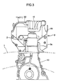
- FIG. 3 is a front view showing the engine front structure according to the embodiment of the present invention, in the state after the front of the engine is mounted and supported relative to the vehicle body;
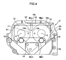
- FIG. 4 is a front view showing a timing cover in the engine front structure according to the embodiment of the present invention;
- FIG. 5 is a back view of the timing cover in FIG. 4;
- FIG. 6 is a top plan view of the timing cover in FIG. 4;
- FIG. 7 is a sectional view taken along the line VII-VII in FIG. 4;
- FIG. 8 is a sectional view taken along the line VIII-VIII in FIG. 4;
- FIG. 9 is a top plan view showing an engine mounting bracket in the engine front structure according to the embodiment of the present invention;
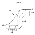
- FIG. 10 is a side view of the engine mounting bracket in FIG. 9;
- FIG. 11 is a top plan view showing a front of a cylinder head in the engine front structure according to the embodiment of the present invention; and
- FIG. 12 is a front view showing the cylinder head in FIG. 11.
- FIGS. 1 to 12 show an engine front structure, according to an embodiment of the present invention. In this embodiment, the engine is an inline four-cylinder transverse engine designed to be mounted on a vehicle body in such a manner that a
crankshaft 3a thereof is oriented in a width direction (i.e., lateral direction) of the vehicle body. Specifically, the engine is mounted in an engine compartment of a front of the vehicle body in a three-point mounting manner in such a way that a front end thereof is supported relative to afront frame 1 of the vehicle body by anengine mount 2 and a rear end thereof is supported by two mount portions (not shown) arranged in a longitudinal direction of the vehicle body. - Referring to FIG. 2, the engine is provided with an engine body B which has a cylinder block 3 and a
cylinder head 4 disposed at a top of the cylinder bock 3. Anintake camshaft 5 and an exhaust camshaft 6 (see FIG. 1) are disposed in an upper portion of thecylinder head 4 and in parallel relation to each other. - In a front of the engine, a camshaft driving force transmission mechanism (not shown) is arranged on the side of a front surface of the engine body B (corresponding to one longitudinal end of the
crankshaft 3a) to transmit a driving force from thecrankshaft 3a to each of thecamshafts - Two solenoid-controlled type variable
camshaft timing mechanisms exhaust camshafts camshaft timing mechanisms U.S. Patent Application Publication No. 20050132988 . - On the side of the front surface of the engine body B, a
timing cover 9 is disposed in opposed relation to a front surface of thecylinder head 4 to cover the camshaft driving force transmission mechanism, and acasing cover 10 is disposed in opposed relation to a front surface of the cylinder block 3. Thetiming cover 9 and thecasing cover 10 are fastened to the engine body B with a bolt so as to be assembled together. It is understood that thesecovers - Referring to FIG. 3, the
timing cover 9 has acover body 9a which is opposed to the front surface of thecylinder head 4, and anupper extension portion 9b which extends upwardly from an upper portion of thecover body 9a and reaches a height position along a front edge of acylinder head cover 11 disposed above thecylinder head 4. - As shown in FIGS. 4 and 5, the
upper extension portion 9b has an inner surface, i.e., a surface on a rearward side of the engine, which is formed with twodepressions camshaft timing mechanisms exhaust camshafts cover body 9a has afastening seat 14 in an approximately central region thereof. The fasteningseat 14 is increased in wall thickness to have a relatively high stiffness, and fastened to the engine body B (cylinder head 4) with a bolt. Theupper extension portion 9b has an engine-mounting-bracket receiving seat 16 extending from a central region to a right (in front view) end of a top surface thereof. The engine-mounting-bracket receiving seat 16 is increased in wall thickness to have a relatively high stiffness, and formed to have aseat surface 16a allowing anengine mounting bracket 15 to be fastened thereto at two positions with bolts. Theupper extension portion 9b also has aconnection portion 17 formed on a central region of the inner surface thereof in a width direction of the engine. Theconnection portion 17 is increased in wall thickness to have a relatively high stiffness. Theupper extension portion 9b is formed to extend along thedepressions fastening seat 14 and the engine-mounting-bracket receiving seat 16. - Referring to FIGS. 4 and 5, the
timing cover 9 has twoflanges timing cover 9 which are opposed to each other in the width direction of the engine, and fastened to thecylinder head 4 with bolts. The flange 18 (on the right side in front view) is formed to have a wall thickness greater than that of the flange 19 (on the left side in front view), i.e., have a stiffness greater than that of theflange 19, and connect with the engine-mounting-bracket receiving seat 16 through theupper extension portion 9b. Each of thedepressions camshaft timing mechanisms side walls side walls bracket receiving seat 16. - Referring to FIGS. 4 to 8, the top surface of the
upper extension portion 9b is formed with a sealingedge 22 on the rearward side of the engine relative to the engine-mounting-bracket receiving seat 16 of theupper extension portion 9b, to allow afront edge 11a of thecylinder head cover 11 to be attached thereto along the engine-mounting-bracket receiving seat 16. - As shown in Figs. 4 and 5, the
seat surface 16a of the engine-mounting-bracket receiving seat 16 is formed substantially flat. Theconnection portion 17 continuously extends from the top of thefastening seat 14 and extends continuously to the engine-mounting-bracket receiving seat 16. The engine-mounting-bracket receiving seat 16 and theconnection portion 17 share the common side surfaces that are right & left circular shapedinner side surfaces depressions variable camshaft mechanism depressions depressions fastening hole 16s. - With the above structure and the cross sectional area, the stiffness of the
connection portion 17 and the stiffness of the engine-mounting-bracket receiving seat 16 are made much higher than those corresponding elements of the timing cover with the structure where only a circumferential rib (or ribs) with a certain thickness is formed to surround the variablecamshaft timing mechanisms - Referring to FIGS. 9 and 10, the mounting
bracket 15 has an upperfastening surface portion 51 which is fastened to theseat surface 16a of thetiming cover 9 with a bolt, a lowerfastening surface portion 52 which is fastened to theengine mount 2 with a bolt, and aconnection portion 53 extending upward from the lowerfastening surface portion 52 to the upperfastening surface portion 51. The upperfastening surface portion 51 is formed with twobolt holes fastening surface portion 52 is formed with onebolt hole 56 having a diameter greater than that of each of the bolt holes 54 and 55. - Referring to FIGS. 11 and 12, the engine includes a frontmost
camshaft bearing portion 31 which supports thecamshafts cylinder head 4. The frontmostcamshaft bearing portion 31 is in the form of upper andlower bearing members cylinder head 4. Each of the upper andlower bearing members exhaust camshafts cylinder head 4 is formed with two fastening portions (bolt bosses) 34 and 35 at respective positions downwardly overlapping the frontmostcamshaft bearing portion 31 to fasten thecylinder head 4 to the cylinder block 3 with bolts therethrough. - In FIG. 1, the codes S1 and S2 indicate a sealing rubber which seals between the
timing cover 9 and thecylinder head cover 11, and a sealing rubber which seals between thecylinder head 4 and thecylinder head cover 11, respectively. These sealing rubbers S1 and S2 are integrally formed as a single component. - The present invention may be applied to various types of engines, for example, an engine equipped with a hydraulically-controlled type variable camshaft timing mechanism for an exhaust camshaft.
- In sum, a first aspect of the present invention relates to an engine front structure where an engine includes an engine body having a cylinder block and a cylinder head disposed at a top of the cylinder bock; intake and exhaust camshafts which are disposed in an upper portion of the cylinder head and in parallel relation to each other; and a variable camshaft timing mechanism provided at one end of at least the intake camshaft in the camshafts to controllably change a rotational phase of corresponding camshaft. The variable camshaft timing mechanism is located on the side of a front of the engine where a camshaft driving force transmission mechanism is arranged. The engine is also provided with a timing cover. The engine front structure is provided with: a cover body of the timing cover which covers the camshaft driving force transmission mechanism at a position opposed to a front surface of the cylinder head; an upper extension portion of the timing cover which extends upwardly from an upper portion of the cover body and has an inner surface formed with a depression receiving therein the variable camshaft timing mechanism; a fastening seat on the cover body with a relatively high stiffness which is located beneath of the upper extension portion and centrally in a width direction of the engine and is fastened to the engine body; an engine-mounting-bracket receiving seat which is formed on a top surface of the upper extension portion to have a relatively high stiffness and attached to an engine mounting bracket; and a connection portion which is provided on a central region of the inner surface of the upper extension portion in the width direction of the engine to extend along the depression and connect between the fastening seat and the engine-mounting-bracket receiving seat with a relatively high stiffness.
- In a preferred embodiment, the timing cover has two flanges which are provided along respective side edges of the timing cover to be attached to the cylinder head and are integrally connected with the engine-mounting-bracket receiving seat through the upper extension portion. In this embodiment, one of the flanges is formed to have a stiffness greater than that of the other flange.
- In another preferred embodiment, the variable camshaft timing mechanism is a solenoid-controlled type variable camshaft timing mechanism incorporating a solenoid actuator, and the upper extension portion of the timing cover has an overlapping region with the variable camshaft timing mechanism. In this embodiment, the overlapping region is formed to be concaved forwardly relative to the front of the engine so as to define the depression receiving therein the variable camshaft timing mechanism in such a manner that the depression has two side walls located in opposed relation to each other in the width direction of the engine and each formed to have a relatively high stiffness and connect with the engine-mounting-bracket receiving seat.
- In another preferred embodiment, the engine is a transverse engine designed to be mounted and supported relative to a front frame of a vehicle body in such a manner that a crankshaft of the engine is oriented in a lateral direction of the vehicle body.
- In another preferred embodiment, there is included a frontmost camshaft bearing portion which supports the camshafts at a frontmost position of the cylinder head. The frontmost camshaft bearing portion is in the form of upper and lower bearing members respectively separatable from the cylinder head. In this embodiment, a fastening portion is formed with the cylinder head at a position beneath of the frontmost camshaft bearing portion to fasten the cylinder head to the cylinder block with a bolt therethrough.
- In another preferred embodiment, there is further included a cylinder head cover disposed above the cylinder head, and the top surface of the upper extension portion is formed with a sealing edge on a rearward side of the engine relative to the engine-mounting-bracket receiving seat of the upper extension portion, to allow a front edge of the cylinder head cover to be attached thereto along the engine-mounting-bracket receiving seat.
- A second aspect of the present invention relates to an engine front structure where an engine includes an engine body having a cylinder block and a cylinder head disposed at a top of the cylinder bock; intake and exhaust camshafts which are disposed in an upper portion of the cylinder head and in parallel relation to each other; and a variable camshaft timing mechanism provided at one end of at least the intake camshaft in the camshafts to controllably change a rotational phase of corresponding camshaft. The variable camshaft timing mechanism is located on the side of a front of the engine where a camshaft driving force transmission mechanism is arranged. The engine is also provided with a timing cover. The engine front structure is provided with: a cover body of the timing cover which covers the camshaft driving force transmission mechanism at a position opposed to a front surface of the cylinder head; an upper extension portion of the timing cover which extends upwardly from an upper portion of the cover body and has an inner surface formed with a depression receiving therein the variable camshaft timing mechanism; a fastening seat on the cover body with a relatively high stiffness which is located beneath of the upper extension portion and centrally in a width direction of the engine and is fastened to the engine body; an engine-mounting-bracket receiving seat which is formed on a top surface of the upper extension portion to have a relatively high stiffness and attached to an engine mounting bracket; and a connection portion which is provided on a central region of the inner surface of the upper extension portion in the width direction of the engine to extend along the depression and connect between the fastening seat and the engine-mounting-bracket receiving seat with a relatively high stiffness. The timing cover has two flanges which are provided along respective side edges of the timing cover to be attached to the cylinder head and are integrally connected with the engine-mounting-bracket receiving seat through the upper extension portion. In this embodiment, one of the flanges is formed to have a stiffness greater than that of the other flange. One of the flanges is formed to have a stiffness greater than that of the other flange, and connect with the engine-mounting-bracket receiving seat through the upper extension portion. Further, the engine is a transverse engine designed to be mounted and supported relative to a front frame of a vehicle body in such a manner that a crankshaft of the engine is oriented in a lateral direction of the vehicle body.
- A third aspect of the present invention relates to an engine front structure where an engine includes an engine body having a cylinder block and a cylinder head disposed at a top of the cylinder bock; intake and exhaust camshafts which are disposed in an upper portion of the cylinder head and in parallel relation to each other; and a variable camshaft timing mechanism provided at one end of at least the intake camshaft in the camshafts to controllably change a rotational phase of corresponding camshaft. The variable camshaft timing mechanism is located on the side of a front of the engine where a camshaft driving force transmission mechanism is arranged. The engine is also provided with a timing cover. The engine front structure is provided with: a cover body of the timing cover which covers the camshaft driving force transmission mechanism at a position opposed to a front surface of the cylinder head; an upper extension portion of the timing cover which extends upwardly from an upper portion of the cover body and has an inner surface formed with a depression receiving therein the variable camshaft timing mechanism; a fastening seat on the cover body with a relatively high stiffness which is located beneath of the upper extension portion and centrally in a width direction of the engine and is fastened to the engine body; an engine-mounting-bracket receiving seat which is formed on a top surface of the upper extension portion to have a relatively high stiffness and attached to an engine mounting bracket; and a connection portion which is provided on a central region of the inner surface of the upper extension portion in the width direction of the engine to extend along the depression and connect between the fastening seat and the engine-mounting-bracket receiving seat with a relatively high stiffness. The variable camshaft timing mechanism is a solenoid-controlled type variable camshaft timing mechanism incorporating a solenoid actuator. The upper extension portion of the timing cover has an overlapping region with the variable camshaft timing mechanism. The overlapping region is formed to be concaved forwardly relative to the front of the engine so as to define the depression receiving therein the variable camshaft timing mechanism in such a manner that the depression has two side walls located in opposed relation to each other in the width direction of the engine and each formed to have a relatively high stiffness and connect with the engine-mounting-bracket seat. Further, the engine is a transverse engine designed to be mounted and supported relative to a front frame of a vehicle body in such a manner that a crankshaft of the engine is oriented in a lateral direction of the vehicle body.
- Although the present invention has been fully described by way of example with reference to the accompanying drawings, it is to be understood that various changes and modifications will be apparent to those skilled in the art. Therefore, unless otherwise such changes and modifications depart from the scope of the present invention hereinafter defined, they should be construed as being included therein.
Claims (7)
- An engine front structure where an engine includes an engine body (B) having a cylinder block (3) and a cylinder head (4) disposed at a top of said cylinder bock (3); at least one intake camshaft (5) and at least one exhaust camshaft (6) which are disposed in an upper portion of said cylinder head (4) and in parallel relation to each other; and a variable camshaft timing mechanism (7, 8) provided at one end of at least said intake camshaft (5) in said camshafts (5, 6) to controllably change a rotational phase of said intake camshaft (5), the end of said intake camshaft (5) being located on the side of a front of said engine where a camshaft driving force transmission mechanism is arranged,
said engine front structure comprises a timing cover (9) which includes:a cover body (9a) which covers said camshaft driving force transmission mechanism at least at a position opposed to a front surface of said cylinder head (4); andan upper extension portion (9b) which extends upwardly from an upper portion of said cover body (9a) and has an inner surface formed with a depression (12, 13) receiving therein said variable camshaft timing mechanism (7, 8); and characterized in thatsaid cover body (9a) is formed with a fastening seat (14) which is located below said upper extension portion (9b) and centrally in a width direction of said engine, and fastened to said engine body (B);
said upper extension portion (9b) has an engine-mounting-bracket receiving seat (16) which is formed on a top surface thereof to have a relatively high stiffness and attached to an engine mounting bracket (15); and
a connection portion (17) which is provided on a central region of the inner surface thereof in the width direction of said engine to extend along said depression (12, 13) and connect between said fastening seat (14) and said engine-mounting-bracket receiving seat (16) with a relatively high stiffness. - The engine front structure according to claim 1, wherein said timing cover (9) has two flanges (18, 19) provided along respective side edges thereof which are opposed to each other in the width direction of said engine, and attached to said cylinder head (4), one (18) of said flanges (18, 19) being formed to have a stiffness greater than that of the other flange, and connect with said engine-mounting-bracket receiving seat (16) through said upper extension portion (9b).
- The engine front structure according to claim 1 or 2, wherein said variable camshaft timing mechanism (7, 8) is a solenoid-controlled type variable camshaft timing mechanism (7, 8) incorporating a solenoid actuator, wherein said upper extension portion (9b) of said timing cover (9) has an overlapping region with said variable camshaft timing mechanism (7, 8), said overlapping region being formed to be concaved forwardly relative to the front of said engine so as to define said depression (12, 13) receiving therein said variable camshaft timing mechanism (7, 8) in such a manner that said depression (12, 13) has two side walls (20, 21) located in opposed relation to each other in the width direction of said engine and each formed to have a relatively high stiffness and connect with said engine-mounting-bracket seat (16).
- The engine front structure according to any one of claims 1 to 3, wherein said engine is a transverse engine designed to be mounted and supported relative to a front frame (1) of a vehicle body in such a manner that a crankshaft (3a) thereof is oriented in a lateral direction of said vehicle body.
- The engine front structure according to any one of claims 1 to 4, wherein said engine further includes a frontmost camshaft bearing portion (31) which supports said camshafts (5, 6) at a frontmost position of said cylinder head (4), said frontmost camshaft bearing portion (31) being divided into upper and lower bearing members separatable from said cylinder head (4), wherein said cylinder head (4) is formed with a fastening portion (34, 35) at a position below said frontmost camshaft bearing portion (31) to fasten said cylinder head (4) to said cylinder block (3) with a bolt therethrough.
- The engine front structure according to any one of claims 1 to 5, wherein said engine includes a cylinder head cover (11) disposed above said cylinder head (4), wherein said top surface of said upper extension portion (9b) is formed with a sealing edge (22) on a rearward side of said engine relative to said engine-mounting-bracket receiving seat (16) of said upper extension portion (9b), to allow a front edge of said cylinder head cover (11) to be attached thereto along said engine-mounting-bracket receiving seat (16).
- The engine front structure according to any one of claims 1 to 6, wherein the top surface of said engine-mounting-bracket receiving seat (16) is formed substantially flat and said engine-mounting-bracket receiving seat (16) and said connection portion (17) are continuously formed in such a manner that they (16, 17) share the common side surface that is a circular shaped inner side surface of one of the depressions (12, 13) which receives therein said variable camshaft mechanism (7, 8).
Applications Claiming Priority (1)
| Application Number | Priority Date | Filing Date | Title |
|---|---|---|---|
| JP2006180779A JP4556921B2 (en) | 2006-06-30 | 2006-06-30 | Engine front structure |
Publications (2)
| Publication Number | Publication Date |
|---|---|
| EP1873384A2 true EP1873384A2 (en) | 2008-01-02 |
| EP1873384A3 EP1873384A3 (en) | 2014-01-22 |
Family
ID=38481036
Family Applications (1)
| Application Number | Title | Priority Date | Filing Date |
|---|---|---|---|
| EP07111239.5A Withdrawn EP1873384A3 (en) | 2006-06-30 | 2007-06-28 | Engine front structure |
Country Status (4)
| Country | Link |
|---|---|
| US (1) | US7581524B2 (en) |
| EP (1) | EP1873384A3 (en) |
| JP (1) | JP4556921B2 (en) |
| CN (1) | CN101096927B (en) |
Cited By (1)
| Publication number | Priority date | Publication date | Assignee | Title |
|---|---|---|---|---|
| FR2967098A1 (en) * | 2010-11-08 | 2012-05-11 | Peugeot Citroen Automobiles Sa | Device for maintaining heat engine in body shell of motor vehicle, has support attached to engine and to one of longerons through elastic support element, where support is positioned by downward vertical movement for being fixed to engine |
Families Citing this family (6)
| Publication number | Priority date | Publication date | Assignee | Title |
|---|---|---|---|---|
| US9566855B2 (en) | 2013-11-08 | 2017-02-14 | Honda Motor Co., Ltd. | Head cover structure of engine and suspension structure thereof |
| JP5845232B2 (en) * | 2013-11-08 | 2016-01-20 | 本田技研工業株式会社 | Cover mounting structure for internal combustion engine |
| JP5845233B2 (en) * | 2013-11-08 | 2016-01-20 | 本田技研工業株式会社 | Engine head cover structure and suspension structure thereof |
| US9610902B2 (en) * | 2014-03-19 | 2017-04-04 | GM Global Technology Operations LLC | Assembly with slip joint for fastening vehicle component and method of assembly |
| KR101608373B1 (en) | 2014-06-27 | 2016-04-01 | 케이씨더블류 주식회사 | Wiper blade |
| JP6551200B2 (en) * | 2015-12-02 | 2019-07-31 | スズキ株式会社 | Support device for internal combustion engine for vehicle |
Family Cites Families (9)
| Publication number | Priority date | Publication date | Assignee | Title |
|---|---|---|---|---|
| JP2770632B2 (en) * | 1992-01-27 | 1998-07-02 | 日産自動車株式会社 | Engine front cover structure |
| JPH09196283A (en) | 1996-01-16 | 1997-07-29 | Yamaha Motor Co Ltd | Engine equipment for vehicles |
| FR2783876B1 (en) * | 1998-09-24 | 2000-10-27 | Renault | MULTI-PIECE VALVE HOUSING FOR INTERNAL COMBUSTION ENGINE |
| CN1229127A (en) * | 1999-03-16 | 1999-09-22 | 贾全 | Anthracite coal with high heat value |
| JP3823786B2 (en) * | 2001-09-11 | 2006-09-20 | 日産自動車株式会社 | Mount bracket mounting structure for V-type internal combustion engine |
| KR100445219B1 (en) * | 2002-03-05 | 2004-08-21 | 지엠대우오토앤테크놀로지주식회사 | Installation structure of torque rall shaft engine mounting for automobiles |
| JP2005127219A (en) * | 2003-10-23 | 2005-05-19 | Yamaha Motor Co Ltd | 4-cycle engine and motorcycle |
| FR2862914B1 (en) * | 2003-12-02 | 2006-02-10 | Renault Sas | MOTOR SUPPORT DEVICE |
| JP4321517B2 (en) * | 2005-11-25 | 2009-08-26 | スズキ株式会社 | Oil control valve mounting structure |
-
2006
- 2006-06-30 JP JP2006180779A patent/JP4556921B2/en not_active Expired - Fee Related
-
2007
- 2007-06-27 CN CN2007101279360A patent/CN101096927B/en not_active Expired - Fee Related
- 2007-06-28 EP EP07111239.5A patent/EP1873384A3/en not_active Withdrawn
- 2007-06-29 US US11/771,042 patent/US7581524B2/en not_active Expired - Fee Related
Cited By (1)
| Publication number | Priority date | Publication date | Assignee | Title |
|---|---|---|---|---|
| FR2967098A1 (en) * | 2010-11-08 | 2012-05-11 | Peugeot Citroen Automobiles Sa | Device for maintaining heat engine in body shell of motor vehicle, has support attached to engine and to one of longerons through elastic support element, where support is positioned by downward vertical movement for being fixed to engine |
Also Published As
| Publication number | Publication date |
|---|---|
| JP4556921B2 (en) | 2010-10-06 |
| US20080105227A1 (en) | 2008-05-08 |
| CN101096927B (en) | 2011-06-29 |
| EP1873384A3 (en) | 2014-01-22 |
| JP2008008231A (en) | 2008-01-17 |
| CN101096927A (en) | 2008-01-02 |
| US7581524B2 (en) | 2009-09-01 |
Similar Documents
| Publication | Publication Date | Title |
|---|---|---|
| US8584646B2 (en) | Chain case structure for engine | |
| EP1873384A2 (en) | Engine front structure | |
| JP4001848B2 (en) | Engine fuel distribution pipe protection structure | |
| US8161927B2 (en) | Valve system for overhead-camshaft-type internal combustion engine, and engine incorporating same | |
| US8857402B2 (en) | Engine with variable valve timing mechanism | |
| US10421347B2 (en) | Head cover structure of engine and suspension structure thereof | |
| JP5581438B2 (en) | Internal combustion engine head cover structure | |
| JP5180951B2 (en) | Internal combustion engine timing train cover | |
| JP5115319B2 (en) | Car engine | |
| JP2009293574A (en) | Upper structure of engine | |
| JP7383974B2 (en) | Engine chain cover structure | |
| US7650862B2 (en) | Engine and motorcycle | |
| JP2021063490A (en) | Chain cover structure of engine | |
| JP4544100B2 (en) | Engine front structure | |
| JP2009144726A (en) | Oil control valve mounting structure | |
| JP3734218B2 (en) | Bearing cap structure | |
| JP2006118512A (en) | Oil control valve mounting structure | |
| JP4210279B2 (en) | Bearing cap structure | |
| JP7746828B2 (en) | internal combustion engine | |
| JP5363639B2 (en) | Internal combustion engine timing train cover | |
| JP7395945B2 (en) | Engine cover structure | |
| KR100391330B1 (en) | Mounting structure of bad plate of oil pan for automobile | |
| EP1541848A1 (en) | Engine for scooter | |
| JPH08312311A (en) | V type engine camshaft drive | |
| JPH04203345A (en) | Mount supporting structure of engine |
Legal Events
| Date | Code | Title | Description |
|---|---|---|---|
| PUAI | Public reference made under article 153(3) epc to a published international application that has entered the european phase |
Free format text: ORIGINAL CODE: 0009012 |
|
| AK | Designated contracting states |
Kind code of ref document: A2 Designated state(s): AT BE BG CH CY CZ DE DK EE ES FI FR GB GR HU IE IS IT LI LT LU LV MC MT NL PL PT RO SE SI SK TR |
|
| AX | Request for extension of the european patent |
Extension state: AL BA HR MK YU |
|
| PUAL | Search report despatched |
Free format text: ORIGINAL CODE: 0009013 |
|
| AK | Designated contracting states |
Kind code of ref document: A3 Designated state(s): AT BE BG CH CY CZ DE DK EE ES FI FR GB GR HU IE IS IT LI LT LU LV MC MT NL PL PT RO SE SI SK TR |
|
| AX | Request for extension of the european patent |
Extension state: AL BA HR MK RS |
|
| RIC1 | Information provided on ipc code assigned before grant |
Ipc: F02F 7/00 20060101AFI20131217BHEP |
|
| 17P | Request for examination filed |
Effective date: 20140715 |
|
| RBV | Designated contracting states (corrected) |
Designated state(s): AT BE BG CH CY CZ DE DK EE ES FI FR GB GR HU IE IS IT LI LT LU LV MC MT NL PL PT RO SE SI SK TR |
|
| AKX | Designation fees paid |
Designated state(s): DE |
|
| STAA | Information on the status of an ep patent application or granted ep patent |
Free format text: STATUS: THE APPLICATION HAS BEEN WITHDRAWN |
|
| 18W | Application withdrawn |
Effective date: 20160624 |