EP1873105A2 - Verfahren zum Erkennen von Verschmutzung auf einem Detektionskopf eines Fadenreinigers und System dafür - Google Patents
Verfahren zum Erkennen von Verschmutzung auf einem Detektionskopf eines Fadenreinigers und System dafür Download PDFInfo
- Publication number
- EP1873105A2 EP1873105A2 EP07111082A EP07111082A EP1873105A2 EP 1873105 A2 EP1873105 A2 EP 1873105A2 EP 07111082 A EP07111082 A EP 07111082A EP 07111082 A EP07111082 A EP 07111082A EP 1873105 A2 EP1873105 A2 EP 1873105A2
- Authority
- EP
- European Patent Office
- Prior art keywords
- yarn
- unit
- spindles
- spindle
- section
- Prior art date
- Legal status (The legal status is an assumption and is not a legal conclusion. Google has not performed a legal analysis and makes no representation as to the accuracy of the status listed.)
- Withdrawn
Links
Images


Classifications
-
- G—PHYSICS
- G01—MEASURING; TESTING
- G01B—MEASURING LENGTH, THICKNESS OR SIMILAR LINEAR DIMENSIONS; MEASURING ANGLES; MEASURING AREAS; MEASURING IRREGULARITIES OF SURFACES OR CONTOURS
- G01B11/00—Measuring arrangements characterised by the use of optical techniques
- G01B11/08—Measuring arrangements characterised by the use of optical techniques for measuring diameters
- G01B11/10—Measuring arrangements characterised by the use of optical techniques for measuring diameters of objects while moving
- G01B11/105—Measuring arrangements characterised by the use of optical techniques for measuring diameters of objects while moving using photoelectric detection means
-
- B—PERFORMING OPERATIONS; TRANSPORTING
- B65—CONVEYING; PACKING; STORING; HANDLING THIN OR FILAMENTARY MATERIAL
- B65H—HANDLING THIN OR FILAMENTARY MATERIAL, e.g. SHEETS, WEBS, CABLES
- B65H63/00—Warning or safety devices, e.g. automatic fault detectors, stop-motions ; Quality control of the package
- B65H63/06—Warning or safety devices, e.g. automatic fault detectors, stop-motions ; Quality control of the package responsive to presence of irregularities in running material, e.g. for severing the material at irregularities ; Control of the correct working of the yarn cleaner
- B65H63/062—Electronic slub detector
- B65H63/065—Electronic slub detector using photo-electric sensing means, i.e. the defect signal is a variation of light energy
-
- D—TEXTILES; PAPER
- D01—NATURAL OR MAN-MADE THREADS OR FIBRES; SPINNING
- D01H—SPINNING OR TWISTING
- D01H13/00—Other common constructional features, details or accessories
- D01H13/14—Warning or safety devices, e.g. automatic fault detectors, stop motions ; Monitoring the entanglement of slivers in drafting arrangements
- D01H13/16—Warning or safety devices, e.g. automatic fault detectors, stop motions ; Monitoring the entanglement of slivers in drafting arrangements responsive to reduction in material tension, failure of supply, or breakage, of material
- D01H13/1616—Warning or safety devices, e.g. automatic fault detectors, stop motions ; Monitoring the entanglement of slivers in drafting arrangements responsive to reduction in material tension, failure of supply, or breakage, of material characterised by the detector
- D01H13/1633—Electronic actuators
- D01H13/165—Photo-electric sensing means
-
- D—TEXTILES; PAPER
- D01—NATURAL OR MAN-MADE THREADS OR FIBRES; SPINNING
- D01H—SPINNING OR TWISTING
- D01H13/00—Other common constructional features, details or accessories
- D01H13/14—Warning or safety devices, e.g. automatic fault detectors, stop motions ; Monitoring the entanglement of slivers in drafting arrangements
- D01H13/22—Warning or safety devices, e.g. automatic fault detectors, stop motions ; Monitoring the entanglement of slivers in drafting arrangements responsive to presence of irregularities in running material
-
- D—TEXTILES; PAPER
- D01—NATURAL OR MAN-MADE THREADS OR FIBRES; SPINNING
- D01H—SPINNING OR TWISTING
- D01H13/00—Other common constructional features, details or accessories
- D01H13/32—Counting, measuring, recording or registering devices
-
- B—PERFORMING OPERATIONS; TRANSPORTING
- B65—CONVEYING; PACKING; STORING; HANDLING THIN OR FILAMENTARY MATERIAL
- B65H—HANDLING THIN OR FILAMENTARY MATERIAL, e.g. SHEETS, WEBS, CABLES
- B65H2301/00—Handling processes for sheets or webs
- B65H2301/50—Auxiliary process performed during handling process
- B65H2301/53—Auxiliary process performed during handling process for acting on performance of handling machine
- B65H2301/531—Cleaning parts of handling machine
-
- B—PERFORMING OPERATIONS; TRANSPORTING
- B65—CONVEYING; PACKING; STORING; HANDLING THIN OR FILAMENTARY MATERIAL
- B65H—HANDLING THIN OR FILAMENTARY MATERIAL, e.g. SHEETS, WEBS, CABLES
- B65H2701/00—Handled material; Storage means
- B65H2701/30—Handled filamentary material
- B65H2701/31—Textiles threads or artificial strands of filaments
Definitions
- the present invention is related to a yarn clearer for detecting yarn condition and removing defect portions.
- a yarn clearer mounted on a spinning device and a yarn winding device is a device essential for detecting various yarn conditions including thickness and removing defect portions to maintain yarn quality.
- the yarn clearer is provided before piecing device.
- employed is a system type in which a single yarn clearer monitors and judges conditions of a plurality of spindles.
- a single yarn clearer is provided with a plurality of detection heads.
- the spinning device and the yarn winding device are respectively provided with a plurality of yarn clearers per system unit.
- this yarn clearer monitors e.g. yarn thickness ( ⁇ ) which has been employed as a sequence for judging and detecting whether it is defective or not, whether or not ⁇ data measured by each spindle is within an upper and lower limit range set for ⁇ unit mean value is judged, and if it is out of the range, it is judged as ⁇ alarm expressing abnormal yarn number.
- ⁇ yarn thickness
- the photoelectric type has been employed much for a yarn clearer capable of analyzing uniformity degree and detecting thickness unevenness, thereby capable of detecting more variety of yarn defects than conventional ones.
- the yarn clearer is supposed to be of photoelectric type.
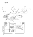
- FIG. 14 is a block diagram showing a configuration of a conventional photoelectric type yarn clearer.
- This yarn clearer 1 is disposed between a spinning section 40 and a take-up section 30 of each spinning unit 50 of spinning machine described in for example FIGs. 1 and 2.
- a cutter C for cutting yarn Y is provided upstream of the yarn clearer 1.
- the photoelectric type yarn clearer 1 comprises a detection head 1' consisting of a projecting section 2 and a light receiving section 3. It is configured to output voltage (electric current) corresponding to the amount of received light as a detection signal when the light receiving section 3 receives light projected from the projecting section 2.
- a relation between projecting voltage and light receiving voltage is expressed as in FIGs. 4 and 5.
- the projecting section 2 is composed of light emitting element such as LED and the light receiving section 3 is composed of photoelectric conversion element such as phototransistor.
- a photoelectric conversion element is supposed to have a property of increasing voltage level in substantially proportion to shadow size in examples described hereinafter.
- Y axis shown in FIGs. 4 and 5 represents light receiving voltage and the received light amount generally decreases because the yarn shadow increases as yarn thickness increases. On the contrary, the received light appears to increase in FIG. 5. This is because actual voltage is treated to purposely conduct operation for easy understanding.
- the cutter C is configured to activate by the output signal to cut yarn Y.
- the detection head 1' is connected to a control unit 4.
- the control unit 4 is composed of a microcomputer and provided with an A/D converting section 5, a yarn travel condition judging section 6, a light adjusting section 7 and a projecting voltage instruction value output section 15. Each element is later described in detail.
- the above mentioned yarn clearer 1 operates during yarn traveling time corresponding to time for taking up yarn.
- the yarn clearer 1 analyzes yarn quality including yarn thickness ⁇ and fluff size based on light receiving voltage signal input through the A/D converting section 5 in the yarn travel condition judging section 6 to detect yarn defects including abnormal twist application and slab.
- correction is performed in view of prevention of temperature drift and deterioration of the projection section 2 even during yarn traveling time, the correction is not regarded here because voltage level change involved with the correction is minimum but only correction during yarn travel stop time is regarded.
- a projection-side driving voltage (x in FIG. 4) is fixed at substantially constant level during yarn traveling time as described next.
- the photoelectric type yarn clearer 1 it is adjusted to set the light receiving voltage at the predetermined preset level (V 0 in FIG. 4) in the state of yarn travel stop on start-up (reference correction).
- This yarn travel stop state is set as a reference.
- the yarn clearer 1 judges yarn travel/stop state and detects yarn defects such as slab and analyzes yarn quality based on unevenness between a change of light receiving voltage with respect to a reference point, or the above mentioned predetermined preset level V 0 , and a light receiving voltage obtained during yarn travel.
- the projection-side driving voltage x is fixed at constant level regardless of yarn travel or stop as in FIG. 4.
- the light receiving voltage in the state of yarn stop is to be set at a predetermined preset level V 0 .
- Adjustment of the above mentioned projecting voltage x is performed using the control unit 4 in FIG. 14.
- the correcting section 8 compares the light receiving voltage level taken in from the A/D converting section 5 with the predetermined preset level V 0 previously stored in a preset level storing section 9. Subsequently the level of the projecting voltage x is controlled by the correcting section 8 so that the difference between both may be within the predetermined acceptable range. With this, the light receiving voltage is calibrated to the preset level V 0 and the projecting voltage corresponding to it is also fixed by the light adjustment section 7. The projection-side driving voltage x is decided in such way. And then the LED of the projecting section 2 is driven at the same voltage level in the case of shifting to the yarn travel state.
- the yarn travel condition judging section 6 monitors such light receiving voltage change during yarn travel and observes how different the light receiving voltage during yarn travel is from the reference point or the above mentioned predetermined preset level V 0 adjusted in the yarn travel stop state, based on the result of which yarn travel or stop is judged, different yarn number is detected, yarn defect including slab is detected and the yarn defect is analyzed.
- Patent Reference 1 compressed air is constantly sprayed around the detection head 1' immediately before the process of reference point correction to blow off and remove foreign objects and dirt deposited in the detection head 1', so that the state of the detection head 1' with foreign objects and dirt left is prevented (numeral references in FIG. 14 are used) .
- This compressed air is configured to spray through a cleaning nozzle 19 and a valve 18 controlled by a valve control section 17 of other controller but that of the yarn clearer 1.
- Patent Reference 1 Japanese Unexamined Patent Publication No. 10-305967
- Patent Reference 2 Japanese Unexamined Patent Publication No. 3-90639
- the present inventors found the solution of the above problems and achieved the present invention to provide a method for detecting dirt of detection heads in a plurality of yarn clearers, (1) which are mounted on a unit system comprising a plurality of spindles, for monitoring yarn quality and others of each spindle, wherein whether change of yarn thickness data ( ⁇ ) and/or yarn uniformity data (CV%) obtained based on yarn unevenness signals output from a yarn clearer of a specific spindle is attributed to change of monitored yarn property it self or to dirt of the above mentioned detection head is judged from a relation between yarn thickness data ( ⁇ ) and/or yarn uniformity data (CV%) obtained based on yarn unevenness signals output from the yarn clearer of the other spindle.
- ⁇ yarn thickness data
- CV% yarn uniformity data
- the present invention is the method for detecting dirt of detection heads in a plurality of yarn clearers, (2) which are mounted on a unit system comprising a plurality of spindles, for monitoring yarn quality and others of each spindle comprising steps of:
- the present invention is the method for detecting dirt of detection heads in a plurality of yarn clearers, (3) which are mounted on a unit system comprising a plurality of spindles, for monitoring yarn quality and others of each spindle comprising steps of,
- the present invention is the method for detecting dirt of detection heads in a plurality of yarn clearers, (4) which are mounted on a unit system comprising a plurality of spindles, for monitoring yarn quality and others of each spindle comprising steps of:
- the present invention enabling to solve the above mentioned problems is the system for detecting dirt of detection heads in a plurality of yarn clearers, (2)' which are mounted on a unit system comprising a plurality of spindles, for monitoring yarn quality and others, comprising:
- the present invention enabling to solve the above mentioned problems is the system for detecting dirt of detection heads in a Plurality of yarn clearers, (3)' which are mounted on a unit system comprising a plurality of spindles, for monitoring yarn quality and others, comprising:
- the present invention enabling to solve the above mentioned problems is the system for detecting dirt of detection heads in a Plurality of yarn clearers, (4)' which are mounted on a unit system comprising a plurality of spindles, for monitoring yarn quality and others, comprising:
- the method and system for detecting dirt of detection heads in yarn clearers may be combination of at least two out of the above mentioned (2) to (4) or (2)' to (4)'.
- yarn travel stop state As for the term “yarn travel stop state” in this description, recognition of yarn travel stop is generally referred to a state that no yarn unevenness signal (FW signal) from the yarn clearer is detected. That means, because signals output from the yarn clearer based on yarn thickness and fluff (hairiness) constantly change, no yarn travel is judged with no signal change.
- FW signal yarn unevenness signal
- yarn travel stop state refers to a state of recognition of the fact that yarn travel is not observed regardless of whether deposit, dirt, yarn etc. exist or not in the detection head. This shall include the following states:
- CV% represents yarn uniformity rate or variation rate of yarn thick unevenness within a predetermined interval (test length).
- N number of sampling
- V x individual yarn thickness ( ⁇ )
- V a mean value of yarn thickness ⁇ of n pieces of data
- ⁇ sum of n pieces of data.
- CV% obtained with this formula (1) corresponds to a monitor waveform of yarn thick-unevenness actually detected from the detection head of the yarn clearer as exemplified in FIGs. 4 and 5 described later. With this obtained CV%, variation rate against mean can be obtained with regard to a thickness detection value of yarn for a predetermined interval (test length L) of conducted detection.
- SD represents a standard deviation of continuous detection values corresponding to traveling yarn thick-unevenness. This SD is calculated with the following formula and corresponds to the previous value before being divided with the mean in calculation of the above mentioned CV%.
- SD obtained with this formula (2) corresponds to change rate (width) of yarn thick-unevenness or change width of monitor waveform of yarn thick-unevenness actually detected from the detection head as exemplified in FIGs. 4 and 5 later described.
- a method and system for detecting dirt in a detection head of photoelectric type yarn clearer which can detect the dirt of the yarn clearer head more quickly and accurately.
- more than one method out of them may be employed in a single unit of the system mentioned above. In this case, dirt detection performance on the yarn clearer head can be further improved. As mentioned later, there can be the case that ⁇ does not change despite a dirt head. If more than one method are employed together in that case, the detection head can detect dirt more accurately. And it is helpful for safer operation of a unit system.
- FIG. 1 is a diagram showing a configuration example of unit system.
- FIG. 2 is a diagram showing outline of a spinning machine.
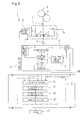
- FIG. 3 is a diagram showing a configuration example of a control system of a yarn clearer related to a first embodiment of the present invention.
- FIG. 4 is a diagram showing a relation between projecting voltage and light receiving voltage of the detection head in the yarn clearer.
- FIG. 5 is a diagram showing an example of yarn unevenness signal observed by the detection head in the yarn clearer.
- FIG. 6 is a diagram showing a relation between yarn thickness and uniformity (CV%).
- FIG. 1 is a diagram showing a configuration example of unit system.
- FIG. 2 is a diagram showing outline of a spinning machine.
- FIG. 3 is a diagram showing a configuration example of a control system of a yarn clearer related to a first embodiment of the present invention.
- FIG. 4 is a diagram showing a relation between projecting voltage and light receiving voltage of the detection head in the yarn clearer.
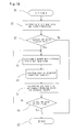
- FIG. 7 is a diagram showing a detection sequence related to the first embodiment of the present invention and an example of a flow chart when a yarn monitoring method of the present invention is performed with the configuration shown in FIG. 3.
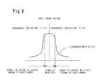
- FIG. 8 is a diagram showing a relation between variation (uneveness) ⁇ from CV% unit mean and threshold.
- FIG. 9 is a diagram showing a configuration example of a control system of the yarn clearer related to a second embodiment of the present invention.
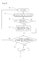
- FIG. 10 is a diagram showing a detection sequence related to the second embodiment of the present invention and an example of a flow chart when a yarn monitoring method of the present invention is performed with the configuration shown in FIG. 9.
- FIG. 11 is a diagram showing a configuration example of a control system of a yarn clearer related to a third embodiment of the present invention.
- FIG. 12 is a diagram showing a detection sequence related to the third embodiment of the present invention and an example of a flow chart when a yarn monitoring method of the present invention is performed with the configuration shown in FIG. 11.
- FIG. 13 is a diagram showing a method for detection head dirt in the third embodiment of the present invention.
- FIG. 14 is a block diagram showing a configuration of conventional photoelectric type yarn clearer. In the explanation below, the same elements shall have the same numeral references.
- FIG. 1 shows a configuration example of a control system of a unit system of a spinning machine applied to a method and a system related to the present invention for detecting dirt in a detection head of a photoelectric type yarn clearer.
- the yarn clearer is provided in front of piecing of a spinning device.
- unit system 100 as in FIG. 1 a single unit of yarn clearer monitors and judges four spindles. That means in the configuration of the yarn clearer 1 in the unit system 100 in FIG. 1, four units of detection heads 1' share a single unit of control unit 4.
- yarn clearers from No. 1 to No. 20 are provided in the unit system in FIG. 1 and a single unit system ends up handling total 80 spindles.
- Each yarn clearer is connected to a control master CM.
- control master CM In the control master CM, a unit mean of yarn thickness ⁇ is calculated and a CV% unit mean in each detection head is calculated as mentioned later.
- control master CM itself is connected to an operation data management system VOS for presenting to users information of various data including operation conditions, yarn quality control, operation control and maintenance control.
- VOS operation data management system
- MSMPC shown in FIG. 1 controls a spinning device of each spindle, controls cutters, and manages packages (constant length).
- FIG. 2 shows a portion of one spinning unit 50 out of a plurality of spinning units composing the unit system 100 in the spinning device related to the present invention.
- the yarn clearer 1 related to this embodiment is provided in a air type spinning machine.
- the air type spinning machine itself comprises a plurality of spinning units (80 units in this embodiment) arranged at even intervals in a vertical direction of a sheet FIG. 2.
- the spinning unit 50 is provided with a spinning section 40, the yarn clearer 1 and a take-up section 30 in order from upstream as in FIG. 2.
- an automatic piecing device not shown, is further provided, and after yarn defective portion detected by the yarn clearer 1 is cut and removed, spun yarn is pieced again so as to be continued to take up.
- the spinning section 40 in FIG. 2 is located upstream of the spinning unit 50 and yarn Y is spun out from a sliver (fiber bundle) S.
- the spinning section 40 is arranged with a draft part 45 comprising a back roller B, a middle roller M, and a front roller F, an air spinning nozzle A, and yarn feed roller D in this order from the sliver S.
- the middle rollers M are wound with apron E formed of no end rubber belt.
- Each roller B, M, F respectively comprises an upper top roller and a lower bottom roller and drafts the sliver S.
- the air spinning nozzle A twists the sliver S output from the front roller F to produce spun yarn Y.
- the yarn feed roller D draws yarn from the spinning nozzle A.
- the take-up section 30 is disposed downmost of the spinning unit 50.
- the take-up section 30 is contacted with pressure to a peripheral surface of the package P to rotation drive the package P to take up the spun yarn Y, and composed of a dram T driven by a motor, not shown.
- the yarn clearer 1 is disposed between the above mentioned spinning section 40 and the take-up section 30 for detecting yarn conditions and removing a defective portion.
- the yarn clearer 1 is a photoelectric type yarn monitoring device to detect variation of diameter of yarn Y (yarn thickness ⁇ ) spun by each spinning unit 50 and output yarn unevenness signal and the like.
- a cutter C for cutting yarn Y is provided upstream of the yarn clearer 1.
- a cleaning nozzle 19 is provided near an upper face of the yarn clearer 1. An opening at one end of the cleaning nozzle 19 is arranged so as to face to the upper face of the yarn clearer 1.
- the onother end of the cleaning nozzle 19 is connected with an air spraying device, not shown.
- the air spraying device is configured to spray compressed air from the opening at one end of the cleaning nozzle 19 to blow off and remove cotton fly and dirt adhered to the detection head of the yarn clearer 1, foreign objects and dirt including yarn wastes, or yarn Y hung on the yarn clearer 1 following the conventional control method.
- FIG. 3 shows a configuration of a light projecting/receiving system of the yarn clearer.
- the light projecting/receiving system of the yarn clearer related to this embodiment is provided with LED on the light projecting side, provided with a light receiving element on the light receiving side, and a glass surface (cover glass), not shown, is provided between the light projecting element and the light receiving element which are facing to each other to prevent the both elements from adhering traveling filament, fluff and the like.
- cover glass cover glass
- the control unit 4 connected to the detection head 1' is composed of a micro computer and provided with a A/D converting section 5, a yarn travel condition judging section 6, a light adjusting section 7, and a light projecting voltage instruction value output section 15.
- the light projecting voltage instruction value output section 15 is composed a F/V converting section or a D/A converting section later mentioned.
- the A/D converting section 5 is connected to the light receiving section 3 of the detection head 1' and has a function to convert analog signals input from the light receiving section 3 to digital signals.
- the yarn travel condition judging section 6 is connected to the A/D converting section 5 and judges travel or stop of yarn Y by observing light receiving voltage signal from the A/D converting section.
- a phototransistor detects minimum changes of yarn thickness (yarn unevenness) during yarn travel to express amplitude in a light receiving voltage waveform (Ref. to FIGs. 4 and 5) .
- This embodiment is configured to judge travel or stop of yarn Y using this property. More particularly, it it judged as yarn travel if the above mentioned amplitude (yarn unevenness signal) is detected for predetermined time, while it is judged as yarn stop if such amplitude is not detected for the predetermined time.
- the light adjusting section 7 composed of a correcting section 8 and a preset value storing section 9.
- the correcting section 8 have a function to compare light receiving voltage input from A/D converting section 5 to the correcting section 8 with predetermined preset value (V 0 in FIG. 4) previously stored in the preset storing section 9 and to calibrate driving signal to the light projecting section 2 to adjust light projecting voltage (x in FIG. 4) (reference pint correction) so that light receiving voltage becomes a preset value V 0 at yarn stop state.
- predetermined preset value V 0 is set 0.1V in this embodiment and previously input from an input section 13 provided outside to the control means 4, and stored.
- the input section 13 corresponds to an operation panel of data management system VOS of unit system 100.
- This correcting section 8 outputs a value of the projection-side driving voltage x, after reference point correction is performed, to the light projecting voltage instructing section 15.
- the correcting section 8 of the light adjusting section 7 is a pulse output section, has a function to output a driving pulse at arbitrary output frequency f, and is connected to the light projecting voltage instructing value output section 15. This is because the light projecting voltage instructing value output section 15 is configured as the F/V converting section.
- the light projecting voltage instructing value output section 15 composed of the F/V converting section and configured to output the voltage signals corresponding to the output frequency f and input to a variable voltage source 16.
- the variable voltage source 16 is connected to the light projecting section 2 of the detection head 1' and applies voltage corresponding to signals from the light projecting voltage instructing value output section 15 to LED of the light projecting section 2.
- the configuration of light projecting voltage instructing value output section 15 is not limited to this and may be configured as a D/A converter.
- the head dirt detecting section 20 comprises: a ⁇ detecting section 21 which is connected to light receiving side of each spindle and is input with ⁇ data from the A/D converting section 5 of the control unit 4 connected to each detection head 1' ; a CV% calculating section 23 which is also connected to light receiving side of each spindle and calculate a CV% value in each spindle; a ⁇ unit mean calculating section 22 which is connected to the ⁇ detecting section 21 and calculates a unit mean based on ⁇ data input in the ⁇ detecting section 21 from each spindle; a unit mean calculating section 24 which is connected to the CV% calculating section 23 and calculates CV% unit mean based on CV% in each spindle; a standard deviation calculating section 25 which is connected to the CV% unit mean calculating section 24 and calculates a unit overall
- the comparing section 26 is further connected to an alarm 27.
- the comparing section 26 as mentioned below is directly or indirectly connected at least to the ⁇ detecting section 21, a ⁇ unit mean calculating section 22, the CV% calculating section 23, the CV% unit mean calculating section 24, and the standard deviation calculating section 25, and proceeds steps of:
- the head dirt detection sequence is performed for the detection head 1' of this embodiment through interactions between the control unit 4 and control master CM.
- the spinning machine starts operation, yarn Y is spun from the spinning section 40 comprising the draft part 45 and the air spinning nozzle A, this yarn Y is sent and taken up to a package P by the take-up section 30 while the yarn clearer 1 detecting conditions of the yarn Y.
- this spinning operation stats, in the yarn clearer 1, as shown in FIGs. 4 and 5, a yarn travel/stop state is judged based on output signals from the light receiving element of the detection head 1', analysis of yarn quality including fluff amount starts, and uniformity analysis and judgment of slab and yarn defects are conducted.
- detection sequence of detection head dirt as exemplified in FIG.
- the head dirt detection sequence related to the first embodiment of the present invention is continued to describe with reference to a flow chart of FIG. 7 and diagrams showing one example of signals of yarn unevenness observed by the light receiving system of the detection head in the yarn clearer shown in FIGs. 4 and 5.
- ⁇ data extracted from each spindle is collected to the control master CM where analysis is performed with respect to each spindle to identify a spindle with a dirt head. Therefore, as in FIG. 3, the judging means related to this first embodiment should be provided to each spindle of the unit system 100 and the control master CM entirely.
- the light projecting/receiving system in the ordinary conditions is described.
- reference point correction is performed at appropriate intervals so that in basic LED output on projection side, a light receiving level is set to be 0.1V in the state of broken yarn, as shown on left end of FIG. 5 (A) to (C). Thickness ⁇ (mean value) of the traveling filament is grasped by obtaining mean level of yarn unevenness signals obtained in the light receiving element 3 as shown in FIG. 5. A swing width of yarn unevenness signals changes according to existence or degree of fluff.
- a reference value of the signal level for given yarn thickness is stored in the first storing section as predetermined threshold (the first threshold) preset based on the ⁇ unit mean.
- Step S1 is executed by the ⁇ detecting section 21, and Step S2 is executed by the ⁇ unit mean calculating section 22.
- Step S1 and Step S2 as mentioned below, CV% of each spindle is calculated (Step S1), CV% unit mean value, and unit overall standard deviation based on the mean value is calculated (Step 2) in parallel.
- the CV% calculation of Step S1 is executed by the CV% calculating section 23 and the calculation of CV% unit mean value of Step S2 is executed by CV% unit mean value calculating section 24, and the calculation of standard deviation obtained based on the mean value is executed by the standard deviation calculating section 25.
- Step S1 the yarn thickness value ⁇ of each spindle detected in Step S1 is compared with the first threshold preset based on the ⁇ unit mean value in Step 2 (S3).
- This Step 3 is executed by the comparing section 26 using the first threshold stored in the first storing section.
- Step S3 when the yarn thickness value ⁇ of the specific spindle is judged to be larger than the first threshold, next, unevenness ⁇ from the unit mean of CV% value of the specific spindle is calculated based on the CV% value of each spindle, the CV% unit mean and the unit overall standard deviation obtained from this CV% value unit mean (S4) .
- This Step 4 is executed by the comparing section 26. And when the result of the comparison in Step 3 is judged No, there is no possibility of different yarn number or dirty head, and again detection/calculation in Step S1 and S2 are repeated.
- Step 4 the value ⁇ obtained in Step 4 is compared to see within a predetermined range of upper limit value and lower limit value (the second threshold) preset based on the CV% unit mean and the unit overall standard deviation obtained from this CV% unit mean.
- This Step 5 is also executed by the comparing section 26 using the upper/lower limit (the second threshold) stored in the second storing section in the comparing section 26.
- Step S5 the relation between unevenness ⁇ from CV% unit mean and threshold is shown in FIG. 8 as a reference.
- output level change from the light receiving element judges whether i) the yarn number actually changes or ii) the head is simply dirty.
- FIG. 9 is a diagram showing a configuration of a yarn clearer related to the second embodiment of the present invention.
- FIG. 10 is a diagram showing a detection sequence of the head dirt related to the second embodiment of the present invention. The sequence related to FIG. 10, ⁇ data is extracted from each spindle and collected in the control master CM and analyzed to identify the spindle with head dirt by calculation.
- the method related to the second embodiment related to the present invention is a judging method employing indicator of unevenness (deviation) among a plurality of spindles provided in a single unit system and outlined as below. This judgment may be executed by the control master CM as mentioned above. Therefore, one set of this judging method prepared is enough for one unit system.
- the head dirt detecting section 20' comprises: a ⁇ detecting section 21 which is connected to light receiving side of each spindle and is input with ⁇ data from an A/D converting section 5 of a control unit 4 connected to each detection head 1' ; a ⁇ unit mean calculating section 22 which is connected to the ⁇ detecting section 21 and calculates a ⁇ unit mean based on ⁇ data input in the ⁇ detecting section 21 from each spindle; a standard deviation calculating section 25' which is connected to the ⁇ unit mean calculating section 22 and calculates a unit overall standard deviation SD based on the obtained ⁇ unit mean; a third storing section stores in the next comparing section 26' a predetermined preset value (third threshold) set based on the standard deviation obtained by the standard deviation calculating section 25'; and a comparing section
- ⁇ data measured for each spindle is collected in a control master CM, and then the ⁇ unit mean and unevenness among spindles in the unit overall (S0, S1 in FIG. 10). These steps S0, S1 are executed by the ⁇ unit mean calculating section 22 and the standard deviation calculating section 25' .
- the standard deviation SD is used as an indicator of unevenness among spindles.
- Step S2 is executed by the comparing section 26'using the standard deviation SD obtained by the standard deviation calculating section 25' and the third threshold stored in the third storing section.
- Step S2 when the standard deviation is smaller than the third threshold, it is judged that there is no spindles with head dirt in this unit and the sequence to find spindles with head dirt related to this embodiment is completed (S7).
- Step S2 when the standard deviation value is larger than the third threshold, the yarn thickness ⁇ measured in each spindle and the ⁇ unit mean calculated before are compared and the spindle whose value is most different from the ⁇ unit mean is extracted in calculation (S3).
- the spindle state extracted here is regarded as "head dirt" and spindles are excluded in descending order of difference from the unit mean with respect to ⁇ value, and then the ⁇ unit mean and unevenness among spindles in the unit overall are recalculated (S4, S5) .
- Step S3 and Step S4 are executed by the comparing section 26' and Step S5 is executed by the ⁇ unit mean calculating section 22 and the standard deviation calculating section 25'.
- the spindle having big difference from the ⁇ unit mean value is judged as "spindle with head dirt" and the spindle is excluded from the calculation of the ⁇ unit mean and the unit overall standard deviation.
- Step S6 When the standard deviation calculated after the above mentioned exclusion is still larger than the third threshold (the result of Step S6 is No), the spindle having the second biggest difference in ⁇ value from the unit mean is also judged as "spindle with head dirt" (repetition of S3 and S4), the spindle is excluded from the calculation of the ⁇ unit mean and the unit overall standard deviation, and the standard deviation is newly recalculated (repetition of S5 and S6) .
- This step S6 is executed by the comparing section 26'.
- spindles having big different ⁇ value from the unit mean are excluded until the standard deviation becomes smaller than the predetermined preset value (the third threshold) (repetition of Steps S3 to S6).
- Step S6 the sequence to seek spindles with head dirt is completed (S7).
- one or more spindles excluded from the calculation by the completion of the sequence are judged as "spindles with head dirt". The effect that these spindles excluded from the calculation have head dirt is informed to users from the comparing section 26' through the alarm 27.
- FIG. 11 is a diagram showing a configuration of a yarn clearer related to the third embodiment of the present invention.
- FIG. 12 is a diagram showing a detection sequence of the spindle with head dirt related to the third embodiment of the present invention.
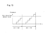
- FIG. 13 is a diagram showing a method for detection head dirt related to the third embodiment of the present invention. The sequence related to FIG. 12, CV% data in each spindle is collected in the control master CM, and analyzed and compared on the basis of the calculation value to identify the spindle with head dirt.
- the third embodiment of the present invention is a judgment method employing an indicator called HD.
- HD is one of indictors called hairiness (fluff) data expressing yarn quality and indicates data for given length from the period yarn is hung.
- spindle with head dirt is identified by observing two indicators of i) HD alarm frequency and ii) CV% value.
- the third embodiment of the present invention is outlined.
- the spindle in which i) HD alarms (or cut due to the alarm) occur more often than preset frequency within given unit time and ii) the CV% value of the spindle is within the predetermined range of upper limit/lower limit (fourth threshold) preset based on CV% unit mean and unit overall standard deviation obtained from this CV% unit mean, the spindle is judged as a spindle with head dirt and head cleaning by the operator is requested.
- the head dirt detecting section 20" comprises: an HD monitoring section 28 which is connected to light receiving side of each spindle and monitors an indicator HD of each spindle from ⁇ data from an A/D converting section 5 of a control unit 4 connected to each detection head 1'; a CV% calculating section 23 which is connected to light receiving side of each spindle and calculates CV% value of each spindle; a CV% unit mean calculating section 24 which is connected to the CV% calculating section 23 and calculates CV% unit mean value based on CV% value of each spindle; a standard deviation calculating section 25 which is connected to the CV% unit mean calculating section 24 and calculates a unit overall standard deviation SD based on the CV% unit mean; and a comparing section 26" which is directly or indirectly connected at least to the HD
- Step S2 When the judgment result of Step S2 is No, the spindle is regarded as a spindle with no head dirt, the sequence is completed, the sequence is returned to the beginning, and HD alarm occurence is monitored by the HD monitoring section 28 (S1). And when the judgment result of Step 2 is No, addition of the number of HD alarm detection for dirt detection of Step S3 is skipped. For this reason, a judgment process related to Step 4 is also skipped and a process is performed in assumption of No with regard to the result of Step S4.
- Step S3 is executed interior of the comparing section 26".
- Step S4 after addition in Step S3, whether or not the number of HD alarm detection for dirt detection per unit time for a given spindle exceeds the preset frequency is judged (ref. to FIG. 13).
- a process returned to the beginning to monitor HD alarm occurrence (S1).
- the above mentioned preset frequency value and the preset value are also stored in the comparing section 26".
- the head dirt spindle detection sequence related to this embodiment is executed every time an HD alarm occurs after the spinning device starts operation and the number of detections in Step S3 are accumulated. Therefore, this sequence is executed several times, the number of detections in Step S3 are accumulated and recorded interior of the comparing section 26".
- Step S4 When the result of Step S4 is Yes, that means, when the number of HD alarm detections for dirt detection per unit time finally exceeds the preset frequency value, the spindle is judged as a spindle with head dirt and head cleaning by operators is requested and this sequence is finished (S5) .
- the effect that the spindle having the number of HD alarm detections for dirt detection per unit time exceeding the preset frequency value is a spindle with head dirt is informed to users from the comparing section 26" through the alarm 27. Frequent occurrences of these HD alarms or cuts within unit time is considered because of frequent occurrences of wasteful cuts due to error detection related to HD in one example.
- the present invention exemplified by the first embodiment to the third embodiment as previously mentioned, for example, it is possible to quickly and securely detect the dirt of the detection head in such that the dirt is firmly adhered to a glass surface between the light projecting/receiving elements and can not be removed by means such as air spray but can be removed only by an alcohol-soaked cotton swab and the like.
- the method or the system of the present invention for detecting dirt of the detection head in the photoelectric type yarn clearer may be a combination of two or more of the first embodiment to the third embodiment, which can further improve dirt detection performance of the detection head.
- the number of detection heads mounted per a single unit of yarn clearer is not limited to the above. And the number of yarn clearers mounted per a single unit system is also same.
- the method and the system of the present invention for detecting dirt of the detection head in the photoelectric type yarn clearer is applied to the spinning machine provided with the air type spinning section.
- subject to be applied is not limited to such spinning machine, but the present invention can be applied to ones provided with various type spinning sections except for air type, and textile machines such as an automatic winder and a stranding machine.
- the light projecting voltage instruction output section 15 is the F/V converting section to output the driving voltage corresponding to output frequency f of the driving pulse to the variable voltage source 16.
- the light projecting voltage instruction output section 15 is not limited to this configuration. That means, as shown in FIGs. 3, 9, 11 and 14, the light projecting voltage instruction output section 15 may be formed as e.g. D/A converter.
- the correcting section 8 of the light adjusting section 7 is formed as a counter of microcomputer.
- the correcting section 8 changes output signals by not shown clock signals and data (counter value) corresponding to desired light projecting voltage input in the counter according to the result of the reference point correction and send them out to the light projecting voltage instruction output section 15.
- output signals made out in the correcting section 8 are subject to D/A conversion and sent out to the variable voltage source 16.
- the variable voltage source 16 increases or decreases LED emission amount of the light projecting section 2 based on the signals output form the light projecting voltage instruction output section 15.
- alarm is emitted to users when the spindle is judged as a spindle with head dirt.
- the treatment is not limited to this, for example, the spinning unit 50 may be shutdown. Furthermore, treatment may be in combination with cleaning utilizing a compressed air valve and the like.
- the present invention provides a novel and useful method and system for detecting dirt of a detection head in a yarn clearer.
- FIG. 1 is a diagram showing one configuration example of unit system.
- FIG. 2 is a diagram showing outline of a spinning machine.
- FIG. 3 is a diagram showing one configuration example of a control system of a yarn clearer related to a first embodiment of the present invention.
- FIG. 4 is a diagram showing a relation between light projecting voltage and light receiving voltage of the detection head in the yarn clearer.
- FIG. 5 is a diagram showing an example of yarn unevenness signals observed by the detection head in the yarn clearer.
- FIG. 6 is a diagram showing a relation between yarn thickness and uniformity (CV%).
- FIG. 7 is a diagram showing a detection sequence related to the first embodiment of the present invention and an example of a flow chart when a yarn monitoring method of the present invention is performed with the configuration shown in FIG. 3.
- FIG. 7 is a diagram showing a detection sequence related to the first embodiment of the present invention and an example of a flow chart when a yarn monitoring method of the present invention is performed with the configuration shown in FIG. 3.
- FIG. 8 is a diagram showing a relation between variation ⁇ from CV% unit mean value and threshold.
- FIG. 9 is a diagram showing one configuration example of the control system of the yarn clearer related to a second embodiment of the present invention.
- FIG. 10 is a diagram showing a detection sequence related to the second embodiment of the present invention and an example of a flow chart when a yarn monitoring method of the present invention is performed with the configuration shown in FIG. 9.
- FIG. 11 is a diagram showing one configuration example of the control system of the yarn clearer related to a third embodiment of the present invention.
- FIG. 12 is a diagram showing a detection sequence related to the third embodiment of the present invention and an example of a flow chart when a yarn monitoring method of the present invention is performed with the configuration shown in FIG. 11.
- FIG. 13 is a diagram showing a method for detection head dirt in the third embodiment of the present invention.
- FIG. 14 is a block diagram showing a configuration of conventional photoelectric type yarn clearer.
Landscapes
- Engineering & Computer Science (AREA)
- Textile Engineering (AREA)
- Mechanical Engineering (AREA)
- Quality & Reliability (AREA)
- Physics & Mathematics (AREA)
- General Physics & Mathematics (AREA)
- Spinning Or Twisting Of Yarns (AREA)
- Filamentary Materials, Packages, And Safety Devices Therefor (AREA)
Applications Claiming Priority (1)
| Application Number | Priority Date | Filing Date | Title |
|---|---|---|---|
| JP2006176293A JP2008007214A (ja) | 2006-06-27 | 2006-06-27 | ヤーンクリアラの検出ヘッドの汚れ検出方法及び検出システム |
Publications (2)
| Publication Number | Publication Date |
|---|---|
| EP1873105A2 true EP1873105A2 (de) | 2008-01-02 |
| EP1873105A3 EP1873105A3 (de) | 2008-10-01 |
Family
ID=38626698
Family Applications (1)
| Application Number | Title | Priority Date | Filing Date |
|---|---|---|---|
| EP07111082A Withdrawn EP1873105A3 (de) | 2006-06-27 | 2007-06-26 | Verfahren zum Erkennen von Verschmutzung auf einem Detektionskopf eines Fadenreinigers und System dafür |
Country Status (2)
| Country | Link |
|---|---|
| EP (1) | EP1873105A3 (de) |
| JP (1) | JP2008007214A (de) |
Cited By (5)
| Publication number | Priority date | Publication date | Assignee | Title |
|---|---|---|---|---|
| CN104499132A (zh) * | 2015-01-15 | 2015-04-08 | 无锡北斗星通信息科技有限公司 | 一种用于控制纱线质量的纺纱机清纱方法 |
| CN104532423A (zh) * | 2015-01-15 | 2015-04-22 | 无锡北斗星通信息科技有限公司 | 一种基于图像识别的纱线质量测控方法 |
| WO2019130209A3 (en) * | 2017-12-26 | 2019-08-08 | Petr Perner | Devices and methods for yarn quality monitoring |
| US10605798B2 (en) | 2017-12-26 | 2020-03-31 | Petr PERNER | Method and device for optical yarn quality monitoring |
| CN111235709A (zh) * | 2020-03-18 | 2020-06-05 | 东华大学 | 一种基于机器视觉的环锭纺细纱条干在线检测系统 |
Families Citing this family (4)
| Publication number | Priority date | Publication date | Assignee | Title |
|---|---|---|---|---|
| EP2651802B1 (de) * | 2010-12-13 | 2015-02-25 | Uster Technologies AG | Diagnoseverfahren für eine textile messvorrichtung |
| JP5870810B2 (ja) | 2012-03-28 | 2016-03-01 | 村田機械株式会社 | 糸走行情報取得装置および糸処理装置 |
| JP2020001837A (ja) | 2018-06-25 | 2020-01-09 | 村田機械株式会社 | 番手異常検出方法、繊維処理システム、紡績機、番手異常検出プログラム |
| CN113533357B (zh) * | 2020-04-16 | 2023-09-29 | 杭州慧知连科技有限公司 | 丝锭表面缺陷视觉检测方法及其检测装置 |
Citations (5)
| Publication number | Priority date | Publication date | Assignee | Title |
|---|---|---|---|---|
| EP0271728A2 (de) * | 1986-12-06 | 1988-06-22 | Robert Prof. Dr. Massen | Verfahren zur Messung und/oder Überwachung von Eigenschaften von Garnen oder Seilen |
| US4924406A (en) * | 1985-10-16 | 1990-05-08 | Nuovopignone Industrie Meccanichee Fonderia S.p.A. | Optical slub catcher, particularly suitable for openend process |
| US5210735A (en) * | 1989-06-23 | 1993-05-11 | Hitachi, Ltd. | Optical recording/reproducing system, having function of detecting dirt deposition on optical pickup |
| EP0907079A1 (de) * | 1997-10-02 | 1999-04-07 | Murata Kikai Kabushiki Kaisha | Vorrichtung zur Qualitätskontrolle eines texturiertem Filamentgarn |
| EP0945533A1 (de) * | 1998-03-25 | 1999-09-29 | Zellweger Luwa Ag | Vorrichtung zum Messen von Eigenschaften eines längsbewegten Prüfguts |
-
2006
- 2006-06-27 JP JP2006176293A patent/JP2008007214A/ja active Pending
-
2007
- 2007-06-26 EP EP07111082A patent/EP1873105A3/de not_active Withdrawn
Patent Citations (5)
| Publication number | Priority date | Publication date | Assignee | Title |
|---|---|---|---|---|
| US4924406A (en) * | 1985-10-16 | 1990-05-08 | Nuovopignone Industrie Meccanichee Fonderia S.p.A. | Optical slub catcher, particularly suitable for openend process |
| EP0271728A2 (de) * | 1986-12-06 | 1988-06-22 | Robert Prof. Dr. Massen | Verfahren zur Messung und/oder Überwachung von Eigenschaften von Garnen oder Seilen |
| US5210735A (en) * | 1989-06-23 | 1993-05-11 | Hitachi, Ltd. | Optical recording/reproducing system, having function of detecting dirt deposition on optical pickup |
| EP0907079A1 (de) * | 1997-10-02 | 1999-04-07 | Murata Kikai Kabushiki Kaisha | Vorrichtung zur Qualitätskontrolle eines texturiertem Filamentgarn |
| EP0945533A1 (de) * | 1998-03-25 | 1999-09-29 | Zellweger Luwa Ag | Vorrichtung zum Messen von Eigenschaften eines längsbewegten Prüfguts |
Cited By (6)
| Publication number | Priority date | Publication date | Assignee | Title |
|---|---|---|---|---|
| CN104499132A (zh) * | 2015-01-15 | 2015-04-08 | 无锡北斗星通信息科技有限公司 | 一种用于控制纱线质量的纺纱机清纱方法 |
| CN104532423A (zh) * | 2015-01-15 | 2015-04-22 | 无锡北斗星通信息科技有限公司 | 一种基于图像识别的纱线质量测控方法 |
| WO2019130209A3 (en) * | 2017-12-26 | 2019-08-08 | Petr Perner | Devices and methods for yarn quality monitoring |
| US10605798B2 (en) | 2017-12-26 | 2020-03-31 | Petr PERNER | Method and device for optical yarn quality monitoring |
| CN111670358A (zh) * | 2017-12-26 | 2020-09-15 | 彼得·佩纳 | 用于纱线质量监测的装置和方法 |
| CN111235709A (zh) * | 2020-03-18 | 2020-06-05 | 东华大学 | 一种基于机器视觉的环锭纺细纱条干在线检测系统 |
Also Published As
| Publication number | Publication date |
|---|---|
| JP2008007214A (ja) | 2008-01-17 |
| EP1873105A3 (de) | 2008-10-01 |
Similar Documents
| Publication | Publication Date | Title |
|---|---|---|
| EP1873105A2 (de) | Verfahren zum Erkennen von Verschmutzung auf einem Detektionskopf eines Fadenreinigers und System dafür | |
| EP3293295B1 (de) | Messsystem für eine maschine zur verarbeitung eines fasertextilmaterials | |
| EP2107141A2 (de) | Spinnvorrichtung | |
| US11319649B2 (en) | Ring spinning system and method for operating | |
| EP2354069A2 (de) | Garnwicklungsmaschine | |
| EP2169097B1 (de) | Fremdstoff erfassungsvorrichtung und -verfahren in textilmaschine | |
| EP3708700A1 (de) | Roving-rahmen mit einem überwachungssystem | |
| JP4049107B2 (ja) | 紡績機における繊維束の品質管理方法 | |
| CN103025937B (zh) | 纺织机 | |
| CN103510217A (zh) | 纤维机械及纤维机械的周期性不匀检测方法 | |
| CN103359544A (zh) | 纱线行进信息获取装置及纱线处理装置 | |
| US11814755B2 (en) | Method of contactless optical detection of yarn at a workstation of a yarn manufacturing textile machine, an optical sensor of yarn and a textile machine | |
| EP3438334B1 (de) | Luftspinnmaschine und anzeigesteuerungsverfahren | |
| JP2007131974A (ja) | 糸品質診断方法および繊維機械 | |
| JP2005299037A (ja) | 紡績糸監視方法及び繊維機械 | |
| JP2007224452A (ja) | 異常錘特定装置および紡績機 | |
| EP3686330B1 (de) | Spinnverfahren, spinnmaschine und spinnprogramm | |
| EP3587632A1 (de) | Anomaliedetektionsverfahren, faserverarbeitungssystem, spinnmaschine und anomaliedetektionsprogramm | |
| CN112442768B (zh) | 纺纱机的管理装置以及带管理装置的纺纱机 | |
| JP2005232650A (ja) | 糸監視方法及びその装置 | |
| JP6459033B2 (ja) | 糸監視装置及び糸巻取機 | |
| CN112593316B (zh) | 计算装置、空气纺纱机以及纤维屑产生量输出方法 | |
| JPS6052219B2 (ja) | 紡績機の糸品質管理装置 | |
| CN113979220A (zh) | 纱线卷取机以及卷取异常检测方法 | |
| JP3551823B2 (ja) | 紡績機の糸品質監視装置 |
Legal Events
| Date | Code | Title | Description |
|---|---|---|---|
| PUAI | Public reference made under article 153(3) epc to a published international application that has entered the european phase |
Free format text: ORIGINAL CODE: 0009012 |
|
| AK | Designated contracting states |
Kind code of ref document: A2 Designated state(s): AT BE BG CH CY CZ DE DK EE ES FI FR GB GR HU IE IS IT LI LT LU LV MC MT NL PL PT RO SE SI SK TR |
|
| AX | Request for extension of the european patent |
Extension state: AL BA HR MK YU |
|
| PUAL | Search report despatched |
Free format text: ORIGINAL CODE: 0009013 |
|
| AK | Designated contracting states |
Kind code of ref document: A3 Designated state(s): AT BE BG CH CY CZ DE DK EE ES FI FR GB GR HU IE IS IT LI LT LU LV MC MT NL PL PT RO SE SI SK TR |
|
| AX | Request for extension of the european patent |
Extension state: AL BA HR MK RS |
|
| 17P | Request for examination filed |
Effective date: 20081117 |
|
| 17Q | First examination report despatched |
Effective date: 20081230 |
|
| AKX | Designation fees paid |
Designated state(s): CH DE LI |
|
| STAA | Information on the status of an ep patent application or granted ep patent |
Free format text: STATUS: THE APPLICATION IS DEEMED TO BE WITHDRAWN |
|
| 18D | Application deemed to be withdrawn |
Effective date: 20090512 |