EP1872368B1 - Device and method for determining a point in a film - Google Patents
Device and method for determining a point in a film Download PDFInfo
- Publication number
- EP1872368B1 EP1872368B1 EP06743144A EP06743144A EP1872368B1 EP 1872368 B1 EP1872368 B1 EP 1872368B1 EP 06743144 A EP06743144 A EP 06743144A EP 06743144 A EP06743144 A EP 06743144A EP 1872368 B1 EP1872368 B1 EP 1872368B1
- Authority
- EP
- European Patent Office
- Prior art keywords
- film
- search window
- signal
- time
- sampling rate
- Prior art date
- Legal status (The legal status is an assumption and is not a legal conclusion. Google has not performed a legal analysis and makes no representation as to the accuracy of the status listed.)
- Expired - Fee Related
Links
Images


Classifications
-
- G—PHYSICS
- G03—PHOTOGRAPHY; CINEMATOGRAPHY; ANALOGOUS TECHNIQUES USING WAVES OTHER THAN OPTICAL WAVES; ELECTROGRAPHY; HOLOGRAPHY
- G03B—APPARATUS OR ARRANGEMENTS FOR TAKING PHOTOGRAPHS OR FOR PROJECTING OR VIEWING THEM; APPARATUS OR ARRANGEMENTS EMPLOYING ANALOGOUS TECHNIQUES USING WAVES OTHER THAN OPTICAL WAVES; ACCESSORIES THEREFOR
- G03B31/00—Associated working of cameras or projectors with sound-recording or sound-reproducing means
- G03B31/02—Associated working of cameras or projectors with sound-recording or sound-reproducing means in which sound track is on a moving-picture film
-
- G—PHYSICS
- G03—PHOTOGRAPHY; CINEMATOGRAPHY; ANALOGOUS TECHNIQUES USING WAVES OTHER THAN OPTICAL WAVES; ELECTROGRAPHY; HOLOGRAPHY
- G03B—APPARATUS OR ARRANGEMENTS FOR TAKING PHOTOGRAPHS OR FOR PROJECTING OR VIEWING THEM; APPARATUS OR ARRANGEMENTS EMPLOYING ANALOGOUS TECHNIQUES USING WAVES OTHER THAN OPTICAL WAVES; ACCESSORIES THEREFOR
- G03B27/00—Photographic printing apparatus
- G03B27/02—Exposure apparatus for contact printing
- G03B27/04—Copying apparatus without a relative movement between the original and the light source during exposure, e.g. printing frame or printing box
- G03B27/08—Copying apparatus without a relative movement between the original and the light source during exposure, e.g. printing frame or printing box for automatic copying of several originals one after the other, e.g. for copying cinematograph film
-
- G—PHYSICS
- G03—PHOTOGRAPHY; CINEMATOGRAPHY; ANALOGOUS TECHNIQUES USING WAVES OTHER THAN OPTICAL WAVES; ELECTROGRAPHY; HOLOGRAPHY
- G03B—APPARATUS OR ARRANGEMENTS FOR TAKING PHOTOGRAPHS OR FOR PROJECTING OR VIEWING THEM; APPARATUS OR ARRANGEMENTS EMPLOYING ANALOGOUS TECHNIQUES USING WAVES OTHER THAN OPTICAL WAVES; ACCESSORIES THEREFOR
- G03B27/00—Photographic printing apparatus
- G03B27/32—Projection printing apparatus, e.g. enlarger, copying camera
- G03B27/52—Details
- G03B27/521—Arrangements for applying a supplementary information onto the sensitive material, e.g. coding
-
- G—PHYSICS
- G03—PHOTOGRAPHY; CINEMATOGRAPHY; ANALOGOUS TECHNIQUES USING WAVES OTHER THAN OPTICAL WAVES; ELECTROGRAPHY; HOLOGRAPHY
- G03B—APPARATUS OR ARRANGEMENTS FOR TAKING PHOTOGRAPHS OR FOR PROJECTING OR VIEWING THEM; APPARATUS OR ARRANGEMENTS EMPLOYING ANALOGOUS TECHNIQUES USING WAVES OTHER THAN OPTICAL WAVES; ACCESSORIES THEREFOR
- G03B31/00—Associated working of cameras or projectors with sound-recording or sound-reproducing means
- G03B31/04—Associated working of cameras or projectors with sound-recording or sound-reproducing means in which sound track is not on, but is synchronised with, a moving-picture film
-
- G—PHYSICS
- G11—INFORMATION STORAGE
- G11B—INFORMATION STORAGE BASED ON RELATIVE MOVEMENT BETWEEN RECORD CARRIER AND TRANSDUCER
- G11B20/00—Signal processing not specific to the method of recording or reproducing; Circuits therefor
- G11B20/10—Digital recording or reproducing
- G11B20/10009—Improvement or modification of read or write signals
- G11B20/10037—A/D conversion, D/A conversion, sampling, slicing and digital quantisation or adjusting parameters thereof
-
- G—PHYSICS
- G11—INFORMATION STORAGE
- G11B—INFORMATION STORAGE BASED ON RELATIVE MOVEMENT BETWEEN RECORD CARRIER AND TRANSDUCER
- G11B20/00—Signal processing not specific to the method of recording or reproducing; Circuits therefor
- G11B20/10—Digital recording or reproducing
- G11B20/10527—Audio or video recording; Data buffering arrangements
-
- G—PHYSICS
- G11—INFORMATION STORAGE
- G11B—INFORMATION STORAGE BASED ON RELATIVE MOVEMENT BETWEEN RECORD CARRIER AND TRANSDUCER
- G11B20/00—Signal processing not specific to the method of recording or reproducing; Circuits therefor
- G11B20/10—Digital recording or reproducing
- G11B20/12—Formatting, e.g. arrangement of data block or words on the record carriers
- G11B20/1261—Formatting, e.g. arrangement of data block or words on the record carriers on films, e.g. for optical moving-picture soundtracks
-
- G—PHYSICS
- G11—INFORMATION STORAGE
- G11B—INFORMATION STORAGE BASED ON RELATIVE MOVEMENT BETWEEN RECORD CARRIER AND TRANSDUCER
- G11B27/00—Editing; Indexing; Addressing; Timing or synchronising; Monitoring; Measuring tape travel
- G11B27/10—Indexing; Addressing; Timing or synchronising; Measuring tape travel
- G11B27/19—Indexing; Addressing; Timing or synchronising; Measuring tape travel by using information detectable on the record carrier
- G11B27/28—Indexing; Addressing; Timing or synchronising; Measuring tape travel by using information detectable on the record carrier by using information signals recorded by the same method as the main recording
- G11B27/32—Indexing; Addressing; Timing or synchronising; Measuring tape travel by using information detectable on the record carrier by using information signals recorded by the same method as the main recording on separate auxiliary tracks of the same or an auxiliary record carrier
- G11B27/322—Indexing; Addressing; Timing or synchronising; Measuring tape travel by using information detectable on the record carrier by using information signals recorded by the same method as the main recording on separate auxiliary tracks of the same or an auxiliary record carrier used signal is digitally coded
- G11B27/323—Time code signal, e.g. on a cue track as SMPTE- or EBU-time code
-
- H—ELECTRICITY
- H04—ELECTRIC COMMUNICATION TECHNIQUE
- H04N—PICTORIAL COMMUNICATION, e.g. TELEVISION
- H04N5/00—Details of television systems
- H04N5/222—Studio circuitry; Studio devices; Studio equipment
- H04N5/253—Picture signal generating by scanning motion picture films or slide opaques, e.g. for telecine
-
- G—PHYSICS
- G11—INFORMATION STORAGE
- G11B—INFORMATION STORAGE BASED ON RELATIVE MOVEMENT BETWEEN RECORD CARRIER AND TRANSDUCER
- G11B20/00—Signal processing not specific to the method of recording or reproducing; Circuits therefor
- G11B20/10—Digital recording or reproducing
- G11B20/10527—Audio or video recording; Data buffering arrangements
- G11B2020/10537—Audio or video recording
- G11B2020/10546—Audio or video recording specifically adapted for audio data
- G11B2020/10555—Audio or video recording specifically adapted for audio data wherein the frequency, the amplitude, or other characteristics of the audio signal is taken into account
-
- G—PHYSICS
- G11—INFORMATION STORAGE
- G11B—INFORMATION STORAGE BASED ON RELATIVE MOVEMENT BETWEEN RECORD CARRIER AND TRANSDUCER
- G11B20/00—Signal processing not specific to the method of recording or reproducing; Circuits therefor
- G11B20/10—Digital recording or reproducing
- G11B20/10527—Audio or video recording; Data buffering arrangements
- G11B2020/10537—Audio or video recording
- G11B2020/10592—Audio or video recording specifically adapted for recording or reproducing multichannel signals
- G11B2020/10601—Audio or video recording specifically adapted for recording or reproducing multichannel signals surround sound signal
Definitions
- the present invention relates to an apparatus and method for determining a location in a movie, for example, to synchronize movie events with a picture display.
- Audio-video data is on data carriers, e.g. Film or tape, or transmission channels, e.g. Radio or telephone, stored in a fixed format, which can be extended to include new audio formats or other synchronous additional services, such as Subtitles, does not allow. For example, when new audio formats are introduced, new media or movie copies must be produced that have the new audio formats.
- data carriers e.g. Film or tape
- transmission channels e.g. Radio or telephone
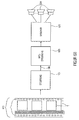
- Fig. 8 shows an exemplary film 110.
- Film information is applied to the film in spatial sequence, or during playback, respectively, in chronological order, for example video information or images 112, which are also referred to in English as “frames” or “video frames” and audio information or one or a plurality of analog or digital audio tracks 114, which in the digital case have "audio frames”.
- the film 110 has, by way of example, feed perforations 116 with the aid of which the film is played.
- the first method involves the storage of a time code on the data carrier, such as DTS (Digital Theater System) for Kinoton, or in an additional channel, which is connected to the audio signal.
- DTS Digital Theater System
- Examples are ancillary data by DAB and mp3.
- the time code is then used to play audio or additional information synchronously from an external data carrier, for example CD in DTS.
- Proprietary formats prevent the use of timecode extension by other extensions. Mutual disturbances of the extensions are not always preventable, an example of this is the use of ancillary data in mp3 for additional information and bandwidth expansion of various manufacturers.
- the second method is based on the misuse of analog audio tracks for storing time code as described e.g. in a prototype cinema equipped with an IOSONO system.
- a disadvantage of this method is that the analog track is present in all systems and is often used as a fallback solution in case of disturbances of the other systems, that is, an alienation of the analog track prevents the fallback option.
- the automatic switching to the analogue track which is installed in most cinemas, causes the timecode to be played back as an analog signal if no signal is present on the "more modern" Dolby Digital or DTS tracks.
- the redundant analogue reproduction must be switched off manually in the case of pure wave-field synthesis reproduction, which will be explained below, because otherwise the timecode can be heard via the redundant further loudspeakers.
- WFS Acoustic Wave Field Synthesis
- the WFS tries to reproduce the air vibrations of a real situation, which make up the sound, over a whole room.
- the wave field synthesis is to faithfully transfer the entire sound field to the room. This means that the virtual sound sources can be exactly spatially localized, and possibly even seem to exist in the middle of the sounded room, thus they can be bypassed.
- Systems with up to 200 loudspeakers in cinema systems and up to 900 loudspeakers in theater sound systems have already been realized.
- Wave field synthesis is based on Huygens' principle, which states that any point on a wavefront can be considered the starting point for an elementary spherical wave. By interference of all elementary waves, a new wavefront arises, which is identical to the original wave.
- the cinema Ilmenau in which the wave field synthesis is operated in two modes.
- the cinema is operated as a "real" wave field synthesis system, where the analog track of the 35 mm film stores the time code, as explained previously with regard to the second "abusive" method, and the WFS sound from an external one Medium, eg Hard disk or DVD, is leaked.
- the analog track of the 35 mm film stores the time code, as explained previously with regard to the second "abusive" method, and the WFS sound from an external one Medium, eg Hard disk or DVD, is leaked.
- the sound stored on each 35 mm film is read out and decoded by a Dolby processor, alternatively DTS or SDDS could also be used, the Dolby processor If necessary, automatically switches to the analog track, and maps the resulting multi-channel signal via WFS on virtual speakers.
- a Dolby processor alternatively DTS or SDDS could also be used, the Dolby processor If necessary, automatically switches to the analog track, and maps the resulting multi-channel signal via WFS on virtual speakers.
- a major disadvantage of the prior art described above is that the comparison between the stored audio signal and the audio signal sampled by the film is limited to a window of, for example, one minute in length. If the portion of the sound signal currently being scanned by the film is not in the range of the window of the stored sound signal, the search for a location in the film is unsuccessful or leads to a determination of a wrong location and thus to a false synchronization. In this case, the cinema audience hears the wrong sound to the picture.
- the object of the present invention is to provide an efficient concept for determining a location in a film.
- the present invention is based on the finding that a two-step approach, in which an approximate location in a film is first determined in a lower scan rate search window, and then based on this roughly determined location, accurately determines the location in the film With the second window being shorter and being scanned at a higher sampling rate, a faster and more efficient determination of a location in a film is made possible than the prior art described above.
- a method of detecting a location in a film comprising: a memory for storing film information deposited on a film in temporal succession, the stored film information being associated with a time scale, means for receiving one of A read portion of the film, and a synchronizer configured to compare a sequence of samples of the read portion on which a first sampling rate is based and a first search window of the stored film information to obtain a coarse result, and a sequence of samples of the in order to obtain a fine result indicative of the location of the film, wherein a position of the second search window in the stored movie information is different from the coarse result is dependent, wherein the first search window is longer in time than the second search window and wherein the first sampling rate is lower than the second sampling rate.
- the synchronization means is adapted to compare a sequence of samples of a read portion by correlation with a search window of the stored movie information.
- the synchronization means is adapted to compare the sequence of samples of the read portion underlying a first sample rate with a plurality of versions of the first search window, each version of the first search window being based on a different sample rate Coarse result, eg a more pronounced peak than the correlation result, and a sequence of samples of the read portion on which a second sampling rate is based, with a plurality of Compare versions of the second search window, each version of the second search window is based on a different sampling rate to obtain an accurate fine result for the determination of the location in the film.
- the device and the method for determining a position in a film can, for example, be used in a device for generating a control signal for a film event system that synchronizes film events with a picture display.
- Examples of movie events are audio sound, subtitles and special effects, where special effects e.g. Air currents, jiggling on the cinema chairs, odors or lighting effects on the side and rear wall may include.
- special effects e.g. Air currents, jiggling on the cinema chairs, odors or lighting effects on the side and rear wall may include.
- both different languages e.g. simultaneous playback of the original version and translations into other languages, as well as various audio techniques possible, such as the synchronization of digital surround systems such as wave field synthesis.
- the invention is not limited to movies for a moviegoer, but generally refers to movies or audio-video signals, whether or not they are This is about film or other media and storage media, such as magnetic tapes or hard drives, stored movie information is.
- the invention can also be used for pure sound systems without video or for example by means of a video ID synonymous for synchronization of pure video material, ie without sound, can be used with any event.
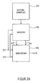
- FIG. 12 shows a basic block diagram of a device for generating a control signal for a film event system and an exemplary film 110, as described above with respect to FIG. Fig. 8 has been explained, wherein the means for generating a control signal, a means for storing 120 film information, a means for receiving a read from the film portion 140, a device 160 for comparing the read portion with the stored film information 112, 114 and means 180 for Determining the control signal based on the comparison and the time scale.
- the stored film information 112, 114 comprises, for example, the audio signals, the images or video signals or even marks which can already be found on films, and e.g. determine where the shutter will open or when the sound will be played or when the movie will stop.
- the stored audio and / or video signals are present, for example, in digitized form, preferably in compressed form, in order to reduce the memory requirement.
- One advantage of digitized storage lies in the simple and, above all, error-free duplication of the stored image of the film information.
- the film remains unchanged as previously described, producing only a stored image of the movie information once, e.g. in the production of the film.
- the audio signal contained on the audio track 114 is received by the receive device 140 and prepared for the compare device 160, for example, sampled at a given sample rate and as a portion of a given length or a given number of samples passed.
- the means 160 is adapted to compare this portion read from the film with the stored film information
- the means 160 for comparing may be arranged to compare the read portion with the entire stored film information, but preferably the read portion with a portion of the stored ones Film information compares to minimize the computational effort.
- the comparison can be done for example by cross-correlation, but also by calculating the difference, for example by calculating a compressed hash sum and search this in a database.
- the comparison may consist of the audio signal alone, the video signal alone, a comparison of the audio signal and the video signal and a combination with an evaluation of the aforementioned features.
- means 180 for determining determines control signal 190.
- Control signal 190 controls a film event system based on control signal 190 synchronized with the playback movie 110, for example, WFS audio signals Subtitles generated.
- the device for generating a control signal or in particular the means for determining the control signal 180 may be configured such that the control signal is any time code format, proprietary or standardized, such as the SMPTE (Society of Motion Picture and Television Engineers) standardized LTC (Longitudinal Time Code) time code format (LTC).
- SMPTE Society of Motion Picture and Television Engineers
- LTC Longitudinal Time Code
- Time-synchronized means that based on the control signal 190, the movie event system of one of the locations currently being played by the movie, which is assigned a time-on-scale time in the stored movie information, generates a concurrent event corresponding to that time scale.
- any film player may be used, any film formats, e.g. Silent films (eg, with video-based synchronization), analog or digital soundtrack, one or more parallel soundtrack, or any other storage media, such as cassettes or hard disks whose format can not be changed, or alternatively should, for example, continue to be compatible with the movie player, but at the same time other movie events should be synchronized.
- any film formats e.g. Silent films (eg, with video-based synchronization), analog or digital soundtrack, one or more parallel soundtrack, or any other storage media, such as cassettes or hard disks whose format can not be changed, or alternatively should, for example, continue to be compatible with the movie player, but at the same time other movie events should be synchronized.
- the audio signal is used as movie information for synchronization.
- the portion read from the film is scanned at a given sampling rate, hereinafter referred to as the test sampling rate, to produce a test tone signal and the stored movie information is stored in digital form, the stored film information being hereinafter referred to as the reference signal , and the test tone signal and reference tone signal are compared in the cross-correlation comparing means 160.
- the test signal sample rate and the reference signal sample rate are fixed, that is, constant.
- the means 160 for comparison may then be designed, for example, to generate a first correlation result at a first time on the basis of a first test tone signal and a first reference tone signal to determine a first time scale of the time scale, and at a second time a second test tone signal generating a second correlation result to a second reference sound signal to determine a second time scale of the time scale to determine therefrom, for example, a time difference or playback speed or to determine a speed difference as compared to a desired or reference playback speed.
- the means 180 for determining the control signal determines the control signal, for example, to synchronize the movie event system.
- a disadvantage of a constant sampling rate is that at a changing test playback speed, the correlation result deteriorates, and thus the accuracy of the determination of the time or the point in the film is inaccurate and thus the synchronization is worse.
- This disadvantage can be compensated by varying the sampling rates, ie the test sampling rate and / or the reference sampling rate.
- FIG. 12 shows a principle block diagram of an apparatus for performing a correlation between a test sound signal that is playable at a variable playback speed and a reference sound signal that is a digitally stored version of the test sound signal
- the apparatus for performing a correlation comprises means 210 for determining a measure of a test signal Test playback speed, means 230 for varying a test sample rate or reference sample rate, and means 250 for comparing.
- the device 230 is designed to provide a test sampling rate with the test sound signal 270 is sampled to vary to produce a modified test signal 272 or to vary a reference sample rate to produce a modified reference sound signal 276 based on a reference sound signal 274.
- the means 230 for varying is further configured to vary the test sampling rate or reference sampling rate such that a deviation between a test playback speed associated with the test sound signal or a reference playback speed associated with the modified reference sound signal 276 is reduced or a deviation between a test playback speed associated with the modified test sound signal 272 and a reference playback speed associated with the reference sound signal 274, or a deviation between a test playback speed associated with the modified test sound signal 272 and a reference playback speed associated with a modified reference sound signal 276 , wherein the term playback speed or the problem of a variable playback speed will be explained in more detail below.
- the means 250 for comparing the modified test sound signal 272 and the reference sound signal 274, or the test sound signal 270 and the modified reference sound signal 276, or the modified test sound signal 272 and the modified reference sound signal 276 is designed to determine a result 278 of the correlation.
- FIG. 2a For example, in an apparatus for generating a control signal for a movie event system, such as shown in FIG Fig. 1 is shown used as means 160 for comparison.
- Fig. 2b shows a schematic block diagram of a preferred embodiment of an apparatus for performing a correlation between a test sound signal and a reference sound signal.
- FIG. 11 shows means 280 for storing a reference sound signal 274 which is a digital version of the test sound signal 270, the reference sound signal 274 having been generated once based on a given memory reference playback speed and a memory reference sample rate.
- test tone signal is played back at a variable test playback speed and sampled at a test sample rate to produce the test tone signal 270.
- the test-play-speed measurement means 210 of the test sound signal 270 controls the means 230 for varying on the basis of the test-playback-speed measurement.
- the means 230 for varying in turn controls a reference rate converter 232 and a variable sampler 234, wherein the sample rate converter 232 is configured to convert from the reference audio signal based on the memory reference playback speed and a memory reference sampling rate into a modified reference sound signal 276 corresponding to a reference audio signal which is based on a different memory reference playback speed and / or memory reference sampling rate, and wherein the variable sampler 234 is adapted to sample the test sound signal at a different sampling rate, that is to say from the standard or basic sampling rate, to produce a modified test sound signal 272.
- the means for performing a correlation may also be such that the test sound signal 270 is always supplied via the variable sampler 234 to the means 250 for comparison, the variable sampler 234 then being arranged such that one of the standard or variable test sample rates Basic sampling rate, and further that the reference sound signal 274 is always supplied to the means 250 for comparison via the reference sampling rate converter 232, the reference sampling rate converter 232 being arranged to unmodify the reference sound signal 274 when appropriately driven by the means 230 for varying to the device 250 for comparison.
- Fig. 2b selected representation of the separate supply of the test sound signal 270 with respect to the modified test sound signal 272 and the reference sound signal compared to the modified reference sound signal 276 to the means 250 for comparison, serves to represent the alternative execution possibilities or realization possibilities.
- the means 250 for comparing is configured to compare the modified test sound signal 272 with the unmodified reference sound signal 274, no reference sample rate converter 232 is necessary or instructs the apparatus to perform correlation Fig. 2b no reference sample rate converter 232.
- a comparing means 250 configured to compare the unmodified test sound signal 270 with the modified reference sound signal 246 does not include a variable sampler 234.
- the means 280 for storing is a means for storing a movie information, wherein the stored movie information is associated with a time scale, and the test sound signal 270 is, for example, a movie sound signal.
- the device for performing a correlation according to Fig. 2b can then, for example, as means for comparing 160 according to Fig. 1 be used.
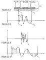
- FIG. 11 shows a portion of an exemplary film 110 having a soundtrack 114 as in FIG Fig. 1 previously described.
- two locations of the film 110 are plotted, a first location, hereinafter referred to as location L 1 , and a second location, hereinafter referred to as location L 2 .
- Fig. 2c.2 shows an exemplary course of the test sound signal that corresponds to the in Fig. 2c.1 is assigned to section described between the location L 1 and L 2, further comprising the time at which the position L 1 of the movie is played back is referred to as time T 1 and the time at which the position L 2 of the movie is playing, is referred to as time T 2 .
- T 2 - T 1 L 2 - L 1 / v ,
- n .DELTA.L / .delta.t ⁇ v respectively.
- n .DELTA.L ⁇ f / v . that is, the number of sampling periods or samples for a given film portion ⁇ L is proportional to Sampling rate f or antiproportional to the sampling period .DELTA.t and antiproportional to the playback speed v.
- the quotient "f / v" or the product " ⁇ t ⁇ v" must be constant if n or the number of samples n + 1 should be constant. If the first sample value is the same in this case, the individual samples are the same under the condition mentioned above.
- the stored portion of the movie information or the test sound signal is represented and stored by n memory + 1 reference samples, for example.
- Fig. 2c.2 to 2c.4 exemplary samples or storages of the film portion between the location L 1 and the location L 2 for a constant sampling rate f and a variable sampling rate ⁇ t and a variable playback speed, respectively
- Fig. 2.c2 shows an exemplary sample or storage for a first playback speed v 1
- Fig. 2c.3 shows a sample or storage of the same film section at a second playback speed v 2
- Fig. 2c.4 shows a scan of the same film section for a third scan speed v 3 .
- v 1 is half the size of v 2 and twice as large as v. 3
- Fig. 2c.2 to 2c.4 corresponds to a constant sampling rate
- an increase in the playback speed v of a temporal compression of the audio signal ie a doubling of the playback speed v 1 off Fig. 2c.2 leads as in Fig. 2c.3 represented to a halving of T 2 - T 1 and n
- a reduction of the playback speed v to a temporal extension of the audio signal ie a halving of the playback speed v 1 from Fig. 2c.2 leads as in Fig. 2c.4 represented to a doubling of T 2 -T 1 and n.
- the Fig. 2d.1 and 2d.2 essentially correspond to the Fig. 2c.1 and 2c.2 .
- time T 0 which represents the time associated with point L 0 based on a given playback speed
- time T 3 which represents the time associated with point L 3 based on a given playback speed
- T 0 defines, for example, the time on the time scale, which is assigned to the point L 0
- the time T 1 defines the time on the time scale
- the point L 1 defines the time on the time scale
- the time T 2 defines the point in time on the time scale defining point L 2
- time T 3 the time on the time scale associated with point L 3 on the film.
- Fig. 2d.3 equals to Fig. 2c.2 .
- Fig. 2d.3 a currently read one of the film applied to the film information or the test sound signal 270 and Fig. 2d.2 a stored film information or a reference sound signal, wherein in an optimal case, here by the Fig. 2d.2 and Fig. 2d.3 and the memory sampling rate at which the reference sound signal was generated coincides with the playback speed of the test sound signal and the sampling rate of the test sound signal.
- the quotient of memory sampling rate f memory and memory playback speed v stores the quotient of the sampling rate for the test sound signal f and the playback speed of the test sound signal v coincide.
- the reference sound signal or a portion of the reference sound signal which is defined by T 1 and T 2
- the test sound signal representing the portion between T 1 and T 2
- correlation clear local maximum or a correlation peak are obtained, as exemplified in Fig. 2d.4 is shown.
- the position of the peak in turn indicates the time shift of the test sound signal relative to the reference sound signal or the search window. Based on this, the current time with respect to the stored time scale can then be determined.
- the Fig. 2d.5 to 2d.8 show in contrast to the Fig. 2d.1 to 2d.4 an example in which the playback speed of the test sound signal, shown in Fig. 2d.7 compared to the playback speed of the test sound signal, as in Fig. 2d.2 is shown reduced.
- FIG. 10 illustrates an example trace of a reference tone signal based on a memory sample rate f memory and a memory playback speed v memory .
- Fig. 2d.7 shows an exemplary course or exemplary sampling of the test sound signal, based on a comparison with 2d.3 or Fig. 2d.6 unchanged test sampling rate f, however, a changed, reduced playback speed v 'of the test sound signal.
- this means that in the same time interval ⁇ T at a reduced speed v 'only a lesser portion or a portion of lesser length ⁇ L' according to ⁇ L ' v' ⁇ ⁇ T is played back by the film is reached on the currently playing film after the period .DELTA.T only one point L ' 2 , which lies before the point L 2 , as shown in Fig. 2d.5 is shown. Relative to the reference sound signal and the time scale associated therewith, the point L ' 2 is assigned the time T' 2 of the timescale, as shown in FIG Fig. 2d.7 will be shown.
- the result of the comparison will be degraded, since, even under otherwise optimal conditions, the test sound signal and the reference sound signal represent two different spatial sections of the film.
- the result of the comparison becomes worse the greater the deviation of the memory playback speed from the test playback speed deviates.
- the magnitude of the local maximum or peak decreases and the maximum itself becomes wider and flatter, for example, so that the time determination with respect to the time scale becomes increasingly inaccurate until it is no longer possible.
- the playback speed of the test tone signal will not only vary between different movie players, but may vary during a movie. Accurate tracking is essential to ensure synchrony throughout an entire movie.
- the device for performing a correlation therefore varies the sampling rate of the test sound signal or the sampling rate of the reference sound signal in order to detect the adverse effect of a variable speed of the test sound signal, as described above, according to the above-described condition, the quotient of the sampling rate and the playback speed of the test sound signal and of the reference sound signal must be equal in order to represent the same film section with the same sampling values.
- the change in playback speed is effected by sample rate conversion, whereby the stored reference sound signal 274 is appropriately interpolated, for example, to generate a reference sound signal at the sampling rate corresponding to the changed playback speed.
- Fig. 2d.1 - 2d.8 illustrate simplified examples in which, for the sake of clarity, it has been assumed that the memory playback speed v memory corresponds to a normal or standard playback speed of a playback device for generating a test sound signal.
- the quotient of sample rate f and playback speed v is the magnitude that must be the same for the reference sound signal and the test sound signal to represent the same portion of the film with the same samples as previously indicated.
- a double playback speed can also be used if the sampling rate is simultaneously doubled.
- the means 210 for determining may determine a measure of a test playing speed based on the result 278 of the correlation.
- One possibility is to use a single correlation result for the determination of a measure of the playback speed, for example, by comparing an amplitude of a peak with a predetermined threshold to determine whether a deviation between a playback speed of a test sound signal and a reference sound signal is within a predetermined range.
- At least two different reference sound signals which are based on different reference sampling rates and / or different reference playback speeds, are compared with the test sound signal to obtain the results of the correlation, for example by means of a quality assessment relating to Fig. 5 will be explained in more detail in order to determine from these a most similar Referenztonsignal and thus based on the known sampling rate and the known memory playback speed, a measure of the playback speed of the test sound signal.
- the different reference sound signals can be formed one after the other and compared with the test sound signal or simultaneously formed and compared.
- a particularly preferred embodiment of the apparatus for performing a correlation generates three reference sound signals based on different reference sampling rates, wherein the reference sound signal of the middle of the three sampling rates is based on the reference sampling rate of the reference sound signal which in a previous comparison is the best quality or maximum match with the test sound signal and the two other reference sound signals each have a reference sampling rate higher or lower than the reference sampling rate of the middle reference sound signal.
- This is controlled by the means 230 for varying on the basis of an output of the means 210 for determining the measure of the test playing speed. This ensures that the reference sampling rate or the reference playback speed of the reference sound signal is matched to the playback speed or reference sampling rate of the test sound signal.
- Fig. 3a shows an exemplary movie, as in Fig. 8 and a basic block diagram of a device for determining a location in the film.
- an exemplary embodiment of the device for detecting a position in a film can be used in a device for generating a control signal for a film event system, as described, for example, in US Pat Fig. 1 is shown used as means 180 for determining the control signal.
- the device for determining a location in a film has a memory 320 for storing a reference fingerprint representation of the film information, wherein the fingerprint representation is designed so that a time profile of the fingerprint representation depends on a time profile of the film information, and wherein a stored reference fingerprint representation is assigned a time scale , means 340 for receiving a portion read from the film, means 350 for extracting a test fingerprint representation from the read portion, and means 36 for comparing the test fingerprint representation with the reference fingerprint representation to determine the location based on the comparison and the timescale to determine in the movie.
- the fingerprint representation comprises a representation in the form of a spectral flatness, wherein a time profile of the fingerprint representation comprises a time profile of the spectral flatness.
- Fig. 3b.1 shows an exemplary film 110 as in FIG Fig. 8 shown.
- a fingerprint is determined for particular spatial and temporal portions of the film.
- FIG. 16 shows a first portion including the portion from the location L 100 to L 113 and T 100 to T 113 , respectively, and a second portion including the portion from the location L 103 to the location L 116 and from the time T 103 up to the time T 116 includes. Based on these sections, a fingerprint associated with this section is generated based on, for example, spectral analysis, Fourier transformation, or other feature extraction methods.
- the fingerprint comprises the spectral flatness ⁇ x 2 , which is calculated from the course of the power density spectrum, so that the value of the spectral flatness is determined for each section, and depending on the time course of the film information, for example Sound signal, a sequence of spectral flatness, which are stored in the memory 320 with the associated time scale.
- Sampling rate, length or duration of the section, or the distance between two consecutive sections are determined according to the requirements for, for example, uniqueness or accuracy of determining the location in the film.
- the longer the section the clearer the feature's feature in general, the higher the sampling rate and / or the smaller the distance between two sections, the more accurately the location in the movie can be determined.
- the higher the sampling rate the longer the sections and the smaller the distances between the sections, the higher the memory requirement for the reference signal or the request for the computing power during signal processing.
- a significant advantage of the fingerprint representation in the form of the spectral flatness is its small memory requirement compared to, for example, a complete storage of the power density spectrum for a same section.
- a trace of spectral flatness is used as a fingerprint for a portion.
- Fig. 4 shows an exemplary film 110 as in FIG Fig. 8 and an apparatus for detecting a location in a film having film information applied in a temporal sequence.
- an exemplary embodiment of the device for detecting a position in a film can be used in a device for generating a control signal for a film event system, as described, for example, in US Pat Fig. 1 is shown used as means 180 for determining the control signal.
- the means for determining a location includes a memory 420 for storing film information deposited on a film in sequence, with a time scale associated with the stored movie information, means 440 for receiving a portion read from the film, and synchronization means 460 configured to compare a sequence of samples of the read portion underlying a first sampling rate and a first search window of the stored movie information to obtain a coarse result, and a sequence of samples of the read portion having a second sampling rate, and comparing a second search window of the stored movie information to obtain a fine result indicative of the location of the movie, wherein a position of the second search window in the stored movie information depends on the coarse result, and wherein the first search window is longer in time than the second search window, and further wherein the first scan rate is lower than the second scan rate.
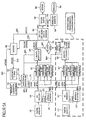
- Fig. 5a shows an exemplary film 110 as in FIG Fig. 8 and a preferred embodiment of a device for generating a control signal for a film event system, which is formed on the basis of an applied on the film analog audio track a read portion of the audio signal or test tone signal and a stored digital version of the test tone signal hereinafter referred to as Referenztonsignal, which is associated with a time scale, to determine by comparing the test sound signal and the reference sound signal by means of the time scale, the control signal.
- Referenztonsignal which is associated with a time scale
- An input of the first means 562 for correlation, an input of a second means 564 for correlation, and an input of the third means 566 for correlation are coupled to an output of a sample rate converter 232, referred to as a sample rate converter (SRC). connected.
- SRC sample rate converter
- An output of the first means 562 for correlation, an output of the second means 564 for correlation and an output of the third means 566 for correlation are connected to an input of a first means 568 for quality assessment.
- the quality assessment means 568 is coupled to the sample rate converter 232 and to a sampler selection means 570, an output of the sampler selection means 570 being connected to an input of a timer 582.
- the timer 582 in turn is connected to the stored soundtrack 522 for storing the soundtrack, wherein an output of the soundtrack storing means 522 is connected to an input of the sample rate converter 232.
- An output of the first feature extractor 552 is connected to an input of a feature comparison device 554 having, for example, a feature classifier and a database of features, an output of the feature comparison device 554 having an input of the timer 582 is connected.
- a feature comparison device 554 having, for example, a feature classifier and a database of features
- An output of the timer 582 is coupled to an input of a time code generation means 584 having a time code database or coupled to a time code database, and an output of the time code generation means 584 is connected to an input of a time code slicer 586, the means 586 is adapted for time code smoothing to output a time code 592, and further wherein an output of the time code smoothing means 586 is connected to an input of a word clock generator 588, which in turn is adapted to output a word clock signal 594.
- the apparatus for generating a control signal for a film event system optionally further comprises a second film tone sampler 542 'associated with a second A / D converter 544 ', the second A / D converter 544' having a second feature extractor 552 ', a fourth means 562' for correlation with a fourth reference sound signal based on the first sampling rate, a fifth means 564 'for a correlation with a fifth reference sound signal based on the second sampling rate and a sixth means 566 'for correlation with a sixth reference sound signal connected at the third sampling rate.
- An output of the fourth means 562 'for correlation, an output of the fifth means 564' for a correlation and an output of the sixth means 566 'for a correlation are connected to an input of a second means 568' for quality evaluation, wherein an output of the second Further, means 568 'for quality evaluation is connected to an offset compensation 569 and another output is connected to an input of the sample rate converter 232, and further wherein the means for offset compensation 569 is connected to the sample selection 570.
- the first film tone sampler 542 also referred to as a main sampler, is positioned so that there is enough time for the device to generate a control signal to lock itself up.
- the first film tone sampler 542 thus provides a pre-delayed signal.
- At Aufsynchronisationszeit still adds the correlation window width or width of the portion of the test sound signal.
- the time difference for the pre-delay can be set exactly. As a first clue, three seconds is recommended.
- the first film tone sampler 542 reads the sound signal from the soundtrack of the film, and samples the sound signal from the soundtrack of the film, and passes this signal to the first A / D converter 544, where the first A / D converter 544 is formed to generate a digital audio signal or test tone signal based on the sampling rate of the first film tone sampler 542 and the playback speed of the film from which the audio track or movie information is being read.
- test fingerprint representation On the basis of the test sound signal 270, one or a plurality of features is extracted or a test fingerprint representation is formed. For example, the spectral flatness is used as a characteristic or fingerprint for the feature extraction or fingerprint representation.
- the test fingerprint representation is then compared by the feature comparison device 554 with a reference fingerprint representation, as previously noted, wherein the fingerprint representation is such that a time history of the fingerprint representation depends on a temporal history of the movie information, and where a A reference fingerprint representation stored in feature 554 is associated with a time scale, and means 554 for comparing is adapted to determine a location in the film based on the comparison of the test fingerprint representation with the reference fingerprint representation and the time scale respectively a time code signal 554Z produce.
- the sampling rate converter easily generates the same signal based on the stored reference sound signal 274 different sampling rates, ie modified reference tone signals, for the correlations to be calculated in parallel.
- modified reference tone signals the case where a modified reference sound signal has the same sampling rate as the original reference sound signal is included herein, so that the discussion of the Fig. 5 Furthermore, the term reference tone signals is generally used.
- sampling rate converter 232 generates three reference sound signals 276 and modified reference sound signals 276, respectively, wherein a first reference sound signal is based on a first sampling rate and supplied to first means 562 for correlation, wherein a second reference sound signal 276 is based on a second sampling rate and the second means 564 for correlation, and a third reference sound signal 276 based on a third sampling rate and supplied to a third means 566 for correlation.
- the sample rate converter 232 provides low-level, sample rate-different signals to the correlation device 562, 564, 566, respectively, with the sample rate always set in correlation with the previous measured maximum peak-to-noise value from the correlation becomes.
- a correlation gets a modified reference sound signal with this sampling rate
- another correlation gets a little lower, one level lower, and another correlation gets a slightly higher graduated sampling rate. This ensures that the sample rate converter can, for example, tune or synchronize to a change in the speed of the analog audio signal.
- the means 522 for storing the soundtrack and the sampling rate converter 232 are preferably designed to use a window width of 2 n, in order to calculate low-cost large correlation windows by means of the fast Fourier transformation (FFT). There may be more than three correlations in parallel be calculated to compensate for sudden jumps in the soundtrack.
- the correlation window is chosen to be large in order to obtain a clear correlation peak. In order to obtain the recognition accuracy of the correlation peak under a sample or a sampling period, it is possible to work with oversampling of the input signal or test tone signal.
- the sound track storing means 522 outputs the reference sound signal in the length of the correlation window depending on the supplied time code signal 582Z of the timer 582, the correlation window being the search window in which the test sound signal is searched.
- the first quality judging means 568 is configured to perform a maximum value search in the cross-correlated ones of the signals and the amounts of the cross-correlates, depending on the height of the correlation peak compared to other peaks in the cross-correlated one the peak-to-noise distance to determine the quality of each individual correlation.
- the best quality reference tone is determined and the displacement of the peak from the search window is determined based on the position of the peak of the best quality reference tone, for example as a time code difference between the measured and currently valid time code or relative time code issued.
- the first quality judging means 568 sends a control signal 568A to the sampling rate converter 232, which for example distinguishes only the three signal values "0", “+1” and "-1", for example at “0" the sampling rates the last sample rate conversion or correlation, because the correlation result from the modified Reference tone signal with the average sampling rate was determined to be the highest quality, at "+1” the sampling rates are increased by one step compared to the last sampling rate conversion or correlation, because the correlation result from the modified reference tone signal with the highest sampling rate was determined to be the highest quality, and at "-1" the sampling rates are reduced by one step over the previous sample rate conversion since the correlation of the test tone signal and the modified reference tone signal with the lowest reference sample rate had the best correlation-to-peak-to-noise ratio ,
- the sample rate converter will be e.g. is increased or decreased by one sample rate delta value, or so driven that it does not sample rate conversion.
- the correlation serves to address two important aspects. First, determining the location in the film or determining the point in time in the film on the basis of the time code difference from the correlation. Second, determining the measure of the playback speed to determine the optimum reference sample rate or sample rate conversion of the reference sample rate, respectively.
- the adaptation of the sampling rates or the recapture of adapted playback speeds in turn enables better correlation results and thus in turn improves the timing or determination of the location in the film and thus in turn improves the synchronization and the prediction.
- a preferred embodiment according to Fig. 5 is designed, by means of a signal analysis, to detect signal parts with specific characteristics in order to then hide them during synchronization and thus false detections or to prevent synchronization or to avoid random fluctuations of the time axis.
- Such characteristics can be, for example, the loudness of the signal part or the "problem" of a signal and the signal analysis or detection of problematic parts on the basis of SNR (Signal to Noise Ratio), PNR (Peak to Noise), Spectral power or line density spectral, spectral flatness, or averaging a time series.
- SNR Signal to Noise Ratio
- PNR Peak to Noise
- Spectral power or line density spectral spectral flatness
- spectral flatness or averaging a time series.
- the time code difference can be recognized as invalid. Or, for example, if multiple peaks with similar peak-to-noise ratios are detected, the time code difference may also be identified as invalid.
- the quality of correlations with quiet signal portions is lower than correlations with loud signals because of the higher quantization noise in the digital sample, therefore, quiet signal portions are thresholded or adaptively masked to coincidental ones To avoid fluctuations in the time axis.
- the signal energy can be another quality feature.
- Another example is the hiding of problematic, because recurrent signal parts to avoid ambiguity and thus, for example, incorrect synchronization.
- Problematic signal parts or sections can also be signaled as metadata, for example, in order to hide these signal parts, regardless of the quality of the current correlation.
- the time code generation means 584 is designed to convert based on the time code signal 582Z of the timer 582, which may for example be based on an internal or proprietary time code, into a standardized time code or a time code signal based on a standardized time code, for example.
- the timer 582 is controlled by an internal clock (frequency of correlations), a coarse audio ID fingerprint, such as the time code signal 554Z from the feature determination, and the detected correlation difference, such as from the correlation determined time code difference signal 570Z of the device 570 for scanner selection.
- the timer must prioritize correlation signal (highest priority), time code from feature determination, and internal clock (lowest priority).
- the time code smoothing means 586 is arranged to smooth the time code signal 584Z so as to avoid, for example, a hopping time code or, if there are time codes from the correlation, to find meaningful intermediate values, e.g. Compensate for pauses in the analog tone.
- the time code signal 592 generated by the time code slicer 586 is preferably a standard time code with which the movie event system is synchronized. However, the time code signal 592 may also be used to generate a corresponding sample clock or sample clock via a very slowly regulating phase locked loop (PLL) if the included audio reproduction system is digital. Such phase locked loops are available as finished devices and are not the subject of this patent.
- PLL phase locked loop
- more than one telecine with time-varying offset from the projection lens can improve the robustness of film damage or synchronization poorly suited sections are used.
- a second film tone sampler 542 ' may then be used, for example, since the second film tone sampler 542' is already present in conventional cinema systems. Breaks in the analog tone can hereby be bridged by the film tone samplers 542, 542 'attached at different locations on the motion picture film, since the probability increases with short pauses in the film sound, the at least one scanner, the first film sound scanner 542 or the second film sound scanner 542', enough signal for a correlation and the associated synchronization provides.
- different scanners e.g. for analog sound, Dolby Digital sound (including decoder), DTS digital sound (including DTS decoder) or another sound, and a combination of the above may be used as the reference soundtrack and / or test soundtrack.
- individual traces can be used for comparison using averaging, majority decision or prioritization, automatically or via metadata, the time information generated therefrom, as well as a downmix to mono.
- different scanners may be used for different audio formats and / or different film scanners with different timing offsets.
- Using a downmix on mono has the advantage that when the monaural track is used as a stored audio track, it saves less than storing five channels, for example.
- the storage of different, ie more than one soundtrack, ie no downmix means that all channels are stored independently of each other and then, for example, as previously explained, making corresponding majority decisions to then perform the synchronization using a particular channel, the actual soundtrack, and a corresponding channel of the stored soundtrack.
- the initialization phase or the first synchronization and the resynchronization after a recording pause form two critical phases during a film projection or a synchronization of a film event system.
- preferred embodiments initially calculate more than three parallel correlations since no synchronization has yet occurred, that is, more than three reference tone signals of different sample rates are compared with the test tone signal to determine the correct sample rate or playback speed of the test tone signal as quickly as possible.
- the first feature extractor 552 and the feature classification means 554 in combination with the database provide a coarse absolute time code value defining a coarse location in the film to determine, in a second step, for example, by the correlation, a fine determination of the location of the film or film to perform a fine time code determination.
- a second step for example, by the correlation, a fine determination of the location of the film or film to perform a fine time code determination.
- a point in a movie or point assigned to the point can be assigned on a time scale depends on the sampling rate of the reference sound signal and the sampling rate of the test sound signal, the higher the sampling rate, the more accurate the location in the film can be determined.
- a lower sampling rate has the advantage that with the same number of samples, a longer portion of the reference sound signal or the test sound signal can be represented.
- a rough determination of a location in a film is to be made by displaying a longer portion of the film by a reference sampling signal at a lower sampling rate, and also obtaining a test tone signal by sampling at a lower sampling rate.
- a higher sample rate reference tone signal and a higher sample rate test tone signal are used to finely determine the location in the film.
- the window length is adjusted when correlated.
- time-long windows but a reduced sampling rate of the signals are used, if a time is about to be found and only tracked, short windows may even be used with oversampling of the signals to achieve higher temporal accuracy.
- a "compatible reproduction” of the "old" audio format can take place until the exact position is determined.
- a "compatible" playback of the "old” audio format can be done if the synchronization has been significantly lost until the exact position is determined again.
- the scanner selection means 570 and the offset compensation means 569 are necessary only in embodiments with more than one film sound scanner.
- the means 570 for selecting the scanner decides whether the result or time code difference of the first quality assessment means 568 (568Z) or the result or time code difference 568Z 'of the second quality assessment means 568' is passed on to the timer 582 for determining a location in the film and a time code 582Z, respectively.
- the different reference sound signals of different reference sampling rates can also be generated successively and compared with the test sound signal to determine the measure of the playback speed of the test sound signal and the optimum reference sampling rate, respectively.
- more than three modified reference sound signals may be compared to the test sound signal, in parallel or serially, to enable fast synchronization not only in the initial phase, but also during movie screening, the film event system for larger cracks in the film, eg by cuts or in film missing sections causes faster sync to the current spot in the movie.
- a synchronization of a film event system can also take place on the basis of the images applied to the film, both for an evaluation of features or fingerprints and for a correlation of a test image signal with one or a plurality of reference picture signals.
- the correlation of audio and / or video signals for determining the temporal location in an audio and / or video stream can be used, and a synchronous playback can be controlled on the basis of this timing.
- the determination of an audio and / or video signature from the raw material in the form of an audio ID / video ID (ID) for roughly determining the time in a long AV stream may also be used to synchronize to allow any position.
- ID an audio ID / video ID
- the basic approach of the invention is, for example, to digitally store the already existing analog tone, in order then to synchronize it to the motion picture film by means of correlation and other feature determination with the analog sound track.
- the output signal or control signal of the device for generating a control signal or of the synchronizing device can be any time code format.
- a data set for the device for generating a control signal or for the synchronization device must be created during production.
- the data carrier includes the digitized analog audio track, e.g. in dolby stereo format as found on the roll of film, feature data about the soundtrack and matching timecodes.
- Fig. 5b.1 shows an exemplary film 110 with a soundtrack 114, as already in FIG Fig. 8 described.
- a reference sound signal 274 is read from the means 522 for storing an audio track, and a modified reference sound signal is read out by means of the sample rate converter 232 Fig. 5b.2 generated, the associated time 0 represents a film portion of the spot L 0 to the position L 3 or the site of the L 0 T or a corresponding time code and the location L 3 assigned time T 3 and time code.
- Fig. 5b.4 shows the result of the correlation of the modified reference sound signal according to Fig. 5b.2 and the portion of the test tone signal Fig. 5b.3
- the quality assessment 568 it is not necessary for the quality assessment 568, the knowledge of the absolute time T 0 or the time T 1 , since, for example, the timer 582 the last absolute Time or absolute time code and only the time code difference 570Z needed to determine the updated absolute time or time code.
- the difference can be represented, for example, from the position of the peak with respect to the time of the beginning of the search window.
- the peak is the fourth sample, ie, the test tone signal Fig. 5b.3 is off by "3 ⁇ ⁇ t" from the reference sound signal Fig. 5b.2 where ⁇ t is the sampling period corresponding to the modified sampling rate.
- the advantage of the adapted to the variable playback speed of the test sound signal sampling rate or playback speed of the reference sound signal advantageous to wear, since the .DELTA.t is adapted to the playback speed, a more accurate determination of the location in the film or displacement relative to the search window is possible than at a fixed sampling rate of the reference sound signal, since then only multiples of this sampling rate are generated for a determination of the location in the film.
- the time T 0 of the search window or reference sound signal can be equal to the T 1 of the previous correlation, since the film is played only forward.
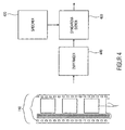
- FIG. 12 shows an embodiment of a movie system in which a device 100 for generating a control signal 190 is coupled to a movie event system 600, thereby generating the device 100 for generating a control signal based on the movie 110 as in FIG Fig. 8
- the control signal 190 for example a time code, is synchronized with the movie event system 600.
- FIG. 3 shows a film system having a device 100 for generating a control signal 100 and a wave field synthesis system 610 as an exemplary film event system, wherein the embodiment of the wave field synthesis system 610 comprises means 620 for controlling the wave field synthesis system, a digital memory 622 for the wave field synthesis audio signals, and a plurality of loud speakers 624 for the wave field synthesis system.
- the control signal generating device 100 Based on the film 110 or, for example, an analog movie soundtrack 114, the control signal generating device 100 generates the control signal 190 to lip-sync a wave analog audio audio experience to an originally analog-converted movie.
- wave field synthesis system 610 can of course also be synchronized lip-synchronously by means of the device 100 for generating a control signal.
- other audio systems for example digital audio systems or digital surround audio systems, can of course also be synchronized lip-synchronously by means of the device 100 for generating a control signal.
- Fig. 7 shows an exemplary movie, as in Fig. 8 an exemplary digitally stored reference sound signal 720 and a time scale assignment.
- the analog audio signal is sampled at a given playback speed and rate, for example, 44.1 kHz, and audio portions of, for example, 10 ms are stored as a so-called audio frame, that is, the digital reference sound signal is present on the memory as a result of audio frames.
- the assigned time of a time scale can then consist, for example, of numbering the audio frames from 0 or 1 in ascending order as the time code or time scale.
- Time code TC1 corresponds to audio frame AF1 in FIG Fig. 7 or, for example, to find the start time or end time of an audio frame as the time code, eg, for the first audio frame, either 0 ms or 10 ms if an audio frame has a duration of 10 ms.
- Timecodes usually have formats such as hour: minute: second: frame, whereby the frame is more commonly used refers to video frames with eg 24 frames per second (movie).
- a time scale or time code can therefore, for example, assign a plurality of audio frames to a video frame or define an audio frame as the smallest time scale unit. Accordingly, the time code or the time scale then, for example, 4 audio frames assign a time code, see TC1 'in Fig. 7 comprising four audio frames AF1 -AF4 or assigning a single Audi frame to a time code, see TC1 in FIG Fig. 7 to which an audio frame AF1 is assigned.
- the audio frames may also represent temporally overlapping sections of the audio signal.
- the control signal 190 may be formed, for example, as a time code, but also as a sequence of pulses, wherein, for example, each pulse corresponds to a time scale unit and similar to a relative time code, the film event system accumulates the pulses to synchronize with the film.
- a further exemplary embodiment in order, furthermore, to have available, for example, an analog audio signal as a fallback, but at the same time also to realize a time code for synchronous additional services, offers the approach of embedding a watermark in the audio and / or video signal.
- Advantage of this solution is that even with "difficult" audio signals, such as very quiet passages or even similar "monotonous" noises, a clean clock recovery is possible.
- the complete set of the relevant Watermark claims in particular in the field of searching for the correct clock rate or the readjustment of the sampling rate, makes sense for this variant.
- the decisive disadvantage of this approach is that the actual film must be changed or a new version or copy of the film must be created in order to embed the Watermarks in the audio and / or video signal can.
- the method according to the invention can be implemented in hardware or in software.
- the implementation may be on a digital storage medium, in particular a floppy disk or CD with electronically readable control signals, which may interact with a programmable computer system such that the method is performed.
- the invention thus also consists in a computer program product with a program code stored on a machine-readable carrier for carrying out the method according to the invention, when the computer program product runs on a computer.
- the invention can thus be realized as a computer program with a program code for carrying out the method when the computer program runs on a computer.
Description
Die vorliegende Erfindung bezieht sich auf eine Vorrichtung und ein Verfahren zum Ermitteln einer Stelle in einem Film, um beispielsweise Filmereignisse mit einer Bildwiedergabe zu synchronisieren.The present invention relates to an apparatus and method for determining a location in a movie, for example, to synchronize movie events with a picture display.
Audio-Video-Daten sind auf Datenträgern, z.B. Film oder Band, oder Übertragungskanälen, z.B. Rundfunk oder Telefon, in einem festen Format gespeichert, welches eine Erweiterung um neuartige Audioformate oder andere synchrone bzw. bildsynchrone Zusatzdienste, wie z.B. Untertitel, nicht zulässt. Bei der Einführung beispielsweise neuer Audioformate müssen daher neue Datenträger bzw. Filmkopien produziert werden, die die neuen Audioformate aufweisen.Audio-video data is on data carriers, e.g. Film or tape, or transmission channels, e.g. Radio or telephone, stored in a fixed format, which can be extended to include new audio formats or other synchronous additional services, such as Subtitles, does not allow. For example, when new audio formats are introduced, new media or movie copies must be produced that have the new audio formats.
Zur Synchronisation von Zusätzen sind prinzipiell zwei Methoden bekannt.For the synchronization of additives, two methods are known in principle.
Die erste Methode beinhaltet das Speichern eines Timecodes auf dem Datenträger, wie z.B. bei DTS (DTS = Digital Theatre System) für Kinoton, bzw. in einem Zusatzkanal, der mit dem Audiosignal verbunden ist. Beispiele hierfür sind ancillary data by DAB und mp3. Der Timecode wird dann verwendet, um Ton- bzw. Zusatzinformationen synchron von einem externen Datenträger, bei DTS z.B. CD, abzuspielen. Nachteilig an dieser Methode ist jedoch, dass jedes zusätzliche Format weiteren Platz auf dem Datenträger bzw. Übertragungskanal benötigt, der unter Umständen aber nicht mehr verfügbar ist. Beim Film sind dies z.B. die Spuren für Analog-Ton, Dolby-Digital, DTS, SDDS (SDDS = Sony Dynamic Digital Sound). Proprietäre Formate verhindern jedoch die Nutzung des Timecodes einer Erweiterung durch andere Erweiterungen. Gegenseitige Störungen der Erweiterungen sind nicht immer zu verhindern, ein Beispiel hierfür ist die Nutzung von ancillary data in mp3 für Zusatzinformationen und Bandbreitenerweiterung verschiedener Hersteller.The first method involves the storage of a time code on the data carrier, such as DTS (Digital Theater System) for Kinoton, or in an additional channel, which is connected to the audio signal. Examples are ancillary data by DAB and mp3. The time code is then used to play audio or additional information synchronously from an external data carrier, for example CD in DTS. The disadvantage of this method, however, is that each additional format requires more space on the disk or transmission channel, which may not be available anymore. In the case of film, these are, for example, the tracks for analogue sound, Dolby Digital, DTS, SDDS (SDDS = Sony Dynamic Digital Sound). Proprietary formats, however, prevent the use of timecode extension by other extensions. Mutual disturbances of the extensions are not always preventable, an example of this is the use of ancillary data in mp3 for additional information and bandwidth expansion of various manufacturers.
Die zweite Methode basiert auf der missbräuchlichen Benutzung von Analog-Ton-Spuren zur Speicherung von Timecode, wie sie z.B. in einem Prototypenkino, das mit einem IOSONO-System ausgestattet ist, verwendet wird. Nachteilig an dieser Methode ist jedoch, dass die Analogspur in allen Systemen vorhanden ist und oft als Fallback-Lösung bei Störungen der anderen Systeme verwendet wird, das heißt, eine Zweckentfremdung der Analogspur verhindert die Fallback-Möglichkeit. Die automatische Umschaltung auf die Analogspur, die in die meisten Kinos eingebaut ist, führt dazu, dass der Timecode als Analogsignal abgespielt wird, wenn auf den "moderneren" Spuren für Dolby-Digital bzw. DTS kein Signal vorhanden ist. In dem Protoypenkino muss daher bei einer reinen Wellenfeldsynthese-Wiedergabe, die im folgenden noch erläutert wird, die redundante Analogwiedergabe manuell abgeschaltet werden, weil sonst der Timecode über die redundanten weiteren Lautsprecher zu hören ist.The second method is based on the misuse of analog audio tracks for storing time code as described e.g. in a prototype cinema equipped with an IOSONO system. A disadvantage of this method, however, is that the analog track is present in all systems and is often used as a fallback solution in case of disturbances of the other systems, that is, an alienation of the analog track prevents the fallback option. The automatic switching to the analogue track, which is installed in most cinemas, causes the timecode to be played back as an analog signal if no signal is present on the "more modern" Dolby Digital or DTS tracks. In the proto-type cinema, therefore, the redundant analogue reproduction must be switched off manually in the case of pure wave-field synthesis reproduction, which will be explained below, because otherwise the timecode can be heard via the redundant further loudspeakers.
Die akustische Wellenfeldsynthese, kurz WFS, geht über die Surround-Ansätze der Formate Dolby, SDDS oder DTS hinaus. Bei der WFS wird versucht, die Luftschwingungen einer realen Situation, die den Schall ausmachen, über einen ganzen Raum nachzubilden. Im Gegensatz zur herkömmlichen Wiedergabe über zwei oder mehr Lautsprecher, bei der die Abbildung der Position der originären Schallquellen sich auf eine Linie zwischen den Lautsprechern beschränkt, soll die Wellenfeldsynthese das gesamte Schallfeld originalgetreu auf den Raum übertragen. Das bedeutet, dass die virtuellen Schallquellen exakt räumlich lokalisierbar sind, und gegebenenfalls sogar mitten im beschallten Raum zu existieren scheinen, somit umgehbar werden. Systeme mit bis zu 200 Lautsprechern in Kinosystemen und bis zu 900 Lautsprechern in Theaterbeschallungssystemen sind derzeit schon realisiert worden.Acoustic Wave Field Synthesis, WFS for short, goes beyond the surround approaches of the Dolby, SDDS or DTS formats. The WFS tries to reproduce the air vibrations of a real situation, which make up the sound, over a whole room. In contrast to conventional playback two or more speakers, where the representation of the position of the original sound sources is limited to a line between the speakers, the wave field synthesis is to faithfully transfer the entire sound field to the room. This means that the virtual sound sources can be exactly spatially localized, and possibly even seem to exist in the middle of the sounded room, thus they can be bypassed. Systems with up to 200 loudspeakers in cinema systems and up to 900 loudspeakers in theater sound systems have already been realized.
Die Wellenfeldsynthese basiert auf dem Huygensschen Prinzip, das besagt, dass jeder Punkt auf einer Wellenfront als Ausgangspunkt für eine elementare sphärische Welle angesehen werden kann. Durch Interferenz aller Elementarwellen entsteht eine neue Wellenfront, die mit der ursprünglichen Welle identisch ist.Wave field synthesis is based on Huygens' principle, which states that any point on a wavefront can be considered the starting point for an elementary spherical wave. By interference of all elementary waves, a new wavefront arises, which is identical to the original wave.
Ein derartiges Klangsystem ist vom Fraunhofer-Institut für Digitale Medientechnologie unter dem Namen IOSONO entwickelt worden und im Kino Ilmenau im Einsatz.Such a sound system has been developed by the Fraunhofer Institute for Digital Media Technology under the name IOSONO and is used in the cinema Ilmenau.
Als Beispiel aus der Praxis sei daher das Kino Ilmenau genannt, bei dem die Wellenfeldsynthese in zwei Modi betrieben wird.As an example from practice, the cinema Ilmenau called, in which the wave field synthesis is operated in two modes.
Im ersten Modus wird das Kino als "echtes" Wellenfeldsynthese-System betrieben, wobei hier auf der Analogspur des 35 mm Films der Timecode gespeichert ist, wie dies bezüglich der zweiten "missbräuchlichen" Methode zuvor erläutert wurde, und der WFS-Ton von einem externen Medium, z.B. Festplatte oder DVD, zugespielt wird.In the first mode, the cinema is operated as a "real" wave field synthesis system, where the analog track of the 35 mm film stores the time code, as explained previously with regard to the second "abusive" method, and the WFS sound from an external one Medium, eg Hard disk or DVD, is leaked.
In dem zweiten Modus, der "kompatiblen Wiedergabe", wird der auf jedem 35 mm Film gespeicherte Ton von einem Dolby-Prozessor, alternativ könnte auch DTS bzw. SDDS eingesetzt werden, ausgelesen und decodiert, wobei der Dolby-Prozessor ggf. auch automatisch auf die Analogspur umschaltet, und das entstehende Multikanalsignal via WFS auf virtuelle Lautsprecher abbildet.In the second mode, "compatible playback", the sound stored on each 35 mm film is read out and decoded by a Dolby processor, alternatively DTS or SDDS could also be used, the Dolby processor If necessary, automatically switches to the analog track, and maps the resulting multi-channel signal via WFS on virtual speakers.
Da für beide Modi unterschiedliche Signalpfade notwendig sind, ist eine Teilung des Signals, das vom Lesekopf für das Analogsignal kommt, notwendig, was zusätzlichen technischen Aufwand zur Folge hat.Since different signal paths are necessary for both modes, a division of the signal coming from the read head for the analog signal is necessary, resulting in additional technical complexity.
Zusammenfassend kann daher gesagt werden, dass auf den heutigen Kinofilmrollen kein Platz mehr ist, um eine weitere Synchronisationsspur für beispielsweise externe Tonsysteme oder Untertitelsysteme anzubringen. Alle bisher erhältlichen Kinotonsysteme, analog und digital, erhalten ihre Tonspur entweder direkt über eine oder eine Mehrzahl von Tonspuren auf der Filmrolle oder durch ein herstellerspezifisches Zeitcodesignal auf der Filmrolle. Dies bedeutet, dass für beide bekannten Ansätze, wie zuvor erläutert, neue Kopien der Filme zu meist erheblichen Kosten erstellt werden müssen. Dabei ermöglichen Audioformate wie Dolby Digital und SDDS zwar moderne Audioerlebnisse, weisen jedoch immer noch keine Timecodes für die Synchronisation von beispielsweise Untertiteln oder anderssprachigen Versionen der Filmvertonung auf.In summary, it can therefore be said that there is no longer any room on today's cinematographic rolls to provide a further synchronization track for, for example, external sound systems or subtitling systems. All previously available cinema sound systems, analog and digital, receive their soundtrack either directly via one or a plurality of sound tracks on the film reel or through a manufacturer-specific time code signal on the film reel. This means that for both known approaches, as explained above, new copies of the films must be created at mostly considerable cost. Although audio formats such as Dolby Digital and SDDS allow for modern audio experiences, they still do not have timecodes for the synchronization of, for example, subtitles or other language versions of the film soundtrack.
Frank Jordan und Jesper Dannow schlagen daher in ihrer Veröffentlichung "
Ein wesentlicher Nachteil des zuvor beschriebenen Standes der Technik ist, dass der Vergleich zwischen dem gespeicherten Tonsignal und den vom Film abgetasteten Tonsignals auf ein Fenster von einer Länge von beispielsweise eine Minute beschränkt ist. Ist der aktuell von dem Film abgetastete Abschnitt des Tonsignals nicht im Bereich des Fensters des gespeicherten Tonsignals, bleibt die Suche nach einer Stelle in dem Film erfolglos bzw. führt zu einer Bestimmung einer falschen Stelle und damit zu einer falschen Synchronisation. In diesem Fall hört der Kinobesucher den falschen Ton zum Bild.A major disadvantage of the prior art described above is that the comparison between the stored audio signal and the audio signal sampled by the film is limited to a window of, for example, one minute in length. If the portion of the sound signal currently being scanned by the film is not in the range of the window of the stored sound signal, the search for a location in the film is unsuccessful or leads to a determination of a wrong location and thus to a false synchronization. In this case, the cinema audience hears the wrong sound to the picture.
Die Aufgabe der vorliegenden Erfindung besteht darin, ein effizientes Konzept zu schaffen, um eine Stelle in einem Film zu ermitteln.The object of the present invention is to provide an efficient concept for determining a location in a film.
Diese Aufgabe wird durch eine Vorrichtung zum Ermitteln einer Stelle in einem Film gemäß Anspruch 1, einem Verfahren zum Ermitteln einer Stelle in einem Film gemäß Anspruch 8 und durch ein Computerprogramm gemäß Patentanspruch 9 gelöst.This object is achieved by a device for determining a location in a film according to
Der vorliegenden Erfindung liegt die Erkenntnis zugrunde, dass ein zweistufiger Ansatz, bei dem zuerst eine ungefähre Stelle in einem Film in einem Suchfenster mit geringerer Abtastrate ermittelt wird, und bei dem dann basierend auf dieser grob bestimmten Stelle eine genaue Bestimmung der Stelle in dem Film durchgeführt wird, wobei das zweite Fenster kürzer ist und mit einer höheren Abtastrate abgetastet ist, eine schnellere und effizientere Ermittlung einer Stelle in einem Film ermöglicht als der zuvor beschriebene Stand der Technik.The present invention is based on the finding that a two-step approach, in which an approximate location in a film is first determined in a lower scan rate search window, and then based on this roughly determined location, accurately determines the location in the film With the second window being shorter and being scanned at a higher sampling rate, a faster and more efficient determination of a location in a film is made possible than the prior art described above.
Erfindungsgemäß wird daher ein Verfahren zum Ermitteln einer Stelle in einem Film mit folgenden Merkmalen geschaffen: einem Speicher zum Speichern von Filminformationen, die auf einem Film in zeitlicher Folge aufgebracht sind, wobei den gespeicherten Filminformationen eine Zeitskala zugeordnet ist, eine Einrichtung zum Empfangen eines von dem Film gelesenen Abschnitts, und einer Synchronisationseinrichtung, die ausgebildet ist, eine Folge von Abtastwerten des gelesenen Abschnitts, denen eine erste Abtastrate zugrunde liegt, und ein erstes Suchfenster der gespeicherten Filminformationen zu vergleichen, um ein Grobergebnis zu erhalten, und um eine Folge von Abtastwerten des gelesenen Abschnitts, dem eine zweite Abtastrate zugrunde liegt, und ein zweites Suchfenster der gespeicherten Filminformationen zu vergleichen, um ein Feinergebnis zu erhalten, das auf die Stelle des Films hinweist, wobei eine Position des zweiten Suchfensters in der gespeicherten Filminformation von dem Grobergebnis abhängt, wobei das erste Suchfenster zeitlich länger als das zweite Suchfenster ist und wobei die erste Abtastrate niedriger als die zweite Abtastrate ist.According to the present invention there is therefore provided a method of detecting a location in a film comprising: a memory for storing film information deposited on a film in temporal succession, the stored film information being associated with a time scale, means for receiving one of A read portion of the film, and a synchronizer configured to compare a sequence of samples of the read portion on which a first sampling rate is based and a first search window of the stored film information to obtain a coarse result, and a sequence of samples of the in order to obtain a fine result indicative of the location of the film, wherein a position of the second search window in the stored movie information is different from the coarse result is dependent, wherein the first search window is longer in time than the second search window and wherein the first sampling rate is lower than the second sampling rate.
Bei einem Ausführungsbeispiel ist die Synchronisationseinrichtung ausgebildet, um eine Folge von Abtastwerten eines gelesenen Abschnitts mittels Korrelation mit einem Suchfenster der gespeicherten Filminformationen zu vergleichen.In one embodiment, the synchronization means is adapted to compare a sequence of samples of a read portion by correlation with a search window of the stored movie information.
Bei einem weiteren Ausführungsbeispiel ist die Synchronisationseinrichtung ausgebildet, um die Folge von Abtastwerten des gelesenen Abschnitts, dem eine erste Abtastrate zugrunde liegt mit einer Mehrzahl von Versionen des ersten Suchfensters zu vergleichen, wobei jede Version des ersten Suchfensters eine unterschiedliche Abtastrate zugrunde liegt, um ein genaueres Grobergebnis, z.B. einen ausgeprägteren Peak als Korrelationsergebnis, zu erhalten, und eine Folge von Abtastwerten des gelesenen Abschnitts, dem eine zweite Abtastrate zugrunde liegt, mit einer Mehrzahl von Versionen des zweiten Suchfensters zu vergleichen, wobei jede Version des zweiten Suchfensters eine unterschiedliche Abtastrate zugrunde liegt, um ein genaues Feinergebnis für die Ermittlung der Stelle in dem Film zu erhalten.In a further embodiment, the synchronization means is adapted to compare the sequence of samples of the read portion underlying a first sample rate with a plurality of versions of the first search window, each version of the first search window being based on a different sample rate Coarse result, eg a more pronounced peak than the correlation result, and a sequence of samples of the read portion on which a second sampling rate is based, with a plurality of Compare versions of the second search window, each version of the second search window is based on a different sampling rate to obtain an accurate fine result for the determination of the location in the film.
Die Vorrichtung und das Verfahren zum Ermitteln einer Stelle in einem Film kann beispielsweise in einer Vorrichtung zum Erzeugen eines Steuersignals für ein Filmereignissystem eingesetzt werden, dass Filmereignisse mit einer Bildwiedergabe synchronisiert. Beispiele für Filmereignisse sind der Audio-Ton, Untertitel und Spezialeffekte, wobei Spezialeffekte z.B. Luftströmungen, Wackeln an den Kinostühlen, Gerüche oder Lichteffekte an Seiten- und Rückwand umfassen können. Dabei sind bezüglich des Audio-Ereignisses sowohl unterschiedliche Sprachen, wie z.B. gleichzeitiges Abspielen der Originalversion und von Übersetzungen in andere Sprachen, als auch verschiedene Audio-Techniken möglich, wie z.B. die Synchronisierung von digitalen Surround-Systemen wie der Wellenfeldsynthese. Dabei dienen die Vorrichtung oder das Verfahren zum Ermitteln einer Stelle insbesondere zur Synchronisation in einer Anfangsphase des Films, bewirken jedoch auch eine höhere Toleranz gegenüber beispielsweise Sprüngen mitten im Film, um so selbst unter widrigen Umständen eine optimale Synchronisation bzw. Bestimmung einer Stelle in einem Film zu gewährleisten.The device and the method for determining a position in a film can, for example, be used in a device for generating a control signal for a film event system that synchronizes film events with a picture display. Examples of movie events are audio sound, subtitles and special effects, where special effects e.g. Air currents, jiggling on the cinema chairs, odors or lighting effects on the side and rear wall may include. Thereby, with respect to the audio event, both different languages, e.g. simultaneous playback of the original version and translations into other languages, as well as various audio techniques possible, such as the synchronization of digital surround systems such as wave field synthesis. The device or the method for determining a location, in particular for synchronization in an initial phase of the film, but also cause a higher tolerance to jumps in the middle of the film, so even under adverse circumstances optimal synchronization or determination of a point in a movie to ensure.
Auch wenn die zuvor beschriebenen und noch folgenden Beispiele von einem Kinobesucher oder einem Film sprechen, so beschränkt sich die Erfindung nicht nur auf Kinofilme für einen Kinobesucher, sondern bezieht sich allgemein auf Filme bzw. Audio-Video-Signale, unabhängig davon, ob es sich dabei um auf Filmen oder anderen Datenträgern und Speichermedien, z.B. Magnetbänder oder Festplatten, gespeicherte Filminformationen handelt. Darüber hinaus kann die Erfindung auch für reine Tonsysteme ohne Video eingesetzt werden oder beispielsweise mittels einer Video-ID auch zur Synchronisation von reinem Videomaterial, d.h. ohne Ton, mit beliebigen Ereignissen verwendet werden.Although the above-described and following examples speak of a moviegoer or a movie, the invention is not limited to movies for a moviegoer, but generally refers to movies or audio-video signals, whether or not they are This is about film or other media and storage media, such as magnetic tapes or hard drives, stored movie information is. In addition, the invention can also be used for pure sound systems without video or for example by means of a video ID synonymous for synchronization of pure video material, ie without sound, can be used with any event.
Bevorzugte Ausführungsbeispiele der vorliegenden Erfindung werden nachfolgend Bezug nehmend auf die beiliegenden Zeichnungen detailliert erläutert. Es zeigen:
- Fig. 1
- ein prinzipielles Blockschaltbild eines bevorzugten Ausführungsbeispiels einer Vorrichtung zum Erzeugen eines Steuersignals für ein Filmereignissystem;
- Fig. 2a
- ein prinzipielles Blockschaltbild eines Ausführungsbeispiels einer Vorrichtung zum Durchführen einer Korrelation;
- Fig. 2b
- ein prinzipielles Blockschaltbild eines bevorzugten Ausführungsbeispiels einer Vorrichtung zum Durchführen einer Korrelation;
- Fig. 2c.1
- einen beispielhaften Abschnitt eines Films
- Fig. 2c.2
- einen beispielhaften Verlauf eines Tonsignals des in
Fig. 2c.1 dargestellten Abschnitts des Films bei einer variablen, ersten Abspielgeschwindigkeit und einer konstanten Testabtastrate; - Fig. 2c.3
- einen beispielhaften Verlauf eines Tonsignals des in
Fig. 2c.1 dargestellten Abschnitts des Films bei einer variablen, zweiten Abspielgeschwindigkeit und einer konstanten Testabtastrate; - Fig. 2c.4
- einen beispielhaften Verlauf eines Tonsignals des in
Fig. 2c.1 dargestellten Abschnitts des Films bei einer variablen, dritten Abspielgeschwindigkeit und einer konstanten Testabtastrate; - Fig. 2d.1
- zwei beispielhafte Abschnitte eines Films;
- Fig. 2d.2
- einen beispielhaften Verlauf eines Referenztonsignals des Films;
- Fig. 2d.3
- einen beispielhaften Verlauf eines Testtonsignals, basierend auf einer ersten Abspielgeschwindigkeit und einer konstanten Testabtastrate, für einen Abschnitt des Films;
- Fig. 2d.4
- ein beispielhaftes erstes Korrelationsergebnis aus der Korrelation des Referenztonsignals gemäß
Fig. 2d.2 und des Testtonsignals gemäßFig. 2d.3 ; - Fig. 2d.5
- zwei beispielhafte Abschnitte eines Films gemäß
Fig.2d.1 ; - Fig. 2d.6
- einen beispielhaften Verlauf eines Referenztonsignals des Films gemäß
Fig. 2d.2 ; - Fig. 2d.7
- einen beispielhaften Verlauf eines Testtonsignals, basierend auf einer zweiten Abspielgeschwindigkeit und einer konstanten Testabtastrate, für einen Abschnitt des Films;
- Fig. 2d.8
- ein beispielhaftes zweites Korrelationsergebnis aus der Korrelation des Referenztonsignals gemäß
Fig. 2d.6 und des Testtonsignals gemäßFig. 2d.7 ; - Fig. 3a
- ein prinzipielles Blockschaltbild eines bevorzugten Ausführungsbeispiels einer Vorrichtung zum Ermitteln einer Stelle in einem Film mittels einer Fingerabdruckdarstellung;
- Fig. 3b.1
- zwei Abschnitte eines Films;
- Fig. 3b.2
- einen beispielhaften Verlauf des Referenztonsignals für die zwei Abschnitte gemäß
Fig. 3b.1 ; - Fig. 4
- ein prinzipielles Blockschaltbild eines bevorzugten Ausführungsbeispiels einer Vorrichtung zum Ermitteln einer Stelle in einem Film mittels einer groben und einer nachfolgenden feinen Bestimmung der Stelle;
- Fig. 5a
- ein prinzipielles Blockschaltbild eines bevorzugten Ausführungsbeispiels einer Vorrichtung zum Erzeugen eines Steuersignals für ein Filmereignissystem;
- Fig. 5b.1
- zwei Abschnitte eines Films;
- Fig. 5b.2
- einen beispielhaften Verlauf eines Referenztonsignals für einen ersten Abschnitt des Films;
- Fig. 5b.3
- einen beispielhaften Verlauf eines Testtonsignals für einen zweiten Abschnitt des Films;
- Fig. 5b.4
- ein beispielhaftes Korrelationsergebnis aus der Korrelation des Referenztonsignals gemäß
Fig. 5b.2 und des Testtonsignals gemäßFig. 5b.3 ; - Fig. 6a
- ein prinzipielles Blockschaltbild eines beispielhaften Filmvorführsystems mit einer Vorrichtung zum Erzeugen eines Steuersignals für ein Filmereignissystem und einem Filmereignissystem;
- Fig. 6b
- ein prinzipielles Blockschaltbild eines beispielhaften Filmvorführsystems mit einer Vorrichtung zum Erzeugen eines Steuersignals mit einem beispielhaften Audio-Filmereignissystem;
- Fig. 7
- eine schematische Darstellung einer beispielhaften Zuordnung einer Zeitskala zu einer Filminformation;
- Fig. 8
- eine schematische Darstellung eines beispielhaften Films mit aufgebrachten Filminformationen.
- Fig. 1
- a schematic block diagram of a preferred embodiment of an apparatus for generating a control signal for a film event system;
- Fig. 2a
- a schematic block diagram of an embodiment of an apparatus for performing a correlation;
- Fig. 2b
- a schematic block diagram of a preferred embodiment of an apparatus for performing a correlation;
- Fig. 2c.1
- an exemplary section of a movie
- Fig. 2c.2
- an exemplary course of a sound signal of in
Fig. 2c.1 represented portion of the film at a variable, first playback speed and a constant test sample rate; - Fig. 2c.3
- an exemplary course of a sound signal of in
Fig. 2c.1 represented portion of the film at a variable, second playback speed and a constant test sample rate; - Fig. 2c.4
- an exemplary course of a sound signal of in
Fig. 2c.1 represented portion of the film at a variable, third playback speed and a constant test sample rate; - Fig. 2d.1
- two exemplary sections of a movie;
- Fig. 2d.2
- an exemplary course of a reference sound signal of the film;
- Fig. 2d.3
- an exemplary course of a test sound signal, based on a first playback speed and a constant test sample rate, for a portion of the film;
- Fig. 2d.4
- an exemplary first correlation result from the correlation of the reference sound signal according to
Fig. 2d.2 and the test sound signal according toFig. 2d.3 ; - Fig. 2d.5
- two exemplary sections of a film according to
Fig.2d.1 ; - Fig. 2d.6
- an exemplary course of a reference sound signal of the film according to
Fig. 2d.2 ; - Fig. 2d.7
- an exemplary course of a test sound signal, based on a second playback speed and a constant test sample rate, for a portion of the film;
- Fig. 2d.8
- an exemplary second correlation result from the correlation of the reference sound signal according to
Fig. 2d.6 and the test sound signal according toFig. 2d.7 ; - Fig. 3a
- a schematic block diagram of a preferred embodiment of an apparatus for determining a location in a film by means of a fingerprint representation;
- Fig. 3b.1
- two sections of a film;
- Fig. 3b.2
- an exemplary course of the reference sound signal for the two sections according to
Fig. 3b.1 ; - Fig. 4
- a schematic block diagram of a preferred embodiment of an apparatus for determining a location in a film by means of a coarse and a subsequent fine determination of the location;
- Fig. 5a
- a schematic block diagram of a preferred embodiment of an apparatus for generating a control signal for a film event system;
- Fig. 5b.1
- two sections of a film;
- Fig. 5b.2
- an exemplary course of a reference sound signal for a first portion of the film;
- Fig. 5b.3
- an exemplary course of a test sound signal for a second portion of the film;
- Fig. 5b.4
- an exemplary correlation result from the correlation of the reference sound signal according to
Fig. 5b.2 and the test sound signal according toFig. 5b.3 ; - Fig. 6a
- a schematic block diagram of an exemplary film presentation system with a device for generating a control signal for a film event system and a film event system;
- Fig. 6b
- a schematic block diagram of an exemplary film presentation system with a device for generating a control signal with an exemplary audio-film event system;
- Fig. 7
- a schematic representation of an exemplary assignment of a time scale to a movie information;
- Fig. 8
- a schematic representation of an exemplary film with applied film information.
In der nachfolgenden Beschreibung der Erfindung bzw. der bevorzugten Ausführungsbeispiele werden für gleiche oder gleich wirkende Elemente gleiche Bezugszeichen verwendet.In the following description of the invention and the preferred embodiments, the same reference numerals are used for the same or equivalent elements.
Im Folgenden wird die Erfindung anhand von Ausführungsbeispielen näher erläutert, die als Filminformation das Tonsignal, das auf dem Film aufgebracht ist, nutzen. Dies soll jedoch die Erfindung nicht einschränken, sondern dient allein der Veranschaulichung.In the following the invention will be explained in more detail by means of exemplary embodiments, which use as a film information the sound signal which is applied to the film. However, this is not intended to limit the invention, but is for illustrative purposes only.
Die gespeicherte Filminformation 112, 114 umfasst beispielsweise die Ton- bzw. Audio-Signale, die Bilder bzw. Video-Signale oder auch Marken, die schon heute auf Filmen zu finden sind, und z.B. festlegen, wo die Blende aufgeht bzw. ab wann Ton gespielt wird, bzw. wann der Film anhält. Die gespeicherten Audio- und/oder Videosignale liegen beispielsweise in digitalisierter Form vor, vorzugsweise in komprimierter Form, um den Speicherbedarf zu reduzieren.The stored
Ein Vorteil der digitalisierten Speicherung liegt in der einfachen und vor allem fehlerfreien Vervielfältigbarkeit des gespeicherten Abbildes der Filminformationen.One advantage of digitized storage lies in the simple and, above all, error-free duplication of the stored image of the film information.
Im Gegensatz zu herkömmlichen Systemen, bleibt der Film wie zuvor beschrieben unverändert, es wird lediglich einmal ein gespeichertes Abbild der Filminformationen erzeugt, z.B. bei der Herstellung des Films.Unlike conventional systems, the film remains unchanged as previously described, producing only a stored image of the movie information once, e.g. in the production of the film.
Bei dem Abspielen des Films mittels eines Filmabspielgerätes, beispielsweise eines Filmprojektors, wird beispielsweise das auf der Tonspur 114 enthaltende Tonsignal von der Einrichtung 140 zum Empfangen empfangen und für die Einrichtung 160 zum Vergleichen aufbereitet, beispielsweise mit einer gegebenen Abtastrate abgetastet und als Abschnitt einer gegebenen Länge bzw. einer gegebenen Anzahl von Abtastwerten weitergegeben.For example, when playing back the film using a movie player, such as a movie projector, the audio signal contained on the
Die Einrichtung 160 ist ausgebildet, diesen von dem Film gelesenen Abschnitt mit der gespeicherten Filminformation zu vergleichen, wobei die Einrichtung 160 zum Vergleichen ausgebildet sein kann, den gelesenen Abschnitt mit der gesamten gespeicherten Filminformation zu vergleichen, vorzugsweise jedoch den gelesenen Abschnitt mit einem Abschnitt der gespeicherten Filminformation vergleicht, um den Rechenaufwand zu minimieren. Der Vergleich kann beispielsweise mittels Kreuzkorrelation, aber auch mittels Berechnen des Unterschieds, z.B. durch Berechnung einer komprimierten Hash-Summe und Suche dieser in einer Datenbank erfolgen. Der Vergleich kann auf dem Tonsignal allein, dem Video-Signal allein, einem Vergleich des Ton-Signals und des Video-Signals sowie einer Kombination mit einer Auswertung der zuvor genannten Merkmale bestehen. Basierend auf dem Ergebnis des Vergleichs der Einrichtung zum Vergleichen 160 und der Zeitskala ermittelt die Einrichtung 180 zum Ermitteln das Steuersignal 190. Mittels des Steuersignals 190 wird ein Filmereignissystem gesteuert, das basierend auf dem Steuersignal 190 zeitsynchron zu dem abgespielten Film 110 beispielsweise WFS-Tonsignale oder Untertitel erzeugt. Dabei kann die Vorrichtung zum Erzeugen eines Steuersignals oder im Speziellen die Einrichtung zum Ermitteln des Steuersignals 180 so ausgebildet sein, dass das Steuersignal ein beliebiges Zeitcodeformat ist, properitär oder standardisiert wie z.B. das nach SMPTE (Society of Motion Picture and Television Engineers) standardisierte LTC-Zeitcodeformat (LTC = Longitudinal Time Code).The means 160 is adapted to compare this portion read from the film with the stored film information, the
Zeitsynchron bedeutet, dass basierend auf dem Steuersignal 190 das Filmereignissystem einer der gerade vom Film abgespielten Stelle, der in der gespeicherten Filminformationen ein Zeitpunkt auf der Zeitskala zugeordnet ist, einem diesem Zeitpunkt der Zeitskala entsprechendes, gleichzeitiges Ereignis erzeugt wird.Time-synchronized means that based on the
Dabei kann abweichend von dem erläuterten Ausführungsbeispiel statt des Filmprojektors ein beliebiges Filmabspielgerät verwendet werden, beliebige Filmformate, z.B. Stummfilme (z.B. mit Synchronisation auf Basis von Videoinformationen), Filme mit analoger oder digitaler Tonspur, einer Tonspur oder mehreren parallelen Tonspuren verwendet werden, oder alternativ zu einem Film beliebige andere Speichermedien verwendet werden, beispielsweise Kassetten oder Festplatten, deren Format nicht geändert werden kann oder soll, um beispielsweise weiterhin mit dem Filmabspielgerät kompatibel zu sein, zu denen jedoch gleichzeitig andere Filmereignisse synchronisiert werden sollen.In this case, unlike the illustrated embodiment, instead of the film projector, any film player may be used, any film formats, e.g. Silent films (eg, with video-based synchronization), analog or digital soundtrack, one or more parallel soundtrack, or any other storage media, such as cassettes or hard disks whose format can not be changed, or alternatively should, for example, continue to be compatible with the movie player, but at the same time other movie events should be synchronized.
In einem bevorzugten Ausführungsbeispiel wird das Tonsignal als Filminformation für die Synchronisation verwendet. Dabei wird der von dem Film gelesene Abschnitt mit einer gegebenen Abtastrate, die im Folgenden als Testabtastrate bezeichnet wird, abgetastet, um ein Testtonsignal zu erzeugen, und die gespeicherte Filminformation in digitaler Form gespeichert, wobei die gespeicherte Filminformation im Folgenden als Referenz-Signal bezeichnet wird, und das Testtonsignal und Referenztonsignal in der Einrichtung 160 zum Vergleichen mittels Kreuz-Korrelation verglichen werden.In a preferred embodiment, the audio signal is used as movie information for synchronization. At this time, the portion read from the film is scanned at a given sampling rate, hereinafter referred to as the test sampling rate, to produce a test tone signal and the stored movie information is stored in digital form, the stored film information being hereinafter referred to as the reference signal , and the test tone signal and reference tone signal are compared in the
In einem Ausführungsbeispiel sind die Testsignal-Abtastrate und die Referenzsignal-Abtastrate unveränderlich, das heißt konstant. Die Einrichtung 160 zum Vergleichen kann dann beispielsweise ausgebildet sein, um zu einem ersten Zeitpunkt auf der Basis eines ersten Testtonsignals und einem ersten Referenztonsignal ein erstes Korrelationsergebnis zu erzeugen, um einen ersten Zeitpunkt der Zeitskala zu bestimmen, und zu einem zweiten Zeitpunkt ein zweites Testtonsignal und einem zweiten Referenztonsignal ein zweites Korrelationsergebnis zu erzeugen, um einen zweiten Zeitpunkt der Zeitskala zu bestimmen, um daraus beispielsweise eine Zeitdifferenz bzw. Abspielgeschwindigkeit zu bestimmen oder im Vergleich zu einer Soll- oder Referenzabspielgeschwindigkeit eine Geschwindigkeitsdifferenz zu bestimmen. Auf dieser Basis bestimmt die Einrichtung 180 zum Ermitteln des Steuersignals das Steuersignal, um beispielsweise das Filmereignissystem zu synchronisieren.In one embodiment, the test signal sample rate and the reference signal sample rate are fixed, that is, constant. The means 160 for comparison may then be designed, for example, to generate a first correlation result at a first time on the basis of a first test tone signal and a first reference tone signal to determine a first time scale of the time scale, and at a second time a second test tone signal generating a second correlation result to a second reference sound signal to determine a second time scale of the time scale to determine therefrom, for example, a time difference or playback speed or to determine a speed difference as compared to a desired or reference playback speed. On this basis, the
Nachteilig an einer konstanten Abtastrate ist jedoch, dass sich bei einer sich verändernden Testabspielgeschwindigkeit das Korrelationsergebnis verschlechtert, und damit auch die Genauigkeit der Bestimmung des Zeitpunktes bzw. der Stelle im Film ungenauer wird und damit die Synchronisation schlechter wird. Dieser Nachteil kann durch Variation der Abtastraten, also der Testabtastrate und/oder der Referenzabtastrate, kompensiert werden.A disadvantage of a constant sampling rate, however, is that at a changing test playback speed, the correlation result deteriorates, and thus the accuracy of the determination of the time or the point in the film is inaccurate and thus the synchronization is worse. This disadvantage can be compensated by varying the sampling rates, ie the test sampling rate and / or the reference sampling rate.
Die Einrichtung 250 zum Vergleichen des modifizierten Testtonsignals 272 und des Referenztonsignals 274, oder des Testtonsignals 270 und des modifizierten Referenztonsignals 276, oder des modifizierten Testtonsignals 272 und des modifizierten Referenztonsignals 276 ist ausgebildet, um ein Ergebnis 278 der Korrelation zu ermitteln.The means 250 for comparing the modified
Das in
Das Testtonsignal wird mit einer variablen Testabspielgeschwindigkeit abgespielt und mit einer Testabtastrate abgetastet, um das Testtonsignal 270 zu erzeugen.The test tone signal is played back at a variable test playback speed and sampled at a test sample rate to produce the
Die Einrichtung 210 zum Ermitteln des Maßes für die Testabspielgeschwindigkeit des Testtonsignals 270 steuert auf der Basis des Maßes für die Testabspielgeschwindigkeit die Einrichtung 230 zum Variieren. Die Einrichtung 230 zum Variieren wiederum steuert einen Referenz- bzw. Abtastratenkonverter 232 und einen variablen Abtaster 234, wobei der Abtastratenkonverter 232 ausgebildet ist, aus dem Referenztonsignal, das auf der Speicherreferenzabspielgeschwindigkeit und einer Speicherreferenzabtastrate basiert, in ein modifiziertes Referenztonsignal 276 umzuwandeln, das einem Referenztonsignal entspricht, das auf einer anderen Speicherreferenzabspielgeschwindigkeit und/oder Speicherreferenzabtastrate basiert, und wobei der variable Abtaster 234 ausgebildet ist, das Testtonsignal mit einer variierten, also von der Standard- oder Grundabtastrate unterschiedlichen, Abtastrate abzutasten, um ein modifiziertes Testtonsignal 272 zu erzeugen.The test-play-speed measurement means 210 of the
Abweichend von
Die in
So ist beispielsweise in einem Ausführungsbeispiel, bei dem die Einrichtung 250 zum Vergleichen ausgebildet ist, das modifizierte Testtonsignal 272 mit dem nicht-modifizierten Referenzton-Signal 274 zu vergleichen, kein Referenzabtastratenkonverter 232 notwendig bzw. weist die Vorrichtung zum Durchführen einer Korrelation gemäß
In einem weiteren Ausführungsbeispiel ist die Einrichtung 280 zum Speichern eine Einrichtung zum Speichern einer Filminformation, wobei der gespeicherten Filminformation eine Zeitskala zugeordnet ist, und das Testtonsignal 270 beispielsweise ein Film-Tonsignal. Die Vorrichtung zum Durchführen einer Korrelation gemäß
![]()
![]()
![]()
![]()
Bei Abtastung des Testtonsignals mit der Abtastrate f = 1 / Δt, wobei Δt die Abtastperiode ist und ΔT = n · Δt gilt, kann das Testtonsignal als Folge von n + 1 Abtastwerten, wie beispielhaft in
Beim Abspielen des Films mit einer Abspielgeschwindigkeit v und einer Abtastrate f = 1 / Δt wird der Filmabschnitt zwischen L1 und L2 bzw. T1 und T2 beispielsweise in n Zeitabschnitte unterteilt bzw. durch n + 1 Abtastwerte dargestellt, wobei gilt: ![]()
![]()
das heißt, die Anzahl der Abtastperioden bzw. Abtastwerte für einen gegebenen Filmabschnitt ΔL ist proportional zur Abtastrate f bzw. antiproportional zur Abtastperiode Δt und antiproportional zur Abspielgeschwindigkeit v. Anders ausgedrückt, bei einem Abschnitt konstanter Länge ΔL muss der Quotient "f / v" bzw. das Produkt "Δt · v" konstant sein, wenn n oder die Anzahl der Abtastwerte n+1 konstant sein soll. Ist in diesem Fall der erste Abtastwert gleich, so sind unter der zuvor genannten Bedingung auch die einzelnen Abtastwerte gleich.When the film is played back at a playback speed v and a sampling rate f = 1 / Δt, the film segment between L 1 and L 2 or T 1 and T 2 is subdivided into n time segments or represented by n + 1 sample values, for example: ![]()
![]()
that is, the number of sampling periods or samples for a given film portion ΔL is proportional to Sampling rate f or antiproportional to the sampling period .DELTA.t and antiproportional to the playback speed v. In other words, for a section of constant length ΔL, the quotient "f / v" or the product "Δt · v" must be constant if n or the number of samples n + 1 should be constant. If the first sample value is the same in this case, the individual samples are the same under the condition mentioned above.
Entsprechend wird beim Erzeugen der gespeicherten Filminformation bzw. des Referenztonsignals bei einer Speicherabtastrate fSpeicher und einer Speicherabspielgeschwindigkeit VSpeicher der gespeicherte Abschnitt der Filminformation bzw. des Testtonsignals beispielsweise durch nSpeicher + 1 Referenzabtastwerte dargestellt und gespeichert.Accordingly, when generating the stored movie information or the reference sound signal at a memory sampling rate f memory and a memory playback speed V memory, the stored portion of the movie information or the test sound signal is represented and stored by n memory + 1 reference samples, for example.
Zur Veranschaulichung des Sachverhalts, zeigen die
Alle drei in den
Wie aus den
Die
Auf die Erzeugung der gespeicherten Filminformationen bzw. des Referenztonsignals und der zusätzlich gespeicherten Zeitskala übertragen, bedeutet dies, dass T0 beispielsweise den Zeitpunkt auf der Zeitskala definiert, der der Stelle L0 zugeordnet ist, der Zeitpunkt T1 den Zeitpunkt auf der Zeitskala definiert, der der Stelle L1, der Zeitpunkt T2 den Zeitpunkt auf der Zeitskala definiert, der der Stelle L2 und der Zeitpunkt T3 den Zeitpunkt auf der Zeitskala definiert, der der Stelle L3 auf dem Film zugeordnet ist.Transmitted to the generation of the stored film information or the reference sound signal and the additionally stored time scale, this means that T 0 defines, for example, the time on the time scale, which is assigned to the point L 0 , the time T 1 defines the time on the time scale, the point L 1 , the time T 2 defines the point in time on the time scale defining point L 2 and time T 3 the time on the time scale associated with point L 3 on the film.
Im Folgenden soll anhand der
Dabei stellt
Die Position des Peaks wiederum gibt die zeitliche Verschiebung des Testtonsignals gegenüber dem Referenztonsignal bzw. dem Suchfenster an. Darauf basierend kann dann der aktuelle Zeitpunkt bezüglich der gespeicherten Zeitskala bestimmt werden.The position of the peak in turn indicates the time shift of the test sound signal relative to the reference sound signal or the search window. Based on this, the current time with respect to the stored time scale can then be determined.
Die
Bezogen auf einen betrachteten Zeitabschnitt ΔT bedeutet dies, dass in dem gleichen Zeitabschnitt ΔT bei einer reduzierten Geschwindigkeit v' nur ein geringerer Abschnitt bzw. ein Abschnitt geringerer Länge ΔL' gemäß ΔL' = v' · ΔT von dem Film abgespielt wird, so dass bezogen auf den gerade abgespielten Film nach dem Zeitabschnitt ΔT nur eine Stelle L'2, die vor der Stelle L2 liegt, erreicht wird, wie dies in
Bezogen auf die einzelnen Abtastwerte des Testtonsignals bedeutet dies, dass der durch die Tonspur des Films vorgegebene "räumliche" Verlauf des Testtonsignals unveränderlich ist, so dass bei einer geringeren Abspielgeschwindigkeit v' eine Abtastperiode Δt bzw. ein entsprechender räumlicher Abtastabschnitt Δl' entspricht, der kleiner ist als Δl, so dass, wie dies in
In dem entgegengesetzten Fall, dass die veränderte Abspielgeschwindigkeit v' größer ist als die Speicherabspielgeschwindigkeit vSpeicher, ergibt sich der umgekehrte Fall, im gleichen Zeitabschnitt Δt wird ein größerer räumlicher Abschnitt Δl abgespielt, so dass die Abtastwerte des Testtonsignals auf dem "räumlichen" Verlauf des Testtonsignals nach "rechts" auf dem Signalverlauf "wandern".In the opposite case that the modified playback speed v 'is greater than the memory playback speed v memory , the opposite occurs, in the same period .DELTA.t a larger spatial portion .DELTA.l is played so that the samples of the test sound signal on the "spatial" course of the Test tone signal to "right" on the waveform "wander".
Bei einer veränderten Abspielgeschwindigkeit, unabhängig davon, ob sie höher oder niedriger als die Speicherabspielgeschwindigkeit ist, verschlechtert sich damit das Ergebnis des Vergleichs, da selbst unter sonst optimalen Bedingungen, das Testtonsignal und das Referenztonsignal zwei verschiedene räumliche Abschnitte des Films wiedergeben. Das Ergebnis des Vergleichs wird umso schlechter, je größer die Abweichung der Speicherabspielgeschwindigkeit von der Testabspielgeschwindigkeit abweicht. Bei einem Vergleich mittels Korrelation nimmt dabei der Betrag des lokalen Maximums bzw. Peaks ab und das Maximum selbst wird dadurch beispielsweise breiter und flacher, so dass die Zeitpunktbestimmung bezüglich der Zeitskala immer ungenauer wird, bis sie nicht mehr möglich ist.At a modified playback speed, whether higher or lower than the memory playback speed, the result of the comparison will be degraded, since, even under otherwise optimal conditions, the test sound signal and the reference sound signal represent two different spatial sections of the film. The result of the comparison becomes worse the greater the deviation of the memory playback speed from the test playback speed deviates. In the case of a comparison by means of correlation, the magnitude of the local maximum or peak decreases and the maximum itself becomes wider and flatter, for example, so that the time determination with respect to the time scale becomes increasingly inaccurate until it is no longer possible.
Unter realen Bedingungen variiert die Abspielgeschwindigkeit des Testtonsignals beispielsweise nicht nur zwischen verschiedenen Filmabspielgeräten, sondern kann auch während eines Films variieren. Eine exakte Nachsteuerung ist daher unerlässlich, um während eines gesamten Films Synchronität zu gewährleisten.For example, under real-world conditions, the playback speed of the test tone signal will not only vary between different movie players, but may vary during a movie. Accurate tracking is essential to ensure synchrony throughout an entire movie.
Die Vorrichtung zum Durchführen einer Korrelation variiert daher die Abtastrate des Testtonsignals oder die Abtastrate des Referenztonsignals, um den nachteiligen Effekt einer variablen Ablaufgeschwindigkeit des Testtonsignals, wie er zuvor beschrieben wurde, gemäß der zuvor beschriebenen Bedingung, dass der Quotient aus Abtastrate und Abspielgeschwindigkeit des Testtonsignals und des Referenztonsignals gleich groß sein müssen, um den gleichen Filmabschnitt mit den gleichen Abtastwerten darzustellen, zu minimieren.The device for performing a correlation therefore varies the sampling rate of the test sound signal or the sampling rate of the reference sound signal in order to detect the adverse effect of a variable speed of the test sound signal, as described above, according to the above-described condition, the quotient of the sampling rate and the playback speed of the test sound signal and of the reference sound signal must be equal in order to represent the same film section with the same sampling values.
Bei einem digitalen Referenztonsignal, das zuvor mit einer Speicherabtastrate erzeugt wurde, wird die Änderung der Abspielgeschwindigkeit durch eine Abtastratenkonversion bewirkt, wobei das gespeicherte Referenztonsignal 274 beispielsweise entsprechend interpoliert wird, um ein Referenztonsignal mit der Abtastrate zu erzeugen, das der geänderten Abspielgeschwindigkeit entspricht.For a digital reference sound signal previously generated at a memory sampling rate, the change in playback speed is effected by sample rate conversion, whereby the stored
Die
In einem Ausführungsbeispiel gemäß
Eine Möglichkeit besteht darin, ein einzelnes Korrelationsergebnis für die Bestimmung eines Maßes der Abspielgeschwindigkeit heranzuziehen, indem beispielsweise eine Amplitude eines Peaks mit einem vorgegebenen Schwellwert verglichen wird, um zu ermitteln, ob eine Abweichung zwischen einer Abspielgeschwindigkeit eines Testtonsignals und eines Referenztonsignals in einem vorgegeben Bereich liegt.One possibility is to use a single correlation result for the determination of a measure of the playback speed, for example, by comparing an amplitude of a peak with a predetermined threshold to determine whether a deviation between a playback speed of a test sound signal and a reference sound signal is within a predetermined range.
Bei einem bevorzugten Ausführungsbeispiel werden mindestens zwei verschiedene Referenztonsignale, die auf verschiedenen Referenzabtastraten basieren bzw. verschiedenen Referenzabspielgeschwindigkeiten entsprechen, mit dem Testtonsignal verglichen, um die Ergebnisse der Korrelation beispielsweise mittels einer Qualitätsbeurteilung, die bezüglich
Ein besonders bevorzugtes Ausführungsbeispiel der Vorrichtung zum Durchführen einer Korrelation erzeugt drei Referenztonsignale, die auf verschiedenen Referenzabtastraten basieren, wobei das Referenztonsignal der mittleren der drei Abtastraten auf der Referenzabtastrate des Referenztonsignals basiert, das in einem vorhergehenden Vergleich die beste Qualität bzw. maximale Übereinstimmung mit dem Testtonsignal aufwies, und die zwei anderen Referenztonsignale jeweils eine Referenzabtastrate die höher oder niedriger als die Referenzabtastrate des mittleren Referenztonsignals bzw. Referenzabtastrate ist, aufweisen. Dies wird von der Einrichtung 230 zum Variieren auf der Basis eines Ausgangssignals der Einrichtung 210 zum Ermitteln des Maßes für die Testabspielgeschwindigkeit gesteuert. So ist gewährleistet, dass die Referenzabtastrate bzw. die Referenzabspielgeschwindigkeit des Referenztonsignals an die Abspielgeschwindigkeit bzw. Referenzabtastrate des Testtonsignals angepasst wird.A particularly preferred embodiment of the apparatus for performing a correlation generates three reference sound signals based on different reference sampling rates, wherein the reference sound signal of the middle of the three sampling rates is based on the reference sampling rate of the reference sound signal which in a previous comparison is the best quality or maximum match with the test sound signal and the two other reference sound signals each have a reference sampling rate higher or lower than the reference sampling rate of the middle reference sound signal. This is controlled by the
Das in
Die Vorrichtung zum Ermitteln einer Stelle in einem Film weist einen Speicher 320 zum Speichern einer Referenzfingerabdruckdarstellung der Filminformation auf, wobei die Fingerabdruckdarstellung so ausgebildet ist, dass ein zeitlicher Verlauf der Fingerabdruckdarstellung von einem zeitlichen Verlauf der Filminformation abhängt, und wobei einer gespeicherten Referenzfingerabdruckdarstellung eine Zeitskala zugeordnet ist, eine Einrichtung 340 zum Empfangen eines von dem Film gelesenen Abschnitts aufweist, eine Einrichtung 350 zum Extrahieren einer Testfingerabdruckdarstellung aus dem eingelesenen Abschnitt und eine Einrichtung 360 zum Vergleichen der Testfingerabdruckdarstellung mit der Referenzfingerabdruckdarstellung aufweist, um auf der Basis des Vergleichs und der Zeitskala die Stelle in dem Film zu ermitteln.The device for determining a location in a film has a
Bei einem bevorzugten Ausführungsbeispiel umfasst die Fingerabdruckdarstellung eine Darstellung in Form einer spektralen Flachheit, wobei ein zeitlicher Verlauf der Fingerabdruckdarstellung einen zeitlichen Verlauf der spektralen Flachheit umfasst.In a preferred embodiment, the fingerprint representation comprises a representation in the form of a spectral flatness, wherein a time profile of the fingerprint representation comprises a time profile of the spectral flatness.
Bei dem Schritt des Erzeugens der Referenzfingerabdruckdarstellung der Filminformation wird in einem Ausführungsbeispiel für bestimmte räumliche bzw. zeitliche Abschnitte des Films ein Fingerabdruck bestimmt.In the step of generating the reference fingerprint representation of the movie information, in one embodiment, a fingerprint is determined for particular spatial and temporal portions of the film.
Abtastrate, Länge bzw. Dauer des Abschnitts oder der Abstand zwischen zwei aufeinander folgenden Abschnitten werden entsprechend der Anforderungen beispielsweise bzgl. Eindeutigkeit oder Genauigkeit der Bestimmung der Stelle in dem Film bestimmt. Je länger der Abschnitt desto eindeutiger ist die Ausprägung des Merkmals im allgemeinen, je höher die Abtastrate und/oder je geringer der Abstand zwischen zwei Abschnitten, desto genauer kann die Stelle im Film bestimmt werden. Je höher die Abtastrate, je länger die Abschnitte und je geringer die Abstände zwischen den Abschnitten, desto höher ist der Speicherbedarf für das Referenzsignal bzw. die Anforderung an die Rechenleistung bei der Signalverarbeitung.
Sampling rate, length or duration of the section, or the distance between two consecutive sections are determined according to the requirements for, for example, uniqueness or accuracy of determining the location in the film. The longer the section, the clearer the feature's feature in general, the higher the sampling rate and / or the smaller the distance between two sections, the more accurately the location in the movie can be determined. The higher the sampling rate, the longer the sections and the smaller the distances between the sections, the higher the memory requirement for the reference signal or the request for the computing power during signal processing.
Ein wesentlicher Vorteil der Fingerabdruckdarstellung in Form der spektralen Flachheit ist ihr geringer Speicherbedarf gegenüber beispielsweise einer kompletten Speicherung des Leistungsdichtespektrums für einen gleichen Abschnitt. Bevorzugt wird ein Verlauf bzw. eine Folge von spektralen Flachheiten als Fingerabdruck für einen Abschnitt verwendet.A significant advantage of the fingerprint representation in the form of the spectral flatness is its small memory requirement compared to, for example, a complete storage of the power density spectrum for a same section. Preferably, a trace of spectral flatness is used as a fingerprint for a portion.
Das in
Die Vorrichtung zum Ermitteln einer Stelle weist einen Speicher 420 zum Speichern von Filminformationen, die auf einem Film in zeitlicher Folge aufgebracht sind, auf, wobei den gespeicherten Filminformationen eine Zeitskala zugeordnet ist, eine Einrichtung 440 zum Empfangen eines von dem Film gelesenen Abschnitts und eine Synchronisationseinrichtung 460 auf, die ausgebildet ist, eine Folge von Abtastwerten des gelesenen Abschnitts, denen eine erste Abtastrate zugrunde liegt, und ein erstes Suchfenster der gespeicherten Filminformationen zu vergleichen, um ein Grobergebnis zu erhalten, und um eine Folge von Abtastwerten des gelesenen Abschnitts, dem eine zweite Abtastrate zugrunde liegt, und ein zweites Suchfenster der gespeicherten Filminformationen zu vergleichen, um ein Feinergebnis zu erhalten, das auf die Stelle des Films hinweist, wobei eine Position des zweiten Suchfensters in der gespeicherten Filminformation von dem Grobergebnis abhängt, und wobei das erste Suchfenster zeitlich länger als das zweite Suchfenster ist und wobei ferner die erste Abtastrate niedriger als die zweite Abtastrate ist.The means for determining a location includes a
Ein Ausgang der ersten Einrichtung 562 für eine Korrelation, ein Ausgang der zweiten Einrichtung 564 für eine Korrelation und ein Ausgang der dritten Einrichtung 566 für eine Korrelation sind mit einem Eingang einer ersten Einrichtung 568 zur Qualitätsbeurteilung verbunden. Die Einrichtung 568 zur Qualitätsbeurteilung wiederum ist mit dem Abtastratenkonverter 232 und einer Einrichtung 570 zur Abtasterwahl gekoppelt, wobei ein Ausgang der Einrichtung 570 zur Abtasterwahl mit einem Eingang eines Zeitgebers 582 verbunden ist. Der Zeitgeber 582 wiederum ist mit der gespeicherten Tonspur bzw. einer Einrichtung 522 zum Speichern der Tonspur verbunden, wobei ein Ausgang der Einrichtung 522 zum Speichern der Tonspur mit einem Eingang des Abtastratenkonverters 232 verbunden ist.An output of the first means 562 for correlation, an output of the second means 564 for correlation and an output of the third means 566 for correlation are connected to an input of a first means 568 for quality assessment. The quality assessment means 568, in turn, is coupled to the
Ein Ausgang des ersten Merkmals-Extraktors 552 ist mit einem Eingang einer Einrichtung 554 zum Vergleichen eines Merkmals, die beispielsweise einen Merkmals-Klassifikator und eine Datenbank von Merkmalen aufweist, verbunden, wobei ein Ausgang der Einrichtung 554 zum Vergleichen eines Merkmals mit einem Eingang des Zeitgebers 582 verbunden ist.An output of the
Ein Ausgang des Zeitgebers 582 ist mit einem Eingang einer Einrichtung 584 zur Zeitcodeerzeugung gekoppelt, die eine Zeitcodedatenbank aufweist oder mit einer Zeitcodedatenbank gekoppelt ist, wobei ferner ein Ausgang der Einrichtung 584 zur Zeitcodeerzeugung mit einem Eingang einer Einrichtung 586 zum Zeitcodeglätten verbunden ist, wobei die Einrichtung 586 zum Zeitcodeglätten ausgebildet ist, einen Zeitcode 592 auszugeben, und wobei ferner ein Ausgang der Einrichtung 586 zum Zeitcodeglätten mit einem Eingang eines Wordclock-Generators 588 verbunden ist, der wiederum ausgebildet ist, ein Wordclock-Signal 594 auszugeben.An output of the
Die Vorrichtung zum Erzeugen eines Steuersignals für ein Filmereignissystem weist optional ferner einen zweiten Filmtonabtaster 542' auf, der mit einem zweiten A/D-Wandler 544' verbunden ist, wobei der zweite A/D-Wandler 544' mit einem zweiten Merkmalsextraktor 552', mit einer vierten Einrichtung 562' für eine Korrelation mit einem vierten Referenztonsignal, das auf der ersten Abtastrate basiert, mit einer fünften Einrichtung 564' für eine Korrelation mit einem fünften Referenztonsignal, das auf der zweiten Abtastrate basiert, und mit einer sechsten Einrichtung 566' für eine Korrelation mit einem sechsten Referenztonsignal, das auf der dritten Abtastrate verbunden ist.The apparatus for generating a control signal for a film event system optionally further comprises a second film tone sampler 542 'associated with a second A / D converter 544 ', the second A / D converter 544' having a second feature extractor 552 ', a fourth means 562' for correlation with a fourth reference sound signal based on the first sampling rate, a fifth means 564 'for a correlation with a fifth reference sound signal based on the second sampling rate and a sixth means 566 'for correlation with a sixth reference sound signal connected at the third sampling rate.
Ein Ausgang der vierten Einrichtung 562' für eine Korrelation, ein Ausgang der fünften Einrichtung 564' für eine Korrelation und ein Ausgang der sechsten Einrichtung 566' für eine Korrelation sind mit einem Eingang einer zweiten Einrichtung 568' zur Qualitätsbeurteilung verbunden, wobei ein Ausgang der zweiten Einrichtung 568' zur Qualitätsbeurteilung mit einem Offset-Ausgleich 569 und ein weiterer Ausgang mit einem Eingang des Abtastratenkonverters 232 verbunden ist, und wobei ferner der die Einrichtung zum Offset-Ausgleich 569 mit der Abtasterwahl 570 verbunden ist.An output of the fourth means 562 'for correlation, an output of the fifth means 564' for a correlation and an output of the sixth means 566 'for a correlation are connected to an input of a second means 568' for quality evaluation, wherein an output of the second Further, means 568 'for quality evaluation is connected to an offset
Dabei wird der erste Filmtonabtaster 542, als auch als Hauptabtaster bezeichnet wird, so positioniert, dass der Vorrichtung zum Erzeugen eines Steuersignals genug Zeit bleibt, sich aufzusynchronisieren. Der erste Filmtonabtaster 542 liefert also ein vorverzögertes Signal. Zur Aufsynchronisationszeit addiert sich noch die Korrelationsfensterbreite bzw. Breite des Abschnitts des Testtonsignals. Anhand der Perforationen auf der Filmrolle lässt sich die Zeitdifferenz für die Vorverzögerung genau einstellen. Als erster Anhaltspunkt wird drei Sekunden empfohlen.In doing so, the first
Im Folgenden wird die Funktionsweise des Ausführungsbeispiels der Vorrichtung zum Erzeugen eines Steuersignals für ein Filmereignissystem näher erläutert, wobei das Prinzip anhand des durch den ersten Filmtonabtaster 542 erzeugten Testtonsignals bzw. dessen Signalverarbeitungskette erläutert wird, da die zweite, optionale Signalverarbeitungskette bzw. Signalverarbeitung des durch den zweiten Filmtonabtaster 542' erzeugten Testtonsignals dem ersten entspricht, es wird daher lediglich auf die Einrichtung 569 zum Offset-Ausgleich spezifisch eingegangen.The mode of operation of the exemplary embodiment of the device for generating a control signal for a film event system will be explained in more detail below, the principle being explained on the basis of the test sound signal generated by the first
Der erste Filmtonabtaster 542 liest von der Tonspur des Films das Tonsignal bzw. tastet von der Tonspur des Films das Tonsignal ab, und gibt dieses Signal an den ersten A/D-Wandler 544 weiter, wobei der erste A/D-Wandler 544 ausgebildet ist, um basierend auf der Abtastrate des ersten Filmtonabtasters 542 und der Abspielgeschwindigkeit des Films, von dem die Tonspur bzw. die Filminformation gelesen wird, ein digitales Audiosignal oder Testtonsignal zu erzeugen.The first
Auf der Basis des Testtonsignals 270 wird ein oder eine Mehrzahl von Merkmalen extrahiert bzw. eine Testfingerabdruckdarstellung gebildet. Für die Merkmalsextraktion bzw. Fingerabdruckdarstellung wird beispielsweise die spektrale Flachheit als Merkmal bzw. Fingerabdruck eingesetzt. Die Testfingerabdruckdarstellung wird dann von der Einrichtung 554 zum Vergleichen eines Merkmals bzw. einer Fingerabdruckdarstellung mit einer Referenzfingerabdruckdarstellung verglichen, wobei wie zuvor dargelegt, die Fingerabdruckdarstellung so ausgebildet ist, dass ein zeitlicher Verlauf der Fingerabdruckdarstellung von einem zeitlichen Verlauf der Filminformationen abhängt, und wobei einer in der Einrichtung 554 zum Vergleichen eines Merkmals gespeicherten Referenzfingerabdruckdarstellung eine Zeitskala zugeordnet ist, und die Einrichtung 554 zum Vergleichen ausgebildet ist, um auf der Basis des Vergleichs der Testfingerabdruckdarstellung mit der Referenzfingerabdruckdarstellung und der Zeitskala eine Stelle in dem Film zu ermitteln bzw. ein Zeitcodesignal 554Z zu erzeugen.On the basis of the
Der Abtastratenkonverter erzeugt auf der Basis des gespeicherten Referenztonsignals 274 dasselbe Signal mit leicht unterschiedlichen Abtastraten, d.h. modifizierte Referenztonsignale, für die parallel zu berechnenden Korrelationen. Dabei ist der Fall, dass ein modifiziertes Referenztonsignal die gleiche Abtastrate wie das ursprüngliche Referenztonsignal aufweist hierin inbegriffen, so dass für die Diskussion der
Anders ausgedrückt, der Abtastratenkonverter 232 erzeugt drei Referenztonsignale 276 bzw. modifizierte Referenztonsignale 276, wobei ein erstes Referenztonsignal auf einer ersten Abtastrate basiert und der ersten Einrichtung 562 für eine Korrelation zugeführt wird, wobei ein zweites Referenztonsignal 276 auf einer zweiten Abtastrate basiert und der zweiten Einrichtung 564 für eine Korrelation zugeführt wird, und ein drittes Referenztonsignal 276 auf einer dritten Abtastrate basiert und einer dritten Einrichtung 566 für eine Korrelation zugeführt wird. Der Abtastratenwandler 232 liefert niedrig abgestufte, in der Abtastrate unterschiedliche Signale an die Korrelation bzw. an die Einrichtungen 562, 564, 566 für eine Korrelation, wobei die Abtastrate immer in Abhängigkeit zum vorherigen gemessenen maximalen Peak-to-Noise-Wert aus der Korrelation eingestellt wird. Jeweils eine Korrelation bekommt ein modifiziertes Referenztonsignal mit dieser Abtastrate, eine weitere Korrelation bekommt eine etwas geringere, eine Stufe niedrigere, und eine weitere Korrelation bekommt eine etwas höher gestufte Abtastrate. Dadurch wird sichergestellt, dass sich der Abtastratenwandler beispielsweise auf eine Geschwindigkeitsänderung des Analog-Tonsignals abstimmen bzw. aufsynchronisieren kann.In other words,
Die Einrichtung 522 zum Speichern der Tonspur und der Abtastratenkonverter 232 sind vorzugsweise ausgebildet, eine Fensterbreite von 2n zu verwenden, um aufwandsgünstig große Korrelationsfenster mittels der schnellen Fourier-Transformation (FFT = Fast Fourier transformation) zu berechnen. Es können parallel auch mehr als drei Korrelationen berechnet werden, um schlagartige Sprünge in der Tonspur zu kompensieren. Das Korrelationsfenster wird groß gewählt, um einen deutlichen Korrelationspeak zu erhalten. Um die Erkennungsgenauigkeit des Korrelations-Peaks unter einem Sample bzw. einer Abtastperiode zu erhalten, kann mit Überabtastung des Eingangssignals bzw. Testtonsignals gearbeitet werden.The means 522 for storing the soundtrack and the
Die Einrichtung 522 zum Speichern der Tonspur gibt in Abhängigkeit vom zugeführten Zeitcodesignal 582Z des Zeitgebers 582 das Referenztonsignal in der Länge des Korrelationsfensters aus, wobei das Korrelationsfenster das Suchfenster ist, in dem das Testtonsignal gesucht wird.The sound track storing means 522 outputs the reference sound signal in the length of the correlation window depending on the supplied
Die erste Einrichtung 568 zur Qualitätsbeurteilung ist ausgebildet, eine Maximalwertsuche in der Kreuzkorrelierten der Signale bzw. der Beträge der Signale durchzuführen und die Güte der Kreuzkorrelierten, je nach Höhe des Korrelations-Peaks im Vergleich zu anderen Spitzen in der Kreuzkorrelierten zu gewichten, bzw. anhand des Peak-to-Noise-Abstands die Qualität jeder einzelnen Korrelation zu bestimmen.The first quality judging means 568 is configured to perform a maximum value search in the cross-correlated ones of the signals and the amounts of the cross-correlates, depending on the height of the correlation peak compared to other peaks in the cross-correlated one the peak-to-noise distance to determine the quality of each individual correlation.
Anhand der Qualitätsbeurteilung wird das Referenztonsignal mit der besten Güte bzw. Qualität bestimmt und anhand der Position des Peaks des Referenztonsignals mit der besten Qualität bzw. Güte die Verschiebung des Peaks gegenüber dem Suchfenster bestimmt, und beispielsweise als Zeitcodedifferenz zwischen gemessenem und derzeit gültigem Zeitcode oder als relativer Zeitcode ausgegeben.On the basis of the quality assessment, the best quality reference tone is determined and the displacement of the peak from the search window is determined based on the position of the peak of the best quality reference tone, for example as a time code difference between the measured and currently valid time code or relative time code issued.
Abhängig von dem Ergebnis der Qualitätsbeurteilung sendet die erste Einrichtung 568 zur Qualitätsbeurteilung ein Steuersignal 568A an den Abtastratenkonverter 232, das beispielsweise nur die drei Signalwerte "0", "+1" und "-1" unterscheidet, wobei beispielsweise bei "0" die Abtastraten der letzten Abtastraten-Konvertierung bzw. Korrelation beibehalten werden, weil das Korrelationsergebnis aus dem modifizierten Referenztonsignal mit der mittleren Abtastrate als das qualitativ hochwertigste bestimmt wurde, bei "+1" die Abtastraten gegenüber der letzten Abtastratenkonversion bzw. Korrelation um eine Stufe erhöht werden, weil das Korrelationsergebnis aus dem modifizierten Referenztonsignal mit der höchsten Abtastrate als das qualitativ hochwertigste bestimmt wurde, und bei "-1" die Abtastraten gegenüber der vorhergehenden Abtastratenkonversion bzw. Korrelation um eine Stufe reduziert werden, da die Korrelation aus dem Testtonsignal und dem modifizierten Referenztonsignal mit der niedrigsten Referenzabtastrate das beste Korrelationsergebnis bzw. den besten Peak-to-Noise-Abstand aufwies.Depending on the result of the quality assessment, the first quality judging means 568 sends a
In anderen Worten, abhängig davon, mit welcher Abtastrate (erste, zweite oder dritte) der beste Korrelationspeak erhalten worden ist, wird der Abtastratenkonverter z.B. um ein Abtastraten-Deltawert erhöht oder erniedrigt, oder so angesteuert, dass er keine Abtastratenkonversion durchführt.In other words, depending on which sampling rate (first, second or third) the best correlation peak has been obtained, the sample rate converter will be e.g. is increased or decreased by one sample rate delta value, or so driven that it does not sample rate conversion.
Dabei dient die Korrelation zur Adressierung von zwei wesentlichen Aspekten. Erstens, der Bestimmung der Stelle im Film bzw. Bestimmung des Zeitpunktes im Film auf Basis der Zeitcodedifferenz aus der Korrelation. Zweitens, der Bestimmung des Maßes für die Abspielgeschwindigkeit, um die optimale Referenzabtastrate bzw. optimale Abtastratenkonversion der Referenzabtastrate zu ermitteln. Wobei die Anpassung der Abtastraten bzw. das Nachempfinden angepasster Abspielgeschwindigkeiten wiederum bessere Korrelationsergebnisse ermöglicht und damit wiederum die Zeitpunktbestimmung bzw. Bestimmung der Stelle in dem Film verbessert und somit wiederum die Synchronisation und die Prädiktion verbessert.The correlation serves to address two important aspects. First, determining the location in the film or determining the point in time in the film on the basis of the time code difference from the correlation. Second, determining the measure of the playback speed to determine the optimum reference sample rate or sample rate conversion of the reference sample rate, respectively. The adaptation of the sampling rates or the recapture of adapted playback speeds in turn enables better correlation results and thus in turn improves the timing or determination of the location in the film and thus in turn improves the synchronization and the prediction.
Ein bevorzugtes Ausführungsbeispiel gemäß
Solche Charakteristika können beispielsweise die Lautheit des Signalteils oder die "Problemheit" eines Signals sein und die Signalanalyse bzw. Detektion problematischer Teile auf der Basis von SNR (Signal-to-Noise-Ratio), PNR (Peak-to-Noise), Spectral power oder Leitungsdichtespektrum, spektraler Flachheit oder der Mittelwertbildung einer zeitlichen Abfolge basieren.Such characteristics can be, for example, the loudness of the signal part or the "problem" of a signal and the signal analysis or detection of problematic parts on the basis of SNR (Signal to Noise Ratio), PNR (Peak to Noise), Spectral power or line density spectral, spectral flatness, or averaging a time series.
Beispielsweise kann unterhalb eines Schwellwerts des Peak-to-Noise-Werts bzw. Spitze-Rausch-Abstands die Zeitcodedifferenz als ungültig erkannt werden. Oder werden beispielsweise mehrere Peaks mit ähnlichem Spitze-Rausch-Abstand festgestellt, kann die Zeitcodedifferenz ebenso als ungültig erkannt werden.For example, below a threshold value of the peak-to-noise distance or peak-to-noise ratio, the time code difference can be recognized as invalid. Or, for example, if multiple peaks with similar peak-to-noise ratios are detected, the time code difference may also be identified as invalid.
Des Weiteren ist zum Beispiel die Qualität von Korrelationen mit leisen Signalteilen, das heißt Signalteilen mit geringer Amplitude, wegen des höheren Quantisierungsgeräuschs bei der digitalen Abtastung geringer als von Korrelationen mit lauten Signalen, daher werden leise Signalteile anhand von Schwellwerten bzw. adaptiv ausgeblendet, um zufällige Schwankungen der Zeitachse zu vermeiden. Zusätzlich kann die Signalenergie ein weiteres Qualitätsmerkmal sein.Furthermore, for example, the quality of correlations with quiet signal portions, that is, signal portions with low amplitude, is lower than correlations with loud signals because of the higher quantization noise in the digital sample, therefore, quiet signal portions are thresholded or adaptively masked to coincidental ones To avoid fluctuations in the time axis. In addition, the signal energy can be another quality feature.
Ein weiteres Beispiel ist das Ausblenden von problematischen, weil wiederkehrenden Signalteilen, um Mehrdeutigkeiten und damit beispielsweise falsches Aufsynchronisieren zu vermeiden.Another example is the hiding of problematic, because recurrent signal parts to avoid ambiguity and thus, for example, incorrect synchronization.
Problematische Signalteile bzw. Abschnitte können ferner zum Beispiel als Metadaten signalisiert werden, um unabhängig von der Qualität der aktuellen Korrelation, diese Signalteile auszublenden.Problematic signal parts or sections can also be signaled as metadata, for example, in order to hide these signal parts, regardless of the quality of the current correlation.
Die Einrichtung 584 zur Zeitcodeerzeugung ist ausgebildet, um basierend auf dem Zeitcodesignal 582Z des Zeitgebers 582, das beispielsweise auf einem internen oder proprietären Zeitcode basieren kann, beispielsweise in einen standardisierten Zeitcode bzw. ein Zeitcodesignal, das auf einem standardisierten Zeitcode basiert, umzuwandeln.The time code generation means 584 is designed to convert based on the
Der Zeitgeber 582 wird von einer internen Uhr gesteuert (Intervall bzw. Häufigkeit der Korrelationen), einem groben Audio-ID-Fingerabdruck bzw. Fingerabdruckdarstellung, beispielsweise dem Zeitcodesignal 554Z aus der Merkmalsbestimmung bzw. Fingerabdruckdarstellung, und der ermittelten Korrelationsdifferenz, beispielsweise dem aus der Korrelation ermittelten Zeitcodedifferenzsignal 570Z der Einrichtung 570 zur Abtasterwahl. Der Zeitgeber muss eine Priorisierung aus Korrelationssignal (höchste Priorität), Zeitcode aus der Merkmalsbestimmung und interner Uhr (niedrigste Priorität) vornehmen.The
Die Einrichtung 586 zum Zeitcodeglätten ist ausgebildet, um das Zeitcodesignal 584Z zu glätten, um so beispielsweise einen stark springenden Zeitcode zu vermeiden oder falls Zeitcodes aus der Korrelation fehlen, sinnvolle Zwischenwerte zu finden, um z.B. Pausen in dem Analogton auszugleichen. Das von der Einrichtung 586 zum Zeitcodeglätten erzeugte Zeitcodesignal 592 ist vorzugsweise ein standardisierter Zeitcode mit dem das Filmereignissystem synchronisiert bzw. gesteuert wird. Das Zeitcodesignal 592 kann jedoch auch dafür genutzt werden, um über eine sehr langsam regelnde Phasenregelschleife (PLL = Phase Locked Loop) einen entsprechenden Sample-takt oder einen Abtasttakt zu erzeugen, falls das eingeschlossene Tonwiedergabesystem digitaler Art ist. Solche Phasenregelschleifen sind als fertige Geräte erhältlich und nicht Gegenstand dieses Patents.The time code smoothing means 586 is arranged to smooth the
Optional können mehr als ein Filmabtaster mit zeitlich unterschiedlichem Offset von der Projektionslinse zur Verbesserung der Robustheit bei Schäden am Film bzw. bei zur Synchronisation schlecht geeigneter Abschnitte verwendet werden.Optionally, more than one telecine with time-varying offset from the projection lens can improve the robustness of film damage or synchronization poorly suited sections are used.
Ein zweiter Filmtonabtaster 542' kann dann beispielsweise benutzt werden, da der zweite Filmtonabtaster 542' schon in herkömmlichen Kinosystemen vorhanden ist. Pausen in dem Analogton können hier durch die an unterschiedlichen Stellen am Kinofilm angebrachten Filmtonabtaster 542, 542' überbrückt werden, da die Wahrscheinlichkeit bei kurzen Pausen im Filmton steigt, das wenigstens ein Abtaster, der erste Filmtonabtaster 542 oder der zweite Filmtonabtaster 542', genug Signal für eine Korrelation und die damit verbundene Synchronisation liefert.A second film tone sampler 542 'may then be used, for example, since the second film tone sampler 542' is already present in conventional cinema systems. Breaks in the analog tone can hereby be bridged by the
Des Weiteren können wahlweise verschiedene Abtaster, z.B. für Analog-Ton, Dolby-Digital-Ton (incl. Decoder), DTS-Digitalton (incl. DTS-Decoder) oder ein anderer Ton sowie einer Kombination aus den oben genannten als Referenztonspur und/oder Testtonspur verwendet werden.Furthermore, optionally, different scanners, e.g. for analog sound, Dolby Digital sound (including decoder), DTS digital sound (including DTS decoder) or another sound, and a combination of the above may be used as the reference soundtrack and / or test soundtrack.
Dabei können einzelne Spuren für den Vergleich unter Verwendung von Mittelung, Mehrheitsentscheidung oder Priorisierung, automatisch oder über Metadaten, der daraus erzeugten Zeitinformationen verwendet werden, sowie ein DownMix auf Mono.Here, individual traces can be used for comparison using averaging, majority decision or prioritization, automatically or via metadata, the time information generated therefrom, as well as a downmix to mono.
Allgemein gesprochen, können verschiedene Abtaster für verschiedene Tonformate und/oder verschiedenen Filmabtastern mit zeitlich unterschiedlichen Offsets verwendet werden.Generally speaking, different scanners may be used for different audio formats and / or different film scanners with different timing offsets.
Die Verwendung eines Downmixes auf Mono hat den Vorteil, dass dann, wenn die Monospur als gespeicherte Tonspur verwendet wird, weniger gespeichert werden muss, als wenn man beispielsweise fünf Kanäle speichert.Using a downmix on mono has the advantage that when the monaural track is used as a stored audio track, it saves less than storing five channels, for example.
Die Abspeicherung verschiedener, das heißt mehr als einer Tonspur, das heißt also kein Downmix, bedeutet, dass sämtliche Kanäle unabhängig voneinander abgespeichert werden und dass dann beispielsweise, wie zuvor erläutert, entsprechende Vergleiche bzw. Mehrheitsentscheidungen durchgeführt werden, um dann die Synchronisation unter Verwendung eines bestimmten Kanals, der tatsächlichen Tonspur und eines entsprechenden Kanals der gespeicherten Tonspur, durchzuführen.The storage of different, ie more than one soundtrack, ie no downmix, means that all channels are stored independently of each other and then, for example, as previously explained, making corresponding majority decisions to then perform the synchronization using a particular channel, the actual soundtrack, and a corresponding channel of the stored soundtrack.
Die Initialisierungsphase bzw. erste Synchronisation und die Resynchronisation nach einer Tonpause bilden zwei kritische Phasen während einer Filmvorführung bzw. einer Synchronisation eines Filmereignissystems.The initialization phase or the first synchronization and the resynchronization after a recording pause form two critical phases during a film projection or a synchronization of a film event system.
Bevorzugte Ausführungsbeispiele berechnen daher am Anfang mehr als drei parallele Korrelationen, da noch keine Aufsynchronisation erfolgt ist, das heißt, mehr als drei Referenztonsignale verschiedener Abtastraten werden mit dem Testtonsignal verglichen bzw. korreliert, um schnellstmöglich die richtige Abtastrate bzw. Abspielgeschwindigkeit des Testtonsignals zu bestimmen. Hier können auch der Reihe nach verschiedene Abtastraten durchprobiert werden, bis eine der Korrelationen den besten Signalrauschabstand besitzt.Therefore, preferred embodiments initially calculate more than three parallel correlations since no synchronization has yet occurred, that is, more than three reference tone signals of different sample rates are compared with the test tone signal to determine the correct sample rate or playback speed of the test tone signal as quickly as possible. Here you can also try different sample rates in sequence until one of the correlations has the best signal-to-noise ratio.
Alternativ oder zusätzlich liefern der erste Merkmalsextraktor 552 und die Einrichtung 554 zur Merkmalsklassifikation im Verbund mit der Datenbank einen groben absoluten Zeitcodewert, der einen grobe Stelle in dem Film definiert, um in einem zweiten Schritt beispielsweise durch die Korrelation eine feine Bestimmung der Stelle des Films bzw. eine feine Zeitcodebestimmung durchzuführen. Sobald die Synchronisation erfolgt ist, kann beispielsweise mit drei Korrelationen gearbeitet werden, um Veränderungen der Abspielgeschwindigkeit des Testtonsignals während der Filmvorführung nachzusynchronisieren.Alternatively or additionally, the
Die Genauigkeit, mit der eine Stelle in einem Film bzw. einer der Stelle zugeordnete Zeitpunkt auf einer Zeitskala (Zeitcode) zugeordnet werden kann, hängt von der Abtastrate des Referenztonsignals und der Abtastrate des Testtonsignals ab, je höher die Abtastrate, desto genauer kann die Stelle in dem Film bestimmt werden. Eine geringere Abtastrate hat jedoch den Vorteil, dass mit der gleichen Anzahl von Abtastwerten ein längerer Abschnitt des Referenztonsignals oder des Testtonsignals dargestellt werden kann. Erfindungsgemäß ist in einem ersten Schritt eine grobe Bestimmung einer Stelle in einem Film zu ermitteln, indem ein längerer Abschnitt des Films durch ein Referenztonsignal mit geringerer Abtastrate dargestellt wird, und auch ein Testtonsignal durch Abtastung mit einer geringeren Abtastrate gewonnen wird. Auf Basis der groben Stelle im Film wird dann in einem zweiten Schritt ein Referenztonsignal höherer Abtastrate und ein Testton-Signal höherer Abtastrate für eine feine Bestimmung der Stelle in dem Film verwendet.The accuracy with which a point in a movie or point assigned to the point can be assigned on a time scale depends on the sampling rate of the reference sound signal and the sampling rate of the test sound signal, the higher the sampling rate, the more accurate the location in the film can be determined. However, a lower sampling rate has the advantage that with the same number of samples, a longer portion of the reference sound signal or the test sound signal can be represented. According to the invention, in a first step, a rough determination of a location in a film is to be made by displaying a longer portion of the film by a reference sampling signal at a lower sampling rate, and also obtaining a test tone signal by sampling at a lower sampling rate. Based on the coarse location in the film, in a second step, a higher sample rate reference tone signal and a higher sample rate test tone signal are used to finely determine the location in the film.
Anders ausgedrückt, wird die Fensterlänge beim Korrelieren angepasst. Zu Beginn des Suchens werden zeitlich lange Fenster, aber eine reduzierte Abtastrate der Signale verwendet, wenn ein Zeitpunkt ungefähr gefunden und nur nachgeführt werden soll, werden kurze Fenster evtl. sogar mit Überabtastung der Signale verwendet, um eine höhere zeitliche Genauigkeit zu erreichen.In other words, the window length is adjusted when correlated. At the beginning of the search, time-long windows but a reduced sampling rate of the signals are used, if a time is about to be found and only tracked, short windows may even be used with oversampling of the signals to achieve higher temporal accuracy.
In der Initialisierungsphase kann beispielsweise eine "kompatible Wiedergabe" des "alten" Audioformats erfolgen bis die genaue Position bestimmt ist.In the initialization phase, for example, a "compatible reproduction" of the "old" audio format can take place until the exact position is determined.
Genauso kann eine "kompatible Wiedergabe" des "alten" Audioformats erfolgen, wenn die Synchronisation deutlich verloren gegangen ist, bis die genaue Position wieder bestimmt ist.Similarly, a "compatible" playback of the "old" audio format can be done if the synchronization has been significantly lost until the exact position is determined again.
Die Einrichtung 570 zur Abtasterwahl und die Einrichtung zum Offset-Ausgleich 569 sind nur in Ausführungsbeispielen mit mehr als einem Filmtonabtaster notwendig. So entscheidet beispielsweise die Einrichtung 570 zur Abtasterwahl, ob sich das Ergebnis bzw. die Zeitcodedifferenz der ersten Einrichtung 568 zur Qualitätsbeurteilung (568Z) oder das Ergebnis bzw. die Zeitcodedifferenz 568Z' der zweiten Einrichtung 568' zur Qualitätsbeurteilung an den Zeitgeber 582 zur Bestimmung einer Stelle in dem Film bzw. eines Zeitcodes 582Z weiterleitet. Da der zweite Filmtonabtaster 542' das Testtonsignal an einer anderen Stelle des Films abtastet, wird die Differenz (Offset) zwischen der Stelle, an der der erste Filmtonabtaster 542 den Film abtastet zu der Stelle an der der zweite Filmtonabtaster 542' den Film abtastet durch die Einrichtung 569 zum Offsetausgleich ausgeglichen, so dass der Zeitgeber 582 die korrekte Zeitcodedifferenz 570Z unabhängig davon erhält, ob die Zeitcodedifferenz 568Z oder die Zeitcodedifferenz 568Z' gewählt wird, die bezüglich des zuletzt gespeicherten Zeitpunkts bzw. der zuletzt gespeicherten Stelle des Films, die im Zeitgeber gespeichert ist.The scanner selection means 570 and the offset compensation means 569 are necessary only in embodiments with more than one film sound scanner. For example, the
Abweichend von dem in
Abweichend von dem in
Dabei kann, wie zuvor dargestellt die Korrelation von Audio- und/oder Videosignalen zur Bestimmung des zeitlichen Ortes in einem Audio- und/oder Videostroms eingesetzt werden, und ein synchrones Abspielen aufgrund dieser zeitlichen Bestimmung gesteuert werden.In this case, as previously shown, the correlation of audio and / or video signals for determining the temporal location in an audio and / or video stream can be used, and a synchronous playback can be controlled on the basis of this timing.
Alternativ kann auch die Bestimmung einer Audio- und/oder Video-Signatur aus dem Rohmaterial in Form einer Audio-ID/Video-ID (ID = Identification) zum groben Bestimmen des Zeitpunkts in einem langen AV-Strom verwendet werden, um ein Aufsynchronisieren an beliebiger Stelle zu ermöglichen.Alternatively, the determination of an audio and / or video signature from the raw material in the form of an audio ID / video ID (ID) for roughly determining the time in a long AV stream may also be used to synchronize to allow any position.
Der Grundansatz der Erfindung besteht darin, beispielsweise den schon vorhandenen Analogton noch einmal digital abzuspeichern, um dann mittels Korrelation und anderer Merkmalsbestimmung mit der Analogtonspur auf den Kinofilm zu synchronisieren. Das Ausgangssignal bzw. Steuersignal der Vorrichtung zum Erzeugen eines Steuersignals bzw. des Synchronisiergeräts kann ein beliebiges Zeitcodeformat sein. Vorzugsweise wird natürlich z.B. das SMPTE standardisierte LTC Zeitcodeformat eingesetzt. Für jeden Kinofilm muss bei der Produktion ein Datensatz für die Vorrichtung zum Erzeugen eines Steuersignals bzw. für das Synchronisationsgerät erstellt werden.The basic approach of the invention is, for example, to digitally store the already existing analog tone, in order then to synchronize it to the motion picture film by means of correlation and other feature determination with the analog sound track. The output signal or control signal of the device for generating a control signal or of the synchronizing device can be any time code format. Preferably, of course, e.g. used the SMPTE standardized LTC time code format. For each motion picture film, a data set for the device for generating a control signal or for the synchronization device must be created during production.
Für jeden Kinofilm wird bei der Produktion ein extra Datenträger für die vorher beschriebene Einrichtung zum Erzeugen eines Steuersignals bzw. Synchronisationsgerät erstellt. Der Datenträger beinhaltet die digitalisierte analoge Tonspur, z.B. im Dolby-Stereo-Format, wie er auf der Filmrolle zu finden ist, Merkmalsdaten zur Tonspur und dazu passende Zeitcodes.For each movie, an extra volume for the previously described device for generating a control signal or synchronization device is created during production. The data carrier includes the digitized analog audio track, e.g. in dolby stereo format as found on the roll of film, feature data about the soundtrack and matching timecodes.
Im Folgenden wird anhand der
Basierend auf dem Zeitcodesignal 582Z des Zeitgebers 582 wird aus der Einrichtung 522 zum Speichern einer Tonspur ein Referenztonsignal 274 ausgelesen und mittels der Vorrichtung zur Abtastratenkonvertierung 232 ein modifiziertes Referenzton-Signal gemäß
Dabei ist für die Qualitätsbeurteilung 568 die Kenntnis des absoluten Zeitpunktes T0 oder des Zeitpunktes T1 nicht notwendig, da beispielsweise der Zeitgeber 582 den letzten absoluten Zeitpunkt bzw. absoluten Zeitcode kennt und nur die Zeitcodedifferenz 570Z benötigt, um den aktualisierten absoluten Zeitpunkt bzw. Zeitcode zu bestimmen. Die Differenz kann beispielsweise aus der Position des Peaks gegenüber dem Zeitpunkt des Suchfensteranfangs dargestellt werden. In
Damit kann die Zeitcodedifferenz 570Z beispielsweise aus dem Wert n = 3 bestehen. Hier kommt der Vorteil der an die variable Abspielgeschwindigkeit des Testtonsignals angepaßte Abtastrate bzw. Abspielgeschwindigkeit des Referenztonsignals vorteilhaft zum tragen, da auch das Δt an die Abspielgeschwindigkeit angepasst ist, eine genauere Bestimmung der Stelle in dem Film bzw. Verschiebung gegenüber dem Suchfenster möglich ist als bei einer festen Abtastrate des Referenztonsignals, da dann nur Vielfache dieser Abtastrate für eine Bestimmung der Stelle in dem Film erzeugt werden.Thus, the time code difference 570Z can consist, for example, of the value n = 3. Here, the advantage of the adapted to the variable playback speed of the test sound signal sampling rate or playback speed of the reference sound signal advantageous to wear, since the .DELTA.t is adapted to the playback speed, a more accurate determination of the location in the film or displacement relative to the search window is possible than at a fixed sampling rate of the reference sound signal, since then only multiples of this sampling rate are generated for a determination of the location in the film.
Dabei kann beispielsweise der Zeitpunkt T0 des Suchfensters bzw. Referenztonsignals gleich dem T1 der vorhergehenden Korrelation sein, da der Film nur vorwärts gespielt wird.In this case, for example, the time T 0 of the search window or reference sound signal can be equal to the T 1 of the previous correlation, since the film is played only forward.
Alternativ zu dem Wellenfeldsynthese-System 610 können natürlich auch andere Audiosysteme, beispielsweise digitale Audiosysteme bzw. digitale Sourround-Audiosysteme mittels der Vorrichtung 100 zum Erzeugen eines Steuersignals lippensynchron synchronisiert werden.As an alternative to the wave field synthesis system 610, other audio systems, for example digital audio systems or digital surround audio systems, can of course also be synchronized lip-synchronously by means of the
Bei dem Erzeugen der gespeicherten Filminformation bzw. des Referenztonsignals, wird beispielsweise das analoge Tonsignal bei einer gegebenen Abspielgeschwindigkeit und einer gegebenen Abtastrate, beispielsweise 44,1 kHz, abgetastet und Tonabschnitte von beispielsweise 10 ms als ein sog. Audio-Frame abgespeichert, das heißt, das digitale Referenztonsignal liegt als Folge von Audio-Frames auf dem Speicher vor. Der zugeordnete Zeitpunkt einer Zeitskala kann dann beispielsweise darin bestehen, als Zeitcode bzw. Zeitskala die Audio-Frames von 0 oder 1 aufsteigend durch zu nummerieren, Timecode TC1 entspricht Audio-Frame AF1 in
Timecodes weisen üblicherweise Formate wie Stunde:Minute:Sekunde:Frame auf, wobei sich der Frame üblicherweie auf Video-Frames mit z.B. 24 Frames pro Sekunde (Kinofilm) bezieht. Eine Zeitskala oder Timecode kann daher beispielsweise mehrere Audio-Frames einem Video-Frame zuordnen oder als kleinste Zeitskalaeinheit einen Audio-Frame definieren. Entsprechend kann der Zeitcode bzw. die Zeitskala dann beispielsweise 4 Audio-Frames einem Zeitcode zuordnen, siehe TC1' in
Das Steuersignal 190 kann beispielsweise als Zeitcode ausgebildet sein, aber auch als Folge von Pulsen, wobei beispielsweise jeder Puls einer Zeitskaleneinheit entspricht und ähnlich einem relativem Zeitcode das Filmereignissystem die Pulse aufakkumuliert, um sich mit dem Film zu synchronisieren.The
Ein weiteres Ausführungsbeispiel, um weiterhin ein beispielsweise analoges Tonsignal als Fallback zur Verfügung zu haben, aber gleichzeitig auch einen Timecode für synchrone Zusatzdienste zu realisieren, bietet der Ansatz ein Watermark in das Audio- und/oder Videosignal einzubetten. Vorteil dieser Lösung ist, dass auch bei "schwierigen" Audiosignalen, z.B. sehr leisen Passagen oder selbst ähnlichen "monotonen" Geräuschen, eine saubere Taktgewinnung möglich ist. Für diese Variante ist im Prinzip der komplette Satz der einschlägigen Watermark-Patentansprüche, insbesondere im Bereich der Suche nach der korrekten Taktrate bzw. der Nachregelung der Abtastrate, sinnvoll. Der entscheidende Nachteil dieses Ansatzes ist jedoch, dass der eigentliche Film verändert bzw. eine neue Version oder Kopie des Films erstellt werden muss, um die Watermarks in das Audio- und /oder Video-Signal einbetten zu können.A further exemplary embodiment, in order, furthermore, to have available, for example, an analog audio signal as a fallback, but at the same time also to realize a time code for synchronous additional services, offers the approach of embedding a watermark in the audio and / or video signal. Advantage of this solution is that even with "difficult" audio signals, such as very quiet passages or even similar "monotonous" noises, a clean clock recovery is possible. In principle, the complete set of the relevant Watermark claims, in particular in the field of searching for the correct clock rate or the readjustment of the sampling rate, makes sense for this variant. The decisive disadvantage of this approach, however, is that the actual film must be changed or a new version or copy of the film must be created in order to embed the Watermarks in the audio and / or video signal can.
Abhängig von den Gegebenheiten kann das erfindungsgemäße Verfahren in Hardware oder in Software implementiert werden. Die Implementierung kann auf einem digitalen Speichermedium, insbesondere einer Diskette oder CD mit elektronisch auslesbaren Steuersignalen erfolgen, die so mit einem programmierbaren Computersystem zusammenwirken können, dass das Verfahren ausgeführt wird. Allgemein besteht die Erfindung somit auch in einem Computer-Programm-Produkt mit einem auf einem maschinenlesbaren Träger gespeicherten Programmcode zur Durchführung des erfindungsgemäßen Verfahrens, wenn das Computer-Programm-Produkt auf einem Rechner abläuft. In anderen Worten ausgedrückt, kann die Erfindung somit als ein Computer-Programm mit einem Programmcode zur Durchführung des Verfahrens realisiert werden, wenn das Computer-Programm auf einem Computer abläuft.Depending on the circumstances, the method according to the invention can be implemented in hardware or in software. The implementation may be on a digital storage medium, in particular a floppy disk or CD with electronically readable control signals, which may interact with a programmable computer system such that the method is performed. In general, the invention thus also consists in a computer program product with a program code stored on a machine-readable carrier for carrying out the method according to the invention, when the computer program product runs on a computer. In other words, the invention can thus be realized as a computer program with a program code for carrying out the method when the computer program runs on a computer.
Claims (9)
- Device for determining a location in a film (110), comprising:a memory (420) for storing film information (112, 114) applied to a film (110) in a temporal sequence, wherein a time scale is associated with the stored film information;a means (440) for receiving and sampling the signal of a portion read from the film (110);a synchronization means (460) implemented to compare a sequence of samples of the read portion based on a first sampling rate to a first search window of the stored film information with regard to conformance, to obtain a coarse result, and to compare a sequence of samples of the read portion based on a second sampling rate to a second search window of the stored film information with regard to conformance, to obtain a fine result indicating the location of the film (110), wherein a position of the second search window in the stored film information depends on the coarse result, wherein a search window is defined by a first point in time (T0) and a second point in time (T3) on the time scale, wherein the first search window is longer regarding time than the second search window and wherein the first sampling rate is lower than the second sampling rate.
- Device according to claim 1, wherein the synchronization means (460) is implemented to compare a sequence of samples of a read portion by means of correlation to a search window of the stored film information.
- Device according to claim 1 or 2, wherein the synchronization means (460) is implemented to compare the sequence of samples of the read portion based on a first sampling rate to a plurality of versions of the first search window respectively based on a different sampling rate, and wherein the position of the second search window depends on the version of the first search window, for which a deviation between a play speed associated with the sequence of samples of the read portion and a search window play speed associated with a version of the first search window is minimal.
- Device according to claim 3, wherein the synchronization means (460) is implemented to determine the position of the second search window on the basis of a first search window whose correlation result determined by means of a correlation, compared to one or a plurality of correlation results of one or a plurality of other first search windows, comprises a higher peak-noise distance.
- Device according to one of claims 1 to 4, further comprising a further means for receiving a portion read from the film, wherein the portion is different from the portion received by the means for receiving.
- Device according to one of claims 1 to 5, wherein the means (420) for storing is implemented to store a downmix, and wherein the means (440) for receiving is implemented to receive a plurality of test signals from a plurality of soundtracks and to generate a downmix.
- Device according to claim 1, wherein the means (420) for storing is implemented to additionally store at least one other type of film information,
comprising at least one additional means for receiving, wherein the one additional means is implemented to read a portion of another type of film information from the film than the means (440) for receiving,
wherein a means (160) for comparing is implemented to compare the received portions of the at least two different types of film information to the corresponding types of stored film information, and
wherein a means (180) for determining is implemented to determine a control signal (190) from the at least two comparison results based on the at least two different types of film information, by means of averaging, majority decision or priorization. - Method for determining a location in a film (110), comprising the following steps:receiving and sampling the signal of a portion read from the film; andcomparing a sequence of samples of the read portion, which are based on a first sampling rate, to a first search window of the stored film information (112, 114) with regard to conformance, to obtain a coarse result, wherein the film information (112, 114) is applied to a film (110) in a time sequence, and a time scale is associated with the stored film information; andcomparing a sequence of samples of the read portion, which are based on a second sampling rate, to a second search window of the stored film information with regard to conformance, to obtain a fine result indicating the location of the film (110), wherein a position of the second search window in the stored film information depends on the coarse result, wherein a search window is defined by a first point in time (T0) and a second point in time (T3) on the time scale, wherein the first search window is longer regarding time than the second search window, andwherein the first sampling rate is lower than the second sampling rate.
- Computer program having a program code for performing a method according to claim 8, when the computer program runs on a computer.
Applications Claiming Priority (3)
| Application Number | Priority Date | Filing Date | Title |
|---|---|---|---|
| DE102005028978 | 2005-06-22 | ||
| DE102005045573A DE102005045573B3 (en) | 2005-06-22 | 2005-09-23 | Audio-video data carrier, e.g. film, position determining device, e.g. for use in radio, has synchronizer to compare search window with sequence of sample values of read layer based on higher sample rate, in order to receive fine result |
| PCT/EP2006/005552 WO2006136299A1 (en) | 2005-06-22 | 2006-06-09 | Device and method for determining a point in a film |
Publications (2)
| Publication Number | Publication Date |
|---|---|
| EP1872368A1 EP1872368A1 (en) | 2008-01-02 |
| EP1872368B1 true EP1872368B1 (en) | 2008-12-31 |
Family
ID=36739933
Family Applications (1)
| Application Number | Title | Priority Date | Filing Date |
|---|---|---|---|
| EP06743144A Expired - Fee Related EP1872368B1 (en) | 2005-06-22 | 2006-06-09 | Device and method for determining a point in a film |
Country Status (4)
| Country | Link |
|---|---|
| EP (1) | EP1872368B1 (en) |
| JP (1) | JP4981796B2 (en) |
| DE (2) | DE102005045573B3 (en) |
| WO (1) | WO2006136299A1 (en) |
Families Citing this family (1)
| Publication number | Priority date | Publication date | Assignee | Title |
|---|---|---|---|---|
| CN114255712B (en) * | 2020-09-22 | 2023-02-03 | 咸阳彩虹光电科技有限公司 | Display method and display device |
Family Cites Families (12)
| Publication number | Priority date | Publication date | Assignee | Title |
|---|---|---|---|---|
| US5040081A (en) * | 1986-09-23 | 1991-08-13 | Mccutchen David | Audiovisual synchronization signal generator using audio signature comparison |
| ATE173857T1 (en) * | 1993-01-08 | 1998-12-15 | Little Inc A | METHOD AND DEVICE FOR DELETION OF ADVERTISING POSTS |
| JP3806453B2 (en) * | 1995-08-29 | 2006-08-09 | 三洋電機株式会社 | Audio signal time axis compression apparatus, audio signal time axis expansion apparatus, and audio encoding / decoding apparatus using the apparatus |
| IL119504A (en) * | 1996-10-28 | 2000-09-28 | Elop Electrooptics Ind Ltd | Audio-visual content verification method and system |
| AU2001231190A1 (en) * | 2000-01-26 | 2001-08-07 | Media 100 Inc. | Verifying reacquired video |
| JP2002290921A (en) * | 2001-03-26 | 2002-10-04 | Sony Corp | Signal processing system, signal output device, signal receiver, signal processing method, signal output method and signal receiving method |
| CN1279511C (en) * | 2001-04-13 | 2006-10-11 | 多尔拜实验特许公司 | High quality time-scaling and pitch-scaling of audio signals |
| US7958359B2 (en) * | 2001-04-30 | 2011-06-07 | Digimarc Corporation | Access control systems |
| MXPA03010749A (en) * | 2001-05-25 | 2004-07-01 | Dolby Lab Licensing Corp | Comparing audio using characterizations based on auditory events. |
| US20050022252A1 (en) * | 2002-06-04 | 2005-01-27 | Tong Shen | System for multimedia recognition, analysis, and indexing, using text, audio, and digital video |
| EP1552454B1 (en) * | 2002-10-15 | 2014-07-23 | Verance Corporation | Media monitoring, management and information system |
| DE10322722B4 (en) * | 2003-05-20 | 2005-11-24 | Fraunhofer-Gesellschaft zur Förderung der angewandten Forschung e.V. | Apparatus and method for synchronizing an audio signal with a movie |
-
2005
- 2005-09-23 DE DE102005045573A patent/DE102005045573B3/en not_active Expired - Fee Related
-
2006
- 2006-06-09 WO PCT/EP2006/005552 patent/WO2006136299A1/en not_active Application Discontinuation
- 2006-06-09 EP EP06743144A patent/EP1872368B1/en not_active Expired - Fee Related
- 2006-06-09 DE DE502006002502T patent/DE502006002502D1/en active Active
- 2006-06-09 JP JP2008517364A patent/JP4981796B2/en not_active Expired - Fee Related
Also Published As
| Publication number | Publication date |
|---|---|
| WO2006136299A1 (en) | 2006-12-28 |
| EP1872368A1 (en) | 2008-01-02 |
| JP2008547144A (en) | 2008-12-25 |
| DE102005045573B3 (en) | 2006-11-30 |
| DE502006002502D1 (en) | 2009-02-12 |
| JP4981796B2 (en) | 2012-07-25 |
Similar Documents
| Publication | Publication Date | Title |
|---|---|---|
| EP1627391B1 (en) | Device and method for synchronizing an audio signal with a film | |
| EP1794564B1 (en) | Device and method for synchronising additional data and base data | |
| US8205148B1 (en) | Methods and apparatus for temporal alignment of media | |
| US5040081A (en) | Audiovisual synchronization signal generator using audio signature comparison | |
| CN101218648B (en) | Device and method for determining a point with film information in a film | |
| EP1968043B1 (en) | Musical composition section detecting method and its device, and data recording method and its device | |
| US9111580B2 (en) | Time alignment of recorded audio signals | |
| DE69734430T2 (en) | Information recording and playback | |
| DE69924765T2 (en) | Apparatus for generating data for recovering video data and apparatus for recovering video data | |
| DE69408237T3 (en) | Device for compressing / decompressing video signals in a video disc recording / playback device | |
| EP1894198B1 (en) | Device and method for establishing a correlation between a test audio signal playable at a variable speed and a reference audio signal | |
| DE102005045628B3 (en) | Apparatus and method for determining a location in a film having film information applied in a temporal sequence | |
| DE69922193T2 (en) | METHOD AND DEVICE FOR THE DYNAMIC SYNCHRONIZATION OF A DIGITAL SOUND TRACK WITH A FILM IN A FILM MEDIUM | |
| EP1872368B1 (en) | Device and method for determining a point in a film | |
| DE102017123068A1 (en) | System for synchronizing audio or video recordings | |
| WO2000021290A2 (en) | Reducing the proportion of an extraneous element in a transmit program | |
| WO2017207348A1 (en) | Karaoke system and method for operating a karaoke system | |
| DE102017131266A1 (en) | Method for importing additional information to a live transmission | |
| DE3703318A1 (en) | Slide control unit, which is particularly suitable for synchronous coupling of slides, film, and video projections |
Legal Events
| Date | Code | Title | Description |
|---|---|---|---|
| PUAI | Public reference made under article 153(3) epc to a published international application that has entered the european phase |
Free format text: ORIGINAL CODE: 0009012 |
|
| 17P | Request for examination filed |
Effective date: 20071122 |
|
| AK | Designated contracting states |
Kind code of ref document: A1 Designated state(s): DE FR GB |
|
| DAX | Request for extension of the european patent (deleted) | ||
| RIN1 | Information on inventor provided before grant (corrected) |
Inventor name: SPORER, THOMAS Inventor name: BECKINGER, MICHAEL |
|
| GRAP | Despatch of communication of intention to grant a patent |
Free format text: ORIGINAL CODE: EPIDOSNIGR1 |
|
| RBV | Designated contracting states (corrected) |
Designated state(s): DE FR GB |
|
| DAX | Request for extension of the european patent (deleted) | ||
| GRAS | Grant fee paid |
Free format text: ORIGINAL CODE: EPIDOSNIGR3 |
|
| GRAA | (expected) grant |
Free format text: ORIGINAL CODE: 0009210 |
|
| AK | Designated contracting states |
Kind code of ref document: B1 Designated state(s): DE FR GB |
|
| REG | Reference to a national code |
Ref country code: GB Ref legal event code: FG4D Free format text: NOT ENGLISH |
|
| REF | Corresponds to: |
Ref document number: 502006002502 Country of ref document: DE Date of ref document: 20090212 Kind code of ref document: P |
|
| PLBE | No opposition filed within time limit |
Free format text: ORIGINAL CODE: 0009261 |
|
| STAA | Information on the status of an ep patent application or granted ep patent |
Free format text: STATUS: NO OPPOSITION FILED WITHIN TIME LIMIT |
|
| 26N | No opposition filed |
Effective date: 20091001 |
|
| REG | Reference to a national code |
Ref country code: FR Ref legal event code: PLFP Year of fee payment: 11 |
|
| REG | Reference to a national code |
Ref country code: FR Ref legal event code: PLFP Year of fee payment: 12 |
|
| REG | Reference to a national code |
Ref country code: FR Ref legal event code: PLFP Year of fee payment: 13 |
|
| PGFP | Annual fee paid to national office [announced via postgrant information from national office to epo] |
Ref country code: FR Payment date: 20190625 Year of fee payment: 14 |
|
| PGFP | Annual fee paid to national office [announced via postgrant information from national office to epo] |
Ref country code: GB Payment date: 20190624 Year of fee payment: 14 |
|
| GBPC | Gb: european patent ceased through non-payment of renewal fee |
Effective date: 20200609 |
|
| PG25 | Lapsed in a contracting state [announced via postgrant information from national office to epo] |
Ref country code: GB Free format text: LAPSE BECAUSE OF NON-PAYMENT OF DUE FEES Effective date: 20200609 Ref country code: FR Free format text: LAPSE BECAUSE OF NON-PAYMENT OF DUE FEES Effective date: 20200630 |
|
| PGFP | Annual fee paid to national office [announced via postgrant information from national office to epo] |
Ref country code: DE Payment date: 20210621 Year of fee payment: 16 |
|
| REG | Reference to a national code |
Ref country code: DE Ref legal event code: R119 Ref document number: 502006002502 Country of ref document: DE |
|
| PG25 | Lapsed in a contracting state [announced via postgrant information from national office to epo] |
Ref country code: DE Free format text: LAPSE BECAUSE OF NON-PAYMENT OF DUE FEES Effective date: 20230103 |