EP1872368B1 - Dispositif et procede pour detecter un emplacement dans un film - Google Patents
Dispositif et procede pour detecter un emplacement dans un film Download PDFInfo
- Publication number
- EP1872368B1 EP1872368B1 EP06743144A EP06743144A EP1872368B1 EP 1872368 B1 EP1872368 B1 EP 1872368B1 EP 06743144 A EP06743144 A EP 06743144A EP 06743144 A EP06743144 A EP 06743144A EP 1872368 B1 EP1872368 B1 EP 1872368B1
- Authority
- EP
- European Patent Office
- Prior art keywords
- film
- search window
- signal
- time
- sampling rate
- Prior art date
- Legal status (The legal status is an assumption and is not a legal conclusion. Google has not performed a legal analysis and makes no representation as to the accuracy of the status listed.)
- Expired - Fee Related
Links
Images


Classifications
-
- G—PHYSICS
- G03—PHOTOGRAPHY; CINEMATOGRAPHY; ANALOGOUS TECHNIQUES USING WAVES OTHER THAN OPTICAL WAVES; ELECTROGRAPHY; HOLOGRAPHY
- G03B—APPARATUS OR ARRANGEMENTS FOR TAKING PHOTOGRAPHS OR FOR PROJECTING OR VIEWING THEM; APPARATUS OR ARRANGEMENTS EMPLOYING ANALOGOUS TECHNIQUES USING WAVES OTHER THAN OPTICAL WAVES; ACCESSORIES THEREFOR
- G03B31/00—Associated working of cameras or projectors with sound-recording or sound-reproducing means
- G03B31/02—Associated working of cameras or projectors with sound-recording or sound-reproducing means in which sound track is on a moving-picture film
-
- G—PHYSICS
- G03—PHOTOGRAPHY; CINEMATOGRAPHY; ANALOGOUS TECHNIQUES USING WAVES OTHER THAN OPTICAL WAVES; ELECTROGRAPHY; HOLOGRAPHY
- G03B—APPARATUS OR ARRANGEMENTS FOR TAKING PHOTOGRAPHS OR FOR PROJECTING OR VIEWING THEM; APPARATUS OR ARRANGEMENTS EMPLOYING ANALOGOUS TECHNIQUES USING WAVES OTHER THAN OPTICAL WAVES; ACCESSORIES THEREFOR
- G03B27/00—Photographic printing apparatus
- G03B27/02—Exposure apparatus for contact printing
- G03B27/04—Copying apparatus without a relative movement between the original and the light source during exposure, e.g. printing frame or printing box
- G03B27/08—Copying apparatus without a relative movement between the original and the light source during exposure, e.g. printing frame or printing box for automatic copying of several originals one after the other, e.g. for copying cinematograph film
-
- G—PHYSICS
- G03—PHOTOGRAPHY; CINEMATOGRAPHY; ANALOGOUS TECHNIQUES USING WAVES OTHER THAN OPTICAL WAVES; ELECTROGRAPHY; HOLOGRAPHY
- G03B—APPARATUS OR ARRANGEMENTS FOR TAKING PHOTOGRAPHS OR FOR PROJECTING OR VIEWING THEM; APPARATUS OR ARRANGEMENTS EMPLOYING ANALOGOUS TECHNIQUES USING WAVES OTHER THAN OPTICAL WAVES; ACCESSORIES THEREFOR
- G03B27/00—Photographic printing apparatus
- G03B27/32—Projection printing apparatus, e.g. enlarger, copying camera
- G03B27/52—Details
- G03B27/521—Arrangements for applying a supplementary information onto the sensitive material, e.g. coding
-
- G—PHYSICS
- G03—PHOTOGRAPHY; CINEMATOGRAPHY; ANALOGOUS TECHNIQUES USING WAVES OTHER THAN OPTICAL WAVES; ELECTROGRAPHY; HOLOGRAPHY
- G03B—APPARATUS OR ARRANGEMENTS FOR TAKING PHOTOGRAPHS OR FOR PROJECTING OR VIEWING THEM; APPARATUS OR ARRANGEMENTS EMPLOYING ANALOGOUS TECHNIQUES USING WAVES OTHER THAN OPTICAL WAVES; ACCESSORIES THEREFOR
- G03B31/00—Associated working of cameras or projectors with sound-recording or sound-reproducing means
- G03B31/04—Associated working of cameras or projectors with sound-recording or sound-reproducing means in which sound track is not on, but is synchronised with, a moving-picture film
-
- G—PHYSICS
- G11—INFORMATION STORAGE
- G11B—INFORMATION STORAGE BASED ON RELATIVE MOVEMENT BETWEEN RECORD CARRIER AND TRANSDUCER
- G11B20/00—Signal processing not specific to the method of recording or reproducing; Circuits therefor
- G11B20/10—Digital recording or reproducing
- G11B20/10009—Improvement or modification of read or write signals
- G11B20/10037—A/D conversion, D/A conversion, sampling, slicing and digital quantisation or adjusting parameters thereof
-
- G—PHYSICS
- G11—INFORMATION STORAGE
- G11B—INFORMATION STORAGE BASED ON RELATIVE MOVEMENT BETWEEN RECORD CARRIER AND TRANSDUCER
- G11B20/00—Signal processing not specific to the method of recording or reproducing; Circuits therefor
- G11B20/10—Digital recording or reproducing
- G11B20/10527—Audio or video recording; Data buffering arrangements
-
- G—PHYSICS
- G11—INFORMATION STORAGE
- G11B—INFORMATION STORAGE BASED ON RELATIVE MOVEMENT BETWEEN RECORD CARRIER AND TRANSDUCER
- G11B20/00—Signal processing not specific to the method of recording or reproducing; Circuits therefor
- G11B20/10—Digital recording or reproducing
- G11B20/12—Formatting, e.g. arrangement of data block or words on the record carriers
- G11B20/1261—Formatting, e.g. arrangement of data block or words on the record carriers on films, e.g. for optical moving-picture soundtracks
-
- G—PHYSICS
- G11—INFORMATION STORAGE
- G11B—INFORMATION STORAGE BASED ON RELATIVE MOVEMENT BETWEEN RECORD CARRIER AND TRANSDUCER
- G11B27/00—Editing; Indexing; Addressing; Timing or synchronising; Monitoring; Measuring tape travel
- G11B27/10—Indexing; Addressing; Timing or synchronising; Measuring tape travel
- G11B27/19—Indexing; Addressing; Timing or synchronising; Measuring tape travel by using information detectable on the record carrier
- G11B27/28—Indexing; Addressing; Timing or synchronising; Measuring tape travel by using information detectable on the record carrier by using information signals recorded by the same method as the main recording
- G11B27/32—Indexing; Addressing; Timing or synchronising; Measuring tape travel by using information detectable on the record carrier by using information signals recorded by the same method as the main recording on separate auxiliary tracks of the same or an auxiliary record carrier
- G11B27/322—Indexing; Addressing; Timing or synchronising; Measuring tape travel by using information detectable on the record carrier by using information signals recorded by the same method as the main recording on separate auxiliary tracks of the same or an auxiliary record carrier used signal is digitally coded
- G11B27/323—Time code signal, e.g. on a cue track as SMPTE- or EBU-time code
-
- H—ELECTRICITY
- H04—ELECTRIC COMMUNICATION TECHNIQUE
- H04N—PICTORIAL COMMUNICATION, e.g. TELEVISION
- H04N5/00—Details of television systems
- H04N5/222—Studio circuitry; Studio devices; Studio equipment
- H04N5/253—Picture signal generating by scanning motion picture films or slide opaques, e.g. for telecine
-
- G—PHYSICS
- G11—INFORMATION STORAGE
- G11B—INFORMATION STORAGE BASED ON RELATIVE MOVEMENT BETWEEN RECORD CARRIER AND TRANSDUCER
- G11B20/00—Signal processing not specific to the method of recording or reproducing; Circuits therefor
- G11B20/10—Digital recording or reproducing
- G11B20/10527—Audio or video recording; Data buffering arrangements
- G11B2020/10537—Audio or video recording
- G11B2020/10546—Audio or video recording specifically adapted for audio data
- G11B2020/10555—Audio or video recording specifically adapted for audio data wherein the frequency, the amplitude, or other characteristics of the audio signal is taken into account
-
- G—PHYSICS
- G11—INFORMATION STORAGE
- G11B—INFORMATION STORAGE BASED ON RELATIVE MOVEMENT BETWEEN RECORD CARRIER AND TRANSDUCER
- G11B20/00—Signal processing not specific to the method of recording or reproducing; Circuits therefor
- G11B20/10—Digital recording or reproducing
- G11B20/10527—Audio or video recording; Data buffering arrangements
- G11B2020/10537—Audio or video recording
- G11B2020/10592—Audio or video recording specifically adapted for recording or reproducing multichannel signals
- G11B2020/10601—Audio or video recording specifically adapted for recording or reproducing multichannel signals surround sound signal
Definitions
- the present invention relates to an apparatus and method for determining a location in a movie, for example, to synchronize movie events with a picture display.
- Audio-video data is on data carriers, e.g. Film or tape, or transmission channels, e.g. Radio or telephone, stored in a fixed format, which can be extended to include new audio formats or other synchronous additional services, such as Subtitles, does not allow. For example, when new audio formats are introduced, new media or movie copies must be produced that have the new audio formats.
- data carriers e.g. Film or tape
- transmission channels e.g. Radio or telephone
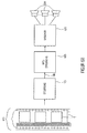
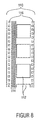
- Fig. 8 shows an exemplary film 110.
- Film information is applied to the film in spatial sequence, or during playback, respectively, in chronological order, for example video information or images 112, which are also referred to in English as “frames” or “video frames” and audio information or one or a plurality of analog or digital audio tracks 114, which in the digital case have "audio frames”.
- the film 110 has, by way of example, feed perforations 116 with the aid of which the film is played.
- the first method involves the storage of a time code on the data carrier, such as DTS (Digital Theater System) for Kinoton, or in an additional channel, which is connected to the audio signal.
- DTS Digital Theater System
- Examples are ancillary data by DAB and mp3.
- the time code is then used to play audio or additional information synchronously from an external data carrier, for example CD in DTS.
- Proprietary formats prevent the use of timecode extension by other extensions. Mutual disturbances of the extensions are not always preventable, an example of this is the use of ancillary data in mp3 for additional information and bandwidth expansion of various manufacturers.
- the second method is based on the misuse of analog audio tracks for storing time code as described e.g. in a prototype cinema equipped with an IOSONO system.
- a disadvantage of this method is that the analog track is present in all systems and is often used as a fallback solution in case of disturbances of the other systems, that is, an alienation of the analog track prevents the fallback option.
- the automatic switching to the analogue track which is installed in most cinemas, causes the timecode to be played back as an analog signal if no signal is present on the "more modern" Dolby Digital or DTS tracks.
- the redundant analogue reproduction must be switched off manually in the case of pure wave-field synthesis reproduction, which will be explained below, because otherwise the timecode can be heard via the redundant further loudspeakers.
- WFS Acoustic Wave Field Synthesis
- the WFS tries to reproduce the air vibrations of a real situation, which make up the sound, over a whole room.
- the wave field synthesis is to faithfully transfer the entire sound field to the room. This means that the virtual sound sources can be exactly spatially localized, and possibly even seem to exist in the middle of the sounded room, thus they can be bypassed.
- Systems with up to 200 loudspeakers in cinema systems and up to 900 loudspeakers in theater sound systems have already been realized.
- Wave field synthesis is based on Huygens' principle, which states that any point on a wavefront can be considered the starting point for an elementary spherical wave. By interference of all elementary waves, a new wavefront arises, which is identical to the original wave.
- the cinema Ilmenau in which the wave field synthesis is operated in two modes.
- the cinema is operated as a "real" wave field synthesis system, where the analog track of the 35 mm film stores the time code, as explained previously with regard to the second "abusive" method, and the WFS sound from an external one Medium, eg Hard disk or DVD, is leaked.
- the analog track of the 35 mm film stores the time code, as explained previously with regard to the second "abusive" method, and the WFS sound from an external one Medium, eg Hard disk or DVD, is leaked.
- the sound stored on each 35 mm film is read out and decoded by a Dolby processor, alternatively DTS or SDDS could also be used, the Dolby processor If necessary, automatically switches to the analog track, and maps the resulting multi-channel signal via WFS on virtual speakers.
- a Dolby processor alternatively DTS or SDDS could also be used, the Dolby processor If necessary, automatically switches to the analog track, and maps the resulting multi-channel signal via WFS on virtual speakers.
- a major disadvantage of the prior art described above is that the comparison between the stored audio signal and the audio signal sampled by the film is limited to a window of, for example, one minute in length. If the portion of the sound signal currently being scanned by the film is not in the range of the window of the stored sound signal, the search for a location in the film is unsuccessful or leads to a determination of a wrong location and thus to a false synchronization. In this case, the cinema audience hears the wrong sound to the picture.
- the object of the present invention is to provide an efficient concept for determining a location in a film.
- the present invention is based on the finding that a two-step approach, in which an approximate location in a film is first determined in a lower scan rate search window, and then based on this roughly determined location, accurately determines the location in the film With the second window being shorter and being scanned at a higher sampling rate, a faster and more efficient determination of a location in a film is made possible than the prior art described above.
- a method of detecting a location in a film comprising: a memory for storing film information deposited on a film in temporal succession, the stored film information being associated with a time scale, means for receiving one of A read portion of the film, and a synchronizer configured to compare a sequence of samples of the read portion on which a first sampling rate is based and a first search window of the stored film information to obtain a coarse result, and a sequence of samples of the in order to obtain a fine result indicative of the location of the film, wherein a position of the second search window in the stored movie information is different from the coarse result is dependent, wherein the first search window is longer in time than the second search window and wherein the first sampling rate is lower than the second sampling rate.
- the synchronization means is adapted to compare a sequence of samples of a read portion by correlation with a search window of the stored movie information.
- the synchronization means is adapted to compare the sequence of samples of the read portion underlying a first sample rate with a plurality of versions of the first search window, each version of the first search window being based on a different sample rate Coarse result, eg a more pronounced peak than the correlation result, and a sequence of samples of the read portion on which a second sampling rate is based, with a plurality of Compare versions of the second search window, each version of the second search window is based on a different sampling rate to obtain an accurate fine result for the determination of the location in the film.
- the device and the method for determining a position in a film can, for example, be used in a device for generating a control signal for a film event system that synchronizes film events with a picture display.
- Examples of movie events are audio sound, subtitles and special effects, where special effects e.g. Air currents, jiggling on the cinema chairs, odors or lighting effects on the side and rear wall may include.
- special effects e.g. Air currents, jiggling on the cinema chairs, odors or lighting effects on the side and rear wall may include.
- both different languages e.g. simultaneous playback of the original version and translations into other languages, as well as various audio techniques possible, such as the synchronization of digital surround systems such as wave field synthesis.
- the invention is not limited to movies for a moviegoer, but generally refers to movies or audio-video signals, whether or not they are This is about film or other media and storage media, such as magnetic tapes or hard drives, stored movie information is.
- the invention can also be used for pure sound systems without video or for example by means of a video ID synonymous for synchronization of pure video material, ie without sound, can be used with any event.
- FIG. 12 shows a basic block diagram of a device for generating a control signal for a film event system and an exemplary film 110, as described above with respect to FIG. Fig. 8 has been explained, wherein the means for generating a control signal, a means for storing 120 film information, a means for receiving a read from the film portion 140, a device 160 for comparing the read portion with the stored film information 112, 114 and means 180 for Determining the control signal based on the comparison and the time scale.
- the stored film information 112, 114 comprises, for example, the audio signals, the images or video signals or even marks which can already be found on films, and e.g. determine where the shutter will open or when the sound will be played or when the movie will stop.
- the stored audio and / or video signals are present, for example, in digitized form, preferably in compressed form, in order to reduce the memory requirement.
- One advantage of digitized storage lies in the simple and, above all, error-free duplication of the stored image of the film information.
- the film remains unchanged as previously described, producing only a stored image of the movie information once, e.g. in the production of the film.
- the audio signal contained on the audio track 114 is received by the receive device 140 and prepared for the compare device 160, for example, sampled at a given sample rate and as a portion of a given length or a given number of samples passed.
- the means 160 is adapted to compare this portion read from the film with the stored film information
- the means 160 for comparing may be arranged to compare the read portion with the entire stored film information, but preferably the read portion with a portion of the stored ones Film information compares to minimize the computational effort.
- the comparison can be done for example by cross-correlation, but also by calculating the difference, for example by calculating a compressed hash sum and search this in a database.
- the comparison may consist of the audio signal alone, the video signal alone, a comparison of the audio signal and the video signal and a combination with an evaluation of the aforementioned features.
- means 180 for determining determines control signal 190.
- Control signal 190 controls a film event system based on control signal 190 synchronized with the playback movie 110, for example, WFS audio signals Subtitles generated.
- the device for generating a control signal or in particular the means for determining the control signal 180 may be configured such that the control signal is any time code format, proprietary or standardized, such as the SMPTE (Society of Motion Picture and Television Engineers) standardized LTC (Longitudinal Time Code) time code format (LTC).
- SMPTE Society of Motion Picture and Television Engineers
- LTC Longitudinal Time Code
- Time-synchronized means that based on the control signal 190, the movie event system of one of the locations currently being played by the movie, which is assigned a time-on-scale time in the stored movie information, generates a concurrent event corresponding to that time scale.
- any film player may be used, any film formats, e.g. Silent films (eg, with video-based synchronization), analog or digital soundtrack, one or more parallel soundtrack, or any other storage media, such as cassettes or hard disks whose format can not be changed, or alternatively should, for example, continue to be compatible with the movie player, but at the same time other movie events should be synchronized.
- any film formats e.g. Silent films (eg, with video-based synchronization), analog or digital soundtrack, one or more parallel soundtrack, or any other storage media, such as cassettes or hard disks whose format can not be changed, or alternatively should, for example, continue to be compatible with the movie player, but at the same time other movie events should be synchronized.
- the audio signal is used as movie information for synchronization.
- the portion read from the film is scanned at a given sampling rate, hereinafter referred to as the test sampling rate, to produce a test tone signal and the stored movie information is stored in digital form, the stored film information being hereinafter referred to as the reference signal , and the test tone signal and reference tone signal are compared in the cross-correlation comparing means 160.
- the test signal sample rate and the reference signal sample rate are fixed, that is, constant.
- the means 160 for comparison may then be designed, for example, to generate a first correlation result at a first time on the basis of a first test tone signal and a first reference tone signal to determine a first time scale of the time scale, and at a second time a second test tone signal generating a second correlation result to a second reference sound signal to determine a second time scale of the time scale to determine therefrom, for example, a time difference or playback speed or to determine a speed difference as compared to a desired or reference playback speed.
- the means 180 for determining the control signal determines the control signal, for example, to synchronize the movie event system.
- a disadvantage of a constant sampling rate is that at a changing test playback speed, the correlation result deteriorates, and thus the accuracy of the determination of the time or the point in the film is inaccurate and thus the synchronization is worse.
- This disadvantage can be compensated by varying the sampling rates, ie the test sampling rate and / or the reference sampling rate.
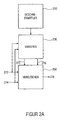
- FIG. 12 shows a principle block diagram of an apparatus for performing a correlation between a test sound signal that is playable at a variable playback speed and a reference sound signal that is a digitally stored version of the test sound signal
- the apparatus for performing a correlation comprises means 210 for determining a measure of a test signal Test playback speed, means 230 for varying a test sample rate or reference sample rate, and means 250 for comparing.
- the device 230 is designed to provide a test sampling rate with the test sound signal 270 is sampled to vary to produce a modified test signal 272 or to vary a reference sample rate to produce a modified reference sound signal 276 based on a reference sound signal 274.
- the means 230 for varying is further configured to vary the test sampling rate or reference sampling rate such that a deviation between a test playback speed associated with the test sound signal or a reference playback speed associated with the modified reference sound signal 276 is reduced or a deviation between a test playback speed associated with the modified test sound signal 272 and a reference playback speed associated with the reference sound signal 274, or a deviation between a test playback speed associated with the modified test sound signal 272 and a reference playback speed associated with a modified reference sound signal 276 , wherein the term playback speed or the problem of a variable playback speed will be explained in more detail below.
- the means 250 for comparing the modified test sound signal 272 and the reference sound signal 274, or the test sound signal 270 and the modified reference sound signal 276, or the modified test sound signal 272 and the modified reference sound signal 276 is designed to determine a result 278 of the correlation.
- FIG. 2a For example, in an apparatus for generating a control signal for a movie event system, such as shown in FIG Fig. 1 is shown used as means 160 for comparison.
- Fig. 2b shows a schematic block diagram of a preferred embodiment of an apparatus for performing a correlation between a test sound signal and a reference sound signal.
- FIG. 11 shows means 280 for storing a reference sound signal 274 which is a digital version of the test sound signal 270, the reference sound signal 274 having been generated once based on a given memory reference playback speed and a memory reference sample rate.
- test tone signal is played back at a variable test playback speed and sampled at a test sample rate to produce the test tone signal 270.
- the test-play-speed measurement means 210 of the test sound signal 270 controls the means 230 for varying on the basis of the test-playback-speed measurement.
- the means 230 for varying in turn controls a reference rate converter 232 and a variable sampler 234, wherein the sample rate converter 232 is configured to convert from the reference audio signal based on the memory reference playback speed and a memory reference sampling rate into a modified reference sound signal 276 corresponding to a reference audio signal which is based on a different memory reference playback speed and / or memory reference sampling rate, and wherein the variable sampler 234 is adapted to sample the test sound signal at a different sampling rate, that is to say from the standard or basic sampling rate, to produce a modified test sound signal 272.
- the means for performing a correlation may also be such that the test sound signal 270 is always supplied via the variable sampler 234 to the means 250 for comparison, the variable sampler 234 then being arranged such that one of the standard or variable test sample rates Basic sampling rate, and further that the reference sound signal 274 is always supplied to the means 250 for comparison via the reference sampling rate converter 232, the reference sampling rate converter 232 being arranged to unmodify the reference sound signal 274 when appropriately driven by the means 230 for varying to the device 250 for comparison.
- Fig. 2b selected representation of the separate supply of the test sound signal 270 with respect to the modified test sound signal 272 and the reference sound signal compared to the modified reference sound signal 276 to the means 250 for comparison, serves to represent the alternative execution possibilities or realization possibilities.
- the means 250 for comparing is configured to compare the modified test sound signal 272 with the unmodified reference sound signal 274, no reference sample rate converter 232 is necessary or instructs the apparatus to perform correlation Fig. 2b no reference sample rate converter 232.
- a comparing means 250 configured to compare the unmodified test sound signal 270 with the modified reference sound signal 246 does not include a variable sampler 234.
- the means 280 for storing is a means for storing a movie information, wherein the stored movie information is associated with a time scale, and the test sound signal 270 is, for example, a movie sound signal.
- the device for performing a correlation according to Fig. 2b can then, for example, as means for comparing 160 according to Fig. 1 be used.
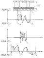
- FIG. 11 shows a portion of an exemplary film 110 having a soundtrack 114 as in FIG Fig. 1 previously described.
- two locations of the film 110 are plotted, a first location, hereinafter referred to as location L 1 , and a second location, hereinafter referred to as location L 2 .
- Fig. 2c.2 shows an exemplary course of the test sound signal that corresponds to the in Fig. 2c.1 is assigned to section described between the location L 1 and L 2, further comprising the time at which the position L 1 of the movie is played back is referred to as time T 1 and the time at which the position L 2 of the movie is playing, is referred to as time T 2 .
- T 2 - T 1 L 2 - L 1 / v ,
- n .DELTA.L / .delta.t ⁇ v respectively.
- n .DELTA.L ⁇ f / v . that is, the number of sampling periods or samples for a given film portion ⁇ L is proportional to Sampling rate f or antiproportional to the sampling period .DELTA.t and antiproportional to the playback speed v.
- the quotient "f / v" or the product " ⁇ t ⁇ v" must be constant if n or the number of samples n + 1 should be constant. If the first sample value is the same in this case, the individual samples are the same under the condition mentioned above.
- the stored portion of the movie information or the test sound signal is represented and stored by n memory + 1 reference samples, for example.
- Fig. 2c.2 to 2c.4 exemplary samples or storages of the film portion between the location L 1 and the location L 2 for a constant sampling rate f and a variable sampling rate ⁇ t and a variable playback speed, respectively
- Fig. 2.c2 shows an exemplary sample or storage for a first playback speed v 1
- Fig. 2c.3 shows a sample or storage of the same film section at a second playback speed v 2
- Fig. 2c.4 shows a scan of the same film section for a third scan speed v 3 .
- v 1 is half the size of v 2 and twice as large as v. 3
- Fig. 2c.2 to 2c.4 corresponds to a constant sampling rate
- an increase in the playback speed v of a temporal compression of the audio signal ie a doubling of the playback speed v 1 off Fig. 2c.2 leads as in Fig. 2c.3 represented to a halving of T 2 - T 1 and n
- a reduction of the playback speed v to a temporal extension of the audio signal ie a halving of the playback speed v 1 from Fig. 2c.2 leads as in Fig. 2c.4 represented to a doubling of T 2 -T 1 and n.
- the Fig. 2d.1 and 2d.2 essentially correspond to the Fig. 2c.1 and 2c.2 .
- time T 0 which represents the time associated with point L 0 based on a given playback speed
- time T 3 which represents the time associated with point L 3 based on a given playback speed
- T 0 defines, for example, the time on the time scale, which is assigned to the point L 0
- the time T 1 defines the time on the time scale
- the point L 1 defines the time on the time scale
- the time T 2 defines the point in time on the time scale defining point L 2
- time T 3 the time on the time scale associated with point L 3 on the film.
- Fig. 2d.3 equals to Fig. 2c.2 .
- Fig. 2d.3 a currently read one of the film applied to the film information or the test sound signal 270 and Fig. 2d.2 a stored film information or a reference sound signal, wherein in an optimal case, here by the Fig. 2d.2 and Fig. 2d.3 and the memory sampling rate at which the reference sound signal was generated coincides with the playback speed of the test sound signal and the sampling rate of the test sound signal.
- the quotient of memory sampling rate f memory and memory playback speed v stores the quotient of the sampling rate for the test sound signal f and the playback speed of the test sound signal v coincide.
- the reference sound signal or a portion of the reference sound signal which is defined by T 1 and T 2
- the test sound signal representing the portion between T 1 and T 2
- correlation clear local maximum or a correlation peak are obtained, as exemplified in Fig. 2d.4 is shown.
- the position of the peak in turn indicates the time shift of the test sound signal relative to the reference sound signal or the search window. Based on this, the current time with respect to the stored time scale can then be determined.
- the Fig. 2d.5 to 2d.8 show in contrast to the Fig. 2d.1 to 2d.4 an example in which the playback speed of the test sound signal, shown in Fig. 2d.7 compared to the playback speed of the test sound signal, as in Fig. 2d.2 is shown reduced.
- FIG. 10 illustrates an example trace of a reference tone signal based on a memory sample rate f memory and a memory playback speed v memory .
- Fig. 2d.7 shows an exemplary course or exemplary sampling of the test sound signal, based on a comparison with 2d.3 or Fig. 2d.6 unchanged test sampling rate f, however, a changed, reduced playback speed v 'of the test sound signal.
- this means that in the same time interval ⁇ T at a reduced speed v 'only a lesser portion or a portion of lesser length ⁇ L' according to ⁇ L ' v' ⁇ ⁇ T is played back by the film is reached on the currently playing film after the period .DELTA.T only one point L ' 2 , which lies before the point L 2 , as shown in Fig. 2d.5 is shown. Relative to the reference sound signal and the time scale associated therewith, the point L ' 2 is assigned the time T' 2 of the timescale, as shown in FIG Fig. 2d.7 will be shown.
- the result of the comparison will be degraded, since, even under otherwise optimal conditions, the test sound signal and the reference sound signal represent two different spatial sections of the film.
- the result of the comparison becomes worse the greater the deviation of the memory playback speed from the test playback speed deviates.
- the magnitude of the local maximum or peak decreases and the maximum itself becomes wider and flatter, for example, so that the time determination with respect to the time scale becomes increasingly inaccurate until it is no longer possible.
- the playback speed of the test tone signal will not only vary between different movie players, but may vary during a movie. Accurate tracking is essential to ensure synchrony throughout an entire movie.
- the device for performing a correlation therefore varies the sampling rate of the test sound signal or the sampling rate of the reference sound signal in order to detect the adverse effect of a variable speed of the test sound signal, as described above, according to the above-described condition, the quotient of the sampling rate and the playback speed of the test sound signal and of the reference sound signal must be equal in order to represent the same film section with the same sampling values.
- the change in playback speed is effected by sample rate conversion, whereby the stored reference sound signal 274 is appropriately interpolated, for example, to generate a reference sound signal at the sampling rate corresponding to the changed playback speed.
- Fig. 2d.1 - 2d.8 illustrate simplified examples in which, for the sake of clarity, it has been assumed that the memory playback speed v memory corresponds to a normal or standard playback speed of a playback device for generating a test sound signal.
- the quotient of sample rate f and playback speed v is the magnitude that must be the same for the reference sound signal and the test sound signal to represent the same portion of the film with the same samples as previously indicated.
- a double playback speed can also be used if the sampling rate is simultaneously doubled.
- the means 210 for determining may determine a measure of a test playing speed based on the result 278 of the correlation.
- One possibility is to use a single correlation result for the determination of a measure of the playback speed, for example, by comparing an amplitude of a peak with a predetermined threshold to determine whether a deviation between a playback speed of a test sound signal and a reference sound signal is within a predetermined range.
- At least two different reference sound signals which are based on different reference sampling rates and / or different reference playback speeds, are compared with the test sound signal to obtain the results of the correlation, for example by means of a quality assessment relating to Fig. 5 will be explained in more detail in order to determine from these a most similar Referenztonsignal and thus based on the known sampling rate and the known memory playback speed, a measure of the playback speed of the test sound signal.
- the different reference sound signals can be formed one after the other and compared with the test sound signal or simultaneously formed and compared.
- a particularly preferred embodiment of the apparatus for performing a correlation generates three reference sound signals based on different reference sampling rates, wherein the reference sound signal of the middle of the three sampling rates is based on the reference sampling rate of the reference sound signal which in a previous comparison is the best quality or maximum match with the test sound signal and the two other reference sound signals each have a reference sampling rate higher or lower than the reference sampling rate of the middle reference sound signal.
- This is controlled by the means 230 for varying on the basis of an output of the means 210 for determining the measure of the test playing speed. This ensures that the reference sampling rate or the reference playback speed of the reference sound signal is matched to the playback speed or reference sampling rate of the test sound signal.
- Fig. 3a shows an exemplary movie, as in Fig. 8 and a basic block diagram of a device for determining a location in the film.
- an exemplary embodiment of the device for detecting a position in a film can be used in a device for generating a control signal for a film event system, as described, for example, in US Pat Fig. 1 is shown used as means 180 for determining the control signal.
- the device for determining a location in a film has a memory 320 for storing a reference fingerprint representation of the film information, wherein the fingerprint representation is designed so that a time profile of the fingerprint representation depends on a time profile of the film information, and wherein a stored reference fingerprint representation is assigned a time scale , means 340 for receiving a portion read from the film, means 350 for extracting a test fingerprint representation from the read portion, and means 36 for comparing the test fingerprint representation with the reference fingerprint representation to determine the location based on the comparison and the timescale to determine in the movie.
- the fingerprint representation comprises a representation in the form of a spectral flatness, wherein a time profile of the fingerprint representation comprises a time profile of the spectral flatness.
- Fig. 3b.1 shows an exemplary film 110 as in FIG Fig. 8 shown.
- a fingerprint is determined for particular spatial and temporal portions of the film.
- FIG. 16 shows a first portion including the portion from the location L 100 to L 113 and T 100 to T 113 , respectively, and a second portion including the portion from the location L 103 to the location L 116 and from the time T 103 up to the time T 116 includes. Based on these sections, a fingerprint associated with this section is generated based on, for example, spectral analysis, Fourier transformation, or other feature extraction methods.
- the fingerprint comprises the spectral flatness ⁇ x 2 , which is calculated from the course of the power density spectrum, so that the value of the spectral flatness is determined for each section, and depending on the time course of the film information, for example Sound signal, a sequence of spectral flatness, which are stored in the memory 320 with the associated time scale.
- Sampling rate, length or duration of the section, or the distance between two consecutive sections are determined according to the requirements for, for example, uniqueness or accuracy of determining the location in the film.
- the longer the section the clearer the feature's feature in general, the higher the sampling rate and / or the smaller the distance between two sections, the more accurately the location in the movie can be determined.
- the higher the sampling rate the longer the sections and the smaller the distances between the sections, the higher the memory requirement for the reference signal or the request for the computing power during signal processing.
- a significant advantage of the fingerprint representation in the form of the spectral flatness is its small memory requirement compared to, for example, a complete storage of the power density spectrum for a same section.
- a trace of spectral flatness is used as a fingerprint for a portion.
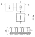
- Fig. 4 shows an exemplary film 110 as in FIG Fig. 8 and an apparatus for detecting a location in a film having film information applied in a temporal sequence.
- an exemplary embodiment of the device for detecting a position in a film can be used in a device for generating a control signal for a film event system, as described, for example, in US Pat Fig. 1 is shown used as means 180 for determining the control signal.
- the means for determining a location includes a memory 420 for storing film information deposited on a film in sequence, with a time scale associated with the stored movie information, means 440 for receiving a portion read from the film, and synchronization means 460 configured to compare a sequence of samples of the read portion underlying a first sampling rate and a first search window of the stored movie information to obtain a coarse result, and a sequence of samples of the read portion having a second sampling rate, and comparing a second search window of the stored movie information to obtain a fine result indicative of the location of the movie, wherein a position of the second search window in the stored movie information depends on the coarse result, and wherein the first search window is longer in time than the second search window, and further wherein the first scan rate is lower than the second scan rate.
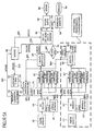
- Fig. 5a shows an exemplary film 110 as in FIG Fig. 8 and a preferred embodiment of a device for generating a control signal for a film event system, which is formed on the basis of an applied on the film analog audio track a read portion of the audio signal or test tone signal and a stored digital version of the test tone signal hereinafter referred to as Referenztonsignal, which is associated with a time scale, to determine by comparing the test sound signal and the reference sound signal by means of the time scale, the control signal.
- Referenztonsignal which is associated with a time scale
- An input of the first means 562 for correlation, an input of a second means 564 for correlation, and an input of the third means 566 for correlation are coupled to an output of a sample rate converter 232, referred to as a sample rate converter (SRC). connected.
- SRC sample rate converter
- An output of the first means 562 for correlation, an output of the second means 564 for correlation and an output of the third means 566 for correlation are connected to an input of a first means 568 for quality assessment.
- the quality assessment means 568 is coupled to the sample rate converter 232 and to a sampler selection means 570, an output of the sampler selection means 570 being connected to an input of a timer 582.
- the timer 582 in turn is connected to the stored soundtrack 522 for storing the soundtrack, wherein an output of the soundtrack storing means 522 is connected to an input of the sample rate converter 232.
- An output of the first feature extractor 552 is connected to an input of a feature comparison device 554 having, for example, a feature classifier and a database of features, an output of the feature comparison device 554 having an input of the timer 582 is connected.
- a feature comparison device 554 having, for example, a feature classifier and a database of features
- An output of the timer 582 is coupled to an input of a time code generation means 584 having a time code database or coupled to a time code database, and an output of the time code generation means 584 is connected to an input of a time code slicer 586, the means 586 is adapted for time code smoothing to output a time code 592, and further wherein an output of the time code smoothing means 586 is connected to an input of a word clock generator 588, which in turn is adapted to output a word clock signal 594.
- the apparatus for generating a control signal for a film event system optionally further comprises a second film tone sampler 542 'associated with a second A / D converter 544 ', the second A / D converter 544' having a second feature extractor 552 ', a fourth means 562' for correlation with a fourth reference sound signal based on the first sampling rate, a fifth means 564 'for a correlation with a fifth reference sound signal based on the second sampling rate and a sixth means 566 'for correlation with a sixth reference sound signal connected at the third sampling rate.
- An output of the fourth means 562 'for correlation, an output of the fifth means 564' for a correlation and an output of the sixth means 566 'for a correlation are connected to an input of a second means 568' for quality evaluation, wherein an output of the second Further, means 568 'for quality evaluation is connected to an offset compensation 569 and another output is connected to an input of the sample rate converter 232, and further wherein the means for offset compensation 569 is connected to the sample selection 570.
- the first film tone sampler 542 also referred to as a main sampler, is positioned so that there is enough time for the device to generate a control signal to lock itself up.
- the first film tone sampler 542 thus provides a pre-delayed signal.
- At Aufsynchronisationszeit still adds the correlation window width or width of the portion of the test sound signal.
- the time difference for the pre-delay can be set exactly. As a first clue, three seconds is recommended.
- the first film tone sampler 542 reads the sound signal from the soundtrack of the film, and samples the sound signal from the soundtrack of the film, and passes this signal to the first A / D converter 544, where the first A / D converter 544 is formed to generate a digital audio signal or test tone signal based on the sampling rate of the first film tone sampler 542 and the playback speed of the film from which the audio track or movie information is being read.
- test fingerprint representation On the basis of the test sound signal 270, one or a plurality of features is extracted or a test fingerprint representation is formed. For example, the spectral flatness is used as a characteristic or fingerprint for the feature extraction or fingerprint representation.
- the test fingerprint representation is then compared by the feature comparison device 554 with a reference fingerprint representation, as previously noted, wherein the fingerprint representation is such that a time history of the fingerprint representation depends on a temporal history of the movie information, and where a A reference fingerprint representation stored in feature 554 is associated with a time scale, and means 554 for comparing is adapted to determine a location in the film based on the comparison of the test fingerprint representation with the reference fingerprint representation and the time scale respectively a time code signal 554Z produce.
- the sampling rate converter easily generates the same signal based on the stored reference sound signal 274 different sampling rates, ie modified reference tone signals, for the correlations to be calculated in parallel.
- modified reference tone signals the case where a modified reference sound signal has the same sampling rate as the original reference sound signal is included herein, so that the discussion of the Fig. 5 Furthermore, the term reference tone signals is generally used.
- sampling rate converter 232 generates three reference sound signals 276 and modified reference sound signals 276, respectively, wherein a first reference sound signal is based on a first sampling rate and supplied to first means 562 for correlation, wherein a second reference sound signal 276 is based on a second sampling rate and the second means 564 for correlation, and a third reference sound signal 276 based on a third sampling rate and supplied to a third means 566 for correlation.
- the sample rate converter 232 provides low-level, sample rate-different signals to the correlation device 562, 564, 566, respectively, with the sample rate always set in correlation with the previous measured maximum peak-to-noise value from the correlation becomes.
- a correlation gets a modified reference sound signal with this sampling rate
- another correlation gets a little lower, one level lower, and another correlation gets a slightly higher graduated sampling rate. This ensures that the sample rate converter can, for example, tune or synchronize to a change in the speed of the analog audio signal.
- the means 522 for storing the soundtrack and the sampling rate converter 232 are preferably designed to use a window width of 2 n, in order to calculate low-cost large correlation windows by means of the fast Fourier transformation (FFT). There may be more than three correlations in parallel be calculated to compensate for sudden jumps in the soundtrack.
- the correlation window is chosen to be large in order to obtain a clear correlation peak. In order to obtain the recognition accuracy of the correlation peak under a sample or a sampling period, it is possible to work with oversampling of the input signal or test tone signal.
- the sound track storing means 522 outputs the reference sound signal in the length of the correlation window depending on the supplied time code signal 582Z of the timer 582, the correlation window being the search window in which the test sound signal is searched.
- the first quality judging means 568 is configured to perform a maximum value search in the cross-correlated ones of the signals and the amounts of the cross-correlates, depending on the height of the correlation peak compared to other peaks in the cross-correlated one the peak-to-noise distance to determine the quality of each individual correlation.
- the best quality reference tone is determined and the displacement of the peak from the search window is determined based on the position of the peak of the best quality reference tone, for example as a time code difference between the measured and currently valid time code or relative time code issued.
- the first quality judging means 568 sends a control signal 568A to the sampling rate converter 232, which for example distinguishes only the three signal values "0", “+1” and "-1", for example at “0" the sampling rates the last sample rate conversion or correlation, because the correlation result from the modified Reference tone signal with the average sampling rate was determined to be the highest quality, at "+1” the sampling rates are increased by one step compared to the last sampling rate conversion or correlation, because the correlation result from the modified reference tone signal with the highest sampling rate was determined to be the highest quality, and at "-1" the sampling rates are reduced by one step over the previous sample rate conversion since the correlation of the test tone signal and the modified reference tone signal with the lowest reference sample rate had the best correlation-to-peak-to-noise ratio ,
- the sample rate converter will be e.g. is increased or decreased by one sample rate delta value, or so driven that it does not sample rate conversion.
- the correlation serves to address two important aspects. First, determining the location in the film or determining the point in time in the film on the basis of the time code difference from the correlation. Second, determining the measure of the playback speed to determine the optimum reference sample rate or sample rate conversion of the reference sample rate, respectively.
- the adaptation of the sampling rates or the recapture of adapted playback speeds in turn enables better correlation results and thus in turn improves the timing or determination of the location in the film and thus in turn improves the synchronization and the prediction.
- a preferred embodiment according to Fig. 5 is designed, by means of a signal analysis, to detect signal parts with specific characteristics in order to then hide them during synchronization and thus false detections or to prevent synchronization or to avoid random fluctuations of the time axis.
- Such characteristics can be, for example, the loudness of the signal part or the "problem" of a signal and the signal analysis or detection of problematic parts on the basis of SNR (Signal to Noise Ratio), PNR (Peak to Noise), Spectral power or line density spectral, spectral flatness, or averaging a time series.
- SNR Signal to Noise Ratio
- PNR Peak to Noise
- Spectral power or line density spectral spectral flatness
- spectral flatness or averaging a time series.
- the time code difference can be recognized as invalid. Or, for example, if multiple peaks with similar peak-to-noise ratios are detected, the time code difference may also be identified as invalid.
- the quality of correlations with quiet signal portions is lower than correlations with loud signals because of the higher quantization noise in the digital sample, therefore, quiet signal portions are thresholded or adaptively masked to coincidental ones To avoid fluctuations in the time axis.
- the signal energy can be another quality feature.
- Another example is the hiding of problematic, because recurrent signal parts to avoid ambiguity and thus, for example, incorrect synchronization.
- Problematic signal parts or sections can also be signaled as metadata, for example, in order to hide these signal parts, regardless of the quality of the current correlation.
- the time code generation means 584 is designed to convert based on the time code signal 582Z of the timer 582, which may for example be based on an internal or proprietary time code, into a standardized time code or a time code signal based on a standardized time code, for example.
- the timer 582 is controlled by an internal clock (frequency of correlations), a coarse audio ID fingerprint, such as the time code signal 554Z from the feature determination, and the detected correlation difference, such as from the correlation determined time code difference signal 570Z of the device 570 for scanner selection.
- the timer must prioritize correlation signal (highest priority), time code from feature determination, and internal clock (lowest priority).
- the time code smoothing means 586 is arranged to smooth the time code signal 584Z so as to avoid, for example, a hopping time code or, if there are time codes from the correlation, to find meaningful intermediate values, e.g. Compensate for pauses in the analog tone.
- the time code signal 592 generated by the time code slicer 586 is preferably a standard time code with which the movie event system is synchronized. However, the time code signal 592 may also be used to generate a corresponding sample clock or sample clock via a very slowly regulating phase locked loop (PLL) if the included audio reproduction system is digital. Such phase locked loops are available as finished devices and are not the subject of this patent.
- PLL phase locked loop
- more than one telecine with time-varying offset from the projection lens can improve the robustness of film damage or synchronization poorly suited sections are used.
- a second film tone sampler 542 ' may then be used, for example, since the second film tone sampler 542' is already present in conventional cinema systems. Breaks in the analog tone can hereby be bridged by the film tone samplers 542, 542 'attached at different locations on the motion picture film, since the probability increases with short pauses in the film sound, the at least one scanner, the first film sound scanner 542 or the second film sound scanner 542', enough signal for a correlation and the associated synchronization provides.
- different scanners e.g. for analog sound, Dolby Digital sound (including decoder), DTS digital sound (including DTS decoder) or another sound, and a combination of the above may be used as the reference soundtrack and / or test soundtrack.
- individual traces can be used for comparison using averaging, majority decision or prioritization, automatically or via metadata, the time information generated therefrom, as well as a downmix to mono.
- different scanners may be used for different audio formats and / or different film scanners with different timing offsets.
- Using a downmix on mono has the advantage that when the monaural track is used as a stored audio track, it saves less than storing five channels, for example.
- the storage of different, ie more than one soundtrack, ie no downmix means that all channels are stored independently of each other and then, for example, as previously explained, making corresponding majority decisions to then perform the synchronization using a particular channel, the actual soundtrack, and a corresponding channel of the stored soundtrack.
- the initialization phase or the first synchronization and the resynchronization after a recording pause form two critical phases during a film projection or a synchronization of a film event system.
- preferred embodiments initially calculate more than three parallel correlations since no synchronization has yet occurred, that is, more than three reference tone signals of different sample rates are compared with the test tone signal to determine the correct sample rate or playback speed of the test tone signal as quickly as possible.
- the first feature extractor 552 and the feature classification means 554 in combination with the database provide a coarse absolute time code value defining a coarse location in the film to determine, in a second step, for example, by the correlation, a fine determination of the location of the film or film to perform a fine time code determination.
- a second step for example, by the correlation, a fine determination of the location of the film or film to perform a fine time code determination.
- a point in a movie or point assigned to the point can be assigned on a time scale depends on the sampling rate of the reference sound signal and the sampling rate of the test sound signal, the higher the sampling rate, the more accurate the location in the film can be determined.
- a lower sampling rate has the advantage that with the same number of samples, a longer portion of the reference sound signal or the test sound signal can be represented.
- a rough determination of a location in a film is to be made by displaying a longer portion of the film by a reference sampling signal at a lower sampling rate, and also obtaining a test tone signal by sampling at a lower sampling rate.
- a higher sample rate reference tone signal and a higher sample rate test tone signal are used to finely determine the location in the film.
- the window length is adjusted when correlated.
- time-long windows but a reduced sampling rate of the signals are used, if a time is about to be found and only tracked, short windows may even be used with oversampling of the signals to achieve higher temporal accuracy.
- a "compatible reproduction” of the "old" audio format can take place until the exact position is determined.
- a "compatible" playback of the "old” audio format can be done if the synchronization has been significantly lost until the exact position is determined again.
- the scanner selection means 570 and the offset compensation means 569 are necessary only in embodiments with more than one film sound scanner.
- the means 570 for selecting the scanner decides whether the result or time code difference of the first quality assessment means 568 (568Z) or the result or time code difference 568Z 'of the second quality assessment means 568' is passed on to the timer 582 for determining a location in the film and a time code 582Z, respectively.
- the different reference sound signals of different reference sampling rates can also be generated successively and compared with the test sound signal to determine the measure of the playback speed of the test sound signal and the optimum reference sampling rate, respectively.
- more than three modified reference sound signals may be compared to the test sound signal, in parallel or serially, to enable fast synchronization not only in the initial phase, but also during movie screening, the film event system for larger cracks in the film, eg by cuts or in film missing sections causes faster sync to the current spot in the movie.
- a synchronization of a film event system can also take place on the basis of the images applied to the film, both for an evaluation of features or fingerprints and for a correlation of a test image signal with one or a plurality of reference picture signals.
- the correlation of audio and / or video signals for determining the temporal location in an audio and / or video stream can be used, and a synchronous playback can be controlled on the basis of this timing.
- the determination of an audio and / or video signature from the raw material in the form of an audio ID / video ID (ID) for roughly determining the time in a long AV stream may also be used to synchronize to allow any position.
- ID an audio ID / video ID
- the basic approach of the invention is, for example, to digitally store the already existing analog tone, in order then to synchronize it to the motion picture film by means of correlation and other feature determination with the analog sound track.
- the output signal or control signal of the device for generating a control signal or of the synchronizing device can be any time code format.
- a data set for the device for generating a control signal or for the synchronization device must be created during production.
- the data carrier includes the digitized analog audio track, e.g. in dolby stereo format as found on the roll of film, feature data about the soundtrack and matching timecodes.
- Fig. 5b.1 shows an exemplary film 110 with a soundtrack 114, as already in FIG Fig. 8 described.
- a reference sound signal 274 is read from the means 522 for storing an audio track, and a modified reference sound signal is read out by means of the sample rate converter 232 Fig. 5b.2 generated, the associated time 0 represents a film portion of the spot L 0 to the position L 3 or the site of the L 0 T or a corresponding time code and the location L 3 assigned time T 3 and time code.
- Fig. 5b.4 shows the result of the correlation of the modified reference sound signal according to Fig. 5b.2 and the portion of the test tone signal Fig. 5b.3
- the quality assessment 568 it is not necessary for the quality assessment 568, the knowledge of the absolute time T 0 or the time T 1 , since, for example, the timer 582 the last absolute Time or absolute time code and only the time code difference 570Z needed to determine the updated absolute time or time code.
- the difference can be represented, for example, from the position of the peak with respect to the time of the beginning of the search window.
- the peak is the fourth sample, ie, the test tone signal Fig. 5b.3 is off by "3 ⁇ ⁇ t" from the reference sound signal Fig. 5b.2 where ⁇ t is the sampling period corresponding to the modified sampling rate.
- the advantage of the adapted to the variable playback speed of the test sound signal sampling rate or playback speed of the reference sound signal advantageous to wear, since the .DELTA.t is adapted to the playback speed, a more accurate determination of the location in the film or displacement relative to the search window is possible than at a fixed sampling rate of the reference sound signal, since then only multiples of this sampling rate are generated for a determination of the location in the film.
- the time T 0 of the search window or reference sound signal can be equal to the T 1 of the previous correlation, since the film is played only forward.
- FIG. 12 shows an embodiment of a movie system in which a device 100 for generating a control signal 190 is coupled to a movie event system 600, thereby generating the device 100 for generating a control signal based on the movie 110 as in FIG Fig. 8
- the control signal 190 for example a time code, is synchronized with the movie event system 600.
- FIG. 3 shows a film system having a device 100 for generating a control signal 100 and a wave field synthesis system 610 as an exemplary film event system, wherein the embodiment of the wave field synthesis system 610 comprises means 620 for controlling the wave field synthesis system, a digital memory 622 for the wave field synthesis audio signals, and a plurality of loud speakers 624 for the wave field synthesis system.
- the control signal generating device 100 Based on the film 110 or, for example, an analog movie soundtrack 114, the control signal generating device 100 generates the control signal 190 to lip-sync a wave analog audio audio experience to an originally analog-converted movie.
- wave field synthesis system 610 can of course also be synchronized lip-synchronously by means of the device 100 for generating a control signal.
- other audio systems for example digital audio systems or digital surround audio systems, can of course also be synchronized lip-synchronously by means of the device 100 for generating a control signal.
- Fig. 7 shows an exemplary movie, as in Fig. 8 an exemplary digitally stored reference sound signal 720 and a time scale assignment.
- the analog audio signal is sampled at a given playback speed and rate, for example, 44.1 kHz, and audio portions of, for example, 10 ms are stored as a so-called audio frame, that is, the digital reference sound signal is present on the memory as a result of audio frames.
- the assigned time of a time scale can then consist, for example, of numbering the audio frames from 0 or 1 in ascending order as the time code or time scale.
- Time code TC1 corresponds to audio frame AF1 in FIG Fig. 7 or, for example, to find the start time or end time of an audio frame as the time code, eg, for the first audio frame, either 0 ms or 10 ms if an audio frame has a duration of 10 ms.
- Timecodes usually have formats such as hour: minute: second: frame, whereby the frame is more commonly used refers to video frames with eg 24 frames per second (movie).
- a time scale or time code can therefore, for example, assign a plurality of audio frames to a video frame or define an audio frame as the smallest time scale unit. Accordingly, the time code or the time scale then, for example, 4 audio frames assign a time code, see TC1 'in Fig. 7 comprising four audio frames AF1 -AF4 or assigning a single Audi frame to a time code, see TC1 in FIG Fig. 7 to which an audio frame AF1 is assigned.
- the audio frames may also represent temporally overlapping sections of the audio signal.
- the control signal 190 may be formed, for example, as a time code, but also as a sequence of pulses, wherein, for example, each pulse corresponds to a time scale unit and similar to a relative time code, the film event system accumulates the pulses to synchronize with the film.
- a further exemplary embodiment in order, furthermore, to have available, for example, an analog audio signal as a fallback, but at the same time also to realize a time code for synchronous additional services, offers the approach of embedding a watermark in the audio and / or video signal.
- Advantage of this solution is that even with "difficult" audio signals, such as very quiet passages or even similar "monotonous" noises, a clean clock recovery is possible.
- the complete set of the relevant Watermark claims in particular in the field of searching for the correct clock rate or the readjustment of the sampling rate, makes sense for this variant.
- the decisive disadvantage of this approach is that the actual film must be changed or a new version or copy of the film must be created in order to embed the Watermarks in the audio and / or video signal can.
- the method according to the invention can be implemented in hardware or in software.
- the implementation may be on a digital storage medium, in particular a floppy disk or CD with electronically readable control signals, which may interact with a programmable computer system such that the method is performed.
- the invention thus also consists in a computer program product with a program code stored on a machine-readable carrier for carrying out the method according to the invention, when the computer program product runs on a computer.
- the invention can thus be realized as a computer program with a program code for carrying out the method when the computer program runs on a computer.
Landscapes
- Engineering & Computer Science (AREA)
- Physics & Mathematics (AREA)
- General Physics & Mathematics (AREA)
- Signal Processing (AREA)
- Multimedia (AREA)
- Signal Processing For Digital Recording And Reproducing (AREA)
- Camera Data Copying Or Recording (AREA)
- Indexing, Searching, Synchronizing, And The Amount Of Synchronization Travel Of Record Carriers (AREA)
- Television Signal Processing For Recording (AREA)
Claims (9)
- Dispositif pour détecter un emplacement dans un film (110), aux caractéristiques suivantes:une mémoire (420) destinée à mémoriser des informations de film (112, 114) placées sur un film (110) dans l'ordre temporel, aux informations de film mémorisées étant associée une échelle de temps;un moyen (440) destiné à recevoir et balayer le signal d'un segment lu du film (110);un moyen de synchronisation (460) réalisé de manière à comparer quant à leur coïncidence une succession de valeurs de balayage du segment lu basées sur un premier taux de balayage et une première fenêtre de recherche des informations de film mémorisées, pour obtenir un résultat approximatif, et à comparer quant à leur coïncidence une succession de valeurs de balayage du segment lu basées sur un deuxième taux de balayage et une deuxième fenêtre de recherche des informations de film mémorisées, pour obtenir un résultat fin indiquant l'emplacement du film (110), une position de la deuxième fenêtre de recherche dans l'information de film mémorisée étant fonction du résultat approximatif, une fenêtre de recherche étant définie par un premier moment (T0) et un deuxième moment (T3) sur l'échelle de temps, la première fenêtre de recherche étant plus longue dans le temps que la deuxième fenêtre de recherche et le premier taux de balayage étant inférieur au deuxième taux de balayage.
- Dispositif selon la revendication 1, dans lequel le moyen de synchronisation (460) est réalisé de manière à comparer une succession de valeurs de balayage d'un segment lu au moyen d'une corrélation avec une fenêtre de recherche des informations de film mémorisées.
- Dispositif selon la revendication 1 ou 2, dans lequel le moyen de synchronisation (460) est réalisé de manière à comparer la succession de valeurs de balayage du segment lu sur base d'un premier taux de balayage avec une pluralité de versions de la première fenêtre de recherche basées, chacune, sur un taux de balayage différent, et la position de la deuxième fenêtre de recherche est fonction de la version de la première fenêtre de recherche pour laquelle un écart entre une vitesse de reproduction associée à la succession de valeurs de balayage du segment lu et une vitesse de reproduction de fenêtre de recherche associée à une version de la première fenêtre de recherche est minimal.
- Dispositif selon la revendication 3, dans lequel le moyen de synchronisation (460) est réalisé de manière à déterminer la position de la deuxième fenêtre de recherche sur base d'une première fenêtre de recherche dont le résultat de corrélation déterminé au moyen d'une corrélation présente, comparé à un ou une pluralité de résultats de corrélation d'une ou d'une pluralité d'autres premières fenêtres de recherche, une distance de bruit de crête supérieure.
- Dispositif selon l'une des revendications 1 à 4, présentant par ailleurs un autre moyen destiné à recevoir un segment lu du film, le segment étant différent du segment qui est reçu par le moyen destiné à recevoir.
- Dispositif selon l'une des revendications 1 à 5, dans lequel le moyen (420) destiné à mémoriser est réalisé de manière à mémoriser un mélange descendant, et dans lequel le moyen (440) destiné à recevoir est réalisé de manière à recevoir une pluralité de signaux de test d'une pluralité de pistes sonores et à générer un mélange descendant.
- Dispositif selon la revendication 1, dans lequel le moyen (420) destiné à mémoriser est réalisé de manière à mémoriser, en outre, au moins un autre type d'informations de film,
présentant au moins un moyen destiné à recevoir supplémentaire, l'un moyen supplémentaire étant réalisé de manière à lire du film un segment d'un autre type d'informations de film que le moyen (440) destiné à recevoir,
dans lequel un moyen (160) destiné à comparer est réalisé de manière à comparer les segments reçus des au moins deux types d'informations de film différents avec les types correspondants d'informations de film mémorisées, et
un moyen (180) destiné à détecter est réalisé de manière à déterminer, à partir des au moins deux résultats de comparaison basés sur les au moins deux types d'informations de film différents, par établissement de la moyenne, une décision de majorité ou de priorité d'un signal de commande (190). - Procédé pour détecter un emplacement dans un film (110), aux étapes suivantes consistant à:recevoir et balayer le signal d'un segment lu du film; etcomparer quant à leur coïncidence une succession de valeurs de balayage du segment lu basées sur un premier taux de balayage et une première fenêtre de recherche des informations de film mémorisées (112, 114), pour obtenir un résultat approximatif, les informations de film (112, 114) étant placées sur un film (110) dans l'ordre temporel et aux informations de film mémorisées étant associée une échelle de temps; etcomparer quant à leur coïncidence une succession de valeurs de balayage du segment lu basées sur un deuxième taux de balayage et une deuxième fenêtre de recherche des informations de film mémorisées, pour obtenir un résultat fin indiquant l'emplacement du film (110), une position de la deuxième fenêtre de recherche dans l'information de film mémorisée étant fonction du résultat approximatif, une fenêtre de recherche étant définie par un premier moment (T0) et un deuxième moment (T3) sur l'échelle de temps, la première fenêtre de recherche étant plus longue dans le temps que la deuxième fenêtre de recherche et le premier taux de balayage étant inférieur au deuxième taux de balayage.
- Programme d'ordinateur avec un code de programme pour réaliser un procédé selon la revendication 8 lorsque le programme d'ordinateur est exécuté sur un ordinateur.
Applications Claiming Priority (3)
| Application Number | Priority Date | Filing Date | Title |
|---|---|---|---|
| DE102005028978 | 2005-06-22 | ||
| DE102005045573A DE102005045573B3 (de) | 2005-06-22 | 2005-09-23 | Vorrichtung und Verfahren zum Ermitteln einer Stelle in einem Film |
| PCT/EP2006/005552 WO2006136299A1 (fr) | 2005-06-22 | 2006-06-09 | Dispositif et procede pour detecter un emplacement dans un film |
Publications (2)
| Publication Number | Publication Date |
|---|---|
| EP1872368A1 EP1872368A1 (fr) | 2008-01-02 |
| EP1872368B1 true EP1872368B1 (fr) | 2008-12-31 |
Family
ID=36739933
Family Applications (1)
| Application Number | Title | Priority Date | Filing Date |
|---|---|---|---|
| EP06743144A Expired - Fee Related EP1872368B1 (fr) | 2005-06-22 | 2006-06-09 | Dispositif et procede pour detecter un emplacement dans un film |
Country Status (4)
| Country | Link |
|---|---|
| EP (1) | EP1872368B1 (fr) |
| JP (1) | JP4981796B2 (fr) |
| DE (2) | DE102005045573B3 (fr) |
| WO (1) | WO2006136299A1 (fr) |
Families Citing this family (1)
| Publication number | Priority date | Publication date | Assignee | Title |
|---|---|---|---|---|
| CN114255712B (zh) * | 2020-09-22 | 2023-02-03 | 咸阳彩虹光电科技有限公司 | 显示方法和显示装置 |
Family Cites Families (12)
| Publication number | Priority date | Publication date | Assignee | Title |
|---|---|---|---|---|
| US5040081A (en) * | 1986-09-23 | 1991-08-13 | Mccutchen David | Audiovisual synchronization signal generator using audio signature comparison |
| EP0693215B1 (fr) * | 1993-01-08 | 1998-11-25 | Arthur D. Little Enterprises, Inc. | Procede et appareil permettant l'elimination de sequences publicitaires televisees |
| JP3806453B2 (ja) * | 1995-08-29 | 2006-08-09 | 三洋電機株式会社 | 音声信号時間軸圧縮装置及び音声信号時間軸伸長装置並びに該装置を用いた音声符号・復号化装置 |
| IL119504A (en) * | 1996-10-28 | 2000-09-28 | Elop Electrooptics Ind Ltd | Audio-visual content verification method and system |
| AU2001231190A1 (en) * | 2000-01-26 | 2001-08-07 | Media 100 Inc. | Verifying reacquired video |
| JP2002290921A (ja) * | 2001-03-26 | 2002-10-04 | Sony Corp | 信号処理システム、信号出力装置、信号受信装置、信号処理方法、信号出力方法および信号受信方法 |
| CN1279511C (zh) * | 2001-04-13 | 2006-10-11 | 多尔拜实验特许公司 | 一种时间标度和/或音调偏移一个音频信号的方法 |
| US7958359B2 (en) * | 2001-04-30 | 2011-06-07 | Digimarc Corporation | Access control systems |
| MXPA03010749A (es) * | 2001-05-25 | 2004-07-01 | Dolby Lab Licensing Corp | Comparacion de audio usando caracterizaciones basadas en eventos auditivos. |
| US20050022252A1 (en) * | 2002-06-04 | 2005-01-27 | Tong Shen | System for multimedia recognition, analysis, and indexing, using text, audio, and digital video |
| CA2499967A1 (fr) * | 2002-10-15 | 2004-04-29 | Verance Corporation | Systeme de suivi de media, de gestion et d'information |
| DE10322722B4 (de) * | 2003-05-20 | 2005-11-24 | Fraunhofer-Gesellschaft zur Förderung der angewandten Forschung e.V. | Vorrichtung und Verfahren zum Synchronisieren eines Audiossignals mit einem Film |
-
2005
- 2005-09-23 DE DE102005045573A patent/DE102005045573B3/de not_active Expired - Fee Related
-
2006
- 2006-06-09 DE DE502006002502T patent/DE502006002502D1/de active Active
- 2006-06-09 WO PCT/EP2006/005552 patent/WO2006136299A1/fr not_active Application Discontinuation
- 2006-06-09 EP EP06743144A patent/EP1872368B1/fr not_active Expired - Fee Related
- 2006-06-09 JP JP2008517364A patent/JP4981796B2/ja not_active Expired - Fee Related
Also Published As
| Publication number | Publication date |
|---|---|
| DE102005045573B3 (de) | 2006-11-30 |
| JP2008547144A (ja) | 2008-12-25 |
| DE502006002502D1 (de) | 2009-02-12 |
| WO2006136299A1 (fr) | 2006-12-28 |
| EP1872368A1 (fr) | 2008-01-02 |
| JP4981796B2 (ja) | 2012-07-25 |
Similar Documents
| Publication | Publication Date | Title |
|---|---|---|
| EP1627391B1 (fr) | Systeme et procede pour synchroniser un signal audio avec un film | |
| EP1794564B1 (fr) | Dispositif et procede pour synchroniser des donnees supplementaires et des donnees de base | |
| US8205148B1 (en) | Methods and apparatus for temporal alignment of media | |
| US5040081A (en) | Audiovisual synchronization signal generator using audio signature comparison | |
| CN101218648B (zh) | 用于确定具有胶片信息的胶片上的位置的设备和方法 | |
| EP1968043B1 (fr) | Méthode de détection de section de composition musicale et dispositif correspondant, méthode d enregistrement de données et dispositif correspondant | |
| US9111580B2 (en) | Time alignment of recorded audio signals | |
| DE69734430T2 (de) | Informationsaufzeichnung und -wiedergabe | |
| DE69924765T2 (de) | Vorrichtung zur Erzeugung von Daten zur Wiederfindung von Videodaten und Vorrichtung zur Wiederfindung von Videodaten | |
| DE69408237T3 (de) | Vorrichtung zur Komprimierung/Dekomprimierung von Videosignalen in einer Videoplattenaufzeichnungs-/wiedergabegerät | |
| EP1894198B1 (fr) | Dispositif et procede pour realiser une correlation entre un signal de son d'essai qui peut etre produit avec une vitesse variable, et un signal de son de reference | |
| DE102005045628B3 (de) | Vorrichtung und Verfahren zum Ermitteln einer Stelle in einem Film, der in einer zeitlichen Folge aufgebrachte Filminformationen aufweist | |
| DE69922193T2 (de) | Verfahren und vorrichtung zur dynamischen synchronisation einer digitalen tonspur mit einem film in einem filmmedium | |
| EP1872368B1 (fr) | Dispositif et procede pour detecter un emplacement dans un film | |
| DE102017123068A1 (de) | System zum Synchronisieren von Ton- oder Videoaufnahmen | |
| WO2000021290A2 (fr) | Reduction d'une partie indesirable d'un programme diffuse | |
| WO2017207348A1 (fr) | Système de karaoké et procédé de fonctionnement d'un système de karaoké | |
| DE102017131266A1 (de) | Verfahren zum Einspielen von Zusatzinformationen zu einer Liveübertragung | |
| DE3703318A1 (de) | Dia-steuergeraet, das besonders zur synchronkopplung von dia-, film- und videoprojektionen geeignet ist |
Legal Events
| Date | Code | Title | Description |
|---|---|---|---|
| PUAI | Public reference made under article 153(3) epc to a published international application that has entered the european phase |
Free format text: ORIGINAL CODE: 0009012 |
|
| 17P | Request for examination filed |
Effective date: 20071122 |
|
| AK | Designated contracting states |
Kind code of ref document: A1 Designated state(s): DE FR GB |
|
| DAX | Request for extension of the european patent (deleted) | ||
| RIN1 | Information on inventor provided before grant (corrected) |
Inventor name: SPORER, THOMAS Inventor name: BECKINGER, MICHAEL |
|
| GRAP | Despatch of communication of intention to grant a patent |
Free format text: ORIGINAL CODE: EPIDOSNIGR1 |
|
| RBV | Designated contracting states (corrected) |
Designated state(s): DE FR GB |
|
| DAX | Request for extension of the european patent (deleted) | ||
| GRAS | Grant fee paid |
Free format text: ORIGINAL CODE: EPIDOSNIGR3 |
|
| GRAA | (expected) grant |
Free format text: ORIGINAL CODE: 0009210 |
|
| AK | Designated contracting states |
Kind code of ref document: B1 Designated state(s): DE FR GB |
|
| REG | Reference to a national code |
Ref country code: GB Ref legal event code: FG4D Free format text: NOT ENGLISH |
|
| REF | Corresponds to: |
Ref document number: 502006002502 Country of ref document: DE Date of ref document: 20090212 Kind code of ref document: P |
|
| PLBE | No opposition filed within time limit |
Free format text: ORIGINAL CODE: 0009261 |
|
| STAA | Information on the status of an ep patent application or granted ep patent |
Free format text: STATUS: NO OPPOSITION FILED WITHIN TIME LIMIT |
|
| 26N | No opposition filed |
Effective date: 20091001 |
|
| REG | Reference to a national code |
Ref country code: FR Ref legal event code: PLFP Year of fee payment: 11 |
|
| REG | Reference to a national code |
Ref country code: FR Ref legal event code: PLFP Year of fee payment: 12 |
|
| REG | Reference to a national code |
Ref country code: FR Ref legal event code: PLFP Year of fee payment: 13 |
|
| PGFP | Annual fee paid to national office [announced via postgrant information from national office to epo] |
Ref country code: FR Payment date: 20190625 Year of fee payment: 14 |
|
| PGFP | Annual fee paid to national office [announced via postgrant information from national office to epo] |
Ref country code: GB Payment date: 20190624 Year of fee payment: 14 |
|
| GBPC | Gb: european patent ceased through non-payment of renewal fee |
Effective date: 20200609 |
|
| PG25 | Lapsed in a contracting state [announced via postgrant information from national office to epo] |
Ref country code: GB Free format text: LAPSE BECAUSE OF NON-PAYMENT OF DUE FEES Effective date: 20200609 Ref country code: FR Free format text: LAPSE BECAUSE OF NON-PAYMENT OF DUE FEES Effective date: 20200630 |
|
| PGFP | Annual fee paid to national office [announced via postgrant information from national office to epo] |
Ref country code: DE Payment date: 20210621 Year of fee payment: 16 |
|
| REG | Reference to a national code |
Ref country code: DE Ref legal event code: R119 Ref document number: 502006002502 Country of ref document: DE |
|
| PG25 | Lapsed in a contracting state [announced via postgrant information from national office to epo] |
Ref country code: DE Free format text: LAPSE BECAUSE OF NON-PAYMENT OF DUE FEES Effective date: 20230103 |