EP1871017A1 - Procédé et appareil pour rapporter via un réseau sans fil l'information de l'état du canal entre un premier appareil de télécommunication et un second appareil de télécommunication - Google Patents
Procédé et appareil pour rapporter via un réseau sans fil l'information de l'état du canal entre un premier appareil de télécommunication et un second appareil de télécommunication Download PDFInfo
- Publication number
- EP1871017A1 EP1871017A1 EP06291045A EP06291045A EP1871017A1 EP 1871017 A1 EP1871017 A1 EP 1871017A1 EP 06291045 A EP06291045 A EP 06291045A EP 06291045 A EP06291045 A EP 06291045A EP 1871017 A1 EP1871017 A1 EP 1871017A1
- Authority
- EP
- European Patent Office
- Prior art keywords
- telecommunication device
- telecommunication
- signals
- linear transform
- antennas
- Prior art date
- Legal status (The legal status is an assumption and is not a legal conclusion. Google has not performed a legal analysis and makes no representation as to the accuracy of the status listed.)
- Withdrawn
Links
Images

Classifications
-
- H—ELECTRICITY
- H04—ELECTRIC COMMUNICATION TECHNIQUE
- H04B—TRANSMISSION
- H04B7/00—Radio transmission systems, i.e. using radiation field
- H04B7/02—Diversity systems; Multi-antenna system, i.e. transmission or reception using multiple antennas
- H04B7/04—Diversity systems; Multi-antenna system, i.e. transmission or reception using multiple antennas using two or more spaced independent antennas
- H04B7/06—Diversity systems; Multi-antenna system, i.e. transmission or reception using multiple antennas using two or more spaced independent antennas at the transmitting station
- H04B7/0613—Diversity systems; Multi-antenna system, i.e. transmission or reception using multiple antennas using two or more spaced independent antennas at the transmitting station using simultaneous transmission
- H04B7/0615—Diversity systems; Multi-antenna system, i.e. transmission or reception using multiple antennas using two or more spaced independent antennas at the transmitting station using simultaneous transmission of weighted versions of same signal
- H04B7/0619—Diversity systems; Multi-antenna system, i.e. transmission or reception using multiple antennas using two or more spaced independent antennas at the transmitting station using simultaneous transmission of weighted versions of same signal using feedback from receiving side
- H04B7/0621—Feedback content
- H04B7/0626—Channel coefficients, e.g. channel state information [CSI]
-
- H—ELECTRICITY
- H04—ELECTRIC COMMUNICATION TECHNIQUE
- H04L—TRANSMISSION OF DIGITAL INFORMATION, e.g. TELEGRAPHIC COMMUNICATION
- H04L1/00—Arrangements for detecting or preventing errors in the information received
- H04L1/0001—Systems modifying transmission characteristics according to link quality, e.g. power backoff
- H04L1/0023—Systems modifying transmission characteristics according to link quality, e.g. power backoff characterised by the signalling
- H04L1/0025—Transmission of mode-switching indication
-
- H—ELECTRICITY
- H04—ELECTRIC COMMUNICATION TECHNIQUE
- H04L—TRANSMISSION OF DIGITAL INFORMATION, e.g. TELEGRAPHIC COMMUNICATION
- H04L1/00—Arrangements for detecting or preventing errors in the information received
- H04L1/0001—Systems modifying transmission characteristics according to link quality, e.g. power backoff
- H04L1/0023—Systems modifying transmission characteristics according to link quality, e.g. power backoff characterised by the signalling
- H04L1/0026—Transmission of channel quality indication
-
- H—ELECTRICITY
- H04—ELECTRIC COMMUNICATION TECHNIQUE
- H04L—TRANSMISSION OF DIGITAL INFORMATION, e.g. TELEGRAPHIC COMMUNICATION
- H04L25/00—Baseband systems
- H04L25/02—Details ; arrangements for supplying electrical power along data transmission lines
- H04L25/0202—Channel estimation
- H04L25/0204—Channel estimation of multiple channels
-
- H—ELECTRICITY
- H04—ELECTRIC COMMUNICATION TECHNIQUE
- H04L—TRANSMISSION OF DIGITAL INFORMATION, e.g. TELEGRAPHIC COMMUNICATION
- H04L25/00—Baseband systems
- H04L25/02—Details ; arrangements for supplying electrical power along data transmission lines
- H04L25/0202—Channel estimation
- H04L25/0224—Channel estimation using sounding signals
-
- H—ELECTRICITY
- H04—ELECTRIC COMMUNICATION TECHNIQUE
- H04W—WIRELESS COMMUNICATION NETWORKS
- H04W52/00—Power management, e.g. TPC [Transmission Power Control], power saving or power classes
- H04W52/04—TPC
- H04W52/18—TPC being performed according to specific parameters
- H04W52/24—TPC being performed according to specific parameters using SIR [Signal to Interference Ratio] or other wireless path parameters
-
- H—ELECTRICITY
- H04—ELECTRIC COMMUNICATION TECHNIQUE
- H04W—WIRELESS COMMUNICATION NETWORKS
- H04W52/00—Power management, e.g. TPC [Transmission Power Control], power saving or power classes
- H04W52/04—TPC
- H04W52/30—TPC using constraints in the total amount of available transmission power
- H04W52/32—TPC of broadcast or control channels
Definitions
- the present invention relates generally to telecommunication systems and in particular, to a method and a device for reporting, through a wireless network, a channel state information between a first telecommunication device and a second telecommunication device.
- MIMO Multi-Input Multi-Output
- the telecommunication device which transmits data streams has some knowledge of the channel conditions which exist between itself and the telecommunication devices to which the data streams are transferred.
- the telecommunication device directs the signals transferred to a telecommunication device according to the channel conditions, and then improves the overall performances of the system.
- the channel conditions are obtained according to the following method : a telecommunication device like a base station transfers pilot signals to another telecommunication device like a mobile terminal, the mobile terminal receives the pilot signals, determines the channel responses from the received pilot signals, as example under the form of a channel matrix which is representative of the channel conditions, and uses the determined matrix in order to direct the signals which have to be transferred to the base station which has sent the pilot signals.
- the coefficients of the determined channel matrix are the complex propagation gains between the antennas of the base station and the antennas of the mobile terminal.
- Some of the complex propagation gains reflect poor channel propagation conditions which exist between some antennas of the base station and the mobile terminal.
- the mobile terminal needs to report all coefficients of the determined channel matrix to the base station, the transfer of these coefficients requires an important part of the available bandwidth of the overall wireless telecommunication network.
- the aim of the invention is therefore to propose methods and devices which allow a telecommunication device to be able to use only a limited number of the channels which exist between its antennas and the antennas of another telecommunication device.
- the aim of the invention is therefore to propose methods and devices which allow a telecommunication device to report complex propagation gains between its antennas and the antennas of another telecommunication device without requiring an important part of the available bandwidth of the overall wireless network.
- the present invention concerns a method for reporting, through a wireless network, a channel state information between a first telecommunication device which comprises M k antennas and a second telecommunication device which comprises antennas, characterised in that the method comprises the steps executed by the first telecommunication device of:
- the present invention concerns also a device for reporting, through a wireless network, a channel state information between a first telecommunication device which comprises M k antennas and a second telecommunication device which comprises antennas, characterised in that device for reporting is included in the first telecommunication device and comprises:
- the first telecommunication device is able to use only a limited number of the channels which exist between its antennas and the antennas of another telecommunication device.
- the first telecommunication device when the propagation gains between one of the antenna of the first telecommunication device and the antennas of the second telecommunication are low, the first telecommunication device doesn't report any of these propagation gains.
- the second telecommunication device interprets that the first telecommunication device has a reduced number of antennas in comparison with the real number of antennas the first telecommunication device has.
- the information representative of the linear transform is transferred by transferring m 0 pilot signals to the second telecommunication device, the pilot signals being multiplied by the linear transform.
- m 0 is strictly upper than one.
- the channel state information is representative of the downlink channel and the linear transform which weights the signals representative of a group of data received by the first telecommunication device.
- the first telecommunication device can report a channel state information which is representative of the subset of the downlink linear transform without decreasing in an important manner the bandwidth which is used for classical data transmission.
- the determined propagation gains between the antennas of the first and second telecommunication devices are under the form of a downlink channel matrix.
- the linear transform is a downlink linear transform is determined by :
- the first telecommunication device further determines an interference plus noise correlation matrix and the downlink linear transform is equal to :
- the determination of the downlink linear transform takes also into account the interference plus noise components received by the first telecommunication device.
- the wireless network comprises a plurality of frequency subbands and in that a downlink linear transform is determined for each frequency subband and m 0 pilot signals are transferred for each frequency subband.
- the present invention is also applicable for wireless networks which provide a plurality of frequency subbands.
- the wireless network comprises a plurality of frequency subbands and in that the downlink linear transform is determined for the frequency subbands.
- the first telecommunication device reports channel state information without decreasing in an important manner the bandwidth which is used for classical data transmission.
- the first telecommunication device According to a fifth variant of the first mode of realisation, the first telecommunication device :
- the first telecommunication device determines an interference plus noise correlation matrix and the downlink linear transform is determined by :
- the first telecommunication device whitens the interference plus noise components for the selection of the propagation gains.
- the downlink linear transform is simple to determine.
- the linear transform is an uplink linear transform which weights the signals representative of a group of data transferred by the first telecommunication device to the second telecommunication device and the determined propagation gains between the antennas of the first and second telecommunication devices are under the form of an uplink channel matrix.
- the first telecommunication device is able to use only a limited number of the channels which exist between its antennas and the antennas of the second telecommunication device.
- the uplink linear transform is determined by :
- the first telecommunication reports only a limited part of the propagation gains and uses only the channels between the antennas of the first and the second telecommunication device which correspond to the reported propagation gains.
- the first telecommunication device According to the first and second modes of realisation of the present invention, the first telecommunication device :
- the second telecommunication device According to the first and second modes of realisation of the present invention, the second telecommunication device :
- the second telecommunication device is informed about the propagation gains between a part of its antennas and some of the first telecommunication device antennas without decreasing in an important manner the bandwidth which is used for classical data transmission.
- control of the transfer of the signals between the first and the second telecommunication devices is the control of signals representative of the group of data transferred to the first telecommunication device.
- the second telecommunication device is able to control the transfer of signals in the downlink channel.
- the channel state information is received from the first telecommunication device.
- the second telecommunication device can reduce the problems generated by low propagation gains.
- the control of the transfer of signals representative of a group of data to the first telecommunication device is the determination of the modulation and coding scheme to be used for transferring at least signals representative of a group of data to the first telecommunication device.
- the second telecommunication device receives channel state information from plural first telecommunication devices and the control of the transfer of signals representative of a group of data to the first telecommunication device is the determination to which first telecommunication device or devices among the plural first telecommunication devices, signals representing at least a group of data have to be transferred.
- control of the transfer of the signals between the first and the second telecommunication devices is the control of signals representative of the group of data transferred by the first telecommunication device.
- the second telecommunication device is able to control the transfer of signals in the uplink channel.
- control of the transfer of signals representative of a group of data to the first telecommunication device is the determination of the transmission power to be used for transferring signals representative of a group of data, by the first telecommunication device and/or information enabling the first telecommunication device to weight the signals transferred in the uplink channel.
- the second telecommunication device can reduce the problems generated by low propagation gains.
- the control of the transfer of signals representative of a group of data by the first telecommunication device is the determination of the modulation and coding scheme to be used for transferring at least signals representative of a group of data.
- the transfer of signals representing groups of information in the uplink channel is made according to propagation gains.
- the second telecommunication device receives channel state information from plural first telecommunication devices and the control of the transfer of signals representative of a group of data is the determination of the first telecommunication device among the plural first telecommunication devices, which has to transfer signals representing at least a group of data.
- the present invention concerns a system for controlling the transfer, through a wireless network of signals representative of a group of data between a first telecommunication device which comprises M k antennas and a second telecommunication device, which comprises antennas characterised in that first telecommunication device comprises :
- the present invention concerns computer programs which can be directly loadable into a programmable device, comprising instructions or portions of code for implementing the steps of the methods according to the invention, when said computer programs are executed on a programmable device.
- the present invention concerns a signal transferred by a first telecommunication device to a second telecommunication device through a wireless network, the signal comprising a channel state information between a first telecommunication device which comprises antennas and a second telecommunication device which comprises antennas, characterised in that the channel state information is representative of a linear transform of a dimension of m 0 * M k determined from the propagation gains between the antennas of the first and second telecommunication devices.
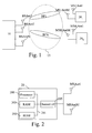
- Fig. 1 is a diagram representing the architecture of the wireless network according to present invention.
- At least one and preferably plural first telecommunication devices 20 l or 20 k are linked through a wireless network 15 to a second telecommunication device 10 using an uplink and a downlink channel.
- the second telecommunication device 10 is a base station or a node of the wireless network 15.
- the first telecommunication devices 20 l to 20 K are terminals like mobile phones, personal digital assistants, or personal computers.
- the telecommunication network 15 is a wireless telecommunication system which uses Time Division Duplexing scheme (TDD) or Frequency Division Duplexing scheme (FDD).
- TDD Time Division Duplexing scheme
- FDD Frequency Division Duplexing scheme
- the signals transferred in uplink and downlink channels are duplexed in different time periods in the same frequency band.
- the signals transferred within the wireless network 15 share the same frequency spectrum.
- the channel responses between the uplink and downlink channels of the telecommunication network 15 are reciprocal.
- Reciprocal means that if the downlink channel conditions are represented by a downlink matrix, the uplink channel conditions can be expressed by an uplink matrix which is the transpose of the downlink matrix.
- the signals transferred in uplink and downlink channels are duplexed in different frequency bands.
- the spectrum is divided into different frequency bands and the uplink and downlink signals are transmitted simultaneously.
- the channel responses between the uplink and downlink channels of the telecommunication network 15 are not perfectly reciprocal.
- the second telecommunication device 10 transfers simultaneously signals representatives of at most N groups of data or pilot signals to the first telecommunication devices 20 l to 20 k through the downlink channel and the first telecommunication devices 20 l to 20 k transfer signals to the second telecommunication device 10 through the uplink channel.
- the signals transferred by the first telecommunication devices 20 l to 20 K are signals representatives of a group of data or pilot signals.
- the pilot signals transferred by the first telecommunication devices 20 l to 20 k are multiplied by a downlink linear transform and preferably further weighted by a power coefficient determined from the downlink linear transform.
- the pilot signals transferred by the first telecommunication devices 20 l to 20 K are multiplied by an uplink linear transform and preferably further weighted by a power coefficient determined from the uplink linear transform.
- a group of data is as example a frame constituted at least by a header field and a payload field which comprises classical data like data related to a phone call, or a video transfer and so on.
- Pilot signals are predetermined sequences of symbols known by the telecommunication devices. Pilot signals are, as example and in a non limitative way, Walsh Hadamard sequences.
- the second telecommunication device 10 has N antennas noted BSAnt1 to BSAntN.
- the second telecommunication device 10 preferably controls the spatial direction of the signals transferred to each first telecommunication devices 20 1 to 20 K according to at least signals transferred by each first telecommunication devices 20 as it will be disclosed hereinafter.
- the second telecommunication device 10 transmits signals representatives of a group of data to a given first telecommunication device 20 k through the downlink channel, the signals are at most N times duplicated in order to perform beamforming, i.e. controls the spatial direction of the transmitted signals.
- the ellipse noted BF1 in the Fig. 1 shows the pattern of the radiated signals by the antennas BSAnt1 to BSAntN which are transferred to the first telecommunication device 20 1 by the second telecommunication device 10.
- the ellipse noted BFK in the Fig. 1 shows the pattern of the radiated signals by the antennas BSAnt1 to BSAntN which are transferred to the first telecommunication device 20 k by the second telecommunication device 10.
- Each first telecommunication device 20 1 to 20 k controls the spatial direction of the signals transferred to the second telecommunication device 10 by M k times duplicating the signals and weighting the duplicated signals by coefficients in order to perform beamforming, i.e. controls the spatial direction of the transmitted signals.
- the coefficients used for weighting the duplicated signals are transferred by the second telecommunication device 10.
- the ellipse noted BF1 in the Fig. 1 shows the pattern of the radiated signals by the antennas MS1 Ant1 to MS1AntM 1 which are transferred by the first telecommunication device 20 1 to the second telecommunication device 10.
- the ellipse noted BFK in the Fig. 1 shows the pattern of the radiated signals by the antennas MSKAntI to MSKAntM k which are transferred by the first telecommunication device 20 K to the second telecommunication device 10.
- Each first telecommunication device 20 k transfers, through its antennas MSkAnt1 to MSkAntM k , the signals to the second telecommunication device 10. More precisely, when the first telecommunication device 20 k transmits signals to the second telecommunication device 10 through the uplink channel, the signals are linear transformed in order to form M k signals from m 0 signals, with m 0 ⁇ M k , in order to use, as example, the propagation channels which have the highest complex propagation coefficients.
- the power of the pilot signals transferred by each first telecommunication device 20 k is adjusted according to the propagation coefficients measured on the downlink channel.
- the power of the signals representative of a group of data transferred by each first telecommunication device 20 k is adjusted according to a power information transferred by the second telecommunication device 10.
- Each first telecommunication device 20 k receives through the antennas MSkAnt1 to MSkAntM k , the signals transferred by the second telecommunication device 10. More precisely, when the first telecommunication device 20 k receives signals from the second telecommunication device 10 through the downlink channel, the M k received signals, after being weighted for beamforming purpose, are linear transformed in order to form m 0 signals, with m 0 ⁇ M k .
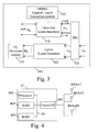
- Fig. 2 is a diagram representing the architecture of a first telecommunication device according to the present invention.
- the first telecommunication device 20 as example the first telecommunication device 20 k ,with k comprised between 1 and K , has, for example, an architecture based on components connected together by a bus 201 and a processor 200 controlled by programs related to the algorithms as disclosed in the Figs. 5 and/or 6.
- the first telecommunication device 20 is, in a variant, implemented under the form of one or several dedicated integrated circuits which execute the same operations as the one executed by the processor 200 as disclosed hereinafter.
- the bus 201 links the processor 200 to a read only memory ROM 202, a random access memory RAM 203 and a channel interface 205.
- the read only memory ROM 202 contains instructions of the programs related to the algorithms as disclosed in the Figs. 5 and/or 6 which are transferred, when the first telecommunication device 20 k is powered on to the random access memory RAM 203.
- the RAM memory 203 contains registers intended to receive variables, and the instructions of the programs related to the algorithm as disclosed in the Figs. 5 and/or 6.
- the channel interface 205 enables the transfer and/or of the reception of signals to and/or from the second telecommunication device 10.
- the channel interface 205 comprises means for directing the signals representatives of groups of data transferred by the first telecommunication device 20 k to the second telecommunication device 10, means for determining the propagation gains between the antennas of the first and second telecommunication devices in the downlink channel and/or in the uplink channel, means for multiplying the received signals by a downlink linear transform.
- the channel interface 205 comprises means for multiplying the transferred signals by an uplink linear transform.
- the channel interface 205 comprises means for multiplying the transferred pilot signals by a power coefficient determined by the first telecommunication device 20 k .
- the channel interface 205 comprises means for adjusting the power of the transferred signals representative of a group of data from a power information received from the second telecommunication device 10.
- the channel interface 205 will be described in detail in reference to the Fig. 3.
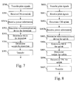
- Fig. 3 is a diagram representing the architecture of a channel interface of the first telecommunication device.
- the channel interface 205 comprises a MIMO channel matrix estimation module 350.
- the MIMO channel matrix estimation module 350 estimates the matrix H DL,k .
- the MIMO channel matrix estimation module 350 estimates also the matrix H UL,k which is the N*M k uplink MIMO channel matrix between the first telecommunication device 20 k and the second telecommunication device 10.
- the matrix H UL,k is equal to H T DL,k where [.] T denotes the transpose of [.] .
- the channel interface 205 comprises a downlink linear transform module 310 which comprises means for executing a linear transformation of the signal vector x k ( p ) using a m 0 * M k matrix V DL T .
- the downlink linear transform matrix V DL T is defined, as it will be disclosed hereinafter, so that the first telecommunication device 20 k has good channel conditions at the output x'(p).
- the downlink linear transform module 310 executes a linear transform on the signals received by the first telecommunication device.
- the downlink linear transform module 310 executes a linear transform on the m 0 pilot signals transferred by the first telecommunication device 20 k to the second telecommunication device 10 which comprise then a channel state information.
- the channel interface 205 comprises a transmit power control module 325 which multiplies the pilot signals to be transferred by a power coefficient determined by the first telecommunication device 20 k .
- the transmit power control module 325 adjusts the power of the transferred signals representative of a group of data from a power information received from the second telecommunication device 10.
- the uplink linear transform matrix V UL is defined so that good channel conditions are maintained between the first telecommunication device 20 k and the second telecommunication device 10.
- the uplink linear transform module 305 executes a linear transform on the signals representative of groups of data transferred by the first telecommunication device.
- the uplink linear transform module 305 executes a linear transform on the m 0 pilot signals transferred by the first telecommunication device 20 k to the second telecommunication device 10 which comprise then a channel state information.
- the channel interface 205 comprises an uplink direction control module 325 which controls the spatial direction of the signals transferred to the second telecommunication device 10 by M k times duplicating the signals and weighting the duplicated signals by coefficients in order to perform beamforming, i.e. controls the spatial direction of the transmitted signals.
- the coefficients used for weighting the duplicated signals are transferred by the second telecommunication device 10.
- Fig. 4 is a diagram representing the architecture of the second telecommunication device according to the present invention.
- the second telecommunication device 10 has, for example, an architecture based on components connected together by a bus 401 and a processor 400 controlled by programs related to the algorithms as disclosed in the Figs. 7 and/or 8.
- the second telecommunication device 10 is, in a variant, implemented under the form of one or several dedicated integrated circuits which execute the same operations as the one executed by the processor 400 as disclosed hereinafter.
- the bus 401 links the processor 400 to a read only memory ROM 402, a random access memory RAM 403 and a channel interface 405.
- the read only memory ROM 402 contains instructions of the programs related to the algorithms as disclosed in the Figs. 7 and/or 8 which are transferred, when the second telecommunication 10 is powered onto the random access memory RAM 403.
- the RAM memory 403 contains registers intended to receive variables, and the instructions of the programs related to the algorithms as disclosed in the Figs. 7 and/or 8.
- the processor 400 is able to determine, for each first telecommunication device 20 l to 20 K , from at least signals transferred by each first telecommunication device 20 l to 20 K , the modulation and coding scheme to be used by each first telecommunication device 20 k for receiving groups of data.
- the processor 400 is able to determine to which first telecommunication device 20, signals representative of a group of data have to be sent according to signals transferred by the first telecommunication devices 20.
- the processor 400 determines for each first telecommunication device 20 l to 20 k , from at least signals transferred by each first telecommunication device 20 k , the modulation and coding scheme to be used by each first telecommunication device 20 k for transferring groups of data or pilot signals and/or determines which first telecommunication device 20 has to transfer signals representative of a group of data to the second telecommunication devices 10.
- the processor 400 is also able to determine a power information which is representative of the transmission power to be used by each first telecommunication device 20 l to 20 k for transferring signals representative of a group of data from at least signals transferred by each first telecommunication device 20.
- the processor 400 is also able to determine from an information representative of a power coefficient received from each first telecommunication device, the power coefficient used by each first telecommunication device 20 1 to 20 K for multiplying the pilot signals transferred by each first telecommunication device 20 1 to 20 K .
- the processor 400 is also able to determine weighting coefficients for controlling the spatial direction of the signals transferred to each first telecommunication device 20 1 to 20 K in the downlink channel in order to perform beamforming.
- the processor 400 is also able to determine weighting coefficients for controlling the spatial direction of the signals transferred by each first telecommunication device 20 1 to 20 K in the uplink channel in order to perform beamforming.
- the channel interface 405 comprises a downlink direction control module, not shown in the Fig. 4, which controls the spatial direction of the signals transferred to each first telecommunication devices 20 l to 20 K by N times duplicating the signals and weighting the duplicated signals by coefficients in order to perform beamforming, i.e. controls the spatial direction of the transmitted signals.
- a downlink direction control module not shown in the Fig. 4, which controls the spatial direction of the signals transferred to each first telecommunication devices 20 l to 20 K by N times duplicating the signals and weighting the duplicated signals by coefficients in order to perform beamforming, i.e. controls the spatial direction of the transmitted signals.
- Fig. 5 is an algorithm executed by the first telecommunication device for the downlink channel according to the present invention.
- the present algorithm is executed by each first telecommunication device 20 l to 20 K , it will be disclosed when it is executed by the first telecommunication device 20 k .
- the MIMO channel matrix estimation module 350 estimates the matrix H DL,k from the received pilot signals.
- the MIMO channel matrix estimation module 350 estimates the interference plus noise components received by the first telecommunication device 20 k .
- step S502 is not executed.
- ⁇ [ û 1 ,...,û N ] is the N*N unitary matrix
- Q ⁇ [q ⁇ 1 ,..., q ⁇ Mk ] is the M k * M k unitary matrix
- the processor 200 selects m 0 singular-values with m 0 ⁇ M k . These m 0 singular-values are, as example, upper than a predetermined threshold or are the m 0 largest singular-values. As example, if the first telecommunication device 20k has three antennas, only the two largest singular-values are selected.
- the m 0 singular-values are selected from the downlink MIMO channel matrix H DL,k between the second telecommunication device 10 and the first telecommunication device 20 k .
- the processor 200 determines a downlink linear transform matrix V DL .
- V DL ⁇ e 1 ⁇ H DL , k * ⁇ H DL , k T ⁇ , ... e m ⁇ 0 ⁇ H DL , k * ⁇ H DL , k T ⁇ ⁇ , where e m ⁇ denotes the eigenvector of ⁇ corresponding to the m- th largest eigenvalue of ⁇ .
- the first telecommunication device 20 k determines V DL considering also the interference plus noise components received by the first telecommunication device 20 k .
- H DL,k,l denotes the downlink MIMO channel matrix between the second telecommunication device 10 and the first telecommunication device 20 k in the l -th frequency subband and E l [.] denotes the average of the L frequency subbands.
- the first telecommunication device 20 k determines V DL for each frequency subband or the first telecommunication device 20 k determines a unique matrix V DL for all the frequency subbands.
- V DL is given by: where ⁇ l denotes the interference plus noise correlation matrix in the l-th frequency subband determined by the first telecommunication device 20 k .
- V DL ⁇ D T ⁇ q 1 , ... , D T ⁇ q m ⁇ 0 ⁇ .
- V DL E ⁇ z k ′ p ⁇ z k ′ p H ⁇
- R E ⁇ V DL T ⁇ z k p ⁇ V DL T ⁇ z k p H ⁇
- R V DL T ⁇ ⁇ ⁇ V DL *
- R q 1 ... q m ⁇ 0 T D ⁇ ⁇ ⁇ D H q 1 * ... q m ⁇ 0 *
- the first telecommunication device 20 k whitens the interference plus noise components.
- the first telecommunication device 20 k needs to report only the virtual downlink MIMO channel matrix H ⁇ DL,K .
- the reporting of the interference correlation matrix R E ⁇ z k ⁇ p ⁇ z k ⁇ ( p ⁇ ) H ⁇ , which can be obtained by averaging a plurality of samples, is no more required.
- H UL,k is the N*M k uplink MIMO channel matrix between the first telecommunication device 20 k and the second telecommunication device 10.
- the processor 200 moves from step S505 to step S505b. In a variant, the processor 200 moves from step S505 to step S506.
- the processor 200 determines a power coefficient which multiplies the pilot signals to be transferred on the uplink channel.
- the power coefficient is dependant from the downlink channel matrix H DL,k .
- the processor 200 transfers the determined matrix V DL to the downlink linear transform module 310 which uses the determined matrix V DL for executing a linear transformation of the signal vector x k (p) using a m 0 * M k matrix V DL T .
- the processor 200 transfers, at the same step, the power coefficient determined at step S505b to the transmit power control module 325 of the channel interface 205.
- the processor 200 determines the channel state information on the downlink channel considering x'(p).
- the channel state information is the m 0 * N virtual downlink MIMO channel matrix H ⁇ DL,k .
- the matrix H ⁇ DL,k is preferably determined using downlink pilot signals which are transferred by the second telecommunication device 10.
- the interference correlation matrix is determined by averaging z k ( p )'z k ( p )' over a plurality of samples.
- the channel state information are the m 0 * N virtual downlink MIMO channel matrix H ⁇ DL,k and an approximated interference plus noise power per antenna P ' z determined at the output x '( p ).
- the interference plus noise power per antenna P ' z is determined by averaging Z k (p)' H Z k ( p )' over a plurality of samples.
- the channel state information are the m 0 *N matrix R -1 / 2 H ⁇ DL,k .
- the matrix R - 1/2 H ⁇ DL,k expresses the channel conditions after an interference whitening process executed by the first telecommunication device 20 k .
- the channel state information are the m 0 * N matrix P z ' - 1/2 H ⁇ DL,k .
- the matrix P z ' - 1/2 H ⁇ DL,k expresses an approximation of the channel conditions after a conversion of the interference plus noise power into unit power at the output x'( p ).
- the channel state information is representative of the virtual downlink MIMO channel matrix H ⁇ DL , k and the interference correlation matrix R .
- the processor 200 commands the transfer, to the second telecommunication device 10, of the determined channel state information through the uplink channel.
- the channel state information is reported by transferring m 0 pilot signals which are multiplied by the downlink linear transform matrix V DL .
- the channel state information can also be reported under the form of information bits.
- the processor 200 moves from step S508 to step S508b. In a variant, the processor 200 moves from step S508 to step S509.
- the processor 200 commands the transfer of the information representative of the coefficient determined at step S505b to the second telecommunication device 10.
- the second telecommunication device 10 can estimate H ⁇ DL,k .
- the second telecommunication device 10 can't estimate H ⁇ DL,k as far as the power of the pilot signals is undefined.
- the first telecommunication device 20 k has to send the information representative of the power coefficient to the second telecommunication device 10.
- the processor 200 detects the reception through the channel interface 205, of information representative of the modulation and coding scheme determined by the second telecommunication device 10. Such information indicates the modulation and the coding scheme the first telecommunication device 20 k has to use when it receives groups of data through the downlink channel.
- the processor 200 transfers the parameters related to the modulation and coding scheme to the channel interface 205 which uses the parameters for receiving groups of information.
- the processor 200 returns then to step S500.
- Fig. 6 is an algorithm executed by the first telecommunication device for the uplink channel according to the present invention.
- the present algorithm is executed by each first telecommunication device 20 1 to 20 K , it will be disclosed when it is executed by the first telecommunication device 20 k .
- the MIMO channel matrix estimation module 350 estimates the uplink channel matrix H UL , K .
- H UL , k H DL , k T as the channel responses between the uplink and downlink channels of the telecommunication network 15 are reciprocal.
- the MIMO channel matrix estimation module 350 determines the interference plus noise components received by the first telecommunication device 20 k .
- step S602 is not executed.
- U u [ u U 1 ,... u UN ] is the N * N unitary matrix
- Q U [ q U 1 ,... q UMk ] is the M k * M k unitary matrix
- the processor 200 selects m 0 singular-values. These m 0 singular-values are as example upper than a predetermined threshold or are the m 0 largest singular-values.
- the number m 0 of singular-values selected for the uplink channel can be equal or different to the number m 0 of singular-values selected for the downlink channel.
- the m 0 singular-values are selected from the uplink MIMO channel matrix H UL,k between the first telecommunication device 20 k and the second telecommunication device 10.
- step S605 the processor 200 determines a linear transform matrix V UL .
- V UL ⁇ e 1 ⁇ H UL , k H ⁇ H UL , k ⁇ , ... e m ⁇ 0 ⁇ H UL , k H ⁇ H UL , k ⁇ ⁇ , where e m ⁇ denotes the eigenvector of ⁇ corresponding to the m -th largest eigenvalue of ⁇ .
- the first telecommunication device 20 k determines V UL considering also the interference plus noise components received by the first telecommunication device 20 k .
- H UL,k,l is the uplink MIMO channel matrix between the second telecommunication device 10 and the first telecommunication device 20 k in the l -th frequency subband and E l [.] denotes the average of the L frequency subbands.
- the first telecommunication device 20 k determines V UL considering also the interference plus noise components received by the first telecommunication device 20 k .
- the first telecommunication device 20 k needs only to report m 0 weighted pilot signals which are use by the second telecommunication device 10 in order to determine the channel quality indication for the uplink and downlink channels.
- the processor 200 moves from step S605 to step S605b. In a variant, the processor 200 moves from step S605 to step S606.
- the processor 200 determines a power coefficient which multiplies the pilot signals to be transferred on the uplink channel.
- the power coefficient is dependant from the uplink channel matrix H UL,k .
- the processor 200 transfers, at the same step, the power coefficient determined at step S605b to the transmit power control module 325 of the channel interface 205.
- the processor 200 commands the transfer of m 0 pilot signals composed of p 0 symbols r' (1), ...r' ( p 0 ) to the second telecommunication device 10 through the channel interface 205.
- the processor 200 moves from step S607 to step S607b. In a variant, the processor 200 moves from step S607 to step S608.
- the processor 200 commands the transfer of an information representative of the power coefficient determined at step S605b to the second telecommunication device 10.
- the processor 200 detects, through the channel interface 205, the reception of a group of data which comprises the modulation and coding scheme which has to be used for transferring groups of data through the uplink channel.
- the processor 200 detects also, the reception of a group of data which comprises a request of an update of the transmit power of the signals representative of a group or groups of data it transfers through the uplink channel.
- the request of an update of the transmit power comprises an information representative of an increase or a decrease command of the transmit power of signals representative of a group of data.
- the coefficients used for weighting the signals transferred in the uplink channel in order to perform beamforming are also received from the second telecommunication device 10 at step S608.
- the processor 200 commands the transfer of the received modulation and coding scheme and the received coefficients which have to be used by the channel interface 205 for transferring groups of data through the uplink channel.
- the processor 200 adjusts the transmit power coefficient. If the information is representative of an increase, the processor 200 increases the transmit power coefficient by one decibel, if the information is representative of a decrease, the processor 200 decreases the transmit power coefficient by one decibel and transfers the adjusted transmit power coefficient to the transmit power control module 325 of the channel interface 205.
- the virtual control of the transmission is then performed on the virtual uplink MIMO channel.
- the processor 200 returns then to step S600.
- Fig. 7 is an algorithm executed by the second telecommunication device for determining, from channel state information on downlink channels, the first telecommunication device which has to transfer at least one group of data and/or how to transfer at least one group of data on the downlink channel, according to the present invention.
- the processor 400 detects the reception of the channel state information transferred by at least a part of the first telecommunication devices 20 at step S508 of the algorithm of the Fig. 5.
- the channel state information is preferably received under the form of pilot signals.
- the processor 400 moves from step S701 to step S701b. In a variant, the processor 400 moves from step S701 to step S702.
- the processor 400 detects the reception of an information representative of a power coefficient used by the first telecommunication device 20 k for weighting pilot signals received at step S701.
- the second telecommunication device 10 receives the channel state information transferred by each first telecommunication 20 1 to 20 K and determines for each first telecommunication device 20 1 to 20 K , information like the modulation and coding scheme to be used by the first telecommunication devices 20 and by the second telecommunication device 10 for the downlink channel.
- the second telecommunication device 10 determines, from the channel state information, the coefficients to be used for weighting the signals transferred in the downlink channel in order to perform beamforming.
- the second telecommunication device 10 determines these information considering the m 0 * N virtual downlink MIMO channel matrix H ⁇ DL,k and the an approximated interference plus noise power per antenna P ' z .
- the second telecommunication device 10 determines these information considering the matrix R - 1/ 2 H ⁇ DL,k which expresses the channel conditions after an interference whitening process.
- the second telecommunication device 10 determines these information considering the m 0 * N matrix P z ' - 1/2 H ⁇ DL,k which expresses an approximation of the channel conditions after a conversion of the interference plus noise power into unit power at the output x'(p).
- the second telecommunication device 10 determines these information using the channel response of the m 0 pilot signals received on the uplink channel.
- the channel response of the m 0 pilot signals are representative of the virtual downlink MIMO channel matrix H ⁇ DL,k and the interference correlation matrix R .
- the processor 400 determines the coefficients to be used by the second telecommunication device for weighting the transferred signals in order to perform beamforming on the transferred signals and the transmission power to be used for transferring at least a group of data to the first telecommunication device.
- the processor 400 commands the transfer of the determined modulation, coding scheme and the determined coefficients to the channel interface 405.
- the channel interface 405 uses the determined modulation and coding scheme, and the determined coefficients for the transfer of group of data through the downlink channel.
- the channel interface 405 transfers also the modulation, coding scheme to the concerned first telecommunication device 20 k .
- the command which is representative of an increase or a decrease of the transmit power of the first telecommunication device 20 k is also transferred at the same step.
- the processor 400 returns then to step S700.
- Fig. 8 is an algorithm executed by the second telecommunication device for determining, from channel state information on uplink channels, the first telecommunication device which has to transfer at least one group of data and how to transfer the at least one group of data on the uplink channel according to the present invention.
- each first telecommunication device 20 l to 20 K transmits the p -th symbol under the form of M k simultaneous signals r 1 ( p ) ,...,r M k (p) through its M k antennas MSAnt1 to MSAntK to the second telecommunication device 10 on the uplink channel
- the processor 400 detects the reception of the m 0 pilot signals composed of p 0 symbols r '(1), .... r '( p 0 ) transferred by at least a part of the first telecommunication devices 20 at step S607 of the algorithm of the Fig. 6.
- the processor 400 determines the channel state information from the received pilot signals.
- the received signals at the second telecommunication device 10 are expressed as
- the processor 400 determines the channel state information on the uplink channel.
- the processor 400 moves from step S802 to step S802b. In a variant, the processor 400 moves from step S802 to step S803.
- the processor 400 detects the reception of an information representative of a power coefficient used by the first telecommunication device 20 k for multiplying the pilot signals received at step S801.
- the processor 400 uses the matrix H UL,k V UL , determines the transmission control, i.e. the weighting coefficients to be used by the first telecommunication device in order to perform beamforming for the uplink channel.
- the processor 400 determines the transmission control, i.e. the weighting coefficients to be used by the first telecommunication device in order to perform beamforming for the uplink channel.
- the processor 400 moves from step S805 to S807.
- the processor 400 moves from step S805 to S806.
- the processor 400 determines the power of the signals that the first telecommunication device 20 k has to use when it transfers signals representative of groups of data to the second telecommunication device 10 through the uplink channel.
- the channel interface 405 measures the power level of m 0 received pilot signals from the first telecommunication device 20 k and transfers it to the processor 400.
- the processor 400 checks if the measured power level is upper or lower than a predetermined range of power. If the measured power is lower than a predetermined range of power the processor 400 forms a command which is representative of an increase, as example of one decibel, of the transmit power of the first telecommunication device 20 k . If the information is representative of an decrease, the processor 400 forms a command which is representative of a decrease, as example of one decibel, of the transmit power of the first telecommunication device 20 k .
- the processor 400 commands the transfer to the determined first telecommunication device 20 k of the determined modulation and coding scheme to the channel interface 405 and/or the determined transmit power at step S806 and/or the weighting coefficients to be used by the first telecommunication device in order to perform beamforming for the uplink channel.
- the channel interface 405 uses the determined modulation and coding scheme for the reception of group of data through the uplink channel and.
- the channel interface 405 transfers the modulation and coding scheme to the concerned first telecommunication device 20 k and/or, if needed, of the command which is representative of an increase or a decrease of the transmit power of the first telecommunication device 20 k and/or of the weighting coefficients to be used by the first telecommunication device in order to perform beamforming for the uplink channel.
- the processor 400 returns then to step S800.
- the first telecommunication device 20 k determines the propagation gains between the antennas of the first and second telecommunication devices as it has already been described.
- the first telecommunication device 20 k forms, for each of the first telecommunication device's antenna, a group propagation gains and determines among the groups, the ones which have the highest norm.
- the first telecommunication device selects among the determined propagation gains the group or groups which has or have the highest norm, as the subset of the determined propagation gains.
- the first telecommunication device 20 k selects m 0 antennas among its M k antennas which have the m 0 largest values ⁇ h m ⁇ among ⁇ h 1 ⁇ ,..., ⁇ h Mk ⁇ .
- V DL 1 0 0 0 0 1 0 0 0 0 .
- V DL T ⁇ H DL , k h 1 h 3 .
- the virtual MIMO downlink channel comprises only the highest propagation gains ⁇ h 1 ⁇ and ⁇ h 3 ⁇ .
Landscapes
- Engineering & Computer Science (AREA)
- Computer Networks & Wireless Communication (AREA)
- Signal Processing (AREA)
- Quality & Reliability (AREA)
- Power Engineering (AREA)
- Mobile Radio Communication Systems (AREA)
- Radio Transmission System (AREA)
Priority Applications (4)
| Application Number | Priority Date | Filing Date | Title |
|---|---|---|---|
| EP06291045A EP1871017A1 (fr) | 2006-06-23 | 2006-06-23 | Procédé et appareil pour rapporter via un réseau sans fil l'information de l'état du canal entre un premier appareil de télécommunication et un second appareil de télécommunication |
| JP2007164264A JP2008035497A (ja) | 2006-06-23 | 2007-06-21 | チャネル状態情報を報告するための方法及びデバイス、転送を制御するためのシステム、コンピュータプログラム、並びに信号 |
| US11/767,186 US20090010148A1 (en) | 2006-06-23 | 2007-06-22 | Method and device for reporting, through a wireless network, a channel state information between a first telecommunication device and a second telecommunication device |
| US12/869,543 US20100322101A1 (en) | 2006-06-23 | 2010-08-26 | Method and device for reporting, through a wireless network, a channel state information between a first telecommunication device and a second telecommunication device |
Applications Claiming Priority (1)
| Application Number | Priority Date | Filing Date | Title |
|---|---|---|---|
| EP06291045A EP1871017A1 (fr) | 2006-06-23 | 2006-06-23 | Procédé et appareil pour rapporter via un réseau sans fil l'information de l'état du canal entre un premier appareil de télécommunication et un second appareil de télécommunication |
Publications (1)
| Publication Number | Publication Date |
|---|---|
| EP1871017A1 true EP1871017A1 (fr) | 2007-12-26 |
Family
ID=37434233
Family Applications (1)
| Application Number | Title | Priority Date | Filing Date |
|---|---|---|---|
| EP06291045A Withdrawn EP1871017A1 (fr) | 2006-06-23 | 2006-06-23 | Procédé et appareil pour rapporter via un réseau sans fil l'information de l'état du canal entre un premier appareil de télécommunication et un second appareil de télécommunication |
Country Status (3)
| Country | Link |
|---|---|
| US (2) | US20090010148A1 (fr) |
| EP (1) | EP1871017A1 (fr) |
| JP (1) | JP2008035497A (fr) |
Cited By (1)
| Publication number | Priority date | Publication date | Assignee | Title |
|---|---|---|---|---|
| WO2009128767A1 (fr) * | 2008-04-18 | 2009-10-22 | Telefonaktiebolaget L M Ericsson (Publ) | Procédé de précodage lent mimo et appareil |
Families Citing this family (7)
| Publication number | Priority date | Publication date | Assignee | Title |
|---|---|---|---|---|
| KR100869070B1 (ko) * | 2006-10-16 | 2008-11-17 | 삼성전자주식회사 | 다중 입력 다중 출력 시스템의 빔 형성 장치 및 방법 |
| CN101557246B (zh) * | 2008-04-07 | 2012-10-03 | 中国移动通信集团公司 | 一种上行功率控制方法及装置 |
| US8185146B2 (en) * | 2009-07-24 | 2012-05-22 | Clearwire Ip Holdings Llc | Quality of service based downlink power allocation |
| KR101449443B1 (ko) * | 2009-08-17 | 2014-10-13 | 알까뗄 루슨트 | 통신 네트워크에서 프리코딩 채널 코히어런시 유지 방법 및 장치 |
| WO2011072305A1 (fr) * | 2009-12-11 | 2011-06-16 | Maxlinear, Inc. | Diversité à faible complexité utilisant une pré-égalisation |
| EP2777190B1 (fr) * | 2011-11-08 | 2017-10-11 | Marvell World Trade Ltd. | Procédé et appareil pour atténuation des interférences connues |
| KR20220111145A (ko) * | 2021-02-01 | 2022-08-09 | 삼성전자주식회사 | 간섭 백색화 동작을 수행하는 무선 통신 장치 및 이의 동작 방법 |
Family Cites Families (11)
| Publication number | Priority date | Publication date | Assignee | Title |
|---|---|---|---|---|
| US6584302B1 (en) * | 1999-10-19 | 2003-06-24 | Nokia Corporation | Method and arrangement for forming a beam |
| US6473467B1 (en) * | 2000-03-22 | 2002-10-29 | Qualcomm Incorporated | Method and apparatus for measuring reporting channel state information in a high efficiency, high performance communications system |
| US7039363B1 (en) * | 2001-09-28 | 2006-05-02 | Arraycomm Llc | Adaptive antenna array with programmable sensitivity |
| KR100795824B1 (ko) * | 2001-12-08 | 2008-01-17 | 주식회사 세스텍 | 안테나 어레이를 구비한 통신시스템에서 다이버시티이득을 얻기 위한 신호 처리 방법 및 장치 |
| US7362830B2 (en) * | 2002-12-31 | 2008-04-22 | Lg Electronics Inc. | Smart antenna system and method |
| US7457590B2 (en) * | 2003-12-23 | 2008-11-25 | Motorola, Inc. | Method, apparatus and system for use in the transmission of wireless communications using multiple antennas |
| JP4474934B2 (ja) * | 2004-02-18 | 2010-06-09 | ソニー株式会社 | 無線通信システム、無線通信装置及び無線通信方法、並びにコンピュータ・プログラム |
| US7564814B2 (en) * | 2004-05-07 | 2009-07-21 | Qualcomm, Incorporated | Transmission mode and rate selection for a wireless communication system |
| JPWO2006011345A1 (ja) * | 2004-07-29 | 2008-05-01 | 松下電器産業株式会社 | 無線通信装置及び無線通信方法 |
| EP1804409B1 (fr) * | 2005-12-27 | 2011-09-07 | Mitsubishi Electric R&D Centre Europe B.V. | Procédé et dispositif pour rapporter à un deuxième dispositif de télécommunication des informations associées à composantes d'interférence reçues par un premier dispositif de télécommunication en certains sous-bandes de fréquence |
| US8000418B2 (en) * | 2006-08-10 | 2011-08-16 | Cisco Technology, Inc. | Method and system for improving robustness of interference nulling for antenna arrays |
-
2006
- 2006-06-23 EP EP06291045A patent/EP1871017A1/fr not_active Withdrawn
-
2007
- 2007-06-21 JP JP2007164264A patent/JP2008035497A/ja active Pending
- 2007-06-22 US US11/767,186 patent/US20090010148A1/en not_active Abandoned
-
2010
- 2010-08-26 US US12/869,543 patent/US20100322101A1/en not_active Abandoned
Non-Patent Citations (2)
| Title |
|---|
| PANDE T ET AL: "A weighted least squares approach to precoding with pilots for MIMO-OFDM", IEEE TRANSACTIONS ON SIGNAL PROCESSING IEEE USA, vol. 54, no. 10, 1 October 2006 (2006-10-01), GB, pages 4067 - 4073, XP002409775, ISSN: 1053-587X * |
| SANAYEI S ET AL: "On the design of linear precoders for orthogonal space-time block codes with limited feedback", WIRELESS COMMUNICATIONS AND NETWORKING CONFERENCE, 2005 IEEE NEW ORLEANS, LA, USA 13-17 MARCH 2005, PISCATAWAY, NJ, USA,IEEE, 13 March 2005 (2005-03-13), pages 489 - 493, XP010791212, ISBN: 0-7803-8966-2 * |
Cited By (3)
| Publication number | Priority date | Publication date | Assignee | Title |
|---|---|---|---|---|
| WO2009128767A1 (fr) * | 2008-04-18 | 2009-10-22 | Telefonaktiebolaget L M Ericsson (Publ) | Procédé de précodage lent mimo et appareil |
| CN102007739A (zh) * | 2008-04-18 | 2011-04-06 | 爱立信电话股份有限公司 | Mimo慢预编码方法和装置 |
| CN102007739B (zh) * | 2008-04-18 | 2015-01-28 | 爱立信电话股份有限公司 | Mimo慢预编码方法和装置 |
Also Published As
| Publication number | Publication date |
|---|---|
| US20090010148A1 (en) | 2009-01-08 |
| JP2008035497A (ja) | 2008-02-14 |
| US20100322101A1 (en) | 2010-12-23 |
Similar Documents
| Publication | Publication Date | Title |
|---|---|---|
| US7139328B2 (en) | Method and apparatus for closed loop data transmission | |
| US7113808B2 (en) | Apparatus and method for transmitting and receiving signals using multi-antennas | |
| US7872963B2 (en) | MIMO-OFDM system using eigenbeamforming method | |
| US6927728B2 (en) | Method and apparatus for multi-antenna transmission | |
| KR101507088B1 (ko) | 다중 입출력 무선통신 시스템에서 상향링크 빔 성형 및 공간분할 다중 접속 장치 및 방법 | |
| KR101408938B1 (ko) | 다중 입출력 무선통신 시스템에서 일반화된 아이겐 분석을이용한 빔포밍 장치 및 방법 | |
| KR101088643B1 (ko) | 가변 슬롯 구조를 갖는 mimo 통신 시스템 | |
| EP1871017A1 (fr) | Procédé et appareil pour rapporter via un réseau sans fil l'information de l'état du canal entre un premier appareil de télécommunication et un second appareil de télécommunication | |
| US20040235433A1 (en) | Determining transmit diversity order and branches | |
| EP1804409B1 (fr) | Procédé et dispositif pour rapporter à un deuxième dispositif de télécommunication des informations associées à composantes d'interférence reçues par un premier dispositif de télécommunication en certains sous-bandes de fréquence | |
| US9008008B2 (en) | Method for communicating in a MIMO context | |
| US7778605B2 (en) | Method and device for reporting information related to interference components received by a first telecommunication device to a second telecommunication device | |
| US20120057645A1 (en) | method for communicating in a network | |
| KR20080073191A (ko) | 무선 통신 시스템에서 채널 사운딩 신호 전송 장치 및 방법 | |
| EP1871023B1 (fr) | Procédé et dispositif pour déterminer des informations d'etat du canal à transmettre d'un premier à un deuxième dispositif de télécommunication | |
| CN101577573B (zh) | 独立数据流控制方法及装置 | |
| EP1780907B1 (fr) | Procédé de contrôle de la transmission de signaux | |
| EP2008381B1 (fr) | Procede pour transferer des informations de puissance utilisees par un dispositif de telecommunications pour ponderer au moins un signal pilote | |
| JP4260653B2 (ja) | 空間多重伝送用送信装置 |
Legal Events
| Date | Code | Title | Description |
|---|---|---|---|
| PUAI | Public reference made under article 153(3) epc to a published international application that has entered the european phase |
Free format text: ORIGINAL CODE: 0009012 |
|
| AK | Designated contracting states |
Kind code of ref document: A1 Designated state(s): AT BE BG CH CY CZ DE DK EE ES FI FR GB GR HU IE IS IT LI LT LU LV MC NL PL PT RO SE SI SK TR |
|
| AX | Request for extension of the european patent |
Extension state: AL BA HR MK YU |
|
| 17P | Request for examination filed |
Effective date: 20080211 |
|
| 17Q | First examination report despatched |
Effective date: 20080507 |
|
| AKX | Designation fees paid |
Designated state(s): AT BE BG CH CY CZ DE DK EE ES FI FR GB GR HU IE IS IT LI LT LU LV MC NL PL PT RO SE SI SK TR |
|
| RAP1 | Party data changed (applicant data changed or rights of an application transferred) |
Owner name: MITSUBISHI DENKI KABUSHIKI KAISHA Owner name: MITSUBISHI ELECTRIC R&D CENTRE EUROPE B.V. |
|
| RIC1 | Information provided on ipc code assigned before grant |
Ipc: H04B 7/06 20060101ALI20141124BHEP Ipc: H04L 25/03 20060101ALI20141124BHEP Ipc: H04L 1/00 20060101AFI20141124BHEP Ipc: H04L 25/02 20060101ALI20141124BHEP Ipc: H04L 1/06 20060101ALI20141124BHEP |
|
| STAA | Information on the status of an ep patent application or granted ep patent |
Free format text: STATUS: THE APPLICATION IS DEEMED TO BE WITHDRAWN |
|
| 18D | Application deemed to be withdrawn |
Effective date: 20150106 |