EP1870267A1 - Buchse mit Sensoreinrichtung - Google Patents
Buchse mit Sensoreinrichtung Download PDFInfo
- Publication number
- EP1870267A1 EP1870267A1 EP07011558A EP07011558A EP1870267A1 EP 1870267 A1 EP1870267 A1 EP 1870267A1 EP 07011558 A EP07011558 A EP 07011558A EP 07011558 A EP07011558 A EP 07011558A EP 1870267 A1 EP1870267 A1 EP 1870267A1
- Authority
- EP
- European Patent Office
- Prior art keywords
- sleeve
- outer sleeve
- inner sleeve
- sensor electrode
- bushing
- Prior art date
- Legal status (The legal status is an assumption and is not a legal conclusion. Google has not performed a legal analysis and makes no representation as to the accuracy of the status listed.)
- Granted
Links
- 230000033001 locomotion Effects 0.000 claims abstract description 42
- 239000004020 conductor Substances 0.000 claims abstract description 23
- 239000003990 capacitor Substances 0.000 claims description 47
- 239000012528 membrane Substances 0.000 claims description 24
- 238000007789 sealing Methods 0.000 claims description 17
- 229920001971 elastomer Polymers 0.000 abstract description 11
- 239000005060 rubber Substances 0.000 abstract description 6
- 239000000806 elastomer Substances 0.000 description 5
- 239000000463 material Substances 0.000 description 5
- 229920006267 polyester film Polymers 0.000 description 5
- 238000006073 displacement reaction Methods 0.000 description 4
- 239000004033 plastic Substances 0.000 description 4
- 229920003023 plastic Polymers 0.000 description 4
- 239000000725 suspension Substances 0.000 description 4
- 238000005259 measurement Methods 0.000 description 3
- 239000000969 carrier Substances 0.000 description 2
- 238000011109 contamination Methods 0.000 description 2
- 238000011161 development Methods 0.000 description 2
- 230000018109 developmental process Effects 0.000 description 2
- 239000004744 fabric Substances 0.000 description 2
- 239000011888 foil Substances 0.000 description 2
- 239000002245 particle Substances 0.000 description 2
- 229920000728 polyester Polymers 0.000 description 2
- 239000004814 polyurethane Substances 0.000 description 2
- 230000002787 reinforcement Effects 0.000 description 2
- 239000000126 substance Substances 0.000 description 2
- 229920002725 thermoplastic elastomer Polymers 0.000 description 2
- 229910000831 Steel Inorganic materials 0.000 description 1
- 230000003044 adaptive effect Effects 0.000 description 1
- 230000015572 biosynthetic process Effects 0.000 description 1
- 239000002131 composite material Substances 0.000 description 1
- 230000006835 compression Effects 0.000 description 1
- 238000007906 compression Methods 0.000 description 1
- 239000000356 contaminant Substances 0.000 description 1
- 238000001514 detection method Methods 0.000 description 1
- 239000003989 dielectric material Substances 0.000 description 1
- 230000000694 effects Effects 0.000 description 1
- 239000013536 elastomeric material Substances 0.000 description 1
- 230000007613 environmental effect Effects 0.000 description 1
- 238000005530 etching Methods 0.000 description 1
- 230000002349 favourable effect Effects 0.000 description 1
- 230000006698 induction Effects 0.000 description 1
- 230000001939 inductive effect Effects 0.000 description 1
- 238000003475 lamination Methods 0.000 description 1
- 239000002184 metal Substances 0.000 description 1
- 238000000034 method Methods 0.000 description 1
- 239000010705 motor oil Substances 0.000 description 1
- 239000003921 oil Substances 0.000 description 1
- 230000000149 penetrating effect Effects 0.000 description 1
- 229920001296 polysiloxane Polymers 0.000 description 1
- 229920002635 polyurethane Polymers 0.000 description 1
- 229920003225 polyurethane elastomer Polymers 0.000 description 1
- 230000003014 reinforcing effect Effects 0.000 description 1
- 229920002379 silicone rubber Polymers 0.000 description 1
- 230000006641 stabilisation Effects 0.000 description 1
- 238000011105 stabilization Methods 0.000 description 1
- 239000010959 steel Substances 0.000 description 1
- 229920001169 thermoplastic Polymers 0.000 description 1
- 239000004416 thermosoftening plastic Substances 0.000 description 1
- 238000004073 vulcanization Methods 0.000 description 1
Images




Classifications
-
- B—PERFORMING OPERATIONS; TRANSPORTING
- B60—VEHICLES IN GENERAL
- B60G—VEHICLE SUSPENSION ARRANGEMENTS
- B60G17/00—Resilient suspensions having means for adjusting the spring or vibration-damper characteristics, for regulating the distance between a supporting surface and a sprung part of vehicle or for locking suspension during use to meet varying vehicular or surface conditions, e.g. due to speed or load
- B60G17/015—Resilient suspensions having means for adjusting the spring or vibration-damper characteristics, for regulating the distance between a supporting surface and a sprung part of vehicle or for locking suspension during use to meet varying vehicular or surface conditions, e.g. due to speed or load the regulating means comprising electric or electronic elements
- B60G17/0195—Resilient suspensions having means for adjusting the spring or vibration-damper characteristics, for regulating the distance between a supporting surface and a sprung part of vehicle or for locking suspension during use to meet varying vehicular or surface conditions, e.g. due to speed or load the regulating means comprising electric or electronic elements characterised by the regulation being combined with other vehicle control systems
-
- F—MECHANICAL ENGINEERING; LIGHTING; HEATING; WEAPONS; BLASTING
- F16—ENGINEERING ELEMENTS AND UNITS; GENERAL MEASURES FOR PRODUCING AND MAINTAINING EFFECTIVE FUNCTIONING OF MACHINES OR INSTALLATIONS; THERMAL INSULATION IN GENERAL
- F16F—SPRINGS; SHOCK-ABSORBERS; MEANS FOR DAMPING VIBRATION
- F16F1/00—Springs
- F16F1/36—Springs made of rubber or other material having high internal friction, e.g. thermoplastic elastomers
- F16F1/38—Springs made of rubber or other material having high internal friction, e.g. thermoplastic elastomers with a sleeve of elastic material between a rigid outer sleeve and a rigid inner sleeve or pin, i.e. bushing-type
-
- G—PHYSICS
- G01—MEASURING; TESTING
- G01D—MEASURING NOT SPECIALLY ADAPTED FOR A SPECIFIC VARIABLE; ARRANGEMENTS FOR MEASURING TWO OR MORE VARIABLES NOT COVERED IN A SINGLE OTHER SUBCLASS; TARIFF METERING APPARATUS; MEASURING OR TESTING NOT OTHERWISE PROVIDED FOR
- G01D5/00—Mechanical means for transferring the output of a sensing member; Means for converting the output of a sensing member to another variable where the form or nature of the sensing member does not constrain the means for converting; Transducers not specially adapted for a specific variable
- G01D5/12—Mechanical means for transferring the output of a sensing member; Means for converting the output of a sensing member to another variable where the form or nature of the sensing member does not constrain the means for converting; Transducers not specially adapted for a specific variable using electric or magnetic means
- G01D5/14—Mechanical means for transferring the output of a sensing member; Means for converting the output of a sensing member to another variable where the form or nature of the sensing member does not constrain the means for converting; Transducers not specially adapted for a specific variable using electric or magnetic means influencing the magnitude of a current or voltage
- G01D5/24—Mechanical means for transferring the output of a sensing member; Means for converting the output of a sensing member to another variable where the form or nature of the sensing member does not constrain the means for converting; Transducers not specially adapted for a specific variable using electric or magnetic means influencing the magnitude of a current or voltage by varying capacitance
- G01D5/241—Mechanical means for transferring the output of a sensing member; Means for converting the output of a sensing member to another variable where the form or nature of the sensing member does not constrain the means for converting; Transducers not specially adapted for a specific variable using electric or magnetic means influencing the magnitude of a current or voltage by varying capacitance by relative movement of capacitor electrodes
- G01D5/2412—Mechanical means for transferring the output of a sensing member; Means for converting the output of a sensing member to another variable where the form or nature of the sensing member does not constrain the means for converting; Transducers not specially adapted for a specific variable using electric or magnetic means influencing the magnitude of a current or voltage by varying capacitance by relative movement of capacitor electrodes by varying overlap
-
- F—MECHANICAL ENGINEERING; LIGHTING; HEATING; WEAPONS; BLASTING
- F16—ENGINEERING ELEMENTS AND UNITS; GENERAL MEASURES FOR PRODUCING AND MAINTAINING EFFECTIVE FUNCTIONING OF MACHINES OR INSTALLATIONS; THERMAL INSULATION IN GENERAL
- F16F—SPRINGS; SHOCK-ABSORBERS; MEANS FOR DAMPING VIBRATION
- F16F2230/00—Purpose; Design features
- F16F2230/08—Sensor arrangement
Definitions
- the invention relates to a bush, comprising a sensor device, an inner sleeve and an outer sleeve surrounding it, wherein between the inner sleeve and outer sleeve, an elastic medium is arranged, which counteracts a movement of the inner sleeve relative to the outer sleeve and wherein the sensor device detects the movement.
- Such sockets are already known from the prior art. They are used in motor vehicle chassis. The use of these jacks, for example, allows tracking or adjustment of headlight positions. In particular, the headlights of a loaded vehicle can be readjusted in such a way that its emission characteristic corresponds to that of an unloaded vehicle.
- Such a socket can also serve for the level control of air suspension vehicles, or provide signals for an adaptive suspension control.
- the generic sockets are positioned in the chassis of motor vehicles.
- a sleeve of the socket is the chassis and another sleeve of the sleeve assigned to a wheel or an axle part.
- an angle between the axle part and the chassis is established which corresponds to a twist angle of the inner sleeve relative to the outer sleeve of the bushing.
- This angle of rotation can be detected and processed by a downstream electronic device.
- the electronic device can then send signals to the headlights of the motor vehicle, which cause readjustment of the headlight positions.
- the signals can also open valves of a level control. In the case of a chassis control, actuating currents are switched to a damper valve.
- the invention is therefore based on the object to design a socket of the type mentioned and further, that the most accurate detection of the rotation angle of the inner sleeve is ensured relative to the outer sleeve.
- a socket of the type mentioned above is characterized in that the sensor device comprises means which movements of the inner sleeve relative to the outer sleeve at least partially compensate, which are superimposed on a torsional movement of the inner sleeve relative to the outer sleeve.
- the means could be associated with first and second sensor electrodes, wherein a sensor electrode of the inner sleeve and a sensor electrode of the outer sleeve is associated.
- the provision of sensor electrodes allows a problem-free arrangement of the means on the respective sleeves. Due to the specific assignment of the sensor electrodes to individual sleeves, the rotation of the sleeves relative to one another can be detected particularly accurately.
- the means could comprise opposing first and second capacitor plates.
- the use of capacitor plates allows the exact determination of the capacitance of a capacitor.
- the capacitance of a plate capacitor is proportional to the area of the capacitor.
- the area of a capacitor is a measure of the overlap of two opposing capacitor plates. From the degree of overlap can be concluded on the relative rotation of the capacitor plates and thus the sleeves of the socket.
- capacitor plates are arranged within the elastic medium, for example within an elastomer.
- This specific embodiment ensures a particularly compact embodiment of the socket.
- the capacitor plates are protected by the elastomer and the elastomer acts as a dielectric. As a result, the capacitance of the capacitor is increased, whereby its capacity is easier to measure.
- the means may comprise opposing first and second conductor structures which are meandered and inductively effective.
- the provision of meander-shaped conductor structures allows the effective and effective generation of induction voltages as a function of the overlap of the opposing conductor structures.
- an inductive measurement of the rotation angle is possible.
- the means on one sensor electrode could have a different areal extent than the means on the other sensor electrode. It is quite concretely conceivable that the means on the second sensor electrode are designed as squares and the means on the first sensor electrode are configured as rectangles. The rectangles on the first sensor electrode could have different surfaces.
- This specific embodiment is advantageous when the means of the first sensor electrode and the second sensor electrode are so opposite that with a radial displacement of the outer sleeve relative to the inner sleeve, the degree of overlap certain certain opposing means is changed and the degree of overlap of other opposing means remains constant , By means of this specific embodiment, in addition to a torsional movement, a radial movement can be detected electrically.
- areal extent here means the maximum extent of the capacitor plates or of the meander-shaped conductor structures. The mode of action described here is both applicable to capacitor plates as well as to inductively acting conductor structures.
- the means could be arranged circumferentially relative to the bush axis.
- This specific embodiment ensures that an electrical signal is not only generated by two opposing capacitor plates or conductor structures, but that a plurality of electrical signals from a plurality of mutually opposite conductor structures or capacitor plates can be generated. As a result, the resolution of the Verwarwinkel horr is increased. It is conceivable that the capacitor plates or conductor structures are arranged in a circle, in particular concentric with the sleeve axis, on a sensor electrode.
- At least one sensor electrode could be associated with a plate spring or could be designed as a plate spring.
- the use of a diaphragm spring allows the merging of two sensor electrodes under bias.
- the bias of the plate spring compensates for the movements of the gimbal motion, which are superimposed on a torsional movement.
- disc springs made of steel or plastic, which have a material thickness of 0.1 to 0.2 mm. This material thickness has proved to be particularly advantageous in order to realize a sufficient bias.
- the sensor electrodes and / or the means could be associated with foil-like layers. Film-like layers on the one hand protect both the sensor electrodes and the means. It is conceivable that a sensor electrode both on its side facing away from the means and on the means facing side is provided with a film. The means themselves could in turn be covered by a foil. This specific embodiment ensures that both the sensor electrode and the means are embedded in a three-layer film arrangement. As a result, the films and the sensor electrodes are protected from environmental influences. against this background, it is also conceivable to include dielectrics in the films, which increase the capacitance of a capacitor arrangement. In concrete terms, it is conceivable against this background to design the films as polyester films. Polyester has proved to be a particularly suitable material for use in suspension bushes.
- a film with capacitor plates or conductor structures acts as a sensor electrode.
- the capacitor plates or conductor patterns could be laminated or etched onto the foil.
- Sensor electrodes of this embodiment show a particular elasticity, so that the distance of opposing capacitor plates and conductor structures remains almost constant even with radial, axial or gimbal movements or tilting of the sleeves.
- a composite of two such sensor electrodes could additionally be accommodated between two disk springs, which additionally ensure the almost constant spacing of two films.
- the means could comprise at least one partially flexibly deformable element which is rotatably connected at one end to either the inner sleeve or outer sleeve and rotatably associated with its other end of the outer sleeve or the inner sleeve.
- This specific embodiment realized in a surprisingly simple way, the compensation of movements that are superimposed on a rotational movement of outer sleeve and inner sleeve.
- By the partially flexible deformability of the element axial, radial, gimbal or other translational movements of the outer sleeve or the inner sleeve relative to each other are absorbed by the element itself and go in this almost lost. Only rotational movements are transmitted to the free end.
- a mechanical compensation of movements is realized by this specific embodiment, which are superimposed on a torsional or rotational movement of the inner sleeve relative to the outer sleeve.
- the rotationally movable end is articulated on a sliding sleeve, which is rotatable relative to the outer sleeve or inner sleeve.
- a sliding sleeve advantageously allows the positioning of means such as capacitor plates or inductively acting conductor structures at the free end of the elastically deformable element.
- the sliding sleeve can be made of a plastic or metal and provides the means a stable support. In that regard, the sliding sleeve acts as a receptacle for a sensor electrode or can even be designed as such.
- the inner sleeve and / or the outer sleeve could have recesses for receiving the sliding sleeve or the element.
- the sliding sleeve is guided with locking means on the inner sleeve or the outer sleeve.
- locking means groove and spring elements could be provided.
- the groove can be formed either in the sliding sleeve or in the inner sleeve or outer sleeve.
- the sliding sleeve of the outer sleeve or the inner sleeve can be assigned.
- the assignment of the sliding sleeve to the inner sleeve causes less movement of the sliding sleeve, as this must describe a smaller arc angle when it is moved.
- the sliding sleeve could be associated with a seal.
- a seal effectively prevents the ingress of contaminants or dirt particles in the region of the opposing means. In particular, this effectively prevents dirt particles from penetrating between capacitor plates and changing the capacitance of a capacitor and thus falsifying measured values.
- the seal is designed as a sealing lip.
- the sealing lip could slip on a projection of the outer sleeve or the inner sleeve. This embodiment ensures a particularly reliable sealing of the sensor device.
- the seal could have multiple sealing lips. With these, the seal could embrace an edge of the outer or inner sleeve and stabilize the leadership of the sliding sleeve and increase the sealing effect.
- a recess is provided in the sliding sleeve, in which a seal is positioned.
- the seal can be slid on the wall of the outer sleeve or the inner sleeve.
- the elastically deformable element could be designed as a membrane. This specific embodiment ensures that the bushing can be sealed at least on one side by the membrane. As a result, the sensor device can be effectively protected against contamination.
- the membrane may for example consist of an elastomer, rubber, polyurethane, silicone or a thermoplastic elastomer. These materials are characterized in a special way by high elasticity and chemical resistance. A chemical resistance is especially when used in motor vehicles of Advantage, as bushings are often exposed to engine and engine oils. These oils can be chemically aggressive.
- the membrane could be soft in the radial and axial directions and rigid in the torsional direction. This could be achieved by fabric reinforcement of the membrane or other reinforcing insert within the membrane. In particular, thermoplastic threads are conceivable from which the fabric reinforcement or the insert could be made. As a result, a particularly high torsional rigidity of a membrane is adjustable.
- the membrane could have a bias in the axial direction. This allows accurate positioning of the sliding sleeve and prevents its lifting or detachment from the inner sleeve or outer sleeve.
- the seal and the element could seal a volume in which the means of the sensor device are positioned.
- This specific embodiment ensures in a particularly sophisticated manner that the sensor device has a long service life and high measuring accuracy, since it is protected against contamination.
- the elastic medium which separates the outer sleeve from the inner sleeve could be configured as an elastomer, polyurethane, silicone or thermoplastic elastomer. These materials are characterized by a high elasticity. Furthermore, it is conceivable that the elastic medium is configured as a rubber. Rubber can be firmly bonded by vulcanization in a particularly favorable manner with metallic sleeves.
- Fig. 1 shows a bushing with a sensor device 1, an inner sleeve 2 and a surrounding outer sleeve 3.
- an elastic medium 4 is arranged, which is designed as a rubber.
- the elastic medium 4 counteracts a movement of the inner sleeve 2 relative to the outer sleeve 3.
- the elastic medium 4 guides the inner sleeve 2 relative to the outer sleeve 3 and enables a targeted rotation of the inner sleeve 2 relative to the outer sleeve 3.
- the sensor device 1 detects the movement of the inner sleeve 2 relative to the outer sleeve 3.
- the sensor device 1 has means which compensate movements of the inner sleeve 2 relative to the outer sleeve 3, which are superimposed on a torsional movement of the inner sleeve 2 relative to the outer sleeve 3.
- the socket according to FIG. 1 has a first sensor electrode 6, which is assigned to the inner sleeve 2.
- the socket furthermore has a sensor electrode 7, which is assigned to the outer sleeve 3.
- the inner sleeve 2 and the outer sleeve 3 are arranged concentrically to the bush axis 12.
- Fig. 2 shows a schematic view of the sensor electrodes 6 and 7. These comprise first capacitor plates 8 and second capacitor plates 9.
- the sensor electrodes 6 and 7 and the capacitor plates 8 and 9 are foil-like Layers 13 associated with polyester.
- the sensor electrodes 6 and 7 are embedded in the polyester films 13.
- the capacitor plates 8 and 9 are also embedded between two polyester films 13.
- Fig. 3 shows in its upper part a plan view of the sensor electrode 7 according to FIG. 2. This has capacitor plates 9a and 9b. the lower part of Fig. 3 shows the sensor electrode 6. This has capacitor plates 8a and 8b. The capacitor plates 9a and 9b have a different extension than the capacitor plates 8a and 8b. The capacitor plates 8a and 8b are rectangular. On the sensor electrode 6 eight rectangular capacitor plates are arranged circumferentially around the axis of rotation 12. on the sensor electrode 7 circumferentially four nearly square capacitor plates 9a and 9b are arranged around the bush axis 12.
- the degree of overlap of the opposing capacitor plates 8a, 8b and 9a, 9b changes with a radial or rotational offset of the outer sleeve 3 to the inner sleeve 2.
- Fig. 4 shows conductor structures 10a, 10b and 11a, 11b, which are configured meandering.
- the conductor structures 10a, 10b and 11a, 11b are associated with sensor electrodes 6 and 7 and are inductively effective.
- the meander-shaped conductor structures 10a, 10b and 11a, 11b cover approximately rectangular areas.
- the planar design of the inductively active conductor structures 10a, 10b and 11a, 11b is chosen so that the measuring principle described in connection with FIG. 3 for detecting radial and torsional displacement can be carried out.
- the capacitor plates 8a, 8b and 9a, 9b and the conductor structures 10a, 10b and 11a, 11b may be laminated or constitutionaläzt on polyester films.
- plastic carriers in particular polyester films, are particularly suitable.
- the use of plastic carriers or film-like layers gives the sensor electrodes a special elasticity. This ensures that the distance between capacitor plates and inductively acting conductor structures can be kept constant even with cardanic movement of the inner sleeve 2 and the outer sleeve 3 relative to each other. Due to its elasticity, the sensor electrode as a whole carries out tilting movements, which are accompanied by a cardanic movement. In that regard, the opposing capacitor plates or conductor structures only larger relative movements to each other, when the outer sleeve 3 and the inner sleeve 2 are rotated relative to each other.
- Fig. 5 shows an inner sleeve 2, an outer sleeve 3 and an elastic medium 4, which is designed as a rubber.
- the sleeve according to FIG. 5 is associated with an element 14 which can be flexibly deformed at least in certain regions and which is articulated at one end to the inner sleeve 2 in a rotationally fixed manner. With its other end, it is rotatably associated with the outer sleeve 3.
- the rotationally movable end is articulated on a sliding sleeve 15, which is rotatable relative to the outer sleeve 3.
- the outer sleeve 3 has a recess 16 in which the sliding sleeve 15 is received.
- the lateral surfaces of the sliding sleeve 15 and the outer sleeve 3 are aligned with each other, since the sliding sleeve 15 is received in the recess 16.
- That at least partially flexible deformable element 14 is formed as a membrane of an elastomeric material.
- the element 14 defines with the elastic medium 4, a volume 18.
- the outer sleeve 3 is a sensor electrode 7, the inner sleeve 2 via the sliding sleeve 15 indirectly associated with a sensor electrode 6.
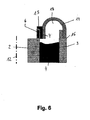
- Fig. 6 shows a bushing with an outer sleeve 3, an inner sleeve 2 and an elastic medium 4.
- the bushing has a membrane 14 which is hinged to the outer sleeve 3 rotatably.
- the membrane 94 is positioned in a recess 16 of the outer sleeve 3.
- the inner sleeve 2 is associated with a sensor electrode 6.
- the rotatable free end of the membrane 14 is associated with a sliding sleeve 15, which has a sensor electrode 7.
- the sliding sleeve 15 is L-shaped and is positively applied to the upper edge of the inner sleeve 2.
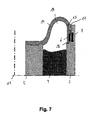
- Fig. 7 shows a bushing with an inner sleeve 2, an outer sleeve 3 and a diaphragm 14 which is rotatably connected at its one end to the inner sleeve 2.
- the free end of the membrane 14 is connected to a sliding sleeve 15, which has a sensor electrode 6.
- the sensor electrode 6 is located opposite a sensor electrode 7 which is assigned to the outer sleeve 3.
- the sliding sleeve 15 is received in a recess 16 of the outer sleeve 3.
- the sliding sleeve 15 has a seal 17, which seals the volume 18 together with the membrane 14 and the elastic medium 4.
- the seal 17 slides on the inner wall of the outer sleeve 3.
- the seal 17 is arranged above the sensor electrode 6 in the region of the upper end of the outer sleeve 3.
- Fig. 8 shows a bushing with an outer sleeve 3 and an inner sleeve 2, which are interconnected by an elastic medium 4.
- the bushing further has a membrane 14, which is articulated at one end against rotation on the inner sleeve 2.
- the free end of the membrane 14 is connected to a sliding sleeve 15, which is associated with a sensor electrode 6.
- a seal 17 is arranged, which slidably rests against the outer wall of the outer sleeve 3.
- the sliding sleeve 15 is positioned in a recess 16 of the outer sleeve 3.
- the outer sleeve 3 is a sensor electrode 7, the sliding sleeve 15 associated with a sensor electrode 6.
- the membrane 14, the elastic medium 4 and the seal 17 define, together with the inner sleeve 2 and the outer sleeve 3, a volume 18 analogous to FIG. 7.
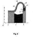
- Fig. 9 shows a bushing with an inner sleeve 2 and an outer sleeve 3, which are interconnected by an elastic medium 4.
- a diaphragm 14 is articulated rotatably.
- the free end of the membrane 14 is connected to a sliding sleeve 15, which is associated with a sensor electrode 6.
- a seal 17 is arranged, which is designed as a sealing lip.
- the sealing lip rests on the upper edge of the outer sleeve 3 and is in sliding connection with this.
- the sliding sleeve 15 is positioned in a recess 16 of the outer sleeve 3, which, analogous to the embodiment according to FIG. 7, faces the volume 18.
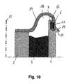
- Fig. 10 shows a bushing with an inner sleeve 2 and an outer sleeve 3, which are interconnected by an elastic medium 4.
- a diaphragm 14 is articulated rotatably with its one end.
- the other end of the membrane 14 is associated with a sliding sleeve 15, which is associated with a sensor electrode 6.
- a sealing lip seal 17 is arranged at the free end of the diaphragm 14 facing away from the end of the sliding sleeve 15 .
- the sealing lip 17 comes on a projection 18 of the lateral surface of the outer sleeve 3 to the plant.
- the sliding sleeve 15 is arranged in a recess 16 of the outer sleeve 3, which is analogous to Figures 5, 6 and 8 to the outside - so the volume 18 facing away - is formed.
- the outer sleeve 3 is associated with a sensor electrode 7.
- FIG. 11 shows a bushing with an inner sleeve 2, an outer sleeve 3 and a diaphragm 14 which, with one end, is non-rotatably attached to the inner sleeve 2 is articulated.
- the free end of the membrane 14 is connected to a sliding sleeve 15, which has a sensor electrode 6.
- the sensor electrode 6 is located opposite a sensor electrode 7 which is assigned to the outer sleeve 3.
- the sliding sleeve 15 is received in a recess 16 of the outer sleeve 3.
- the sliding sleeve 15 has a seal 19, which seals the volume 18 together with the membrane 14 and the elastic medium 4.
- the seal 19 comprises a sealing lip 19d which slidably bears against the outer wall of the outer sleeve 3.
- the seal 19 further comprises two sealing lips 19 a and 19 b, which slide on the outer wall of the outer sleeve 3.
- the seal 19 surrounds the edge of the outer sleeve 3 and stabilizes the guidance of the sliding sleeve 15.
- the seal 19 is to the stiffening a Stabilization ring 20 embedded.
Landscapes
- Engineering & Computer Science (AREA)
- Mechanical Engineering (AREA)
- Automation & Control Theory (AREA)
- General Engineering & Computer Science (AREA)
- Power Engineering (AREA)
- Physics & Mathematics (AREA)
- General Physics & Mathematics (AREA)
- Measurement Of Length, Angles, Or The Like Using Electric Or Magnetic Means (AREA)
- Measurement Of Mechanical Vibrations Or Ultrasonic Waves (AREA)
- Measuring Pulse, Heart Rate, Blood Pressure Or Blood Flow (AREA)
- Transmission And Conversion Of Sensor Element Output (AREA)
Abstract
Description
- Die Erfindung betrifft eine Buchse, umfassend eine Sensoreinrichtung, eine Innenhülse und eine diese umgebende Außenhülse, wobei zwischen Innenhülse und Außenhülse eine elastisches Medium angeordnet ist, welches einer Bewegung der Innenhülse relativ zur Außenhülse entgegen wirkt und wobei die Sensoreinrichtung die Bewegung detektiert.
- Derartige Buchsen sind aus dem Stand der Technik bereits bekannt. Sie finden Verwendung in Fahrwerken von Kraftfahrzeugen. Die Verwendung dieser Buchsen ermöglicht beispielsweise eine Nachführung bzw. Einstellung von Scheinwerferpositionen. Insbesondere können die Scheinwerfer eines beladenen Fahrzeuges derart nachgeregelt werden, dass ihre Abstrahlcharakteristik der eines unbeladenen Fahrzeugs entspricht.
- Eine solche Buchse kann auch zur Niveauregulierung von luftgefederten Fahrzeugen dienen, bzw. Signale für eine adaptive Fahrwerksregelung liefern.
- Hierzu werden die gattungsbildenden Buchsen im Fahrwerk von Kraftfahrzeugen positioniert. Dabei ist eine Hülse der Buchse dem Chassis und eine andere Hülse der Buchse einem Rad oder einem Achsenteil zugeordnet. Je nach Einfederweg bzw. Belastung des Kraftfahrzeuges stellt sich zwischen dem Achsenteil und dem Chassis ein Winkel ein, der einem Verdrehwinkel der Innenhülse relativ zur Außenhülse der Buchse entspricht.
- Dieser Verdrehwinkel kann erfasst werden und durch eine nachgelagerte Elektronikeinrichtung verarbeitet werden. Die Elektronikeinrichtung kann dann an die Scheinwerfer des Kraftfahrzeugs Signale senden, die eine Nachregelung der Scheinwerferpositionen bewirken.
- Die Signale können auch Ventile einer Niveauregelung öffnen. Im Falle einer Fahrwerksregelung werden Stellströme an ein Dämpferventil geschaltet.
- Im Betrieb eines Kraftfahrzeugs werden die Hülsen einer Buchse jedoch nicht nur relativ zueinander verdreht, sondern des Weiteren sowohl translatorisch als auch kardanisch gegeneinander verschoben. Hierbei ist problematisch, dass der Verdrehwinkel, der sich lediglich aus einer rotatorischen oder torsionalen Bewegung der Hülsen gegeneinander ergibt, nur sehr ungenau gemessen werden kann. Die Folge hiervon ist eine Fehleinstellung der Scheinwerfer des Kraftfahrzeuges.
- Der Erfindung liegt daher die Aufgabe zu Grunde, eine Buchse der eingangs genannten Art derart auszugestalten und weiterzubilden, dass eine möglichst exakte Erfassung des Verdrehwinkels der Innenhülse relativ zur Außenhülse gewährleistet ist.
- Die vorliegende Erfindung löst die zuvor genannte Aufgabe durch die Merkmale des Patentanspruchs 1. Danach ist eine Buchse der eingangs genannten Art dadurch gekennzeichnet, dass die Sensoreinrichtung Mittel aufweist, welche Bewegungen der Innenhülse relativ zur Außenhülse zumindest teilweise kompensieren, welche einer torsionalen Bewegung der lnnenhülse relativ zur Außenhülse überlagert sind.
- Erfindungsgemäß ist erkannt worden, dass kardanische und/oder translatorische Bewegungen der Innenhülse relativ zur Außenhülse das Messergebnis einer Sensoreinrichtung verfälschen. In einem weiteren Schritt ist erkannt worden, dass die einzelnen Bewegungen der Außenhülse bzw. lnnenhülse einer Buchse messtechnisch voneinander entkoppelt werden müssen. Schließlich ist erkannt worden, dass die Vorkehrung von Mitteln, welche solche Bewegungen kompensieren, die nicht zu einer rotatorischen bzw. torsionaleri Bewegung der Außenhülse relativ zur Innenhülse beitragen, die Messgenauigkeit einer Buchse erheblich erhöhen. lnsoweit ist eine Buchse angegeben, welche den Verdrehwinkel zwischen Innenhülse und Außenhülse möglichst exakt erfassen kann. Folglich ist die eingangs genannte Aufgabe gelöst.
- Die Mittel könnten ersten und zweiten Sensorelektroden zugeordnet sein, wobei eine Sensorelektrode der Innenhülse und eine Sensorelektrode der Außenhülse zugeordnet ist. Die Vorkehrung von Sensorelektroden erlaubt eine problemlose Anordnung der Mittel an den jeweiligen Hülsen. Durch die konkrete Zuordnung der Sensorelektroden an einzelne Hülsen kann die Verdrehung der Hülsen relativ zueinander besonders genau erfasst werden.
- Die Mittel könnten einander gegenüber liegende erste und zweite Kondensatorplatten umfassen. Die Verwendung von Kondensatorplatten erlaubt die exakte Bestimmung der Kapazität eines Kondensators. Die Kapazität eines Plattenkondensators ist proportional zur Fläche des Kondensators. Die Fläche eines Kondensators ist ein Maß für die Überlappung zweier sich gegenüber liegender Kondensatorplatten. Aus dem Maß der Überlappung kann auf die relative Verdrehung der Kondensatorplatten und damit der Hülsen der Buchse geschlossen werden.
- Vor diesem Hintergrund ist auch denkbar, dass Kondensatorplatten innerhalb des elastischen Mediums, beispielsweise innerhalb eines Elastomers, angeordnet sind. Diese konkrete Ausgestaltung gewährleistet eine besonders kompakte Ausführungsform der Buchse. die Kondensatorplatten werden durch das Elastomer geschützt und das Elastomer fungiert als Dielektrikum. Hierdurch wird die Kapazität des Kondensators erhöht, wodurch dessen Kapazität leichter zu messen ist.
- Die Mittel könnten einander gegenüber liegende erste und zweite Leiterstrukturen umfassen, welche mäanderförmig ausgestaltet und induktiv wirksam sind. Die Vorkehrung mäanderförmig ausgestalteter Leiterstrukturen erlaubt die wirksame und effektive Erzeugung von Induktionsspannungen in Abhängigkeit von der Überlappung der einander gegenüber liegenden Leiterstrukturen. Durch diese konkrete Ausgestaltung ist eine induktive Messung des Verdrehwinkels möglich.
- Die Mittel auf einer Sensorelektrode könnten eine andere flächige Ausdehnung als die Mittel auf der anderen Sensorelektrode aufweisen. Dabei ist ganz konkret denkbar, dass die Mittel auf der zweiten Sensorelektrode als Quadrate und die Mittel auf der erste Sensorelektrode als Rechtecke ausgestaltet sind. Dabei könnten die Rechtecke auf der ersten Sensorelektrode unterschiedliche Flächen aufweisen. Diese konkrete Ausgestaltung ist von Vorteil, wenn sich die Mittel der ersten Sensorelektrode und der zweiten Sensorelektrode so gegenüber liegen, dass bei einer Radialverschiebung der Außenhülse relativ zur Innenhülse der Überlappungsgrad bestimmter einander gegenüber liegender Mittel geändert wird und der Überlappungsgrad anderer sich gegenüber liegender Mittel konstant bleibt. Durch diese konkrete Ausgestaltung ist zusätzlich zu einer torsionalen Bewegung eine radiale Bewegung elektrisch erfassbar. Unter flächenmäßiger Ausdehnung wird hierbei die maximale Ausdehnung der Kondensatorplatten bzw. der mäanderförmigen Leiterstrukturen verstanden. Die hier beschriebene Wirkungsweise ist sowohl auf Kondensatorplatten als auch auf induktiv wirkende Leiterstrukturen anwendbar.
- Die Mittel könnten relativ zur Buchsenachse umfänglich angeordnet sein. Diese konkrete Ausgestaltung stellt sicher, dass ein elektrisches Signal nicht nur von zwei einander gegenüber liegenden Kondensatorplatten oder Leiterstrukturen erzeugt wird, sondern dass eine Vielzahl von elektrischen Signalen von einer Vielzahl einander gegenüber liegender Leiterstrukturen bzw. Kondensatorplatten erzeugbar sind. Hierdurch wird die Auflösung der Verdrehwinkelmessung erhöht. Es ist denkbar, dass die Kondensatorplatten oder Leiterstrukturen kreisförmig, insbesondere konzentrisch zur Buchsenachse, auf einer Sensorelektrode angeordnet sind.
- Zumindest einer Sensorelektrode könnte eine Tellerfeder zugeordnet sein oder könnte als Tellerfeder ausgebildet sein. Die Verwendung einer Tellerfeder erlaubt das Zusammenführen zweier Sensorelektroden unter Vorspannung. Bei einer kardanischen Verkippung der Außenhülse relativ zur Innenhülse kompensiert die Vorspannung der Tellerfeder die Bewegungen der kardanischen Bewegung, die einer torsionalen Bewegung überlagert sind. Bei dieser konkreten Ausgestaltung ist es möglich, dass der Abstand zweier Kondensatorplatten bzw. einander gegenüber liegender Leiterstrukturen auch bei kardanischer Bewegung nahezu konstant bleibt.
- Vor diesem Hintergrund ist denkbar, Tellerfedern aus Stahl oder Kunststoff zu verwenden, die eine Materialstärke von 0,1 bis 0,2 mm aufweisen. Diese Materialstärke hat sich als besonders vorteilhaft erwiesen, um eine ausreichende Vorspannung zu realisieren.
- Den Sensorelektroden und/oder den Mittel könnten folienartige Lagen zugeordnet sein. Folienartige Lagen schützen einerseits sowohl die Sensorelektroden als auch die Mittel. Dabei ist denkbar, dass eine Sensorelektrode sowohl auf ihrer den Mitteln abgewandten Seite als auch auf der den Mitteln zugewandten Seite mit einer Folie versehen ist. Die Mittel selbst könnten ihrerseits wieder von einer Folie bedeckt sein. Diese konkrete Ausgestaltung stellt sicher, dass sowohl die Sensorelektrode als auch die Mittel in einer dreilagigen Folienanordnung eingebettet sind. Hierdurch werden die Folien und die Sensorelektroden vor Umwelteinflüssen geschützt. Vor diesem Hintergrund ist auch denkbar, in den Folien Dieelektrika einzubinden, welche die Kapazität einer Kondensatoranordnung erhöhen. Ganz konkret ist vor diesem Hintergrund denkbar, die Folien als Polyesterfolien auszugestalten. Polyester hat sich als besonders gebrauchstaugliches Material für die Anwendung in Fahrwerksbuchsen erwiesen.
- Schließlich ist auch denkbar, dass eine Folie mit Kondensatorplatten oder Leiterstrukturen als Sensorelektrode fungiert. Die Kondensatorplatten oder Leiterstruktruren könnten auf die Folie auflaminiert oder aufgeätzt sein. Sensorelektroden dieser Ausgestaltung zeigen eine besondere Elastizität, so dass der Abstand einander gegenüberliegender Kondensatorplatten und Leiterstrukturen auch bei radialen, axialen oder kardanischen Bewegungen bzw. Verkippungen der Hülsen nahezu konstant bleibt. Ein Verbund aus zwei solchen Sensorelektroden könnte zusätzlich zwischen zwei Tellerfedern aufgenommen werden, welche die nahezu konstante Beabstandung zweier Folien zusätzlich sicherstellen.
- Die Mittel könnten zumindest ein bereichsweise flexibel deformierbares Element umfassen, welches mit einem Ende drehfest entweder an der Innenhülse oder an Außenhülse angelenkt und mit seinem anderen Ende rotationsbeweglich der Außenhülse bzw. der Innenhülse zugeordnet ist. Diese konkrete Ausgestaltung realisiert auf überraschend einfache Weise die Kompensierung von Bewegungen, die einer Rotationsbewegung von Außenhülse und Innenhülse überlagert sind. Durch die bereichsweise flexible Deformierbarkeit des Elements werden axiale, radiale, kardanische oder andere translatorische Bewegungen der Außenhülse bzw. der Innenhülse relativ zueinander von dem Element selbst aufgenommen und gehen in diesem quasi verloren. Lediglich rotatorische Bewegungen werden auf das freie Ende übertragen. Insoweit ist durch diese konkrete Ausgestaltung eine mechanische Kompensierung von Bewegungen realisiert, die einer torsionalen bzw. rotatorischen Bewegung der Innenhülse relativ zur Außenhülse überlagert sind.
- Vor diesem Hintergrund ist denkbar, dass das rotationsbewegliche Ende an einer Gleithülse angelenkt ist, die relativ zur Außenhülse bzw. Innenhülse verdrehbar ist. Die Vorkehrung einer Gleithülse erlaubt vorteilhaft die Positionierung von Mitteln wie Kondensatorplatten oder induktiv wirkenden Leiterstrukturen am freien Ende des elastisch deformierbaren Elements. Die Gleithülse kann aus einem Kunststoff oder Metall gefertigt sein und bietet den Mitteln eine stabile Auflage. Insoweit fungiert die Gleithülse als Aufnahme für eine Sensorelektrode oder kann sogar als solche ausgestaltet sein.
- Die Innenhülse und/oder die Außenhülse könnten Ausnehmungen zur Aufnahme zur Gleithülse oder des Elements aufweisen. Durch diese konkrete Ausgestaltung ist sicher gestellt, dass an der Außenhülse bzw. der Innenhülse keine Überstände auftreten, an denen weitere Bauteile eines Fahrwerks hängen bleiben können. Insoweit stellt eine so ausgestaltete Fahrwerksbuchse eine besonders glatte und gebrauchstaugliche Oberfläche zur Verfügung.
- Denkbar ist auch, dass die Gleithülse mit Rastmitteln an der Innenhülse oder der Außenhülse geführt wird. Als Rastmittel könnten Nut und Federelemente vorgesehen sein. Dabei kann die Nut entweder in der Gleithülse oder in der Innenhülse bzw. Außenhülse ausgebildet sein. Hierdurch ist eine nahezu spielfreie Führung der Gleithülse möglich.
- Ganz in Abhängigkeit von dem Einsatz der Buchse kann die Gleithülse der Außenhülse oder der Innenhülse zugeordnet sein. Die Zuordnung der Gleithülse zur Innenhülse bewirkt geringere Bewegungen der Gleithülse, da diese einen geringeren Bogenwinkel beschreiben muss, wenn sie bewegt wird.
- Diese konkrete Ausgestaltung erlaubt eine Minimierung des Verschleißes der Gleithülse, da diese geringeren Reibungsverlusten unterworfen wird.
- Der Gleithülse könnte eine Dichtung zugeordnet sein. Die Vorkehrung einer Dichtung verhindert wirksam das Eindringen von Verschmutzungen oder Schmutzpartikeln in den Bereich der einander gegenüber liegenden Mittel. Insbesondere wird hierdurch wirksam vermieden, dass Schmutzpartikel zwischen Kondensatorplatten eindringen und die Kapazität eines Kondensators verändern und damit Messwerte verfälschen.
- Vor diesem Hintergrund ist denkbar, dass die Dichtung als Dichtlippe ausgebildet ist. die Dichtlippe könnte dabei schleifend auf einem Vorsprung der Außenhülse bzw. der Innenhülse gleiten. Durch diese Ausgestaltung ist eine besonders zuverlässige Abdichtung der Sensoreinrichtung sichergestellt.
- Die Dichtung könnte mehrere Dichtlippen aufweisen. Mit diesen könnte die Dichtung einen Rand der Außen- oder Innenhülse umgreifen und die Führung der Gleithülse stabilisieren sowie die Dichtwirkung erhöhen.
- Es ist des Weiteren denkbar, dass in der Gleithülse eine Ausnehmung vorgesehen ist, in der eine Dichtung positioniert ist. Die Dichtung kann gleitend an der Wandung der Außenhülse bzw. der Innenhülse verfahren werden.
- Das elastisch deformierbare Element könnte als Membran ausgestaltet sein. Diese konkrete Ausgestaltung stellt sicher, dass die Buchse zumindest einseitig durch die Membran abdichtbar ist. Hierdurch kann die Sensoreinrichtung wirksam vor Verschmutzungen geschützt werden. Die Membran kann beispielsweise aus einem Elastomer, Gummi, Polyurethan, Silikon oder einem thermoplastischen Elastomer bestehen. Diese Werkstoffe zeichnen sich in besonderer Weise durch hohe Elastizität und chemische Resistenz aus. Eine chemische Resistenz ist insbesondere beim Einsatz in Kraftfahrzeugen von Vorteil, da Buchsen häufig Maschinen- und Motorölen ausgesetzt werden. Diese Öle können chemisch agressiv sein.
- Die Membran könnte in radialer und axialer Richtung weich und in torsionaler Richtung steif wirkend ausgebildet sein. Dies könnte durch eine Gewebeverstärkung der Membran oder eine andere verstärkende Einlage innerhalb der Membran erzielt werden. Insbesondere sind thermoplastische Fäden denkbar, aus denen die Gewebeverstärkung oder die Einlage gefertigt sein könnte. Hierdurch ist eine besonders hohe Torsionssteifigkeit einer Membran einstellbar.
- Die Membran könnte in axialer Richtung eine Vorspannung aufweisen. Dies erlaubt eine genaue Positionierung der Gleithülse und verhindert deren Abheben oder Loslösen von der Innenhülse bzw. Außenhülse.
- Die Dichtung und das Element könnten ein Volumen abdichten, in dem die Mittel der Sensoreinrichtung positioniert sind. Diese konkrete Ausgestaltung stellt auf besonders raffinierte Weise sicher, dass die Sensoreinrichtung eine lange Lebensdauer und hohe Messgenauigkeit aufweist, da diese vor Verschmutzungen geschützt wird.
- Das elastische Medium, welches die Außenhülse von der Innenhülse abtrennt, könnte als Elastomer, Polyurethan, Silikon oder thermoplastisches Elastomer ausgestaltet sein. Diese Werkstoffe zeichnen sich durch eine hohe Elastizität aus. Des Weiteren ist denkbar, dass das elastische Medium als Gummi ausgestaltet ist. Gummi lässt sich in besonders günstiger Weise mit metallischen Hülsen durch Vulkanisation fest verbinden.
- Es gibt nun verschiedene Möglichkeiten, die Lehre der vorliegenden Erfindung in vorteilhafter Weise auszugestalten und weiterzubilden. Dazu ist einerseits auf die dem Patentanspruch 1 nachgeordneten Ansprüche, andererseits auf die nachfolgende Erläuterung bevorzugter Ausführungsbeispiele der Erfindung an Hand der Zeichnung zu verweisen.
- In Verbindung mit der Erläuterung der bevorzugten Ausführungsbeispiele der Erfindung an Hand der Zeichnung werden auch im allgemeinen bevorzugte Ausgestaltungen und Weiterbildungen der Lehre erläutert.
- In der Zeichnung zeigen
- Fig. 1
- eine Buchse mit zwei Sensorelektroden,
- Fig. 2
- eine Schnittansicht von Sensorelektroden, denen flächige Lagen zugeordnet sind,
- Fig. 3
- zwei Sensorelektroden mit Kondensatorplatten,
- Fig. 4
- zwei Sensorelektroden mit induktiv wirksamen Leiterstrukturen,
- Fig. 5
- eine Buchse mit einer Gleithülse, die der Außenhülse zugeordnet ist,
- Fig. 6
- eine Buchse mit einer Gleithülse, die der Innenhülse zugeordnet ist,
- Fig. 7
- eine Buchse mit einer Gleithülse, welche eine Dichtung aufweist, die dem drehbeweglichen Ende eines bereichsweise flexibel deformierbaren Elements zugewandt ist,
- Fig. 8
- eine Buchse mit einer Gleithülse, welche eine Dichtung aufweist, die dem drehbeweglichen Ende eines bereichsweise flexibel deformierbaren Elements abgewandt ist,
- Fig. 9
- eine Buchse mit einer Gleithülse, der eine Dichtlippe zugeordnet ist,
- Fig. 10
- eine Buchse mit einer Gleithülse, die eine Dichtlippe aufweist, welche auf einem Vorsprung der Außenhülse gleitet, und
- Fig. 11
- eine Buchse mit einer Gleithülse, die eine Dichtung mit mehreren Dichtlippen aufweist.
- Fig. 1 zeigt eine Buchse mit einer Sensoreinrichtung 1, einer Innenhülse 2 und einer diese umgebenden Außenhülse 3. Zwischen Innenhülse 2 und Außenhülse 3 ist ein elastisches Medium 4 angeordnet, welches als Gummi ausgestaltet ist. Das elastische Medium 4 wirkt einer Bewegung der Innenhülse 2 relativ zur Außenhülse 3 entgegen. Das elastische Medium 4 führt die Innenhülse 2 relativ zur Außenhülse 3 und ermöglicht eine gezielte Verdrehung der Innenhülse 2 relativ zur Außenhülse 3. Die Sensoreinrichtung 1 detektiert die Bewegung der Innenhülse 2 relativ zur Außenhülse 3.
- Die Sensoreinrichtung 1 weist Mittel auf, die Bewegungen der Innenhülse 2 relativ zur Außenhülse 3 kompensieren, welche einer torsionalen Bewegung der Innenhülse 2 relativ zur Außenhülse 3 überlagert sind.
- Die Buchse gemäß Fig. 1 weist eine erste Sensorelektrode 6 auf, welche der Innenhülse 2 zugeordnet ist. Die Buchse weist des Weiteren eine Sensorelektrode 7 auf, weiche der Außenhülse 3 zugeordnet ist. Die Innenhülse 2 und die Außenhülse 3 sind konzentrisch zur Buchsenachse 12 angeordnet.
- Fig. 2 zeigt in schematischer Ansicht die Sensorelektroden 6 und 7. Diese umfassen erste Kondensatorplatten 8 und zweite Kondensatorplatten 9. Den Sensorelektroden 6 und 7 und den Kondensatorplatten 8 und 9 sind folienartige Lagen 13 aus Polyester zugeordnet. Die Sensorelektroden 6 und 7 sind in den Polyesterfolien 13 eingebettet. Die Kondensatorplatten 8 und 9 sind ebenfalls zwischen zwei Polyesterfolien 13 eingebettet.
- Fig. 3 zeigt in ihrem oberen Teil eine Draufsicht auf die Sensorelektrode 7 gemäß Fig. 2. Diese weist Kondensatorplatten 9a und 9b auf. der untere Teil der Fig. 3 zeigt die Sensorelektrode 6. Diese weist Kondensatorplatten 8a und 8b auf. Die Kondensatorplatten 9a und 9b weisen eine andere Ausdehnung als die Kondensatorplatten 8a und 8b auf. Die Kondensatorplatten 8a und 8b sind rechteckig ausgebildet. Auf der Sensorelektrode 6 sind acht rechteckige Kondensatorplatten umfänglich um die Rotationsachse 12 angeordnet. auf der Sensorelektrode 7 sind um die Buchsenachse 12 umfänglich vier nahezu quadratische Kondensatorplatten 9a und 9b angeordnet.
- Wenn die Kondensatorplatten 9a, 9b und 8a, 8b einander gegenüber liegen, verändert sich bei einem radialen oder rotatorischen Versatz der Außenhülse 3 zur Innenhülse 2 der Überlappungsgrad der sich gegenüber liegenden Kondensatorplatten 8a, 8b und 9a, 9b.
- Wenn sich nun die Kondensatorplatten 9a und 8a gegenüber liegen, kann eine radiale bzw. translatorische Verschiebung, nämlich in Pfeilrichtung, durch die Veränderung des Überlappungsgrades der Kondensatorplatten 8a und 9a ermittelt werden. Der Überlappungsgrad der Kondensatorplatten 8b und 9b wird bei einer solchen Radialverschiebung nahezu nicht verändert, da sich die Fläche der Kondensatorplatte 9b innerhalb des Bereiches der Kondensatorplatten 8b verschiebt, insoweit ist eine radiale Bewegung unabhängig von einer torsionalen Bewegung detektierbar.
- Fig. 4 zeigt Leiterstrukturen 10a, 10b und 11a, 11b, die mäanderförmig ausgestaltet sind. Die Leiterstrukturen 10a, 10b und 11a, 11 b sind Sensorelektroden 6 und 7 zugeordnet und induktiv wirksam. Die mäanderförmig ausgestalteten Leiterstrukturen 10a, 10b und 11a, 11 b bedecken näherungsweise Rechteckflächen. Die flächige Ausgestaltung der induktiv wirksamen Leiterstrukturen 10a, 10b und 11 a, 11 b wird so gewählt, dass das im Rahmen von Fig. 3 beschriebene Messprinzip zur Erfassung radialer und torsionaler Verschiebung durchführbar ist.
- Die Kondensatorplatten 8a, 8b und 9a, 9b sowie die Leiterstrukturen 10a, 10b und 11 a, 11 b können auf Polyesterfolien auflaminiert oder aufgeäzt sein. Für Laminier- oder Ätzverfahren eignen sich in besonderer Weise Kunststoffträger, insbesondere Polyesterfolien.
- Durch die Verwendung von Kunststoffträgern oder folienartigen Lagen wird den Sensorelektroden eine besondere Elastizität verliehen. Hierdurch ist sicher gestellt, dass der Abstand zwischen Kondensatorplatten und induktiv wirkenden Leiterstrukturen auch bei kardanischer Bewegung der Innenhülse 2 und der Außenhülse 3 relativ zueinander konstant gehalten werden kann. Die Sensorelektrode führt als Ganzes auf Grund ihrer Elastizität Kippbewegungen aus, die mit einer kardanischen Bewegung einhergehen. Insoweit führen die einander gegenüber liegenden Kondensatorplatten oder Leiterstrukturen nur dann größere relative Bewegungen zueinander aus, wenn die Außenhülse 3 bzw. die Innenhülse 2 relativ zueinander verdreht werden.
- Fig. 5 zeigt eine Innenhülse 2, eine Außenhülse 3 und ein elastisches Medium 4, das als Gummi ausgestaltet ist. Der Buchse gemäß Fig. 5 ist ein zumindest bereichsweise flexibel deformierbares Element 14 zugeordnet, welches mit einem Ende drehfest an der in Innenhülse 2 angelenkt ist. Mit seinem anderen Ende ist es rotationsbeweglich der Außenhülse 3 zugeordnet.
- Das rotationsbewegliche Ende ist an einer Gleithülse 15 angelenkt, die relativ zur Außenhülse 3 verdrehbar ist. Die Außenhülse 3 weist eine Ausnehmung 16 auf, in welcher die Gleithülse 15 aufgenommen ist. Die Mantelflächen der Gleithülse 15 und der Außenhülse 3 fluchten miteinander, da die Gleithülse 15 in der Ausnehmung 16 aufgenommen ist. Das zumindest bereichsweise flexibel deformierbare Element 14 ist als Membran aus einem elastomeren Werkstoff ausgebildet. Das Element 14 begrenzt mit dem elastischen Medium 4 ein Volumen 18. Der Außenhülse 3 ist eine Sensorelektrode 7, der Innenhülse 2 über die Gleithülse 15 mittelbar eine Sensorelektrode 6 zugeordnet.
- Fig. 6 zeigt eine Buchse mit einer Außenhülse 3, einer Innenhülse 2 und einem elastischen Medium 4. Die Buchse weist eine Membran 14 auf, die an der Außenhülse 3 drehfest angelenkt ist. Die Membran 94 ist in einer Ausnehmung 16 der Außenhülse 3 positioniert. Der Innenhülse 2 ist eine Sensorelektrode 6 zugeordnet. Dem drehbeweglichen freien Ende der Membran 14 ist eine Gleithülse 15 zugeordnet, welche eine Sensorelektrode 7 aufweist. Die Gleithülse 15 ist L-förmig ausgestaltet und ist formschlüssig an die Oberkante der Innenhülse 2 angelegt.
- Fig. 7 zeigt eine Buchse mit einer Innenhülse 2, einer Außenhülse 3 und einer Membran 14, welche mit ihrem einen Ende drehfest an der Innenhülse 2 angelenkt ist. Das freie Ende der Membran 14 ist mit einer Gleithülse 15 verbunden, die eine Sensorelektrode 6 aufweist. Die Sensorelektrode 6 liegt einer Sensorelektrode 7 gegenüber, die der Außenhülse 3 zugeordnet ist. Die Gleithülse 15 wird in einer Ausnehmung 16 der Außenhülse 3 aufgenommen. Die Gleithülse 15 weist eine Dichtung 17 auf, welche das Volumen 18 zusammen mit der Membran 14 und dem elastischen Medium 4 abdichtet. Die Dichtung 17 läuft gleitend an der Innenwandung der Außenhülse 3. Die Dichtung 17 ist oberhalb der Sensorelektrode 6 im Bereich des oberen Endes der Außenhülse 3 angeordnet.
- Fig. 8 zeigt eine Buchse mit einer Außenhülse 3 und einer Innenhülse 2, welche durch ein elastisches Medium 4 miteinander verbunden sind. Die Buchse weist des Weiteren eine Membran 14 auf, welche mit ihrem einen Ende drehfest an der Innenhülse 2 angelenkt ist. Das freie Ende der Membran 14 ist mit einer Gleithülse 15 verbunden, welcher eine Sensorelektrode 6 zugeordnet ist. An dem dem freien Ende der Membran 14 abgewandten Teil der Gleithülse 15 ist eine Dichtung 17 angeordnet, welche gleitend an der Außenwandung der Außenhülse 3 anliegt. Die Gleithülse 15 ist in einer Ausnehmung 16 der Außenhülse 3 positioniert. Der Außenhülse 3 ist eine Sensorelektrode 7, der Gleithülse 15 eine Sensorelektrode 6 zugeordnet. Die Membran 14, das elastische Medium 4 sowie die Dichtung 17 begrenzen zusammen mit der Innenhülse 2 und der Außenhülse 3 ein Volumen 18 analog zur Figur 7.
- Fig. 9 zeigt eine Buchse mit einer Innenhülse 2 und einer Außenhülse 3, welche durch ein elastisches Medium 4 miteinander verbunden sind. An der Innenhülse 2 ist eine Membran 14 drehfest angelenkt. Das freie Ende der Membran 14 ist mit einer Gleithülse 15 verbunden, welcher eine Sensorelektrode 6 zugeordnet ist. An dem dem freien Ende der Membran zugewandten Ende der Gleithülse 15 ist eine Dichtung 17 angeordnet, die als Dichtlippe ausgestaltet ist. Die Dichtlippe liegt auf der Oberkante der Außenhülse 3 auf und steht mit dieser gleitend in Verbindung. Die Gleithülse 15 ist in einer Ausnehmung 16 der Außenhülse 3 positioniert, welche analog der Ausgestaltung gemäß Fig. 7 dem Volumen 18 zugewandt ist.
- Fig. 10 zeigt eine Buchse mit einer Innenhülse 2 und einer Außenhülse 3, die durch ein elastisches Medium 4 miteinander verbunden sind. An der Innenhülse 2 ist eine Membran 14 mit ihrem einen Ende drehfest angelenkt. Dem anderen Ende der Membran 14 ist eine Gleithülse 15 zugeordnet, welcher eine Sensorelektrode 6 zugeordnet ist. An dem dem freien Ende der Membran 14 abgewandten Ende der Gleithülse 15 ist eine als Dichtlippe ausgebildete Dichtung 17 angeordnet. Die Dichtlippe 17 kommt auf einer Auskragung 18 der Mantelfläche der Außenhülse 3 zur Anlage. Die Gleithülse 15 ist in einer Ausnehmung 16 der Außenhülse 3 angeordnet, welche analog den Figuren 5, 6 und 8 nach außen - also dem Volumen 18 abgewandt - ausgebildet ist. Der Außenhülse 3 ist eine Sensorelektrode 7 zugeordnet.
- Fig. 11 zeigt eine Buchse mit einer Innenhülse 2, einer Außenhülse 3 und einer Membran 14, welche mit ihrem einen Ende drehfest an der Innenhülse 2 angelenkt ist. Das freie Ende der Membran 14 ist mit einer Gleithülse 15 verbunden, die eine Sensorelektrode 6 aufweist. Die Sensorelektrode 6 liegt einer Sensorelektrode 7 gegenüber, die der Außenhülse 3 zugeordnet ist. Die Gleithülse 15 wird in einer Ausnehmung 16 der Außenhülse 3 aufgenommen.
- Die Gleithülse 15 weist eine Dichtung 19 auf, welche das Volumen 18 zusammen mit der Membran 14 und dem elastischen Medium 4 abdichtet. Die Dichtung 19 umfasst eine Dichtlippe 19d, welche an der Außenwandung der Außenhülse 3 gleitend anliegt. Die Dichtung 19 weist des Weiteren zwei Dichtlippen 19a und 19b auf, die an der Außenwandung der Außenhülse 3 gleiten. Eine Dichtlippe 19 c gleitet an der Innenwandung der Außenhülse 3. Durch die Ausbildung der Dichtlippen 19a, 19b, 19c und 19d umgreift die Dichtung 19 den Rand der Außenhülse 3 und stabilisiert die Führung der Gleithülse 15. In die Dichtung 19 ist zu deren Versteifung ein Stabilisierungsring 20 eingebettet.
- Hinsichtlich weiterer vorteilhafter Ausgestaltungen und Weiterbildungen der erfindungsgemäßen Lehre wird einerseits auf den allgemeinen Teil der Beschreibung und andererseits auf die beigefügten Patentansprüche verwiesen.
- Abschließend sei ganz besonders hervorgehoben, dass die zuvor rein willkürlich gewählten Ausführungsbeispiele lediglich zur Erörterung der erfindungsgemäßen Lehre dienen, diese jedoch nicht auf diese Ausführungsbeispiele einschränken.
Claims (15)
- Buchse, umfassend eine Sensoreinrichtung (1), eine Innenhülse (2) und eine diese umgebende Außenhülse (3), wobei zwischen Innenhülse (2) und Außenhülse (3) ein elastisches Medium (4) angeordnet ist, welches einer Bewegung der Innenhülse (2) relativ zur Außenhülse (3) entgegenwirkt, und wobei die Sensoreinrichtung (1) die Bewegung detektiert, dadurch gekennzeichnet, dass die Sensoreinrichtung (1) Mittel (8, 8a, 8b, 9, 9a, 9b,10, 10a, 10b, 11,11 a, 11 b, 14) aufweist, welche Bewegungen der Innenhülse (2) relativ zur Außenhülse (3) zumindest teilweise kompensieren, welche einer torsionalen Bewegung der Innenhülse (2) relativ zur Außenhülse (3) überlagert sind.
- Buchse nach Anspruch 1, dadurch gekennzeichnet, dass die Mittel (8, 8a, 8b, 9, 9a, 9b, 10,10a. 10b, 11, 11a, 11 b, 14) ersten und/ oder zweiten Sensorelektroden (6, 7) zugeordnet sind, wobei eine Sensorelektrode (6) der Innenhülse (2) und eine Sensorelektrode (7) der Außenhülse (3) zugeordnet ist.
- Buchse nach Anspruch 1 oder 2, dadurch gekennzeichnet, dass die Mittel einander gegenüberliegende erste und zweite Kondensatorplatten (8, 8a, 8b, 9, 9a, 9b) umfassen.
- Buchse nach einem der Ansprüche 1 bis 3, dadurch gekennzeichnet, dass die Mittel einander gegenüberliegende erste und zweite Leiterstrukturen (10,10a, 10b, 11, 11a, 11b) umfassen, welche mäanderförmig ausgestaltet und induktiv wirksam sind.
- Buchse nach Anspruch 3 oder 4, dadurch gekennzeichnet, dass die Mittel (8, 8a, 8b, 10, 10a, 10b) auf der ersten Sensorelektrode (6) eine andere flächige Ausdehnung als die Mittel (9, 9a, 9b, 11, 11a, 11 b) auf der zweiten Sensorefektrode (7) aufweisen.
- Buchse nach einem der Ansprüche 1 bis 5, dadurch gekennzeichnet, dass die Mittel (8, 8a, 8b, 9, 9a, 9b, 10, 10a, 10b, 11, 11a, 11 b) relativ zur Buchsenachse (12) umfänglich angeordnet sind.
- Buchse nach einem der Ansprüche 2 bis 6, dadurch gekennzeichnet, dass zumindest einer Sensorelektrode (6, 7) eine Tellerfeder zugeordnet ist oder zumindest eine Sensorelektrode (6, 7) als Tellerfeder ausgebildet ist.
- Buchse nach einem der Ansprüche 2 bis 7, dadurch gekennzeichnet, dass den Sensorelektroden (6, 7) und/ oder den Mitteln (8, 8a, 8b, 9, 9a, 9b, 10, 10a, 10b, 11, 11 a, 11 b) folienartige Lagen (13) zugeordnet sind.
- Buchse nach einem der Ansprüche 1 bis 8, dadurch gekennzeichnet, dass die Mittel ein zumindest bereichsweise flexibel deformierbares Element (14) umfassen, welches mit einem Ende drehfest entweder an der Innenhülse (2) oder an der Außenhülse (3) angelenkt und mit seinem anderen Ende rotationsbeweglich der Außenhülse (3) bzw. der Innenhülse (2) zugeordnet ist.
- Buchse nach Anspruch 9, dadurch gekennzeichnet, dass das rotationsbewegliche Ende an einer Gleithülse (15) angelenkt ist, die relativ zur Außenhülse (3) bzw. Innenhülse (2) verdrehbar ist.
- Buchse nach Anspruch 10, dadurch gekennzeichnet, dass die Innenhülse (2) und/ oder die Außenhülse (3) Ausnehmungen (16) zur Aufnahme der Gleithülse (15) oder des Elements (14) aufweist.
- Buchse nach Anspruch 10 oder 11, dadurch gekennzeichnet, dass der Gleithülse (15) eine Dichtung (17, 19) zugeordnet ist.
- Buchse nach Anspruch 12, dadurch gekennzeichnet, dass die Dichtung (17, 19) als Dichtlippe ausgebildet ist oder Dichtlippen (19a, 19b, 19c, 19d) umfasst.
- Buchse nach einem der Ansprüche 9 bis 13, dadurch gekennzeichnet, dass das Element (14) als Membran ausgebildet ist.
- Buchse nach einem der Ansprüche 12 bis 14, dadurch gekennzeichnet, dass die Dichtung (17) und das Element (14) ein Volumen (18) abdichten, in dem die Mittel der Sensoreinrichtung (1) positioniert sind.
Applications Claiming Priority (1)
| Application Number | Priority Date | Filing Date | Title |
|---|---|---|---|
| DE102006028902A DE102006028902B4 (de) | 2006-06-21 | 2006-06-21 | Buchse mit Sensoreinrichtung |
Publications (2)
| Publication Number | Publication Date |
|---|---|
| EP1870267A1 true EP1870267A1 (de) | 2007-12-26 |
| EP1870267B1 EP1870267B1 (de) | 2010-05-19 |
Family
ID=38235252
Family Applications (1)
| Application Number | Title | Priority Date | Filing Date |
|---|---|---|---|
| EP07011558A Not-in-force EP1870267B1 (de) | 2006-06-21 | 2007-06-13 | Buchse mit Sensoreinrichtung |
Country Status (3)
| Country | Link |
|---|---|
| EP (1) | EP1870267B1 (de) |
| AT (1) | ATE468240T1 (de) |
| DE (2) | DE102006028902B4 (de) |
Cited By (1)
| Publication number | Priority date | Publication date | Assignee | Title |
|---|---|---|---|---|
| WO2011048109A1 (de) * | 2009-10-21 | 2011-04-28 | Leopold Kostal Gmbh & Co Kg | Drehsteller |
Citations (3)
| Publication number | Priority date | Publication date | Assignee | Title |
|---|---|---|---|---|
| DE10221873A1 (de) * | 2002-05-15 | 2003-11-27 | Zf Lemfoerder Metallwaren Ag | Gummilager mit Einfederungssensor |
| FR2858673A1 (fr) * | 2003-08-07 | 2005-02-11 | Soc Technologie Michelin Stm | Articulation elastique d'assemblage et son utilisation pour mesurer un deplacement ou un effort |
| EP1707839A1 (de) * | 2005-03-31 | 2006-10-04 | Delphi Technologies, Inc. | Schwingungsdämpfende Lagerbuchse mit integriertem Geschwindigkeits/Wegsensor |
Family Cites Families (2)
| Publication number | Priority date | Publication date | Assignee | Title |
|---|---|---|---|---|
| FR2645924B1 (fr) * | 1989-04-18 | 1994-09-02 | Roulements Soc Nouvelle | Palier preassemble a elements codeur et capteur additionnels |
| US7370853B2 (en) * | 2005-03-31 | 2008-05-13 | Delphi Technologies, Inc. | Vibration isolating bushing with embedded angular position sensor |
-
2006
- 2006-06-21 DE DE102006028902A patent/DE102006028902B4/de not_active Expired - Fee Related
-
2007
- 2007-06-13 DE DE502007003823T patent/DE502007003823D1/de active Active
- 2007-06-13 EP EP07011558A patent/EP1870267B1/de not_active Not-in-force
- 2007-06-13 AT AT07011558T patent/ATE468240T1/de active
Patent Citations (3)
| Publication number | Priority date | Publication date | Assignee | Title |
|---|---|---|---|---|
| DE10221873A1 (de) * | 2002-05-15 | 2003-11-27 | Zf Lemfoerder Metallwaren Ag | Gummilager mit Einfederungssensor |
| FR2858673A1 (fr) * | 2003-08-07 | 2005-02-11 | Soc Technologie Michelin Stm | Articulation elastique d'assemblage et son utilisation pour mesurer un deplacement ou un effort |
| EP1707839A1 (de) * | 2005-03-31 | 2006-10-04 | Delphi Technologies, Inc. | Schwingungsdämpfende Lagerbuchse mit integriertem Geschwindigkeits/Wegsensor |
Cited By (4)
| Publication number | Priority date | Publication date | Assignee | Title |
|---|---|---|---|---|
| WO2011048109A1 (de) * | 2009-10-21 | 2011-04-28 | Leopold Kostal Gmbh & Co Kg | Drehsteller |
| CN102686981A (zh) * | 2009-10-21 | 2012-09-19 | 利奥波德·科世达责任有限股份公司 | 转动调节器 |
| US9175983B2 (en) | 2009-10-21 | 2015-11-03 | Leopold Kostal Gmbh & Co. Kg | Rotary actuator |
| CN102686981B (zh) * | 2009-10-21 | 2015-11-25 | 利奥波德·科世达责任有限股份公司 | 转动调节器 |
Also Published As
| Publication number | Publication date |
|---|---|
| DE502007003823D1 (de) | 2010-07-01 |
| DE102006028902B4 (de) | 2010-02-18 |
| DE102006028902A1 (de) | 2007-12-27 |
| ATE468240T1 (de) | 2010-06-15 |
| EP1870267B1 (de) | 2010-05-19 |
Similar Documents
| Publication | Publication Date | Title |
|---|---|---|
| EP1503912B1 (de) | Gummilager mit einfederungssensor | |
| WO2006133682A2 (de) | Kugelgelenk mit sensoreinrichtung und verfahren zur verschleissmessung | |
| DE102013106703A1 (de) | Luftfeder mit in den Balg integrierter Niveaumesseinrichtung | |
| DE202008010230U1 (de) | Positionsmeßvorrichtung für einen fluidischen Zylinder | |
| DE112023000927T5 (de) | Pedal-baugruppe, die eine kraft-erfassung aufweist | |
| EP3541642A1 (de) | Schienenfahrzeugfederung und federsystem für ein schienenfahrzeug | |
| DE102005010982A1 (de) | Kraftmesszelle | |
| EP1627212B1 (de) | Kraftmesszelle | |
| DE102019206670A1 (de) | Kapazitives Sensorsystem und Verfahren zur multimodalen und/oder ortsselektiven Messung von Kräften, Verformungen und/oder Objekt-Näherung | |
| DE102013021575B4 (de) | Kapazitiver Sensor für Weg- und/oder Kraftmessungen und Fahrzeug | |
| DE19512374C2 (de) | Neigungssensor | |
| EP0284787A2 (de) | Weg- bzw. Positionsgeber | |
| WO2019105606A1 (de) | Dichtungsanordnung | |
| EP1870267B1 (de) | Buchse mit Sensoreinrichtung | |
| DE10132269A1 (de) | Drucksensor | |
| DE102011088231B3 (de) | Drehwinkelsensor | |
| DE102012219173A1 (de) | Sensorsystem und Kolben-Zylinder-Anordnung, insbesondere zur Verwendung in einem Kupplungsbetätigungssystem in einem Kraftfahrzeug | |
| DE102016212931A1 (de) | Kraftmesseinheit | |
| DE102009044627A1 (de) | Luftfeder mit QTC-Schalter | |
| DE4026553C2 (de) | Vorrichtung zur Leuchtweitenregelung der Scheinwerfer in Kraftfahrzeugen | |
| EP2732244B1 (de) | Positionserfassungsvorrichtung | |
| DE102008039280A1 (de) | Achsschenkelbolzenlagerung und Verfahren zur Montage einer solchen | |
| DE102008046540A1 (de) | Wälzlageranordnung mit Drehwinkelgeber | |
| EP2281125A2 (de) | Lagervorrichtung mit positionsgeber | |
| DE102025112558A1 (de) | Lenkvorrichtung für fahrzeuge |
Legal Events
| Date | Code | Title | Description |
|---|---|---|---|
| PUAI | Public reference made under article 153(3) epc to a published international application that has entered the european phase |
Free format text: ORIGINAL CODE: 0009012 |
|
| AK | Designated contracting states |
Kind code of ref document: A1 Designated state(s): AT BE BG CH CY CZ DE DK EE ES FI FR GB GR HU IE IS IT LI LT LU LV MC MT NL PL PT RO SE SI SK TR |
|
| AX | Request for extension of the european patent |
Extension state: AL BA HR MK YU |
|
| 17P | Request for examination filed |
Effective date: 20080208 |
|
| 17Q | First examination report despatched |
Effective date: 20080311 |
|
| AKX | Designation fees paid |
Designated state(s): AT BE BG CH CY CZ DE DK EE ES FI FR GB GR HU IE IS IT LI LT LU LV MC MT NL PL PT RO SE SI SK TR |
|
| GRAP | Despatch of communication of intention to grant a patent |
Free format text: ORIGINAL CODE: EPIDOSNIGR1 |
|
| GRAS | Grant fee paid |
Free format text: ORIGINAL CODE: EPIDOSNIGR3 |
|
| GRAA | (expected) grant |
Free format text: ORIGINAL CODE: 0009210 |
|
| AK | Designated contracting states |
Kind code of ref document: B1 Designated state(s): AT BE BG CH CY CZ DE DK EE ES FI FR GB GR HU IE IS IT LI LT LU LV MC MT NL PL PT RO SE SI SK TR |
|
| REG | Reference to a national code |
Ref country code: GB Ref legal event code: FG4D Free format text: NOT ENGLISH |
|
| REG | Reference to a national code |
Ref country code: CH Ref legal event code: EP |
|
| REG | Reference to a national code |
Ref country code: IE Ref legal event code: FG4D Free format text: LANGUAGE OF EP DOCUMENT: GERMAN |
|
| REF | Corresponds to: |
Ref document number: 502007003823 Country of ref document: DE Date of ref document: 20100701 Kind code of ref document: P |
|
| REG | Reference to a national code |
Ref country code: NL Ref legal event code: VDEP Effective date: 20100519 |
|
| LTIE | Lt: invalidation of european patent or patent extension |
Effective date: 20100519 |
|
| PG25 | Lapsed in a contracting state [announced via postgrant information from national office to epo] |
Ref country code: SE Free format text: LAPSE BECAUSE OF FAILURE TO SUBMIT A TRANSLATION OF THE DESCRIPTION OR TO PAY THE FEE WITHIN THE PRESCRIBED TIME-LIMIT Effective date: 20100519 Ref country code: LT Free format text: LAPSE BECAUSE OF FAILURE TO SUBMIT A TRANSLATION OF THE DESCRIPTION OR TO PAY THE FEE WITHIN THE PRESCRIBED TIME-LIMIT Effective date: 20100519 Ref country code: ES Free format text: LAPSE BECAUSE OF FAILURE TO SUBMIT A TRANSLATION OF THE DESCRIPTION OR TO PAY THE FEE WITHIN THE PRESCRIBED TIME-LIMIT Effective date: 20100830 |
|
| PG25 | Lapsed in a contracting state [announced via postgrant information from national office to epo] |
Ref country code: IS Free format text: LAPSE BECAUSE OF FAILURE TO SUBMIT A TRANSLATION OF THE DESCRIPTION OR TO PAY THE FEE WITHIN THE PRESCRIBED TIME-LIMIT Effective date: 20100919 Ref country code: FI Free format text: LAPSE BECAUSE OF FAILURE TO SUBMIT A TRANSLATION OF THE DESCRIPTION OR TO PAY THE FEE WITHIN THE PRESCRIBED TIME-LIMIT Effective date: 20100519 Ref country code: LV Free format text: LAPSE BECAUSE OF FAILURE TO SUBMIT A TRANSLATION OF THE DESCRIPTION OR TO PAY THE FEE WITHIN THE PRESCRIBED TIME-LIMIT Effective date: 20100519 Ref country code: SI Free format text: LAPSE BECAUSE OF FAILURE TO SUBMIT A TRANSLATION OF THE DESCRIPTION OR TO PAY THE FEE WITHIN THE PRESCRIBED TIME-LIMIT Effective date: 20100519 |
|
| BERE | Be: lapsed |
Owner name: CARL FREUDENBERG K.G. Effective date: 20100630 |
|
| PG25 | Lapsed in a contracting state [announced via postgrant information from national office to epo] |
Ref country code: CY Free format text: LAPSE BECAUSE OF FAILURE TO SUBMIT A TRANSLATION OF THE DESCRIPTION OR TO PAY THE FEE WITHIN THE PRESCRIBED TIME-LIMIT Effective date: 20100519 Ref country code: PL Free format text: LAPSE BECAUSE OF FAILURE TO SUBMIT A TRANSLATION OF THE DESCRIPTION OR TO PAY THE FEE WITHIN THE PRESCRIBED TIME-LIMIT Effective date: 20100519 |
|
| REG | Reference to a national code |
Ref country code: IE Ref legal event code: FD4D |
|
| PG25 | Lapsed in a contracting state [announced via postgrant information from national office to epo] |
Ref country code: DK Free format text: LAPSE BECAUSE OF FAILURE TO SUBMIT A TRANSLATION OF THE DESCRIPTION OR TO PAY THE FEE WITHIN THE PRESCRIBED TIME-LIMIT Effective date: 20100519 Ref country code: EE Free format text: LAPSE BECAUSE OF FAILURE TO SUBMIT A TRANSLATION OF THE DESCRIPTION OR TO PAY THE FEE WITHIN THE PRESCRIBED TIME-LIMIT Effective date: 20100519 Ref country code: IE Free format text: LAPSE BECAUSE OF FAILURE TO SUBMIT A TRANSLATION OF THE DESCRIPTION OR TO PAY THE FEE WITHIN THE PRESCRIBED TIME-LIMIT Effective date: 20100519 Ref country code: GR Free format text: LAPSE BECAUSE OF FAILURE TO SUBMIT A TRANSLATION OF THE DESCRIPTION OR TO PAY THE FEE WITHIN THE PRESCRIBED TIME-LIMIT Effective date: 20100820 Ref country code: MC Free format text: LAPSE BECAUSE OF NON-PAYMENT OF DUE FEES Effective date: 20100630 Ref country code: NL Free format text: LAPSE BECAUSE OF FAILURE TO SUBMIT A TRANSLATION OF THE DESCRIPTION OR TO PAY THE FEE WITHIN THE PRESCRIBED TIME-LIMIT Effective date: 20100519 Ref country code: PT Free format text: LAPSE BECAUSE OF FAILURE TO SUBMIT A TRANSLATION OF THE DESCRIPTION OR TO PAY THE FEE WITHIN THE PRESCRIBED TIME-LIMIT Effective date: 20100920 |
|
| PG25 | Lapsed in a contracting state [announced via postgrant information from national office to epo] |
Ref country code: CZ Free format text: LAPSE BECAUSE OF FAILURE TO SUBMIT A TRANSLATION OF THE DESCRIPTION OR TO PAY THE FEE WITHIN THE PRESCRIBED TIME-LIMIT Effective date: 20100519 Ref country code: RO Free format text: LAPSE BECAUSE OF FAILURE TO SUBMIT A TRANSLATION OF THE DESCRIPTION OR TO PAY THE FEE WITHIN THE PRESCRIBED TIME-LIMIT Effective date: 20100519 Ref country code: SK Free format text: LAPSE BECAUSE OF FAILURE TO SUBMIT A TRANSLATION OF THE DESCRIPTION OR TO PAY THE FEE WITHIN THE PRESCRIBED TIME-LIMIT Effective date: 20100519 |
|
| PLBE | No opposition filed within time limit |
Free format text: ORIGINAL CODE: 0009261 |
|
| STAA | Information on the status of an ep patent application or granted ep patent |
Free format text: STATUS: NO OPPOSITION FILED WITHIN TIME LIMIT |
|
| PG25 | Lapsed in a contracting state [announced via postgrant information from national office to epo] |
Ref country code: IT Free format text: LAPSE BECAUSE OF FAILURE TO SUBMIT A TRANSLATION OF THE DESCRIPTION OR TO PAY THE FEE WITHIN THE PRESCRIBED TIME-LIMIT Effective date: 20100519 |
|
| 26N | No opposition filed |
Effective date: 20110222 |
|
| PG25 | Lapsed in a contracting state [announced via postgrant information from national office to epo] |
Ref country code: MT Free format text: LAPSE BECAUSE OF FAILURE TO SUBMIT A TRANSLATION OF THE DESCRIPTION OR TO PAY THE FEE WITHIN THE PRESCRIBED TIME-LIMIT Effective date: 20100519 |
|
| REG | Reference to a national code |
Ref country code: DE Ref legal event code: R097 Ref document number: 502007003823 Country of ref document: DE Effective date: 20110221 |
|
| REG | Reference to a national code |
Ref country code: FR Ref legal event code: ST Effective date: 20110228 |
|
| PG25 | Lapsed in a contracting state [announced via postgrant information from national office to epo] |
Ref country code: BE Free format text: LAPSE BECAUSE OF NON-PAYMENT OF DUE FEES Effective date: 20100630 |
|
| PG25 | Lapsed in a contracting state [announced via postgrant information from national office to epo] |
Ref country code: FR Free format text: LAPSE BECAUSE OF NON-PAYMENT OF DUE FEES Effective date: 20100719 |
|
| REG | Reference to a national code |
Ref country code: CH Ref legal event code: PL |
|
| GBPC | Gb: european patent ceased through non-payment of renewal fee |
Effective date: 20110613 |
|
| PG25 | Lapsed in a contracting state [announced via postgrant information from national office to epo] |
Ref country code: CH Free format text: LAPSE BECAUSE OF NON-PAYMENT OF DUE FEES Effective date: 20110630 Ref country code: LI Free format text: LAPSE BECAUSE OF NON-PAYMENT OF DUE FEES Effective date: 20110630 |
|
| PG25 | Lapsed in a contracting state [announced via postgrant information from national office to epo] |
Ref country code: GB Free format text: LAPSE BECAUSE OF NON-PAYMENT OF DUE FEES Effective date: 20110613 |
|
| PG25 | Lapsed in a contracting state [announced via postgrant information from national office to epo] |
Ref country code: BG Free format text: LAPSE BECAUSE OF FAILURE TO SUBMIT A TRANSLATION OF THE DESCRIPTION OR TO PAY THE FEE WITHIN THE PRESCRIBED TIME-LIMIT Effective date: 20100519 Ref country code: LU Free format text: LAPSE BECAUSE OF NON-PAYMENT OF DUE FEES Effective date: 20100613 Ref country code: HU Free format text: LAPSE BECAUSE OF FAILURE TO SUBMIT A TRANSLATION OF THE DESCRIPTION OR TO PAY THE FEE WITHIN THE PRESCRIBED TIME-LIMIT Effective date: 20101120 |
|
| PG25 | Lapsed in a contracting state [announced via postgrant information from national office to epo] |
Ref country code: TR Free format text: LAPSE BECAUSE OF FAILURE TO SUBMIT A TRANSLATION OF THE DESCRIPTION OR TO PAY THE FEE WITHIN THE PRESCRIBED TIME-LIMIT Effective date: 20100519 |
|
| REG | Reference to a national code |
Ref country code: AT Ref legal event code: MM01 Ref document number: 468240 Country of ref document: AT Kind code of ref document: T Effective date: 20120613 |
|
| PG25 | Lapsed in a contracting state [announced via postgrant information from national office to epo] |
Ref country code: BG Free format text: LAPSE BECAUSE OF FAILURE TO SUBMIT A TRANSLATION OF THE DESCRIPTION OR TO PAY THE FEE WITHIN THE PRESCRIBED TIME-LIMIT Effective date: 20100819 |
|
| PG25 | Lapsed in a contracting state [announced via postgrant information from national office to epo] |
Ref country code: AT Free format text: LAPSE BECAUSE OF NON-PAYMENT OF DUE FEES Effective date: 20120613 |
|
| PGFP | Annual fee paid to national office [announced via postgrant information from national office to epo] |
Ref country code: DE Payment date: 20160704 Year of fee payment: 10 |
|
| REG | Reference to a national code |
Ref country code: DE Ref legal event code: R081 Ref document number: 502007003823 Country of ref document: DE Owner name: VIBRACOUSTIC GMBH, DE Free format text: FORMER OWNER: CARL FREUDENBERG KG, 69469 WEINHEIM, DE |
|
| REG | Reference to a national code |
Ref country code: DE Ref legal event code: R119 Ref document number: 502007003823 Country of ref document: DE |
|
| PG25 | Lapsed in a contracting state [announced via postgrant information from national office to epo] |
Ref country code: DE Free format text: LAPSE BECAUSE OF NON-PAYMENT OF DUE FEES Effective date: 20180103 |