EP1869284B1 - Pumpensystem - Google Patents
Pumpensystem Download PDFInfo
- Publication number
- EP1869284B1 EP1869284B1 EP06707001.1A EP06707001A EP1869284B1 EP 1869284 B1 EP1869284 B1 EP 1869284B1 EP 06707001 A EP06707001 A EP 06707001A EP 1869284 B1 EP1869284 B1 EP 1869284B1
- Authority
- EP
- European Patent Office
- Prior art keywords
- pump
- gear
- shaft
- rotary drive
- housing
- Prior art date
- Legal status (The legal status is an assumption and is not a legal conclusion. Google has not performed a legal analysis and makes no representation as to the accuracy of the status listed.)
- Revoked
Links
- 238000005086 pumping Methods 0.000 title 1
- 230000005540 biological transmission Effects 0.000 claims description 13
- 239000007788 liquid Substances 0.000 claims description 8
- 230000008878 coupling Effects 0.000 claims description 4
- 238000010168 coupling process Methods 0.000 claims description 4
- 238000005859 coupling reaction Methods 0.000 claims description 4
- 238000005553 drilling Methods 0.000 description 7
- 239000012530 fluid Substances 0.000 description 6
- 238000005520 cutting process Methods 0.000 description 3
- 238000000034 method Methods 0.000 description 2
- 230000000712 assembly Effects 0.000 description 1
- 238000000429 assembly Methods 0.000 description 1
- 235000009508 confectionery Nutrition 0.000 description 1
- 238000007599 discharging Methods 0.000 description 1
- 238000005461 lubrication Methods 0.000 description 1
- 238000004519 manufacturing process Methods 0.000 description 1
- 230000007246 mechanism Effects 0.000 description 1
- 230000008569 process Effects 0.000 description 1
- 230000009467 reduction Effects 0.000 description 1
- 238000007789 sealing Methods 0.000 description 1
Images

Classifications
-
- F—MECHANICAL ENGINEERING; LIGHTING; HEATING; WEAPONS; BLASTING
- F04—POSITIVE - DISPLACEMENT MACHINES FOR LIQUIDS; PUMPS FOR LIQUIDS OR ELASTIC FLUIDS
- F04B—POSITIVE-DISPLACEMENT MACHINES FOR LIQUIDS; PUMPS
- F04B9/00—Piston machines or pumps characterised by the driving or driven means to or from their working members
- F04B9/02—Piston machines or pumps characterised by the driving or driven means to or from their working members the means being mechanical
-
- F—MECHANICAL ENGINEERING; LIGHTING; HEATING; WEAPONS; BLASTING
- F04—POSITIVE - DISPLACEMENT MACHINES FOR LIQUIDS; PUMPS FOR LIQUIDS OR ELASTIC FLUIDS
- F04B—POSITIVE-DISPLACEMENT MACHINES FOR LIQUIDS; PUMPS
- F04B1/00—Multi-cylinder machines or pumps characterised by number or arrangement of cylinders
- F04B1/005—Pumps with cylinder axis arranged substantially tangentially to a circle centred on main shaft axis
-
- E—FIXED CONSTRUCTIONS
- E21—EARTH OR ROCK DRILLING; MINING
- E21B—EARTH OR ROCK DRILLING; OBTAINING OIL, GAS, WATER, SOLUBLE OR MELTABLE MATERIALS OR A SLURRY OF MINERALS FROM WELLS
- E21B21/00—Methods or apparatus for flushing boreholes, e.g. by use of exhaust air from motor
- E21B21/08—Controlling or monitoring pressure or flow of drilling fluid, e.g. automatic filling of boreholes, automatic control of bottom pressure
-
- F—MECHANICAL ENGINEERING; LIGHTING; HEATING; WEAPONS; BLASTING
- F01—MACHINES OR ENGINES IN GENERAL; ENGINE PLANTS IN GENERAL; STEAM ENGINES
- F01C—ROTARY-PISTON OR OSCILLATING-PISTON MACHINES OR ENGINES
- F01C21/00—Component parts, details or accessories not provided for in groups F01C1/00 - F01C20/00
- F01C21/007—General arrangements of parts; Frames and supporting elements
-
- F—MECHANICAL ENGINEERING; LIGHTING; HEATING; WEAPONS; BLASTING
- F04—POSITIVE - DISPLACEMENT MACHINES FOR LIQUIDS; PUMPS FOR LIQUIDS OR ELASTIC FLUIDS
- F04B—POSITIVE-DISPLACEMENT MACHINES FOR LIQUIDS; PUMPS
- F04B17/00—Pumps characterised by combination with, or adaptation to, specific driving engines or motors
- F04B17/03—Pumps characterised by combination with, or adaptation to, specific driving engines or motors driven by electric motors
-
- F—MECHANICAL ENGINEERING; LIGHTING; HEATING; WEAPONS; BLASTING
- F04—POSITIVE - DISPLACEMENT MACHINES FOR LIQUIDS; PUMPS FOR LIQUIDS OR ELASTIC FLUIDS
- F04C—ROTARY-PISTON, OR OSCILLATING-PISTON, POSITIVE-DISPLACEMENT MACHINES FOR LIQUIDS; ROTARY-PISTON, OR OSCILLATING-PISTON, POSITIVE-DISPLACEMENT PUMPS
- F04C15/00—Component parts, details or accessories of machines, pumps or pumping installations, not provided for in groups F04C2/00 - F04C14/00
- F04C15/0057—Driving elements, brakes, couplings, transmission specially adapted for machines or pumps
- F04C15/0061—Means for transmitting movement from the prime mover to driven parts of the pump, e.g. clutches, couplings, transmissions
Definitions
- the GB-A-1 034 058 concerns improvements to a sun and planetary gear. Although disclosed in this document, these improvements, which include a rotary drive mechanism and a gear drive comprising a drive wheel and a driven gear, are to be used in conjunction with a pump assembly, however, this is intended for use in the confectionery industry and accordingly has one over one in the drilling technique used rinsing liquid pump lower power consumption. Hints to design a Spülillonkeitpumpensystem in the manner according to the invention, does not contain this document.
- the US 2004/0060717 A1 relates to a drilling apparatus with a compact compressor-pump arrangement.
- the pumps are hydraulic pumps which serve to provide the pressure required to operate the drilling apparatus, for example turning and placing the mast, by means of hydraulic cylinders or hydraulic motors.
- the compressor is used for the production of compressed air, which is used for discharging cuttings from the hole.
- the compressor and the pumps are flanged together in a unit and connected via gears with a drive axle, which is driven by a rotary motor. Again, the subject matter of this document is not a rinsing fluid pump.
- the invention is therefore based on the object to provide a pump system which does not have at least one of the aforementioned disadvantages and in particular allows to improve the life of a reduced number of seal assemblies.
- the rotary drive means via a drive and a driven gear comprehensive gear transmission is operatively connected to the pump unit, which is a chain drive own noise is avoided. Furthermore, it has surprisingly been found that it is sufficient to transfer the power and torques required to operate the pump unit, a gear transmission only on one Side of the pump system. Therefore, the Spülillonkeitpumpensystem invention has a single rotary drive device.
- the drive wheel is connected via a flexible coupling with the shaft end.
- an embodiment of the pump system according to the invention is particularly preferred, in which the rotary drive device has only a single shaft end, with which the drive wheel is preferably wooverbindbar via a coupling.
- the noise level produced by the gear transmission can be further reduced if, as is particularly preferred, the gears of the gear transmission are helically toothed.
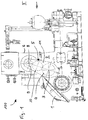
- the pump system 100 comprises a pump unit 1 of conventional design.
- This pump unit 1 comprises a housing 2, from whose side facing the observer one end of a pump drive shaft 3 protrudes. With this shaft end the driven gear 4 of a gear transmission 5 is rotatably connected.
- the gear transmission 5 serves to produce the operative connection of the pump unit with a rotary drive device 6, which comprises a rotation motor R which is only indicated in the drawing, for example hydraulically or electrically driven.
- a shaft end of a driven shaft 8 projects out of the housing 7 of the rotary drive device 6. It is connected via a clutch 12 with a drive wheel 9, which selectively rotatably connects or disconnects the drive wheel 9 with the shaft end.
- the drive wheel 9 is coupled to the output gear 4 via an intermediate gear 10, which is rotatably mounted in a housing 11 of the gear transmission.
- an elastic, non-shiftable coupling can be provided, which permanently connects the shaft end with the drive wheel.
- the toothing of the idler gear 10 is in engagement with the teeth of the drive wheel 9 and the output gear 4.
- the wheels of the gear transmission are helically toothed.
Landscapes
- Engineering & Computer Science (AREA)
- Mechanical Engineering (AREA)
- General Engineering & Computer Science (AREA)
- Geology (AREA)
- Life Sciences & Earth Sciences (AREA)
- Mining & Mineral Resources (AREA)
- General Life Sciences & Earth Sciences (AREA)
- Fluid Mechanics (AREA)
- Environmental & Geological Engineering (AREA)
- Geochemistry & Mineralogy (AREA)
- Physics & Mathematics (AREA)
- Details And Applications Of Rotary Liquid Pumps (AREA)
- Rotary Pumps (AREA)
- Fluid-Driven Valves (AREA)
- Eye Examination Apparatus (AREA)
- Reciprocating Pumps (AREA)
Description
- Die Erfindung betrifft ein Spülflüssigkeitspumpensystem mit einem Pumpenaggregat und mit einer Drehantriebseinrichtung zum Antrieb des Pumpenaggregats. Mit dem Begriff Spülflüssigkeitspumpensystem wird im Rahmen dieser Druckschrift ein Pumpensystem bezeichnet, welches Spülflüssigkeit fördert, die bei dem Vortrieb oder dem Niederbringen von Bohrungen das Bohrloch durchspült. Insbesondere beim Vortrieb oder beim Niederbringen bei Großlochbohrungen wird während des Bohrvorganges Spülflüssigkeit der Bohrung zugeführt. Die Spülflüssigkeit dient einerseits der Schmierung der an der Ortsbrust bzw. an der Bohrungssohle arbeitenden Bohrwerkzeuge sowie der Abstützung der Ortsbrust bzw. der Bohrungswandung. Andererseits kann mit Hilfe der Spülflüssigkeit auch gelöstes Bohrgut aus der Bohrung herausgebracht werden, in dem beispielsweise zentral durch einen hohlen Bohrstrang frische Spülflüssigkeit in dem Bereich der Bohrlochsohle bzw. der Ortsbrust zugeführt wird und somit eine Spülflüssigkeitsströmung erzeugt wird, die gelöstes Bohrgut mitreißt und aus der Bohrung herausbringt.
- Zur Erzeugung der für das Ausbringen erforderlichen Spülflüssigkeitsströmung sind besonders leistungsstarke Pumpensysteme erforderlich. Die Förderleistung derartiger Pumpensysteme liegt regelmäßig im Bereich von maximal 3000 l/min und einem Druck von maximal 50 MPa (500 bar).
- Zum Stand der Technik gehören Pumpensysteme, die sich durch eine besonders kompakte Bauweise auszeichnen, da die das Pumpenaggregat antreibende Drehantriebseinrichtung des Pumpensystems oberhalb des Pumpenaggregats angeordnet und an dessen Gehäuseoberseite angeflanscht ist. Die Drehantriebseinrichtungen haben regelmäßig Leistungen von bis zu 1.700 kW.
- Zum Aufbringen der zum Betreiben von Spülflüssigkeitspumpen erforderlichen relativ hohen Leistung ist es bekannt, an einem Pumpenaggregate zwei oder mehrere Drehantriebseinrichtungen zum Antrieb des einen Pumpenaggregats vorzusehen. So ist beispielsweise aus der
US 2004 / 0219040 A1 , die als Stand der Technik angesehen wird, ein Pumpenaggregat mit zwei Drehantriebseinrichtungen bekannt. - Um die zuvor erwähnte relativ hohe Leistung bzw. das von den Drehantriebseinrichtungen gelieferte Drehmoment auf die Eingangswelle des Pumpenaggregats übertragen zu können, ist es - beispielsweise ebenfalls aus der zuvor genannten
US 2004 / 0219040 A1 - bekannt, die jeweilige Leistung bzw. das jeweils erbringbare Drehmoment der einzelnen Antriebseinrichtungen über eine entsprechende Getriebeanordnung aufzusummieren, um sodann die Gesamtleistung aller Antriebseinrichtungen auf eine Pumpenantriebswelle zu übertragen. Darüber hinaus ist es zur Übertragung der relativ großen Drehmomente - insbesondere bei Kettengetrieben - bekannt, sowohl die Welle des Drehantriebs als auch die Antriebswelle der Pumpe beidseitig aus dem jeweiligen Gehäuse herauszuführen, so dass jede Welle zwei Wellen-Enden aufweist. Auf jedem Wellenende ist rotationsfest ein Kettenrad gelagert. Die Drehmomentübertragung erfolgt dementsprechend durch zwei parallel zueinander verlaufende Ketten. - Nachteilig ist bei derartigen Pumpensystemen, dass der aufgrund der Vielzahl an Drehantriebswellen und/oder der beidseitig laufenden Ketten erforderliche konstruktive Aufwand durch die doppelt benötigten Bauteile und insbesondere durch die 4- bzw. vielfach erforderlichen Wellendurchführungen mit entsprechenden Dichtungsanordnungen hoch ist. Ferner erzeugen die Kettenantriebe im Betrieb einen erheblichen Geräuschpegel.
- Die
GB-A-1 034 058 - Die
US 2004/0060717 A1 betrifft eine Bohrvorrichtung mit einer kompakten Kompressor-Pumpenanordnung. Bei den Pumpen handelt es sich um Hydraulikpumpen, die der Bereitstellung des zur Betätigung der Bohrvorrichtung, beispielsweise Drehen und Stellen des Mastes, mittels Hydraulikzylinder oder Hydraulikmotoren erforderlichen Drucks dient. Der Kompressor dient zur Herstellung von Druckluft, die zum Ausbringen von Bohrgut aus der Bohrung eingesetzt wird. Der Kompressor und die Pumpen sind zu einer Einheit zusammengeflanscht und über Zahnräder mit einer Antriebsachse verbunden, die von einem Rotationsmotor angetrieben wird. Wiederum handelt es sich bei dem Gegenstand dieses Dokuments nicht um eine Spülflüssigkeitspumpe. - Die
US 2004/0028540 A1 bezieht sich auf eine manuell angetriebene Pumpen- oder Kompressoranordnung. Zwar ist bei der in Fig. 3 dargestellten Ausführungsform eine Wirkverbindung zwischen dem manuellen Antrieb und der Pumpen- bzw. Kompressoreinrichtung mittels ineinander greifender Zahnräder bewerkstelligt, einen Zusammenhang mit einem Spülflüssigkeitspumpensystem hat jedoch auch dieses Dokument nicht. - Der Erfindung liegt daher die Aufgabe zu Grunde, ein Pumpensystem zu schaffen, welches zumindest einen der vorgenannten Nachteile nicht aufweist und insbesondere zur Verbesserung der Lebensdauer eine verringerte Anzahl an Dichtungsanordnungen ermöglicht.
- Diese Aufgabe ist durch das in Anspruch 1 wiedergegebene Pumpensystem gelöst.
- Dadurch, dass bei dem erfindungsgemäßen Pumpensystem die Drehantriebseinrichtung über ein ein Antriebs- und ein Abtriebsrad umfassendes Zahnradgetriebe mit dem Pumpenaggregat wirkverbunden ist, wird die einem Kettenantrieb eigene Geräuschentwicklung vermieden. Ferner hat sich überraschenderweise gezeigt, dass es zur Übertragung der zum Betrieb des Pumpenaggregats erforderlichen Leistung und Drehmomente ausreicht, ein Zahnradgetriebe nur auf einer Seite des Pumpensystems vorzusehen. Daher weist das erfindungsgemäße Spülflüssigkeitspumpensystem eine einzige Drehantriebseinrichtung auf. Das Antriebsrad ist über eine elastische Kupplung mit dem Wellenende verbunden.
- Es ist dementsprechend eine Ausführungsform des erfindungsgemäßen Pumpensystems besonders bevorzugt, bei welcher die Drehantriebseinrichtung nur ein einziges Wellenende aufweist, mit dem das Antriebsrad vorzugsweise über eine Kupplung drehverbindbar ist.
- Der von dem Zahnradgetriebe hervorgerufene Geräuschpegel kann weiter gesenkt werden, wenn - wie besonders bevorzugt - die Zahnräder des Zahnradgetriebes schräg verzahnt sind.
- In der Zeichnung ist ein Ausführungsbeispiel eines erfindungsgemäßen Pumpensystems dargestellt.
- Es zeigen:
- Fig. 1
- das Ausführungsbeispiel in einer Seitenansicht sowie
- Fig. 2
- dasselbe Ausführungsbeispiel in einer teilgeschnittenen Ansicht von vorn (Ansicht II in
Fig. 1 ). - Das Pumpensystem 100 umfasst ein Pumpenaggregat 1 herkömmlicher Bauart. Dieses Pumpenaggregat 1 umfasst ein Gehäuse 2, aus dessen dem Betrachter zugewandten Seite ein Ende einer Pumpenantriebswelle 3 herausragt. Mit diesem Wellenende ist das Abtriebsrad 4 eines Zahnradgetriebes 5 drehfest verbunden.
- Das Zahnradgetriebe 5 dient der Herstellung der Wirkverbindung des Pumpenaggregats mit einer Drehantriebseinrichtung 6, die einen in der Zeichnung nur angedeuteten, beispielsweise hydraulisch oder elektrisch angetriebenen, Rotationsmotor R umfasst.
- Die Drehantriebseinrichtung 6 umfasst ein Gehäuse 7, welches am Gehäuse 2 des Pumpenaggregats 1 angeflanscht ist.
- Wiederum auf der dem Betrachter zugewandten Seite ragt ein Wellenende einer angetriebenen Welle 8 aus dem Gehäuse 7 der Drehantriebseinrichtung 6 heraus. Es ist über eine Schaltkupplung 12 mit einem Antriebsrad 9 verbunden, die wahlweise das Antriebsrad 9 drehfest mit dem Wellenende verbindet oder löst. Das Antriebsrad 9 ist mit dem Abtriebsrad 4 über ein Zwischenrad 10 gekoppelt, welches drehbar in einem Gehäuse 11 des Zahnradgetriebes gelagert ist. Anstatt der Schaltkupplung kann auch eine elastische, nicht schaltbare Kupplung vorgesehen sein, die das Wellenende permanent mit dem Antriebsrad verbindet.
- Die Verzahnung des Zwischenrads 10 befindet sich im Eingriff mit den Verzahnungen des Antriebsrades 9 und des Abtriebsrades 4. Zwecks Lärmreduzierung sind die Räder des Zahnradgetriebes schräg verzahnt.
Claims (3)
- Spülflüssigkeitspumpensystem (100)
mit einem Pumpenaggregat (1) und mit einer Drehantriebseinrichtung (6) zum Antrieb des Pumpenaggregats (1),
wobei das Pumpenaggregat ein Gehäuse (2) umfasst, aus dem ein Ende einer Pumpenantriebswelle (3) herausragt,
und wobei eine einzige Drehantriebseinrichtung (6) vorgesehen ist, und die Drehantriebseinrichtung (6) ein Gehäuse (7) umfasst, welches oberhalb des Pumpenaggregats angeordnet und an der Oberseite des Gehäuses (2) des Pumpenaggregats angeflanscht ist, und aus welchem ein Wellenende einer angetriebenen Welle (8) herausragt, und die Drehantriebseinrichtung (6) über ein ein Antriebsrad (9) und ein Abtriebsrad (4) umfassendes Zahnradgetriebe (5) mit dem Pumpenaggregat (1) wirkverbunden ist,
wobei das Antriebsrad (9) über eine elastische Kupplung mit dem Wellenende der Welle (8) verbunden ist, und das Abtriebsrad (4) des Zahnradgetriebes (5) drehfest mit dem aus dem Gehäuse (2) herausragenden Ende der Pumpenantriebswelle (3) verbunden ist. - Spülflüssigkeitspumpensystem nach Anspruch 1,
dadurch gekennzeichnet,
dass die Drehantriebseinrichtung (6) ein einziges Wellenende aufweist, mit dem das Antriebsrad (9) drehverbunden ist. - Spülflüssigkeitspumpensystem nach einem der Ansprüche 1 oder 2,
dadurch gekennzeichnet,
dass die Zahnräder (4, 9) schräg verzahnt sind.
Priority Applications (1)
| Application Number | Priority Date | Filing Date | Title |
|---|---|---|---|
| EP10170292.6A EP2241752B2 (de) | 2005-04-12 | 2006-02-16 | Pumpensystem |
Applications Claiming Priority (2)
| Application Number | Priority Date | Filing Date | Title |
|---|---|---|---|
| DE102005016884A DE102005016884A1 (de) | 2005-04-12 | 2005-04-12 | Pumpensystem |
| PCT/EP2006/001400 WO2006108466A1 (de) | 2005-04-12 | 2006-02-16 | Pumpensystem |
Related Child Applications (2)
| Application Number | Title | Priority Date | Filing Date |
|---|---|---|---|
| EP10170292.6A Division EP2241752B2 (de) | 2005-04-12 | 2006-02-16 | Pumpensystem |
| EP10170292.6A Division-Into EP2241752B2 (de) | 2005-04-12 | 2006-02-16 | Pumpensystem |
Publications (2)
| Publication Number | Publication Date |
|---|---|
| EP1869284A1 EP1869284A1 (de) | 2007-12-26 |
| EP1869284B1 true EP1869284B1 (de) | 2018-12-26 |
Family
ID=36354140
Family Applications (2)
| Application Number | Title | Priority Date | Filing Date |
|---|---|---|---|
| EP06707001.1A Revoked EP1869284B1 (de) | 2005-04-12 | 2006-02-16 | Pumpensystem |
| EP10170292.6A Ceased EP2241752B2 (de) | 2005-04-12 | 2006-02-16 | Pumpensystem |
Family Applications After (1)
| Application Number | Title | Priority Date | Filing Date |
|---|---|---|---|
| EP10170292.6A Ceased EP2241752B2 (de) | 2005-04-12 | 2006-02-16 | Pumpensystem |
Country Status (7)
| Country | Link |
|---|---|
| US (1) | US8186977B2 (de) |
| EP (2) | EP1869284B1 (de) |
| CN (1) | CN101160446B (de) |
| DE (1) | DE102005016884A1 (de) |
| NO (1) | NO343827B1 (de) |
| RU (1) | RU2392414C2 (de) |
| WO (1) | WO2006108466A1 (de) |
Families Citing this family (4)
| Publication number | Priority date | Publication date | Assignee | Title |
|---|---|---|---|---|
| US8920146B2 (en) * | 2005-04-12 | 2014-12-30 | Mhwirth Gmbh | Pump system |
| EP2362116B1 (de) * | 2010-02-18 | 2017-02-01 | Grundfos Management A/S | Zahnrad sowie Pumpenaggregat mit einem solchen Zahnrad |
| JP5934543B2 (ja) * | 2012-03-29 | 2016-06-15 | Kyb株式会社 | 流体圧駆動ユニット |
| GB2584584B8 (en) | 2019-07-11 | 2022-04-13 | Mhwirth As | Hoisting system and method of operation |
Citations (4)
| Publication number | Priority date | Publication date | Assignee | Title |
|---|---|---|---|---|
| US879560A (en) | 1905-10-05 | 1908-02-18 | Daniel F Lepley | Triplex pump. |
| US5246355A (en) | 1992-07-10 | 1993-09-21 | Special Projects Manufacturing, Inc. | Well service pumping assembly |
| US20040219042A1 (en) | 2003-04-30 | 2004-11-04 | Vladimir Kugelev | Manifold assembly for reciprocating pump |
| US20040219040A1 (en) * | 2003-04-30 | 2004-11-04 | Vladimir Kugelev | Direct drive reciprocating pump |
Family Cites Families (17)
| Publication number | Priority date | Publication date | Assignee | Title |
|---|---|---|---|---|
| US2899247A (en) * | 1959-08-11 | Feed water pump | ||
| US2131749A (en) * | 1936-06-29 | 1938-10-04 | Homestead Valve Mfg Co | Pump |
| US2331513A (en) * | 1937-12-18 | 1943-10-12 | Emsco Derrick & Equip Co | Slush pump |
| US2755739A (en) * | 1953-07-20 | 1956-07-24 | Lever Brothers Ltd | Proportioning pump |
| US2883874A (en) * | 1958-02-03 | 1959-04-28 | Halliburton Oil Well Cementing | Heavy duty pump |
| GB1034058A (en) * | 1964-05-21 | 1966-06-29 | William Stewart Robinson | Improvements in sun-and-planet gearing |
| US4118151A (en) * | 1974-04-03 | 1978-10-03 | Tokico Ltd. | Pump device |
| US4009971A (en) * | 1974-06-07 | 1977-03-01 | Binks Manufacturing Company | Electric motor-driven, double-acting pump having pressure-responsive actuation |
| US4435990A (en) * | 1980-09-11 | 1984-03-13 | Chalmers Samuel A | Power take off gear box |
| CA1205327A (en) * | 1981-12-04 | 1986-06-03 | Gordon M. Sommer | Oil well pump drive |
| RU5224U1 (ru) * | 1997-02-26 | 1997-10-16 | Андрей Петрович Донодин | Насосный агрегат |
| RU2146777C1 (ru) * | 1998-08-12 | 2000-03-20 | Валерий Николаевич Петрухин | Насосный агрегат |
| JP2002526718A (ja) * | 1998-10-01 | 2002-08-20 | ペック,ジュリアン,クロード | 手動式ポンプ又はコンプレッサ |
| CN2385075Y (zh) * | 1999-08-23 | 2000-06-28 | 石油地球物理勘探局装备制造总厂 | 石油地质勘探钻机用泥浆泵 |
| US6981855B2 (en) * | 2002-09-30 | 2006-01-03 | Sandvik Ab | Drilling rig having a compact compressor/pump assembly |
| CN2612816Y (zh) * | 2003-03-30 | 2004-04-21 | 泰安市水利机械厂 | 高压柱塞泥浆泵 |
| US20040213677A1 (en) * | 2003-04-24 | 2004-10-28 | Matzner Mark D. | Monitoring system for reciprocating pumps |
-
2005
- 2005-04-12 DE DE102005016884A patent/DE102005016884A1/de not_active Ceased
-
2006
- 2006-02-16 EP EP06707001.1A patent/EP1869284B1/de not_active Revoked
- 2006-02-16 US US11/918,310 patent/US8186977B2/en active Active
- 2006-02-16 EP EP10170292.6A patent/EP2241752B2/de not_active Ceased
- 2006-02-16 WO PCT/EP2006/001400 patent/WO2006108466A1/de not_active Ceased
- 2006-02-16 CN CN2006800120030A patent/CN101160446B/zh not_active Expired - Fee Related
- 2006-02-16 RU RU2007141682/03A patent/RU2392414C2/ru active
-
2007
- 2007-10-09 NO NO20075108A patent/NO343827B1/no unknown
Patent Citations (4)
| Publication number | Priority date | Publication date | Assignee | Title |
|---|---|---|---|---|
| US879560A (en) | 1905-10-05 | 1908-02-18 | Daniel F Lepley | Triplex pump. |
| US5246355A (en) | 1992-07-10 | 1993-09-21 | Special Projects Manufacturing, Inc. | Well service pumping assembly |
| US20040219042A1 (en) | 2003-04-30 | 2004-11-04 | Vladimir Kugelev | Manifold assembly for reciprocating pump |
| US20040219040A1 (en) * | 2003-04-30 | 2004-11-04 | Vladimir Kugelev | Direct drive reciprocating pump |
Non-Patent Citations (7)
| Title |
|---|
| "Taschenbuch für den Maschinenbau", 1997, article HÖHN, ET AL.: "Chapter 8 Zahnradgetriebe Gearing", pages: 1 - 3, XP055632106 |
| ANONYMOUS: "Continuous duty pumps", COMPOSITE CATALOG OF OIL FIELD EQUIPMENT AND SERVICES, vol. 1, 1998, pages 840 - 841, XP055632061 |
| ANONYMOUS: "National-oilwell plunger pumps", COMPOSITE CATALOG OF OIL FIELD EQUIPMENT AND SERVICES, vol. 2, 1996, pages 1716 - 1719, XP055632070 |
| ANONYMOUS: "TGH Triplex Well Servicing Pump 400 HP, 8 STROKE", GARDENER DENCER, BULLETIN 4-202, VERSION 2, September 2001 (2001-09-01), pages 1 - 2, XP055632045 |
| ANONYMOUS: "Triplex Mud Pumps", COMPOSITE CATALOG OF OILFIELD EQUIPMENT & SERVICES, 2002, pages 770 - 771, XP055632089 |
| ANONYMOUS: "Triplex pumps", COMPOSITE CATALOG OF OIL FIELD EQUIPMENT & SERVICES, vol. 2, 1998, pages 1 - 4, XP055632086 |
| ANONYMOUS: "Well servicing pumps", COMPOSITE CATALOG OF OIL FIELD EQUIPMENT AND SERVICES, vol. 2, 1986, pages 1 - 2, XP055632051 |
Also Published As
| Publication number | Publication date |
|---|---|
| NO20075108L (no) | 2007-11-07 |
| NO343827B1 (no) | 2019-06-17 |
| EP2241752A3 (de) | 2015-12-09 |
| CN101160446A (zh) | 2008-04-09 |
| EP2241752B1 (de) | 2019-06-12 |
| RU2007141682A (ru) | 2009-05-20 |
| EP1869284A1 (de) | 2007-12-26 |
| EP2241752A2 (de) | 2010-10-20 |
| US20090038852A1 (en) | 2009-02-12 |
| US8186977B2 (en) | 2012-05-29 |
| CN101160446B (zh) | 2013-07-03 |
| RU2392414C2 (ru) | 2010-06-20 |
| EP2241752B2 (de) | 2022-07-20 |
| WO2006108466A1 (de) | 2006-10-19 |
| DE102005016884A1 (de) | 2006-10-19 |
Similar Documents
| Publication | Publication Date | Title |
|---|---|---|
| EP0866210B1 (de) | Verfahren zum Betreiben eines Arbeitsmoduls und Vorrichtung zur Übertragung von Drehmomenten und Drehzahlen eines Antriebsaggregats in das Arbeitsmodul | |
| DE2047587A1 (de) | Entkupplungsvorrichtung | |
| DE2654197A1 (de) | Fluid-motor-anordnung | |
| EP2430284A2 (de) | Zug- und druckvorrichtung | |
| DE19957791A1 (de) | Hydraulischer Bohrantrieb | |
| DE19581945B4 (de) | Antriebskopf für eine Bohrlochpumpe | |
| EP1869284B1 (de) | Pumpensystem | |
| DE2824441C2 (de) | Erdbohrer | |
| DE112013004544T5 (de) | Antriebseinheit für Kettenantriebe im Bergbau | |
| DE4113986A1 (de) | Hydraulisch angetriebener bohrmotor zum tiefbohren | |
| DE2733199A1 (de) | Bohrvorrichtung zum einbringen von tiefbohrungen in erdreich, gestein u.dgl. | |
| DE2541838C3 (de) | Walzenschrämmaschine bzw. Vortriebsmaschine für den Untertagebergbau | |
| DE19955262A1 (de) | Mehrachsige Gaskompressions-Pumpvorrichtung | |
| DE4402487A1 (de) | Kompaktbohreinheit für gegenläufiges Überlagerungsbohren auf Kleinbohrgeräten | |
| DE2547934A1 (de) | Kraftgeschaltetes mehrganggetriebe | |
| DE330888C (de) | Tragbare Antriebsmaschine | |
| DE102019219048A1 (de) | Kraftfahrzeuggetriebe mit einem Nebenabtrieb | |
| DE102019219046A1 (de) | Kraftfahrzeuggetriebe mit einem Nebenabtrieb | |
| DE2528927C3 (de) | Umsteuerbare Zahnradmotoren | |
| AT510314B1 (de) | Schneidvorrichtung für verfahrbare abbaumaschinen für den unterwassereinsatz | |
| AT203435B (de) | Tiefbohranlage mit mehreren Antriebsmotoren | |
| DE19617213C1 (de) | Biegestabverbindung | |
| AT211764B (de) | Hydraulische Turbine für Drehbohrantriebe in Tiefbohrlöchern und Verfahren zu ihrem Betrieb | |
| DE1023682B (de) | Stufenlos regelbares, mit einem Stirnraederwechselgetriebe vereinigtes hydrostatisches Getriebe fuer Fahrzeuge, insbesondere Schlepper | |
| WO2009156500A1 (de) | Getriebelose kolbenpumpe |
Legal Events
| Date | Code | Title | Description |
|---|---|---|---|
| PUAI | Public reference made under article 153(3) epc to a published international application that has entered the european phase |
Free format text: ORIGINAL CODE: 0009012 |
|
| 17P | Request for examination filed |
Effective date: 20071018 |
|
| AK | Designated contracting states |
Kind code of ref document: A1 Designated state(s): DE IT |
|
| 17Q | First examination report despatched |
Effective date: 20080226 |
|
| RBV | Designated contracting states (corrected) |
Designated state(s): DE IT |
|
| DAX | Request for extension of the european patent (deleted) | ||
| TPAC | Observations filed by third parties |
Free format text: ORIGINAL CODE: EPIDOSNTIPA |
|
| RAP1 | Party data changed (applicant data changed or rights of an application transferred) |
Owner name: AKER WIRTH GMBH |
|
| TPAC | Observations filed by third parties |
Free format text: ORIGINAL CODE: EPIDOSNTIPA |
|
| TPAC | Observations filed by third parties |
Free format text: ORIGINAL CODE: EPIDOSNTIPA |
|
| RAP1 | Party data changed (applicant data changed or rights of an application transferred) |
Owner name: MHWIRTH GMBH |
|
| STAA | Information on the status of an ep patent application or granted ep patent |
Free format text: STATUS: EXAMINATION IS IN PROGRESS |
|
| GRAP | Despatch of communication of intention to grant a patent |
Free format text: ORIGINAL CODE: EPIDOSNIGR1 |
|
| STAA | Information on the status of an ep patent application or granted ep patent |
Free format text: STATUS: GRANT OF PATENT IS INTENDED |
|
| INTG | Intention to grant announced |
Effective date: 20180918 |
|
| GRAS | Grant fee paid |
Free format text: ORIGINAL CODE: EPIDOSNIGR3 |
|
| GRAA | (expected) grant |
Free format text: ORIGINAL CODE: 0009210 |
|
| STAA | Information on the status of an ep patent application or granted ep patent |
Free format text: STATUS: THE PATENT HAS BEEN GRANTED |
|
| AK | Designated contracting states |
Kind code of ref document: B1 Designated state(s): DE IT |
|
| REG | Reference to a national code |
Ref country code: DE Ref legal event code: R096 Ref document number: 502006016140 Country of ref document: DE |
|
| REG | Reference to a national code |
Ref country code: DE Ref legal event code: R026 Ref document number: 502006016140 Country of ref document: DE |
|
| PLBI | Opposition filed |
Free format text: ORIGINAL CODE: 0009260 |
|
| 26 | Opposition filed |
Opponent name: BENTEC GMBH DRILLING & OILFIELD SYSTEMS Effective date: 20190813 |
|
| PLAX | Notice of opposition and request to file observation + time limit sent |
Free format text: ORIGINAL CODE: EPIDOSNOBS2 |
|
| PLBB | Reply of patent proprietor to notice(s) of opposition received |
Free format text: ORIGINAL CODE: EPIDOSNOBS3 |
|
| PGFP | Annual fee paid to national office [announced via postgrant information from national office to epo] |
Ref country code: IT Payment date: 20210128 Year of fee payment: 16 |
|
| PGFP | Annual fee paid to national office [announced via postgrant information from national office to epo] |
Ref country code: DE Payment date: 20210120 Year of fee payment: 16 |
|
| REG | Reference to a national code |
Ref country code: DE Ref legal event code: R103 Ref document number: 502006016140 Country of ref document: DE Ref country code: DE Ref legal event code: R064 Ref document number: 502006016140 Country of ref document: DE |
|
| REG | Reference to a national code |
Ref country code: DE Ref legal event code: R082 Ref document number: 502006016140 Country of ref document: DE Representative=s name: ZACCO PATENTANWALTS- UND RECHTSANWALTSGESELLSC, DE |
|
| RDAF | Communication despatched that patent is revoked |
Free format text: ORIGINAL CODE: EPIDOSNREV1 |
|
| RDAG | Patent revoked |
Free format text: ORIGINAL CODE: 0009271 |
|
| STAA | Information on the status of an ep patent application or granted ep patent |
Free format text: STATUS: PATENT REVOKED |
|
| 27W | Patent revoked |
Effective date: 20210720 |