EP1867817A1 - Connecting rod fastener - Google Patents
Connecting rod fastener Download PDFInfo
- Publication number
- EP1867817A1 EP1867817A1 EP07104195A EP07104195A EP1867817A1 EP 1867817 A1 EP1867817 A1 EP 1867817A1 EP 07104195 A EP07104195 A EP 07104195A EP 07104195 A EP07104195 A EP 07104195A EP 1867817 A1 EP1867817 A1 EP 1867817A1
- Authority
- EP
- European Patent Office
- Prior art keywords
- bolt
- drive rod
- latch
- window
- locking cam
- Prior art date
- Legal status (The legal status is an assumption and is not a legal conclusion. Google has not performed a legal analysis and makes no representation as to the accuracy of the status listed.)
- Granted
Links
Images


Classifications
-
- E—FIXED CONSTRUCTIONS
- E05—LOCKS; KEYS; WINDOW OR DOOR FITTINGS; SAFES
- E05B—LOCKS; ACCESSORIES THEREFOR; HANDCUFFS
- E05B59/00—Locks with latches separate from the lock-bolts or with a plurality of latches or lock-bolts
-
- E—FIXED CONSTRUCTIONS
- E05—LOCKS; KEYS; WINDOW OR DOOR FITTINGS; SAFES
- E05C—BOLTS OR FASTENING DEVICES FOR WINGS, SPECIALLY FOR DOORS OR WINDOWS
- E05C9/00—Arrangements of simultaneously actuated bolts or other securing devices at well-separated positions on the same wing
- E05C9/02—Arrangements of simultaneously actuated bolts or other securing devices at well-separated positions on the same wing with one sliding bar for fastening when moved in one direction and unfastening when moved in opposite direction; with two sliding bars moved in the same direction when fastening or unfastening
- E05C9/026—Arrangements of simultaneously actuated bolts or other securing devices at well-separated positions on the same wing with one sliding bar for fastening when moved in one direction and unfastening when moved in opposite direction; with two sliding bars moved in the same direction when fastening or unfastening comprising key-operated locks, e.g. a lock cylinder to drive auxiliary deadbolts or latch bolts
-
- E—FIXED CONSTRUCTIONS
- E05—LOCKS; KEYS; WINDOW OR DOOR FITTINGS; SAFES
- E05B—LOCKS; ACCESSORIES THEREFOR; HANDCUFFS
- E05B17/00—Accessories in connection with locks
- E05B17/20—Means independent of the locking mechanism for preventing unauthorised opening, e.g. for securing the bolt in the fastening position
- E05B17/2007—Securing, deadlocking or "dogging" the bolt in the fastening position
- E05B17/203—Securing, deadlocking or "dogging" the bolt in the fastening position not following the movement of the bolt
- E05B17/2038—Securing, deadlocking or "dogging" the bolt in the fastening position not following the movement of the bolt moving rectilinearly
-
- E—FIXED CONSTRUCTIONS
- E05—LOCKS; KEYS; WINDOW OR DOOR FITTINGS; SAFES
- E05B—LOCKS; ACCESSORIES THEREFOR; HANDCUFFS
- E05B63/00—Locks or fastenings with special structural characteristics
- E05B63/18—Locks or fastenings with special structural characteristics with arrangements independent of the locking mechanism for retaining the bolt or latch in the retracted position
Definitions
- the invention relates to an espagnolette with a lockable from a back-closed position in a vor foundede position latch, and with a transversely movable from a release position into a locking position drive rod, wherein the prefix of the bolt in the release position of the drive rod according to a profile engagement of a reduced in width Blocking portion of a latch passage window of the drive rod is blocked in a broad side recess of the bolt, and the pre-locked latch with a locking cam blocks a return displacement of the drive rod from its locked position.
- the drive rod has a latch passage window.
- This latch passage window has a blocking portion which is formed by two V-shaped converging portions of the window wall. In the release position of the drive rod these sections of the window are in broad side recesses of the bolt, so that the bolt is positively locked against a transverse displacement to the drive rod. This positive connection between the drive rod and bolt is canceled by a downward displacement of the drive rod. After that can be brought by means of closing operation of a profile cylinder of the bolt in a pre-closed position.
- a locking cam on the bolt has entered a rear recess of a driving rod connecting slide and thus blocks its rearward displacement.
- a push-pull cam of the espagnolette slide comes against the detent cam.
- the drive rod is there motion-locked in the locked on both sides lock position.
- the invention has the object of providing a grasping of a grasping of a grasping of a grasping of a grasping of a grasping of a grasping of a grasping of a grasping of a grasping of a grasping of a grasping of a grasping of a grasping of a grasping of a grasping of a grasping of a grasping of a grasping of a grasping of a grasping of a grasping of a grasping of a grasping of a grasping of a grasping of a grasping of a grasping of a grasping of a grasping of a grasping of a grasping of a grasping of a grasping of a grasping of a grasping of a grasping of a grasping of a grasping of a grasping of a grasping of a grasping of a grasping of a grasping of a grasping of a grasping of a grasping of a grasping of a grasping of a
- each claim represents an independent solution to the problem.
- the claim 1 provides initially and essentially before that the blocking portion of the bolt passage window is formed by a step.
- the blocking section is formed by two sections of a window wall as in the prior art. These are preferably formed by two opposing projections.
- the latter can have a rectangular contour, so that two end faces of the projections run parallel to one another. Two further marginal edges of the rectangular contour can be aligned with each other and extend transversely to the extension direction of the drive rod.
- the step is formed in a simple manner, in front of which the locking cam of the fully locked bolt is located. In this position, a locked on both sides lock position is also locked motion.
- the drive rod can be moved to the release position. This is possible even after a slight displacement of the bolt from its pre-closed position, since the locking cam only comes in the final phase of the VorQueryiolo before the blocking portion of the bolt window.
- the drive rod can only be moved to the release position when the latch is completely closed. Then, namely, the two projections can enter into corresponding, near the free end of the bolt head arranged broad side recesses of the bolt head.
- the latch passage window has another portion which lies beyond the two opposing protrusions. The projections thus form a Sidecut of a window. This further window portion forms the passage opening for a trap, which is retractable by pressing a pusher.
- the drive nut has an arm with which it acts on the drive rod or on a drive rod connection slide.
- the drive nut has a second arm, which is held by a spring assembly in a neutral center position.
- the bolt tail has a greater width than the bolt head. In this respect, the bolt forms a step.
- the locking cam is part of this level. He has a broadside increase and thus lies in the direction of displacement of the drive rod in its release position in front of the bolt head.
- the castle has a castle floor and a castle ceiling. Both are spaced apart and consist of stamped and bent parts. Between Schlossêt and Schlossdecke there is the Schlosseinunde.
- This lock has a latch 4. This has a latch tail with an end projection on which an actuating arm 1 attacks.
- the trap extends through a portion 23 'of a window 23 of a drive rod 9, the back of a cuff 27 is guided.
- the cuff 27 has a the plan view of the case head 4 'adapted window in which the case head 4' is guided.
- the other arm of the leg spring 3 which forms a latch spring, is supported on a pin fixed to the housing. At this pin 28 and the actuating arm 1 is supported.
- the actuating arm 1 is mounted on a nut 2.
- This nut 2 has a square opening for the passage of a pusher mandrel. From the nut 2 protrude in a diametrical opposite transfer cams 18.
- These driving cams 18 are each in driving recesses 19 which are associated with the actuating arm 1.
- the width of the Mitéesaussparungen 19 is greater than the width of the driving cam 18. This allows the nut 2 rotate by a certain angle, without the operating arm is nadomit towed.
- Join the driving cams 18 but against the wall of the driving recess 19 and the nut 2 further example. Clockwise rotated so pivots the rotational movement of the nut 2, the actuating arm 1, which engages the rear projection of the latch tail. Along with this pivotal movement of the actuating arm 1, the case 4 is withdrawn.
- the nut 2 is a control arm 5 is formed.
- This control arm 5 has the shape of a tooth of a gear.
- the sides pointing away flanks of the Control arm 5 are involute curved and are at attack edges 10,11.
- the two attack flanks 10,11 are spaced from each other by the width of the control arm 5 and face each other.
- the attack flanks 10, 11 are formed by projections 12,13.
- Each projection 12, 13 belongs to a slide 7, 8 of a spring assembly.
- the slides can be made of plastic or metal. They are preferably molded molded parts.
- the slides 7, 8 each form a pot-like recess 16.
- the two pot-like recesses 16 of the two slides 7, 8 face each other and each store one end of a compression spring 6, with which the two slides 7, 8 are acted upon away from each other.
- the two slides 7, 8 are compressed by a U-shaped retaining clip 17.
- the U-legs of the retaining clip 17 forms a contact surface for the side walls of the slide 7, 8.
- the headband 17 is not shown with positive locking means connected to the lock housing.
- each slide 7, 8 forms a web 14, which is the extension of a side wall of the cup-like depression 16.
- Each of the two webs 14, 15 has a direction transverse to the displacement direction of the slider or to the direction of extension of the compression spring 6 protruding projection 12, 13.
- the projections 12, 13 form the two attack flanks 10,11.
- each of the two slides 7, 8 forms guide extensions 30. These protrude in the assembled state into guide slots of either the lock bottom or the lock cover, so that the two slides 7, 8 are linearly guided.
- the two webs 14,15 partially run side by side.
- the protruding from the webs projections 12,13 extend partially over the web 14, 15 of the other slide 7, 8, so that the two flanks 10,11 in the direction of movement of the slide 7, 8 are opposite.
- the nut 2 engages with a further driving arm which also rests with motion clearance in driving recesses, on a espagnolette 20.
- This espagnolette arm 20 acts on a drive rod slide 29, which is positively coupled to the drive rod 9.
- the drive rod 9 is of a coupling extension of the espagnolette 29, which engages in a coupling window of the drive rod 9, moved.
- the drive rod 9 has an elongated window 23 through which the substantially rectangular plan 21 having a bar occurs.
- the two opposite broad sides of the bolt head 21 ' form recesses 24. These broad side recesses 24 are grooves which are slightly removed from the end face of the bolt head 21'.
- the bolt head 21 ' forms a step 26.
- This stage which is located in the transition region to the bolt tail, has on its lower side a broadside projection which forms a locking cam 25.
- the latch can be actuated by a lock cylinder, via the drive nut 31. For this purpose, levers not shown are provided.
- the drive rod 9 is shown in the locked position.
- the window 23 of the drive rod 9 has a sidecut, which are formed by two opposing blocking projections 22. These rectangular blocking projections form with a rectangular narrow side in each case a step 22 ', which extends transversely to the extension direction of the drive rod 9.
- the two mutually aligned steps 22 'thus extend transversely to the displacement direction of the drive rod.
- the two blocking protrusions 22 have end flanks 22 "which are spaced apart from one another by less than the width of the bolt head 21 ', but the distance between the two end flanks 22" is greater than the distance between the two bottoms of the broad side recesses 24, so that the blocking protrusions 22 can dive by upward movement of the drive rod 9 from the locking position shown in Figure 2 in the broad side recesses 24, as shown in Figure 5, in which the drive rod is displaced into a release position.
- the window 23 continues in a fall passage window 23 ', in which the head 4' of the trap 4 rests.
- the latch 21 is actuated by the drive nut 31, for example, by a lock cylinder. He can be extended by turning the drive nut 31 so far until the step 26 abuts the drive rod 9 and the cuff 27.
- the blocking projection 22 lies in the path of movement of the locking cam 25. This has the consequence that the locking head 21 'indeed can be relocated. However, the latch 21 can not be completely closed. This can be felt, for example, by a lock cylinder during the rotational displacement of the drive nut 31. The user can thus determine by locking operation or actuation of the device for a lock cylinder 31, whether the drive rod 9 is fully extended to the locking position, since only then the bolt 21 can be completely preconnected.
Abstract
Description
Die Erfindung betrifft einen Treibstangenverschluss mit einem aus einer rückgeschlossenen Stellung in eine vorgeschlossene Stellung vorschließbaren Riegel, und mit einer quer dazu von einer Freigabestellung in eine Verriegelungsstellung verlagerbaren Treibstange, wobei der Vorschluss des Riegels in der Freigabestellung der Treibstange zufolge eines Profileingriffs eines in der Weite verminderten Blockierabschnitts eines Riegeldurchtrittsfensters der Treibstange in eine Breitseitenaussparung des Riegels blockiert ist, und der vorgeschlossene Riegel mit einem Arretierungsnocken eine Zurückverlagerung der Treibstange aus ihrer Verriegelungsstellung blockiert.The invention relates to an espagnolette with a lockable from a back-closed position in a vorgeschlossene position latch, and with a transversely movable from a release position into a locking position drive rod, wherein the prefix of the bolt in the release position of the drive rod according to a profile engagement of a reduced in width Blocking portion of a latch passage window of the drive rod is blocked in a broad side recess of the bolt, and the pre-locked latch with a locking cam blocks a return displacement of the drive rod from its locked position.
Ein Treibstangenverschluss der vorbezeichneten Art ist aus der
Der Erfindung liegt die Aufgabe zugrunde, ein Treibstangeschloss mit der zuvor beschriebenen Funktionsfähigkeit herstellungstechnisch einfach auszubilden.The invention has the object of providing a Treibstangeschloss with the above-described functionality manufacturing technology simple form.
Gelöst wird die Aufgabe durch die in den Ansprüchen angegebene Erfindung, wobei jeder Anspruch eine eigenständige Lösung der Aufgabe darstellt.The object is achieved by the invention specified in the claims, each claim represents an independent solution to the problem.
Der Anspruch 1 sieht zunächst und im wesentlichen vor, dass der Blockierabschnitt des Riegeldurchtrittsfensters von einer Stufe ausgebildet wird. Vor dieser Stufe liegt der Arretierungsnocken des vollständig vorgeschlossenen Riegels. Der Blockierabschnitt wird wie auch beim Stand der Technik von zwei Abschnitten einer Fensterwandung gebildet. Diese werden bevorzugt von zwei sich gegenüberliegenden Vorsprüngen ausgebildet. Letztere können eine Rechteckkontur aufweisen, so dass zwei Stirnseiten der Vorsprünge parallel zueinander verlaufen. Zwei weitere Randkanten der Rechteckkontur können miteinander fluchten und quer zur Erstreckungsrichtung der Treibstange verlaufen. Auf diese Art wird in einfacher Weise die Stufe ausgebildet, vor welcher der Arretierungsnocken des vollständig vorgeschlossenen Riegels liegt. In dieser Stellung ist ebenfalls eine beidseitig vorgeschlossene Schlossstellung bewegungsgesperrt. Erst wenn der Riegel aus seiner vorgeschlossenen Stellung zurückgeschlossen wird, kann die Treibstange in die Freigabestellung verlagert werden. Dies ist bereits nach einer geringfügigen Verlagerung des Riegels aus seiner vorgeschlossenen Stellung möglich, da der Arretierungsnocken erst in der Endphase der Vorschlussbewegung vor den Blockierabschnitt des Riegelfensters tritt. Die Treibstange kann aber erst bei vollständig zurückgeschlossenem Riegel in die Freigabestellung verlagert werden. Dann können nämlich die beiden Vorsprünge in entsprechende, nahe dem freien Ende des Riegelkopfes angeordnete Breitseitenaussparungen des Riegelkopfes eintreten. Das Riegeldurchtrittsfenster besitzt einen weiteren Abschnitt, welcher jenseits der beiden sich gegenüberliegenden Vorsprünge liegt. Die Vorsprünge bilden somit eine Taillierung eines Fensters. Dieser weitere Fensterabschnitt bildet die Durchtrittsöffnung für eine Falle, die durch Betätigung eines Drückers zurückziehbar ist. Mit diesem Drücker kann auch die Treibstange zwischen Freigabestellung und Verriegelungsstellung hin- und hergeschwenkt werden. Dies erfolgt einerseits durch eine Drehung der Antriebsnuss durch einen Schließzylinder im Uhrzeigersinn und andererseits durch eine Drehung der Antriebsnuss im Gegenuhrzeigersinn. Die Antriebsnuss besitzt einen Arm, mit dem sie an der Treibstange bzw. an einen Treibstangenanschlussschieber angreift. Die Antriebsnuss besitzt einen zweiten Arm, der von einem Federpaket in einer neutralen Mittelstellung gehalten wird. Der Riegelschwanz besitzt eine größere Breite als der Riegelkopf. Insofern bildet der Riegel eine Stufe aus. Der Blockiernocken ist Teil dieser Stufe. Er besitzt eine Breitseitenerhöhung und liegt somit in Verlagerungsrichtung der Treibstange in ihre Freigabestellung vor dem Riegelkopf. Dies hat zur Folge, dass sich die Treibstange bei vollständig vorgeschlossenem Riegel so gut wie nicht bewegen lässt. Wird der Riegel geringfügig aus der vollständig vorgeschlossenen Stellung zurückgezogen, so tritt der Arretierungsnocken aus der Bewegungsbahn des Blockierabschnittes des Riegeldurchtrittsfensters, so dass die Treibstange geringfügig in Richtung ihrer Freigabestellung verlagerbar ist. Ihre Freigabestellung kann die Treibstange aber erst erreichen, wenn der Riegel vollständig zurückgezogen ist, da anderenfalls der Blockierabschnitt vor den Riegelkopf treten würde. Eine Weiterverlagerung der Treibstange wäre dann blockiert. Erst bei vollständig zurückgeschlossenem Riegel fluchten dessen Breitseitenaussparungen mit den beiden sich gegenüberliegenden, den Blockierabschnitt ausbildenden Vorsprüngen. Diese können dann in die Breitseitenaussparungen eintreten. Einhergehend mit diesem Formschlusseingriff wird dann aber auch die Vorschließbarkeit des Riegels blockiert.The
Ein Ausführungsbeispiel der Erfindung wird nachfolgend anhand beigefügter Zeichnungen erläutert. Es zeigen
- Fig. 1
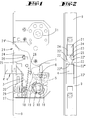
- ein Treibstangenschloss in der Breitseitenansicht mit bereichsweise entfernter Schlossdecke mit zurückgeschlossenem Riegel und in Verriegelungsstellung stehender Treibstange;
- Fig. 2
- eine Seitenansicht auf das Schloss in einem Betriebszustand gemäß Fig. 1 bei entfernter Stulpe;
- Fig. 3
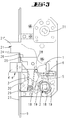
- eine Darstellung gemäß Fig. 1 mit vorgeschlossenem Riegel;
- Fig. 4
- eine Darstellung gemäß Fig. 1 mit zurückgeschlossenem Riegel und in Freigabestellung stehender Treibstange;
- Fig. 5
- eine Seitenansicht auf das Schloss in einem Betriebszustand gemäß Fig. 4 bei entfernter Stulpe;
- Fig. 6
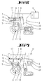
- die Nuss des Schlosses nebst Falle und einem die Nuss in einer neutralen Mittelstellung haltenden Federpaket in einer gegenüber der
Figur 1 umgewendeten Stellung; - Fig. 7
- eine Darstellung gemäß
Figur 6 mit in Fallenrückzugsrichtung verlagerter Antriebsnuss; - Fig. 8
- eine Folgedarstellung zu Fig. 7 mit vom Federpaket in die neutrale Mittelstellung zurückverlagerter Nuss;
- Fig. 9
- eine Folgedarstellung zu Fig. 8 mit in Gegenrichtung verdrehter Nuss;
- Fig. 10
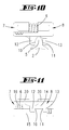
- das Federpaket in vergrößerter Darstellung in Ansicht und
- Fig. 11
- das Federpaket gemäß Fig. 10 in einer Draufsicht.
- Fig. 1
- a espagnolette lock in broadside view with partially removed lock cover with locked back latch and in locking position standing drive rod;
- Fig. 2
- a side view of the lock in an operating condition shown in Figure 1 with removed cuff.
- Fig. 3
- a representation of Figure 1 with vorgeschlossenem latch.
- Fig. 4
- a representation of Figure 1 with zurückgeschlossenem latch and standing in the release position drive rod.
- Fig. 5
- a side view of the castle in an operating condition shown in Figure 4 with removed cuff.
- Fig. 6
- the nut of the lock together with the case and a spring package holding the nut in a neutral central position in a position turned over in relation to FIG. 1;
- Fig. 7
- a representation according to Figure 6 with displaced in Fallenrückzugsrichtung drive nut;
- Fig. 8
- a sequence to Fig. 7 with the spring package back to the neutral center position shifted nut;
- Fig. 9
- a sequence to Figure 8 with in the opposite direction twisted nut.
- Fig. 10
- the spring package in an enlarged view in view and
- Fig. 11
- the spring assembly of FIG. 10 in a plan view.
Das Schloss besitzt einen Schlossboden und eine Schlossdecke. Beide sind voneinander beabstandet und bestehen aus Stanzbiegeteilen. Zwischen Schlossboden und Schlossdecke befindet sich das Schlosseingerichte. Zu diesem Schlosseingerichte gehört eine Falle 4. Diese besitzt einen Fallenschwanz mit einem endseitigen Vorsprung, an dem ein Betätigungsarm 1 angreift. Die Falle durchragt einen Abschnitt 23'eines Fensters 23 einer Treibstange 9, die rückwärtig einer Stulpe 27 geführt ist. Die Stulpe 27 besitzt ein dem Grundriss des Fallenkopfes 4' angepasstes Fenster, in welchem der Fallenkopf 4' geführt ist. Am Fallenkopf 4' greift rückwärtig der Arm einer Schenkelfeder 3 an. Der andere Arm der Schenkelfeder 3, die eine Fallenfeder ausbildet, stützt sich an einem gehäusefesten Zapfen ab. An diesem Zapfen 28 stützt sich auch der Betätigungsarm 1 ab.The castle has a castle floor and a castle ceiling. Both are spaced apart and consist of stamped and bent parts. Between Schlossboden and Schlossdecke there is the Schlosseingerichte. This lock has a
Der Betätigungsarm 1 ist auf einer Nuss 2 gelagert. Diese Nuss 2 besitzt eine Vierkantöffnung zum Durchstecken eines Drückerdornes. Von der Nuss 2 ragen in diametraler Gegenüberlage Mitnahmenocken 18 ab. Diese Mitnahmenocken 18 liegen jeweils in Mitnahmeaussparungen 19, die dem Betätigungsarm 1 zugeordnet sind. Die Weite der Mitnahmeaussparungen 19 ist größer als die Weite des Mitnahmenockens 18. Hierdurch lässt sich die Nuss 2 um einen bestimmten Winkelbetrag drehen, ohne dass der Betätigungsarm drehmitgeschleppt wird. Treten die Mitnahmenocken 18 aber gegen die Wandung der Mitnahmeaussparung 19 und wird die Nuss 2 weiter bspw. im Uhrzeigersinn gedreht, so verschwenkt die Drehbewegung der Nuss 2 den Betätigungsarm 1, der an dem rückwärtigen Vorsprung des Fallenschwanzes angreift. Einhergehend mit dieser Schwenkbewegung des Betätigungsarmes 1 wird die Falle 4 zurückgezogen.The
Der Nuss 2 ist ein Steuerarm 5 angeformt. Dieser Steuerarm 5 besitzt die Form eines Zahnes eines Zahnrades. Die voneinander weg weisenden Flanken des Steuerarmes 5 sind evolventenartig gekrümmt und liegen an Angriffsflanken 10,11. Die beiden Angriffsflanken 10,11 sind um die Weite des Steuerarmes 5 voneinander beabstandet und weisen aufeinander zu.The
Die Angriffsflanken 10, 11 werden von Vorsprüngen 12,13 ausgebildet. Jeder Vorsprung 12, 13 gehört zu einem Schieber 7, 8 eines Federpaketes. Die Schieber können aus Kunststoff oder Metall bestehen. Sie sind bevorzugt gegossene Formteile.The attack flanks 10, 11 are formed by
Wie den Figuren 10 und 11 zu entnehmen ist, bilden die Schieber 7, 8 jeweils eine topfartige Vertiefung 16 aus. Die beiden topfartigen Vertiefungen 16 der beiden Schieber 7, 8 weisen aufeinander zu und lagern jeweils ein Ende einer Druckfeder 6, mit der die beiden Schieber 7, 8 voneinander weg beaufschlagt werden. Wie der Figur 6 zu entnehmen ist, werden die beiden Schieber 7, 8 von einem U-förmigen Haltebügel 17 zusammengedrückt. Die voneinander weg weisenden Stirnseiten der Schieber 7, 8 liegen dabei in Anlage an den aufeinander zuweisenden Schenkeln des Haltebügels 17. Der U-Schenkel des Haltebügels 17 bildet eine Anlagefläche für die Seitenwandungen der Schieber 7, 8. Der Haltebügel 17 ist mit nicht dargestellten Formschlussmitteln mit dem Schlossgehäuse verbunden. Hierzu ragen von den Schmalseiten des U-Schenkels des Haltebügels 17 oder von den beiden U-Stegen des Haltebügels 17 Vorsprünge ab, die in entsprechende Ausnehmungen des Schlossbodens und/oder der Schlossdecke eintauchen, so dass hierdurch der Haltebügel 17 ortsfest im Schloss fixiert ist. Der U-Steg des Haltebügels 17 erstreckt sich dabei parallel zur Verlagerungsrichtung der Falle 4.As can be seen from FIGS. 10 and 11, the
In der in der Figur 6 dargestellten Montagestellung der beiden Schieber 7, 8 ist die Druckfeder 6 gespannt. Jeder Schieber 7, 8 bildet einen Steg 14 aus, der die Verlängerung einer Seitenwandung der topfartigen Vertiefung 16 ist. Jeder der beiden Stege 14, 15 besitzt einen quer zur Verlagerungsrichtung des Schiebers bzw. zur Erstreckungsrichtung der Druckfeder 6 abragenden Vorsprung 12, 13. Die Vorsprünge 12, 13 bilden die beiden Angriffsflanken 10,11.In the assembly position of the two
Wie der Figur 11 zu entnehmen ist, bildet jeder der beiden Schieber 7, 8 Führungsfortsätze 30. Diese ragen im montierten Zustand in Führungsschlitze entweder des Schlossbodens oder der Schlossdecke ein, so dass die beiden Schieber 7, 8 linear geführt sind. Die beiden Stege 14,15 verlaufen teilweise nebeneinander. Die von den Stegen abragenden Vorsprünge 12,13 ragen bereichsweise über den Steg 14, 15 des jeweils anderen Schiebers 7, 8, so dass die beiden Flanken 10,11 in Bewegungsrichtung der Schieber 7, 8 sich gegenüberliegen.As can be seen from FIG. 11, each of the two
Die Nuss 2 greift mit einem weiteren Mitnahmearm der ebenfalls mit Bewegungsspiel in Mitnahmeaussparungen einliegt, an einem Treibstangenbetätigungsarm 20 an. Dieser Treibstangenbetätigungsarm 20 greift an einem Treibstangenschieber 29 an, welcher formschlüssig mit der Treibstange 9 gekuppelt ist. Durch Drehbewegung der Nuss 2 kann somit nicht nur die Falle 4 zurückgezogen, sondern auch die Treibstange 9 zwischen der Freigabestellung und der Verriegelungsstellung hin- und hergeschwenkt werden.The
Die Treibstange 9 wird von einem Kupplungsfortsatz des Treibstangenschiebers 29, der in ein Kupplungsfenster der Treibstange 9 eingreift, verschoben. Die Treibstange 9 besitzt ein längliches Fenster 23, durch welches der im wesentlichen einen rechteckigen Grundriss aufweisende Riegel 21 tritt. Die beiden sich gegenüberliegenden Breitseiten des Riegelkopfes 21' bilden Aussparungen 24. Diese Breitseitenaussparungen 24 sind Nuten, die von der Stirnfläche des Riegelkopfes 21' geringfügig entfernt liegen. Der Riegelkopf 21' bildet eine Stufe 26 aus. Diese Stufe, die im Übergangsbereich zum Riegelschwanz liegt, besitzt an ihrer unteren Seite einen Breitseitenvorsprung, der einen Arretierungsnocken 25 ausbildet. Der Riegel kann von einem Schließzylinder, über die Antriebsnuss 31 betätigt werden. Hierzu sind nicht dargestellte Hebel vorgesehen.The
In der Figur 2 ist die Treibstange 9 in der Verriegelungsstellung dargestellt. Das Fenster 23 der Treibstange 9 besitzt eine Taillierung, die von zwei sich gegenüberliegenden Blockiervorsprüngen 22 gebildet sind. Diese rechteckförmigen Blockiervorsprünge bilden mit einer Rechteckschmalseite jeweils eine Stufe 22 ', welche quer zur Erstreckungsrichtung der Treibstange 9 verläuft. Die beiden miteinander fluchtenden Stufen 22' verlaufen somit quer zur Verlagerungsrichtung der Treibstange. Die beiden Blockiervorsprünge 22 besitzen Stirnflanken 22", die einen Abstand voneinander aufweisen, der geringer ist als die Breite des Riegelkopfes 21'. Der Abstand der beiden Stirnflanken 22" ist aber größer als der Abstand der beiden Böden der Breitseitenaussparungen 24, so dass die Blockiervorsprünge 22 durch Aufwärtsbewegung der Treibstange 9 aus der in Figur 2 dargestellten Verriegelungsstellung in die Breitseitenaussparungen 24 eintauchen können, wie es in der Figur 5 dargestellt ist, in welcher die Treibstange in eine Freigabestellung verlagert ist.In the figure 2, the
Jenseits der von den Blockiervorsprüngen 22 gebildeten Taillierung setzt sich das Fenster 23 in einem Fallendurchtrittsfenster 23' fort, in welchem der Kopf 4' der Falle 4 einliegt.Beyond the sidecut formed by the blocking
Während die Treibstange 9 durch Betätigen der Nuss 2 verlagert werden kann, wird der Riegel 21 von der Antriebsnuss 31 bspw. durch einen Schließzylinder betätigt. Er kann durch Drehen der Antriebsnuss 31 soweit ausgefahren werden, bis die Stufe 26 an die Treibstange 9 bzw. die Stulpe 27 anschlägt.While the
In der Figur 3, in welcher der Riegel 21 vollständig vorgeschlossen ist, liegt die Stufe 26 und damit auch der Arretierungsnocken 25 vor der Stulpe 27 innerhalb des Fensters 23 der Treibstange 9. In der Figur 2 ist zu sehen, dass sich der Arretierungsnocken 25 in der Bewegungsbahn eines der beiden Blockiervorsprünge 22 befindet. Die Treibstange 9 kann somit in der in Figur 3 dargestellten Riegelstellung nicht in die Offenstellung verlagert werden. Wird der Riegel 21 geringfügig zurückgezogen, so tritt der Arretierungsnocken 25 aus der Bewegungsbahn des Blockierungsvorsprunges 22 heraus und ermöglicht eine Verlagerung der Treibstange 9. Die Treibstange 9 kann aber nicht vollständig in die Freigabestellung verlagert werden, da die Stufe 22' zwar nicht mehr gegen den Arretierungsnocken 25, wohl aber gegen die untere Seitenfläche des Riegelkopfes 21' anstößt. Die Treibstange kann erst dann in die Freigabestellung verlagert werden, wenn der Riegel in die in den Figuren 1 und 2 dargestellte Stellung vollständig zurückgeschlossen wird, so dass die Blockiervorsprünge 22 in die Breitseitenaussparungen 24 des Riegelkopfes 4' eintreten können.In the figure 3, in which the
Die Funktionsweise des Schlosses ist die folgende:The operation of the castle is the following:
Wird ausgehend aus der in den Figuren 1 und 2 dargestellten Betriebsstellung die Nuss 2 im Uhrzeigersinn gedreht, so wird der Treibstangenbetätigungsarm 20 im Uhrzeigersinn mitgeschleppt. Dies hat zur Folge, dass der Treibstangenschieber 29 aufwärts bewegt wird. Er schleppt die Treibstange 9 in die Freigabestellung mit.If, starting from the operating position shown in Figures 1 and 2, the
Einhergehend mit der Drehung der Nuss 2 im Uhrzeigersinn treten die Mitnahmenocken 18 gegen die Ränder der Mitnahmeaussparung 19 und schleppen den Betätigungsarm 1 mit, so dass der Fallenkopf 4' zurückgezogen wird. Bei der Drehung der Nuss 2 stützt sich der Steuerarm 5 an der Angriffsflanke 11 des Vorsprunges 13 des Schiebers 7 ab. Der Schieber 7 wird unter gleichzeitiger Spannung der Druckfeder 6 nach rechts verlagert. Dies erzeugt eine Rückstellkraft auf die Nuss 2. Während der Linearverlagerung des Vorsprunges 13 gleitet die gekrümmte Flanke des Steuerarmes 5 an der ebenen Angriffsflanke 10 ab. Die Endstellung mit zurückgezogener Falle 4 zeigt die Figur 7.Along with the rotation of the
Wird ausgehend von dieser Betriebsstellung die Nuss 2 nicht mehr drehmomentbeaufschlagt, so kann sich die Druckfeder 6 entspannen. Der verlagerte Schieber beaufschlagt den Steuerarm 5 und schwenkt die Nuss 2 bis in die in Figur 8 dargestellte Stellung. Zufolge des Drehfreiganges des Treibstangebetätigungsarmes 20 gegenüber der Nuss 2 bleibt dieser in der aufwärts verlagerten Position, wie es die Figur 8 darstellt. Die Nuss 2 wird aber von den beiden Schiebern 7, 8 in der neutralen Mittelstellung gehalten, in welcher am Steuerarm 5 beide Angriffsflanken 10, 11 anliegen.If, starting from this operating position, the
In dieser, auch in den Figuren 4 und 5 dargestellten Betriebsstellung kann der Riegel 21 nicht verlagert werden.In this operating position, also shown in FIGS. 4 and 5, the
Wird ausgehend von dieser Betriebsstellung die Nuss 2 in Gegenrichtung gedreht, so wird die Angriffsflanke 11 des Vorsprungs 13 des anderen Schiebers 7 beaufschlagt. Zufolge des Freiganges des Mitnahmenockens 18 in der Mitnahmeaussparung 19 wird der Betätigungsarm 1 nicht mitgeschleppt. Es wird aber der Treibstangenbetätigungsarm 20 mitgenommen, welcher den Treibstangenschieber 29 aus der in Figur 8 dargestellten Freigabestellung in die in Figur 9 dargestellte Verriegelungsstellung mitschleppt. Wird die Nuss 2 entlastet, so sorgt die Kraft der Druckfeder 6 für eine Rückstellung der Nuss 2 in die neutrale Mittelstellung. Wegen des Drehfreiganges bleibt der Treibstangenbetätigungsarm 20 aber in seiner abwärts verlagerten Stellung.If, starting from this operating position, the
Im Zuge der Abwärtsverlagerung der Treibstange sind die Betätigungsvorsprünge 22 aus den Breitseitenaussparungen 24 ausgetreten. Die Blockiervorsprünge 22 sind auch soweit abwärts verlagert worden, dass sie aus der Bewegungsbahn des Arretierungsnockens 25 ausgetreten sind. Der Riegel 21 kann jetzt vorgeschlossen werden, bis die Stufe 26 an die Stulpe 27 tritt. Jetzt liegt der Arretierungsnocken 25 in der Bewegungsbahn des Blockiervorsprunges 22, so dass die Treibstange 9 bewegungsgesperrt ist.In the course of the downward displacement of the drive rod, the
Wurde ausgehend von der in Figur 8 bzw. in den Figuren 4 und 5 dargestellten Betriebsstellung die Treibstange nicht vollständig bis in der Verriegelungsstellung verlagert, so liegt der Blockiervorsprung 22 in der Bewegungsbahn des Arretierungsnockens 25. Dies hat zur Folge, dass der Riegelkopf 21' zwar verlagert werden kann. Der Riegel 21 lässt sich aber nicht vollständig vorschließen. Dies ist bei der Drehverlagerung der Antriebsnuss 31 bspw. durch einen Schließzylinder fühlbar. Der Benutzer kann also durch Riegelbetätigung bzw. Betätigung der Vorrichtung für einen Schließzylinder 31 feststellen, ob die Treibstange 9 vollständig in die Verriegelungsstellung ausgefahren ist, da erst dann der Riegel 21 vollständig vorgeschlossen werden kann.If, starting from the operating position shown in FIG. 8 or in FIGS. 4 and 5, the drive rod is not completely displaced as far as the locking position, then the blocking
Da die Treibstangenverlagerung bei vollständig vorgeschlossenem Riegel 21 gesperrt ist, kann letztere erst dann in eine Freigabestellung verlagert werden, wenn der Riegel 21 zurückgeschlossen worden ist.Since the espagnolette is locked with fully locked
Alle offenbarten Merkmale sind (für sich) erfindungswesentlich. In die Offenbarung der Anmeldung wird hiermit auch der Offenbarungsinhalt der zugehörigen/beigefügten Prioritätsunterlagen (Abschrift der Voranmeldung) vollinhaltlich mit einbezogen, auch zu dem Zweck, Merkmale dieser Unterlagen in Ansprüche vorliegender Anmeldung mit aufzunehmen.All disclosed features are essential to the invention. The disclosure of the associated / attached priority documents (copy of the prior application) is hereby also incorporated in full in the disclosure of the application, also for the purpose of including features of these documents in claims of the present application.
Claims (8)
Applications Claiming Priority (1)
| Application Number | Priority Date | Filing Date | Title |
|---|---|---|---|
| DE202006005785U DE202006005785U1 (en) | 2006-04-08 | 2006-04-08 | Push rod lock has front closable catch with locking cam is blocked in reverse path of connecting rod from their locked position, and blocking section of catch downward window trains stage |
Publications (2)
| Publication Number | Publication Date |
|---|---|
| EP1867817A1 true EP1867817A1 (en) | 2007-12-19 |
| EP1867817B1 EP1867817B1 (en) | 2009-01-21 |
Family
ID=38375300
Family Applications (1)
| Application Number | Title | Priority Date | Filing Date |
|---|---|---|---|
| EP07104195A Active EP1867817B1 (en) | 2006-04-08 | 2007-03-15 | Connecting rod fastener |
Country Status (4)
| Country | Link |
|---|---|
| EP (1) | EP1867817B1 (en) |
| AT (1) | ATE421628T1 (en) |
| DE (2) | DE202006005785U1 (en) |
| NO (1) | NO20071744L (en) |
Cited By (17)
| Publication number | Priority date | Publication date | Assignee | Title |
|---|---|---|---|---|
| CN101892776A (en) * | 2010-07-12 | 2010-11-24 | 王亚运 | Coupled pair spring bolt mechanism |
| CN101915029A (en) * | 2010-07-12 | 2010-12-15 | 王亚运 | Lock-out control mechanism and linked door lock having same |
| WO2013016068A1 (en) * | 2011-07-22 | 2013-01-31 | Amesbury Group, Inc. | Multi-point lock having sequentially-actuated locking elements |
| CN102953580A (en) * | 2012-12-05 | 2013-03-06 | 浙江忠恒锁业有限公司 | Roller type multi-bolt lock body |
| US9637957B2 (en) | 2012-11-06 | 2017-05-02 | Amesbury Group, Inc. | Automatically-extending remote door lock bolts |
| US9758997B2 (en) | 2008-12-19 | 2017-09-12 | Amesbury Group, Inc. | High security lock for door |
| US9765550B2 (en) | 2012-08-31 | 2017-09-19 | Amesbury Group, Inc. | Passive door lock mechanisms |
| US9790716B2 (en) | 2014-10-16 | 2017-10-17 | Amesbury Group, Inc. | Opposed hook sliding door lock |
| US9885200B2 (en) | 2012-06-18 | 2018-02-06 | Amesbury Group, Inc. | Handle-actuated sliding door lock actuation assemblies |
| CN108561009A (en) * | 2018-05-08 | 2018-09-21 | 陈坤 | The lock body of rod structure is connected with detachable transition |
| US10662675B2 (en) | 2017-04-18 | 2020-05-26 | Amesbury Group, Inc. | Modular electronic deadbolt systems |
| US10808424B2 (en) | 2017-05-01 | 2020-10-20 | Amesbury Group, Inc. | Modular multi-point lock |
| US10968661B2 (en) | 2016-08-17 | 2021-04-06 | Amesbury Group, Inc. | Locking system having an electronic deadbolt |
| US11066850B2 (en) | 2017-07-25 | 2021-07-20 | Amesbury Group, Inc | Access handle for sliding doors |
| US11441333B2 (en) | 2018-03-12 | 2022-09-13 | Amesbury Group, Inc. | Electronic deadbolt systems |
| US11661771B2 (en) | 2018-11-13 | 2023-05-30 | Amesbury Group, Inc. | Electronic drive for door locks |
| US11834866B2 (en) | 2018-11-06 | 2023-12-05 | Amesbury Group, Inc. | Flexible coupling for electronic deadbolt systems |
Families Citing this family (1)
| Publication number | Priority date | Publication date | Assignee | Title |
|---|---|---|---|---|
| US8939474B2 (en) | 2011-06-03 | 2015-01-27 | Amesbury Group, Inc. | Lock with sliding locking elements |
Citations (4)
| Publication number | Priority date | Publication date | Assignee | Title |
|---|---|---|---|---|
| EP0341173A1 (en) * | 1988-04-26 | 1989-11-08 | FERCO INTERNATIONAL Usine de Ferrures de BÀ¢timent Société à responsabilité limitée | Cremone for a door, window or the like |
| DE4118427A1 (en) * | 1991-06-05 | 1992-12-10 | Fuhr Carl Gmbh & Co | Door latch, for mortice lock - has spring loaded latch recessed by cam operating on stud located on rear section of latch |
| DE29501645U1 (en) * | 1995-02-02 | 1996-05-30 | Fuhr Carl Gmbh & Co | Espagnolette lock |
| EP1116841A1 (en) * | 1996-09-06 | 2001-07-18 | Carl Fuhr GmbH & Co. | Lock, in particular mortise lock |
-
2006
- 2006-04-08 DE DE202006005785U patent/DE202006005785U1/en not_active Expired - Lifetime
-
2007
- 2007-03-15 AT AT07104195T patent/ATE421628T1/en not_active IP Right Cessation
- 2007-03-15 EP EP07104195A patent/EP1867817B1/en active Active
- 2007-03-15 DE DE502007000396T patent/DE502007000396D1/en active Active
- 2007-04-02 NO NO20071744A patent/NO20071744L/en not_active Application Discontinuation
Patent Citations (4)
| Publication number | Priority date | Publication date | Assignee | Title |
|---|---|---|---|---|
| EP0341173A1 (en) * | 1988-04-26 | 1989-11-08 | FERCO INTERNATIONAL Usine de Ferrures de BÀ¢timent Société à responsabilité limitée | Cremone for a door, window or the like |
| DE4118427A1 (en) * | 1991-06-05 | 1992-12-10 | Fuhr Carl Gmbh & Co | Door latch, for mortice lock - has spring loaded latch recessed by cam operating on stud located on rear section of latch |
| DE29501645U1 (en) * | 1995-02-02 | 1996-05-30 | Fuhr Carl Gmbh & Co | Espagnolette lock |
| EP1116841A1 (en) * | 1996-09-06 | 2001-07-18 | Carl Fuhr GmbH & Co. | Lock, in particular mortise lock |
Cited By (20)
| Publication number | Priority date | Publication date | Assignee | Title |
|---|---|---|---|---|
| US9758997B2 (en) | 2008-12-19 | 2017-09-12 | Amesbury Group, Inc. | High security lock for door |
| CN101915029A (en) * | 2010-07-12 | 2010-12-15 | 王亚运 | Lock-out control mechanism and linked door lock having same |
| CN101892776B (en) * | 2010-07-12 | 2012-07-04 | 王亚运 | Coupled pair spring bolt mechanism |
| CN101915029B (en) * | 2010-07-12 | 2012-09-05 | 王亚运 | Lock-out control mechanism and linked door lock having same |
| CN101892776A (en) * | 2010-07-12 | 2010-11-24 | 王亚运 | Coupled pair spring bolt mechanism |
| WO2013016068A1 (en) * | 2011-07-22 | 2013-01-31 | Amesbury Group, Inc. | Multi-point lock having sequentially-actuated locking elements |
| US9885200B2 (en) | 2012-06-18 | 2018-02-06 | Amesbury Group, Inc. | Handle-actuated sliding door lock actuation assemblies |
| US9765550B2 (en) | 2012-08-31 | 2017-09-19 | Amesbury Group, Inc. | Passive door lock mechanisms |
| US9637957B2 (en) | 2012-11-06 | 2017-05-02 | Amesbury Group, Inc. | Automatically-extending remote door lock bolts |
| CN102953580A (en) * | 2012-12-05 | 2013-03-06 | 浙江忠恒锁业有限公司 | Roller type multi-bolt lock body |
| US9790716B2 (en) | 2014-10-16 | 2017-10-17 | Amesbury Group, Inc. | Opposed hook sliding door lock |
| US10968661B2 (en) | 2016-08-17 | 2021-04-06 | Amesbury Group, Inc. | Locking system having an electronic deadbolt |
| US10662675B2 (en) | 2017-04-18 | 2020-05-26 | Amesbury Group, Inc. | Modular electronic deadbolt systems |
| US11634931B2 (en) | 2017-04-18 | 2023-04-25 | Amesbury Group, Inc. | Modular electronic deadbolt systems |
| US10808424B2 (en) | 2017-05-01 | 2020-10-20 | Amesbury Group, Inc. | Modular multi-point lock |
| US11066850B2 (en) | 2017-07-25 | 2021-07-20 | Amesbury Group, Inc | Access handle for sliding doors |
| US11441333B2 (en) | 2018-03-12 | 2022-09-13 | Amesbury Group, Inc. | Electronic deadbolt systems |
| CN108561009A (en) * | 2018-05-08 | 2018-09-21 | 陈坤 | The lock body of rod structure is connected with detachable transition |
| US11834866B2 (en) | 2018-11-06 | 2023-12-05 | Amesbury Group, Inc. | Flexible coupling for electronic deadbolt systems |
| US11661771B2 (en) | 2018-11-13 | 2023-05-30 | Amesbury Group, Inc. | Electronic drive for door locks |
Also Published As
| Publication number | Publication date |
|---|---|
| ATE421628T1 (en) | 2009-02-15 |
| DE202006005785U1 (en) | 2007-08-16 |
| DE502007000396D1 (en) | 2009-03-12 |
| EP1867817B1 (en) | 2009-01-21 |
| NO20071744L (en) | 2007-10-09 |
Similar Documents
| Publication | Publication Date | Title |
|---|---|---|
| EP1867817B1 (en) | Connecting rod fastener | |
| DE4025382C2 (en) | Snap lock with ejection spring | |
| EP1049845B1 (en) | Lock with a latch bolt protruding from the lock housing | |
| EP1709268B1 (en) | Bar lock for mounting in an opening in a thin wall (indirect clipping mechanism) | |
| EP2792822B1 (en) | Coding via blocking bar | |
| EP0454966B1 (en) | Lock with driving rod operated by locking cylinder | |
| EP0454959B1 (en) | Plug actuated sliding bar lock | |
| EP0828048B1 (en) | Lock, in particular mortise lock | |
| EP0581337B1 (en) | Espagnolette | |
| EP0735220B1 (en) | Lock with reversible latch bolt | |
| EP1671001B1 (en) | Lock | |
| DE4014040A1 (en) | LOCK, PARTICULAR DRIVE ROD LOCK | |
| DE3427713A1 (en) | Espagnolette lock with multi-turn closing | |
| DE102019125148A1 (en) | Secondary lock for multi-point locking | |
| EP1683934A2 (en) | Lock, in particular lock for room door | |
| EP1024240B1 (en) | Locking device | |
| EP1842994A2 (en) | Espagnolette lock with a handle held in a neutral central position | |
| DE102005020194B4 (en) | Arrangement of a bolt lock with a closure counterpart on a furniture door | |
| DE4323725A1 (en) | Espagnolette lock | |
| EP0454965A1 (en) | Mortise lock, in particular lock with driving rod | |
| EP1965007A1 (en) | Lock with double nut | |
| DE202008013792U1 (en) | combination lock | |
| DE2351021B2 (en) | CYLINDER LOCK ACTUATED SCREW LOCK | |
| WO2011117138A1 (en) | Lock, in particular glass door lock, with positioning pins protruding from the broad side surfaces of the lock housing | |
| DE102006000091A1 (en) | lock |
Legal Events
| Date | Code | Title | Description |
|---|---|---|---|
| PUAI | Public reference made under article 153(3) epc to a published international application that has entered the european phase |
Free format text: ORIGINAL CODE: 0009012 |
|
| AK | Designated contracting states |
Kind code of ref document: A1 Designated state(s): AT BE BG CH CY CZ DE DK EE ES FI FR GB GR HU IE IS IT LI LT LU LV MC MT NL PL PT RO SE SI SK TR |
|
| AX | Request for extension of the european patent |
Extension state: AL BA HR MK YU |
|
| 17P | Request for examination filed |
Effective date: 20080312 |
|
| GRAP | Despatch of communication of intention to grant a patent |
Free format text: ORIGINAL CODE: EPIDOSNIGR1 |
|
| AKX | Designation fees paid |
Designated state(s): AT BE BG CH CY CZ DE DK EE ES FI FR GB GR HU IE IS IT LI LT LU LV MC MT NL PL PT RO SE SI SK TR |
|
| GRAS | Grant fee paid |
Free format text: ORIGINAL CODE: EPIDOSNIGR3 |
|
| GRAA | (expected) grant |
Free format text: ORIGINAL CODE: 0009210 |
|
| AK | Designated contracting states |
Kind code of ref document: B1 Designated state(s): AT BE BG CH CY CZ DE DK EE ES FI FR GB GR HU IE IS IT LI LT LU LV MC MT NL PL PT RO SE SI SK TR |
|
| REG | Reference to a national code |
Ref country code: GB Ref legal event code: FG4D Free format text: NOT ENGLISH |
|
| REG | Reference to a national code |
Ref country code: CH Ref legal event code: EP |
|
| REG | Reference to a national code |
Ref country code: IE Ref legal event code: FG4D Free format text: LANGUAGE OF EP DOCUMENT: GERMAN |
|
| REF | Corresponds to: |
Ref document number: 502007000396 Country of ref document: DE Date of ref document: 20090312 Kind code of ref document: P |
|
| REG | Reference to a national code |
Ref country code: SE Ref legal event code: TRGR |
|
| PG25 | Lapsed in a contracting state [announced via postgrant information from national office to epo] |
Ref country code: NL Free format text: LAPSE BECAUSE OF FAILURE TO SUBMIT A TRANSLATION OF THE DESCRIPTION OR TO PAY THE FEE WITHIN THE PRESCRIBED TIME-LIMIT Effective date: 20090121 |
|
| NLV1 | Nl: lapsed or annulled due to failure to fulfill the requirements of art. 29p and 29m of the patents act | ||
| PG25 | Lapsed in a contracting state [announced via postgrant information from national office to epo] |
Ref country code: FI Free format text: LAPSE BECAUSE OF FAILURE TO SUBMIT A TRANSLATION OF THE DESCRIPTION OR TO PAY THE FEE WITHIN THE PRESCRIBED TIME-LIMIT Effective date: 20090121 Ref country code: SI Free format text: LAPSE BECAUSE OF FAILURE TO SUBMIT A TRANSLATION OF THE DESCRIPTION OR TO PAY THE FEE WITHIN THE PRESCRIBED TIME-LIMIT Effective date: 20090121 Ref country code: ES Free format text: LAPSE BECAUSE OF FAILURE TO SUBMIT A TRANSLATION OF THE DESCRIPTION OR TO PAY THE FEE WITHIN THE PRESCRIBED TIME-LIMIT Effective date: 20090502 Ref country code: LT Free format text: LAPSE BECAUSE OF FAILURE TO SUBMIT A TRANSLATION OF THE DESCRIPTION OR TO PAY THE FEE WITHIN THE PRESCRIBED TIME-LIMIT Effective date: 20090121 |
|
| REG | Reference to a national code |
Ref country code: IE Ref legal event code: FD4D |
|
| PG25 | Lapsed in a contracting state [announced via postgrant information from national office to epo] |
Ref country code: LV Free format text: LAPSE BECAUSE OF FAILURE TO SUBMIT A TRANSLATION OF THE DESCRIPTION OR TO PAY THE FEE WITHIN THE PRESCRIBED TIME-LIMIT Effective date: 20090121 Ref country code: IS Free format text: LAPSE BECAUSE OF FAILURE TO SUBMIT A TRANSLATION OF THE DESCRIPTION OR TO PAY THE FEE WITHIN THE PRESCRIBED TIME-LIMIT Effective date: 20090521 Ref country code: PT Free format text: LAPSE BECAUSE OF FAILURE TO SUBMIT A TRANSLATION OF THE DESCRIPTION OR TO PAY THE FEE WITHIN THE PRESCRIBED TIME-LIMIT Effective date: 20090622 Ref country code: PL Free format text: LAPSE BECAUSE OF FAILURE TO SUBMIT A TRANSLATION OF THE DESCRIPTION OR TO PAY THE FEE WITHIN THE PRESCRIBED TIME-LIMIT Effective date: 20090121 |
|
| BERE | Be: lapsed |
Owner name: CARL FUHR G.M.B.H. & CO. KG Effective date: 20090331 |
|
| PG25 | Lapsed in a contracting state [announced via postgrant information from national office to epo] |
Ref country code: EE Free format text: LAPSE BECAUSE OF FAILURE TO SUBMIT A TRANSLATION OF THE DESCRIPTION OR TO PAY THE FEE WITHIN THE PRESCRIBED TIME-LIMIT Effective date: 20090121 Ref country code: CZ Free format text: LAPSE BECAUSE OF FAILURE TO SUBMIT A TRANSLATION OF THE DESCRIPTION OR TO PAY THE FEE WITHIN THE PRESCRIBED TIME-LIMIT Effective date: 20090121 Ref country code: DK Free format text: LAPSE BECAUSE OF FAILURE TO SUBMIT A TRANSLATION OF THE DESCRIPTION OR TO PAY THE FEE WITHIN THE PRESCRIBED TIME-LIMIT Effective date: 20090121 Ref country code: MC Free format text: LAPSE BECAUSE OF NON-PAYMENT OF DUE FEES Effective date: 20090331 Ref country code: IE Free format text: LAPSE BECAUSE OF FAILURE TO SUBMIT A TRANSLATION OF THE DESCRIPTION OR TO PAY THE FEE WITHIN THE PRESCRIBED TIME-LIMIT Effective date: 20090121 |
|
| PLBE | No opposition filed within time limit |
Free format text: ORIGINAL CODE: 0009261 |
|
| STAA | Information on the status of an ep patent application or granted ep patent |
Free format text: STATUS: NO OPPOSITION FILED WITHIN TIME LIMIT |
|
| PG25 | Lapsed in a contracting state [announced via postgrant information from national office to epo] |
Ref country code: RO Free format text: LAPSE BECAUSE OF FAILURE TO SUBMIT A TRANSLATION OF THE DESCRIPTION OR TO PAY THE FEE WITHIN THE PRESCRIBED TIME-LIMIT Effective date: 20090121 Ref country code: SK Free format text: LAPSE BECAUSE OF FAILURE TO SUBMIT A TRANSLATION OF THE DESCRIPTION OR TO PAY THE FEE WITHIN THE PRESCRIBED TIME-LIMIT Effective date: 20090121 |
|
| REG | Reference to a national code |
Ref country code: FR Ref legal event code: ST Effective date: 20091130 |
|
| 26N | No opposition filed |
Effective date: 20091022 |
|
| PG25 | Lapsed in a contracting state [announced via postgrant information from national office to epo] |
Ref country code: BG Free format text: LAPSE BECAUSE OF FAILURE TO SUBMIT A TRANSLATION OF THE DESCRIPTION OR TO PAY THE FEE WITHIN THE PRESCRIBED TIME-LIMIT Effective date: 20090421 |
|
| PG25 | Lapsed in a contracting state [announced via postgrant information from national office to epo] |
Ref country code: BE Free format text: LAPSE BECAUSE OF NON-PAYMENT OF DUE FEES Effective date: 20090331 |
|
| PG25 | Lapsed in a contracting state [announced via postgrant information from national office to epo] |
Ref country code: FR Free format text: LAPSE BECAUSE OF NON-PAYMENT OF DUE FEES Effective date: 20091123 |
|
| PG25 | Lapsed in a contracting state [announced via postgrant information from national office to epo] |
Ref country code: AT Free format text: LAPSE BECAUSE OF NON-PAYMENT OF DUE FEES Effective date: 20090315 |
|
| PG25 | Lapsed in a contracting state [announced via postgrant information from national office to epo] |
Ref country code: GR Free format text: LAPSE BECAUSE OF FAILURE TO SUBMIT A TRANSLATION OF THE DESCRIPTION OR TO PAY THE FEE WITHIN THE PRESCRIBED TIME-LIMIT Effective date: 20090422 |
|
| PG25 | Lapsed in a contracting state [announced via postgrant information from national office to epo] |
Ref country code: IT Free format text: LAPSE BECAUSE OF FAILURE TO SUBMIT A TRANSLATION OF THE DESCRIPTION OR TO PAY THE FEE WITHIN THE PRESCRIBED TIME-LIMIT Effective date: 20090121 |
|
| PG25 | Lapsed in a contracting state [announced via postgrant information from national office to epo] |
Ref country code: LU Free format text: LAPSE BECAUSE OF NON-PAYMENT OF DUE FEES Effective date: 20090315 |
|
| PG25 | Lapsed in a contracting state [announced via postgrant information from national office to epo] |
Ref country code: HU Free format text: LAPSE BECAUSE OF FAILURE TO SUBMIT A TRANSLATION OF THE DESCRIPTION OR TO PAY THE FEE WITHIN THE PRESCRIBED TIME-LIMIT Effective date: 20090722 |
|
| PG25 | Lapsed in a contracting state [announced via postgrant information from national office to epo] |
Ref country code: TR Free format text: LAPSE BECAUSE OF FAILURE TO SUBMIT A TRANSLATION OF THE DESCRIPTION OR TO PAY THE FEE WITHIN THE PRESCRIBED TIME-LIMIT Effective date: 20090121 |
|
| PG25 | Lapsed in a contracting state [announced via postgrant information from national office to epo] |
Ref country code: CY Free format text: LAPSE BECAUSE OF FAILURE TO SUBMIT A TRANSLATION OF THE DESCRIPTION OR TO PAY THE FEE WITHIN THE PRESCRIBED TIME-LIMIT Effective date: 20090121 |
|
| REG | Reference to a national code |
Ref country code: CH Ref legal event code: PL |
|
| GBPC | Gb: european patent ceased through non-payment of renewal fee |
Effective date: 20110315 |
|
| PG25 | Lapsed in a contracting state [announced via postgrant information from national office to epo] |
Ref country code: CH Free format text: LAPSE BECAUSE OF NON-PAYMENT OF DUE FEES Effective date: 20110331 Ref country code: LI Free format text: LAPSE BECAUSE OF NON-PAYMENT OF DUE FEES Effective date: 20110331 |
|
| PG25 | Lapsed in a contracting state [announced via postgrant information from national office to epo] |
Ref country code: GB Free format text: LAPSE BECAUSE OF NON-PAYMENT OF DUE FEES Effective date: 20110315 |
|
| PGFP | Annual fee paid to national office [announced via postgrant information from national office to epo] |
Ref country code: DE Payment date: 20150312 Year of fee payment: 9 |
|
| PGFP | Annual fee paid to national office [announced via postgrant information from national office to epo] |
Ref country code: SE Payment date: 20150316 Year of fee payment: 9 |
|
| REG | Reference to a national code |
Ref country code: DE Ref legal event code: R119 Ref document number: 502007000396 Country of ref document: DE |
|
| REG | Reference to a national code |
Ref country code: SE Ref legal event code: EUG |
|
| PG25 | Lapsed in a contracting state [announced via postgrant information from national office to epo] |
Ref country code: SE Free format text: LAPSE BECAUSE OF NON-PAYMENT OF DUE FEES Effective date: 20160316 |
|
| PG25 | Lapsed in a contracting state [announced via postgrant information from national office to epo] |
Ref country code: DE Free format text: LAPSE BECAUSE OF NON-PAYMENT OF DUE FEES Effective date: 20161001 |