EP1866530B1 - Doppelkolbenzyklusmotor - Google Patents
Doppelkolbenzyklusmotor Download PDFInfo
- Publication number
- EP1866530B1 EP1866530B1 EP06737682.2A EP06737682A EP1866530B1 EP 1866530 B1 EP1866530 B1 EP 1866530B1 EP 06737682 A EP06737682 A EP 06737682A EP 1866530 B1 EP1866530 B1 EP 1866530B1
- Authority
- EP
- European Patent Office
- Prior art keywords
- cylinder
- piston
- crankshaft
- cylinders
- valve
- Prior art date
- Legal status (The legal status is an assumption and is not a legal conclusion. Google has not performed a legal analysis and makes no representation as to the accuracy of the status listed.)
- Active
Links
- 238000007906 compression Methods 0.000 claims description 119
- 230000006835 compression Effects 0.000 claims description 119
- 238000002485 combustion reaction Methods 0.000 claims description 67
- 239000000446 fuel Substances 0.000 claims description 31
- 230000007246 mechanism Effects 0.000 claims description 17
- 230000009977 dual effect Effects 0.000 claims description 12
- 238000007789 sealing Methods 0.000 claims description 11
- 239000000203 mixture Substances 0.000 claims description 9
- 239000007787 solid Substances 0.000 claims 2
- 239000003570 air Substances 0.000 description 21
- 239000007789 gas Substances 0.000 description 10
- 238000000034 method Methods 0.000 description 10
- 238000001816 cooling Methods 0.000 description 8
- 238000013461 design Methods 0.000 description 6
- 238000010304 firing Methods 0.000 description 5
- 238000012546 transfer Methods 0.000 description 5
- 238000013459 approach Methods 0.000 description 4
- 238000004891 communication Methods 0.000 description 3
- 230000007423 decrease Effects 0.000 description 3
- 239000012530 fluid Substances 0.000 description 3
- 239000007788 liquid Substances 0.000 description 3
- 230000001360 synchronised effect Effects 0.000 description 3
- 239000012080 ambient air Substances 0.000 description 2
- 230000008901 benefit Effects 0.000 description 2
- 239000002826 coolant Substances 0.000 description 2
- 230000004069 differentiation Effects 0.000 description 2
- 230000006698 induction Effects 0.000 description 2
- 239000000463 material Substances 0.000 description 2
- 230000008929 regeneration Effects 0.000 description 2
- 238000011069 regeneration method Methods 0.000 description 2
- 230000000630 rising effect Effects 0.000 description 2
- 239000007858 starting material Substances 0.000 description 2
- OKTJSMMVPCPJKN-UHFFFAOYSA-N Carbon Chemical compound [C] OKTJSMMVPCPJKN-UHFFFAOYSA-N 0.000 description 1
- 229910000975 Carbon steel Inorganic materials 0.000 description 1
- 239000010962 carbon steel Substances 0.000 description 1
- 239000000919 ceramic Substances 0.000 description 1
- 238000006243 chemical reaction Methods 0.000 description 1
- 230000008878 coupling Effects 0.000 description 1
- 238000010168 coupling process Methods 0.000 description 1
- 238000005859 coupling reaction Methods 0.000 description 1
- 230000003247 decreasing effect Effects 0.000 description 1
- 230000000593 degrading effect Effects 0.000 description 1
- 230000001934 delay Effects 0.000 description 1
- 238000004880 explosion Methods 0.000 description 1
- 238000010438 heat treatment Methods 0.000 description 1
- 238000002347 injection Methods 0.000 description 1
- 239000007924 injection Substances 0.000 description 1
- 238000002955 isolation Methods 0.000 description 1
- 238000005461 lubrication Methods 0.000 description 1
- 230000036316 preload Effects 0.000 description 1
- 230000008569 process Effects 0.000 description 1
- 239000000047 product Substances 0.000 description 1
- 238000004064 recycling Methods 0.000 description 1
- 230000001172 regenerating effect Effects 0.000 description 1
- 239000010935 stainless steel Substances 0.000 description 1
- 229910001220 stainless steel Inorganic materials 0.000 description 1
- 239000000126 substance Substances 0.000 description 1
- 239000013589 supplement Substances 0.000 description 1
- 239000002699 waste material Substances 0.000 description 1
Images


Classifications
-
- F—MECHANICAL ENGINEERING; LIGHTING; HEATING; WEAPONS; BLASTING
- F02—COMBUSTION ENGINES; HOT-GAS OR COMBUSTION-PRODUCT ENGINE PLANTS
- F02B—INTERNAL-COMBUSTION PISTON ENGINES; COMBUSTION ENGINES IN GENERAL
- F02B75/00—Other engines
- F02B75/28—Engines with two or more pistons reciprocating within same cylinder or within essentially coaxial cylinders
-
- F—MECHANICAL ENGINEERING; LIGHTING; HEATING; WEAPONS; BLASTING
- F01—MACHINES OR ENGINES IN GENERAL; ENGINE PLANTS IN GENERAL; STEAM ENGINES
- F01L—CYCLICALLY OPERATING VALVES FOR MACHINES OR ENGINES
- F01L3/00—Lift-valve, i.e. cut-off apparatus with closure members having at least a component of their opening and closing motion perpendicular to the closing faces; Parts or accessories thereof
- F01L3/20—Shapes or constructions of valve members, not provided for in preceding subgroups of this group
- F01L3/205—Reed valves
-
- F—MECHANICAL ENGINEERING; LIGHTING; HEATING; WEAPONS; BLASTING
- F02—COMBUSTION ENGINES; HOT-GAS OR COMBUSTION-PRODUCT ENGINE PLANTS
- F02B—INTERNAL-COMBUSTION PISTON ENGINES; COMBUSTION ENGINES IN GENERAL
- F02B25/00—Engines characterised by using fresh charge for scavenging cylinders
- F02B25/02—Engines characterised by using fresh charge for scavenging cylinders using unidirectional scavenging
- F02B25/08—Engines with oppositely-moving reciprocating working pistons
-
- F—MECHANICAL ENGINEERING; LIGHTING; HEATING; WEAPONS; BLASTING
- F02—COMBUSTION ENGINES; HOT-GAS OR COMBUSTION-PRODUCT ENGINE PLANTS
- F02B—INTERNAL-COMBUSTION PISTON ENGINES; COMBUSTION ENGINES IN GENERAL
- F02B41/00—Engines characterised by special means for improving conversion of heat or pressure energy into mechanical power
-
- Y—GENERAL TAGGING OF NEW TECHNOLOGICAL DEVELOPMENTS; GENERAL TAGGING OF CROSS-SECTIONAL TECHNOLOGIES SPANNING OVER SEVERAL SECTIONS OF THE IPC; TECHNICAL SUBJECTS COVERED BY FORMER USPC CROSS-REFERENCE ART COLLECTIONS [XRACs] AND DIGESTS
- Y02—TECHNOLOGIES OR APPLICATIONS FOR MITIGATION OR ADAPTATION AGAINST CLIMATE CHANGE
- Y02T—CLIMATE CHANGE MITIGATION TECHNOLOGIES RELATED TO TRANSPORTATION
- Y02T10/00—Road transport of goods or passengers
- Y02T10/10—Internal combustion engine [ICE] based vehicles
- Y02T10/12—Improving ICE efficiencies
Definitions
- the present invention relates generally to internal combustion engines and, more specifically, it relates to a double piston cycle engine (DPCE) that is more efficient then conventional combustion engines.
- DPCE double piston cycle engine
- an internal combustion engine includes one or more cylinders.
- Each cylinder includes a single piston that performs four strokes, commonly referred to as the intake, compression, combustion/power, and exhaust strokes, which together form a complete cycle of conventional pistons.
- the main problem with a conventional internal combustion engine is low fuel efficiency. It is estimated that more than one half of the potential fuel thermal energy created by conventional engines dissipates through the engine structure without adding any useful mechanical work. A major reason for this thermal waste is the essential cooling requirements of conventional engines.
- the cooling system e.g., radiator
- Another problem with conventional internal combustion engines is their inability to increase efficiencies while using heat regeneration or recycling methods to provide higher combustion temperatures.
- U.S. Pat. No. 1,372,216 to Casaday discloses a dual piston combustion engine in which cylinders and pistons are arranged in respective pairs. The piston of the firing cylinder moves in advance of the piston of the compression cylinder.
- U.S. Pat. No. 3,880,126 to Thurston et al. discloses a two-stroke cycle split cylinder internal combustion engine. The piston of the induction cylinder moves somewhat less than one-half stroke in advance of the piston of the power cylinder.
- the induction cylinder compresses a charge, and transfers the charge to the power cylinder where it is mixed with a residual charge of burned products from the previous cycle, and further compressed before igniting.
- U.S. Pat. Application No. 2003/0015171 A1 to Scuderi discloses a four-stroke cycle internal combustion engine. A power piston within a first cylinder is connected to a crankshaft and performs power and exhaust strokes of the four-stroke cycle. A compression piston within a second cylinder is also connected to the crankshaft and performs the intake and compression strokes of the same four-stroke cycle during the same rotation of the crankshaft. The power piston of the first cylinder moves in advance of the compression piston of the second cylinder.
- 6,880,501 to Suh et al. discloses an internal combustion engine that has a pair of cylinders, each cylinder containing a piston connected to a crankshaft. One cylinder is adapted for intake and compression strokes. The other cylinder is adapted for power and exhaust strokes.
- U.S. Pat. No. 5,546,897 to Brackett discloses a multi-cylinder reciprocating piston internal combustion engine that can perform a two, four, or diesel engine power cycle.
- references fail to disclose how to differentiate cylinder temperatures to effectively isolate the firing (power) cylinders from the compression cylinders and from the surrounding environment.
- the references further fail to disclose how to minimize mutual temperature influence between the cylinders and the surrounding environment.
- the references fail to disclose engine improvements that further raise the temperature of the firing cylinder and lower the temperature of the compression cylinder beyond that of conventional combustion engine cylinders to enhance engine efficiency and performance. Specifically, minimizing temperature of the compression cylinder allows for a reduced compression work investment, while increasing temperature in the power cylinder allows for increased heat regeneration.
- Clarke discloses a dual compression and dual expansion internal combustion engine. An internal housing containing two pistons moves within an external housing forming separate chambers for compression and expansion. However, Clarke contains a single chamber that executes all of the engine strokes preventing isolation and/or improved temperature differentiation of cylinders such as those disclosed in the present invention.
- U.S. Pat. No. 3,959,974 to Thomas discloses a combustion engine comprising a combustion cylinder formed in part of material which can withstand high temperatures in a ringless section containing a power piston and connected to a ringed section maintaining a relatively low temperature containing another piston.
- elevated temperatures in the entire Thomas engine reside not only throughout the combustion and exhaust strokes, but also during part of the compression stroke.
- Thomas fails to disclose a method of isolating the engine cylinders in an opposed or "V" configuration to permit improved temperature differentiation and discloses an engine containing substantial dead space in the air intake port connecting the cylinders.
- DE 93 01 0007 discloses a two-stroke combustion engine having connected crankshafts for two cylinders, one for compression and one for work; for high compression of gas.
- the DPCE according to the present invention substantially departs from the conventional concepts and designs of the prior art, and in doing so provides a dramatically improved internal combustion engine that is more efficient than conventional internal combustion engines.
- US 2005/0016475 A1 discloses an engine including a crankshaft having a crank throw, the crankshaft rotating about a crankshaft axis.
- a compression piston is slidably received within a compression cylinder and operatively connected to the crankshaft such that the compression piston reciprocates through an intake stroke and a compression stroke of a four stroke cycle during a single rotation of the crankshaft.
- An expansion piston is slidably received within an expansion cylinder provided adjecent to the compression cylinder.
- a mutual cylinder head includes a gas crossover passage interconnecting the expansion and compression cylinders.
- the newly proposed invention provides a DPCE combustion engine utilizing temperature differentiated cylinders that converts fuel into energy or work in a more efficient manner than conventional combustion engines.
- a dual piston apparatus for use in a combustion engine.
- the engine comprises a first cylinder housing a first piston therein and a second cylinder housing a second piston therein, wherein the first and second cylinders are located adjacent to each other such that at least a portion of a surface of the first cylinder is adjacent to and fluidly coupled to at least a portion of a surface of the second cylinder, wherein the portion of the first cylinder is adjacent to the portion of the second cylinder so as to minimize dead space between the first and second cylinders.
- the engine further comprises an intake valve coupled to the first cylinder for allowing a fuel mixture to enter into the first cylinder, wherein the first piston performs only intake and compression strokes, an exhaust valve positioned at a head of the second cylinder and coupled to the second cylinder for allowing an exhaust gas to exit the second cylinder, wherein the second piston performs only combustion and exhaust strokes and an interstage valve located proximate to the adjacent surface portions of the first and second cylinders so as to fluidly couple an internal chamber of the first cylinder to an internal chamber of the second cylinder.
- the first and second cylinders are located parallel and in tandem to each other such that at least a portion of a top surface of the first cylinder is adjacent to and fluidly coupled to at least a portion of a top surface of the second cylinder.
- a DPCE engine in one embodiment, includes a first cylinder coupled to a second cylinder, a first piston positioned within the first cylinder and configured to perform intake and compression strokes, and a second piston positioned within the second cylinder and configured to perform power and exhaust strokes.
- the first and second cylinders can be considered as a single cylinder having two separate chambers coupled to each other within the single cylinder, wherein the first piston resides in the first chamber and the second piston resides in the second chamber.
- a DPCE engine further includes an intake valve coupled to the first cylinder, an exhaust valve coupled to the second cylinder and an interstage valve that couples an internal chamber of the first cylinder to an internal chamber of the second cylinder.
- the engine includes two piston connecting rods, a compression crankshaft, a power crankshaft and two crankshaft connecting rods.
- the connecting rods connect respective pistons to their respective crankshafts.
- the compression crankshaft converts rotational movement into reciprocating movement of the first piston.
- the power crankshaft converts second piston reciprocating movement into engine rotational output movement.
- the crankshaft connecting rods transfer the power crankshaft rotation into compression crankshaft rotation.
- the intake valve is composed of a shaft having a conic shaped sealing surface, the same as is used in the intake valves in most four stroke engines.
- the exhaust valve is composed of a shaft having a conic shaped sealing surface, same as used in exhaust valves in most four stroke engines.
- the interstage valve is composed of a shaft having a conic shaped sealing surface.
- a method of improving combustion engine efficiency includes separating the intake and compression chamber (cool strokes) from the combustion and exhaust chamber (hot strokes), and thus enabling reduced temperature during intake and compression strokes and increased temperature during the combustion stroke, thereby increasing engine efficiency.
- a method of improving engine efficiency includes minimizing or reducing the temperature during intake and compression strokes. The lower the incoming and compressed air/charge temperature is, the higher the engine efficiency will be.
- a method of improving engine efficiency includes regenerating and utilizing exhaust thermal energy.
- a DPCE engine is provided that greatly reduces external cooling requirements which in turn increases the potential heat available for heat output work conversion during the power stroke, which also burns fuel more efficiently and thereby decreases harmful emissions.
- a method of providing an improved efficiency combustion engine includes performing the intake and compression in a first cylinder and performing the power and exhaust strokes in a second cylinder, wherein the first cylinder is maintained at a cooler temperature than the second cylinder.
- the method also includes injecting the compressed air and fuel mixture from the first cylinder into the second cylinder, thereby cooling the second cylinder.
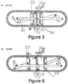
- a DPCE cylinder includes: a compression cylinder 01, a power cylinder 02, a compression piston 03, a power piston 04, two respective piston connecting rods 05 and 06, a compression crankshaft 07, a power crankshaft 08, a crankshaft connecting rod 09, an intake valve 10, an exhaust valve 11 and an interstage valve 12.
- the compression cylinder 01 is a piston engine cylinder that houses the compression piston 03, the intake valve 10 and part of the interstage valve 12.
- the power cylinder 02 is a piston engine cylinder that houses the power piston 04, the exhaust valve 11, part of the interstage valve 12 and a spark plug (not shown) located in front of the surface of power piston 04 facing the combustion chamber in cylinder 02.
- the compression piston 03 serves the intake and the compression engine strokes.
- the power piston 04 serves the power and the exhaust strokes.
- the connecting rods 05 and 06 connect their respective pistons to their respective crankshafts.
- the compression crankshaft 07 converts rotational movements into compression piston 03 reciprocating movement.
- the reciprocating movement of the power piston 04 is converted into rotational movement of the power crankshaft 08, which is in turn converted to engine rotational movement or work (i.e., crankshaft 08- serves as the DPCE output shaft).
- crankshaft connecting rod 09 translates the rotation of power crankshaft 08 into rotation of the compression crankshaft 07.
- the intake valve 10 is composed of a shaft having a conic shaped sealing surface, the same as is used for intake valves in most conventional four stroke engines.
- the exhaust valve 11 is composed of a shaft having a conic shaped sealing surface, the same as is used for exhaust valves in most conventional four stroke engines.
- the interstage valve 12 is also composed of a shaft having a conic shaped sealing surface.
- a compression piston 03. moves relative to the compression cylinder 01 in the direction as indicated by the illustrated arrows.
- the power piston 04 moves relative to the power cylinder 02 in the direction as indicated by the illustrated arrows.
- the compression cylinder 01 and the compression piston 03 define chamber B.
- the power cylinder 02 and the power piston 04 define chamber C.
- the power piston pressure surface has a shaped hollow cavity 26 (see also Fig. 12 ) that supplements chamber C and functions as an additional combustion chamber volume during combustion.
- Chamber B through an interstage mechanical operated valve 12 is in fluid communication with chamber C.
- Compression cylinder 01 has an intake valve 10.
- Chamber B through intake valve 10 is in fluid communication with carbureted fuel/air charge A.
- Power cylinder 02 has an exhaust valve 11.
- Chamber C through exhaust valve 11 is in fluid communication with ambient air D.
- exhaust valve 11 allows exhaust gases to exhale.
- the power piston 04 pushes the power connecting rod 06, causing the power crankshaft 08 to rotate clockwise.
- inertial forces (initiated by flywheel mass - not shown) cause the power crankshaft 08 to continue its clockwise rotation, and cause the power connecting rod 06 to move power piston 04, which in turn exhales burnt fuel exhaust through valve 11.
- the power crankshaft 08 rotation through a crankshaft connecting rod 09 articulates the compression crankshaft 07 for synchronous rotation (i.e., both crankshafts rotate at the same speed and dynamic angles).
- both pistons, the power piston 04 and the compression piston 03 pass through their top dead center (TDC) positions and through their bottom dead center (BDC) positions at the same time.
- TDC top dead center
- BDC bottom dead center
- the relative positions of the power piston 04 and the compression piston 03 may be phase-shifted by a desired amount.
- the DPCE dual cylinder apparatus utilizes conventional pressurized cooling and oil lubrication methods and systems (not shown).
- the power chamber C structure components (such as the cylinder 02 and piston 04) maintain a much higher temperature than conventional combustion engines
- the components of the power chamber C are temperature controlled using a cooling system.
- some or all of the components may be fabricated out of high-temperature resistant materials such as ceramics, carbon, or stainless steel.
- the DPCE apparatus can utilize well-known high voltage timing and spark plug electrical systems (not shown) as well as an electrical starter motor to control spark plug ignitions, timing, and engine initial rotation.
- both crankshafts 07 and 08 start their clockwise rotation and both pistons 03 and 04 begin their reciprocating motion.
- the compression piston 03 and the power piston 04 move in the direction that increases chamber B and chamber C volume. Since intake valve 10 is in its open position and because at this stage chamber B volume constantly increases, carbureted fuel or fresh air charge (when using a fuel injection system) flows from point A (which represents carburetor output port, for example) through intake valve 10 into chamber B.
- point A which represents carburetor output port, for example
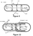
- compression piston 03 reaches its BDC point, intake valve 10 closes trapping chamber B air - fuel charge content. While crankshafts clockwise rotation goes on, and as shown in Fig 9 and Fig 1 through 3 respectively, chamber B volume decreases and its now trapped air - fuel charge temperature and pressure increases. As the compression piston 03 approaches a predetermined point ( Fig 3 ), interstage valve 12 opens and chamber B air - fuel charge flows into chamber C. As the compression piston approaches its TDC point (according to some embodiments some delay or advance may be introduced), the interstage valve 12 simultaneously closes and a spark plug firing occurs.
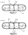
- Figures 5 through 8 illustrate the power stroke.
- chamber C pressure increases forcefully pushing power piston 04 which in turn moves connecting rod 06 to rotate power crankshaft 08, which is coupled to a DPCE output shaft 06'.
- intake valve 10 reopens allowing a new air fuel charge A to be sucked into chamber B.
- the exhaust stroke begins when power piston 04 reaches its BDC point ( Fig. 8 ).
- the exhaust valve 11 opens and as chamber C volume decreases the burned exhaust gases are pushed out from chamber C through open exhaust valve 11 into the ambient environment D.
- the DPCE engine divides the strokes performed by a single piston and cylinder of convention combustion engines into two thermally differentiated cylinders in which each cylinder executes half of the four-stroke cycle.
- a "cold" cylinder executes the intake and compression strokes and a thermally isolated "hot” cylinder executes the combustion and exhaust strokes.
- this innovative system and process enables the DPCE engine to work at higher combustion chamber temperatures and at lower intake and compression chamber temperatures. Utilizing higher combustion temperatures while maintaining lower intake and compression temperatures reduces engine cooling requirements, lowers compression energy requirements and thus boosts engine efficiency. Additionally, thermally isolating the power cylinder from the external environment limits external heat losses, allows the reuse of the same heat energy in the next stroke, and burns less fuel in each cycle.
- the compression cylinder 01 is similar to a conventional piston engine cylinder that houses the compression piston 03, the intake valve 10, and part of the interstage valve 12.
- the compression cylinder 01 works in conjunction with the compression piston 03 to suck and compress incoming air and/or fuel charge.
- the compression cylinder is cooled.
- Figure 10 shows an air cooled compression cylinder having heat absorbing and radiating ribs 20.
- Figure 11 shows a liquid cooled compression cylinder having liquid coolant passages 22.
- the cooling air source or the liquid coolant sources can be the same as well known in the previous art.
- the compression cylinder 01 and the power cylinder 02 should be thermally isolated from each other, as well as the surrounding environment.
- Figure 26 illustrates an embodiment in which the two cylinders are constructed in dissimilar planes, and thus, exercise minimum reciprocal conductivity between the cylinders.
- the power cylinder 02 is a piston engine cylinder that houses the power piston 02, the exhaust valve 11, part of the interstage valve 12, and a spark plug (not shown).
- the power cylinder 02 functions in conjunction with the power piston 04 to combust a compressed air/fuel mixture within a chamber of the cylinder 02 and transfer the resulting energy as mechanical work to the power crankshaft 08.
- the power piston 04 works to exhale or push the exhaust gases out from the cylinder 02 via the exhaust valve 11.
- the power cylinder 02 accommodates a spark-plug located in front of the surface of power piston 04 facing the combustion chamber in cylinder 02.
- the power piston 04 has a shaped hollow cavity 26, which serves as a combustion chamber.
- the power piston 04 pushes the burned gases out of the cylinder 02 via exhaust valve 11.
- the power cylinder 02 is exhaust heated, in addition to being externally thermally isolated.
- Figures 10 and 11 illustrate exhaust heat utilization as exhaust gases, during their exhale stream, conduct heat into power cylinder heating passages 24.
- the compression connecting rod 05 connects the compression crankshaft 07 with the compression piston 03 causing the piston 03 to move relative to the cylinder in a reciprocating motion.
- the power connecting rod 06 connects the power crankshaft 08 with the power piston 04.
- the power connecting rod 06 transfers the piston 04 movement into the power crankshaft 08 causing it to rotate.
- the power crankshaft 08 rotation and momentum pushes the power piston 04 back toward the compression cylinder 01, which causes the burned gases to be exhaled via the exhaust valve (exhaust stroke).
- the compression crankshaft 07 converts rotational movement into compression piston 03 reciprocating movement.
- the compression crankshaft 07 connects the compression connecting rod 05 ( Fig. 1 ) with the crankshaft connecting rod 09. Movement of the crankshaft connecting rod 09 causes the compression crankshaft 07 to rotate.
- Compression crankshaft 07 rotations produce movement of the compression connecting rod 05 that in turn moves the compression piston 03 relative to its cylinder housing 01 in a reciprocating motion.
- the compression crankshaft 07 and power crankshaft 08 structural configuration may vary in accordance with desired engine configurations and designs.
- some crankshaft design factors are: number of dual cylinders, relative cylinder positioning, crankshaft gearing mechanism, and direction of rotation.
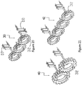
- the axes of the crankshafts 07 and 08 should be positioned 180 degrees from each other, as illustrated in Figure 13 .
- both crankshaft axes should be positioned in phase with respect to one another, as shown in Figure 14 .
- the power crankshaft 08 connects the power connecting rod 06 with the crankshaft connecting rod 09.
- the power piston 04 movement through its power connecting rod 06, causes the power crankshaft 08, which is also coupled to the engine output shaft (not shown), to rotate, which causes the connecting rod 09 to rotate the compression crankshaft 07 and generate reciprocal movement of the compression piston 03.
- crankshaft connecting rod 09 connects the power crankshaft 08 with the compression crankshaft 07 and thus provides both crankshafts with synchronous rotation.
- Figure 15 illustrates a perspective view of the crankshaft connecting rod 09 coupled to respective crankshafts 07 and 08, in accordance with one embodiment of the invention.
- the function of the crankshaft connecting rod 09 is to link the power crankshaft 08 and the compression crankshaft 07.
- both crankshafts 07 and 08 may rotate synchronously and respectively relative to each other (same direction, same angle). In other designs the two crankshafts 07 and 08 may rotate in opposite directions with or without a predetermined phase angle.
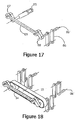
- Figure 17 illustrates perspective view of the connecting rod 09 coupled to respective crankshafts 07 and 08, which are in turn coupled to respective piston connecting rods 05 and 06, wherein the crankshafts 07 and 08 are oriented with respect to each other so as to provide a predetermined phase difference between the otherwise synchronous motion of the pistons 03 and 04.
- a predetermined phase difference means that in order to achieve a time difference between the compression piston TDC position, as illustrated in Figure 4 , and the power piston TDC position, a relative piston phase delay or advance can be introduced into either piston.
- Figure 17 illustrates that the piston connecting rods 05 and 06 are out of phase with respect to each other so as to provide a desired phase delay or advance between the times the pistons 03 and 04 reach their respective TDC positions.
- a phase delay is introduced such that the piston of the power cylinder moves slightly in advance of the piston of the compression cylinder, permitting the compressed charge to be delivered under nearly the full compression stroke and allowing the power piston to complete a full exhaust stroke.
- phase delays with the power piston leading the compression piston are also described in U.S. Pat. No. 1,372,216 to Casaday and U.S. Pat. Application No. 2003/0015171 A1 to Scuderi .
- an opposite phase delay is introduced such that the compression piston moves in advance of the power piston, wherein the power piston further compresses the charge from the compression cylinder before firing. The benefits of this approach are discussed in U.S. Pat. No. 3,880,126 to Thurston et al. and U.S. Pat. No. 3,959,974 to Thomas .
- a second crankshaft connecting rod 13 is utilized as shown in Figure 16 .
- crankshaft connecting rod 14 may be implemented by having one crankshaft connecting rod 14 combined with a timing belt or a chain mechanism 15.
- a chain mechanism or a timing belt mechanism 15 may by itself serve as an alternative to any of the above-mentioned crankshaft connecting mechanisms.
- Figures 20 and 21 illustrate alternative mechanisms to replace the crankshaft connecting rod 09.
- Figure 20 illustrates crankshafts connecting gearwheels mechanism 30, comprising three gearwheels 32 engaged to each other. In this embodiment, both crankshafts 07 and 08 rotate in a unilateral direction (utilizing 3 gearwheels).
- Figure 21 shows two embodiments of a crankshaft connecting gearwheels mechanisms 40 and 42 having an even number of gearwheels 32, thereby configured to turn crankshafts 07 and 08 in opposite directions.
- the intake valve 10 is composed of a shaft having a conic shaped sealing surface, the same as is used as intake valves in most four stroke engines.
- the intake valve 10 governs the ambient air or the carbureted air/fuel charge as they flow into the compression cylinder 01.
- the compression cylinder 01 has at least one intake valve.
- the intake valve location, function, timing and operation may be similar or identical to the intake valves of conventional four strokes internal combustion engines.
- the exhaust valve 11 is composed of a shaft having a conic shaped sealing surface, the same as is used in exhaust valves in most four stroke engines.
- the exhaust valve 11, located on the power cylinder 02 governs burned gaseous exhale flow.
- the power cylinder 02 has at least one exhaust valve.
- the exhaust valve location, functions, timing and operation method may be similar or identical to exhaust valves found in well-known conventional four stroke combustion engines.
- the interstage valve 12 is composed of a shaft having a conic shaped sealing surface.
- the interstage valve governs the compressed air flow or the compressed carbureted air/fuel charge (collectively referred to herein as "fuel” or “fuel mixture”) flow from a volume B within the compression cylinder 01 as it is pushed into a volume C within the power cylinder 02.
- the interstage valve 12 also prevents any reverse flow of fuel from volume C back into volume B.
- the interstage valve 12 When in an open position, the interstage valve 12 enables compressed fuel to flow from the compression cylinder 01 into the power cylinder 02. During combustion and along the power stroke, the interstage valve 12 remains closed.
- the interstage valve operation mechanism may be similar or identical to well-known combustion engine inlet or exhaust valve mechanisms.
- the closed or opened position of the interstage valve 12 is operated by mechanical linkages coupling or engagement with one of the dynamic DPCE shafts/parts (e.g., piston 03).
- one of the dynamic DPCE shafts/parts e.g., piston 03.
- the exact valve timing depends on many engineering design considerations; however, as a general rule the interstage valve 12 should open around the time the exhaust valve 11 closes and remain closed during the power stroke and at least most of the exhaust stroke.
- a preloaded spring-operated relief valve 17 serves as the interstage valve 12.
- This embodiment provides an automatic valve that does not require any linkage based operating mechanism.
- the working pressure and the preloaded spring 16 forces the valve stem 17 to remain closed and sealed.
- the increased compressed fuel pressure in volume B along with the decreased exhaust pressure in volume C overcome the valve preloaded spring 16 forces and thus opens the valve stem 17, thereby allowing the compressed fuel to flow into the power cylinder 02 chamber C.
- Figure 24 illustrates a combination of a combustion chamber E with a unique semi automatic interstage valve comprising valve 18 having a cylindrical or ring portion that surrounds a plug valve 19.
- a combustion chamber E is sealed from the compression chamber B by the valve 18 and sealed from the working chamber C by valve 19.
- a spring 20 pushes simultaneity both valves 18 and 19 toward their corresponded closed positions.
- a spark plug 21 is located inside the combustion chamber E cavity.
- the combustion chamber E and interstage valve operation is as follows: As illustrated at stage J, during initial compression and exhaust strokes, spring 20 pushes valve stem 18 and valve stem 19 causing both valves to stay in a sealed closed position.
- valve 19 stays open because of the differential pressure which exists between chamber C high combustion pressure vis-à-vis the much lower pressure that resides in chamber B which is now in its intake phase.
- the combustion chamber and interstage valve cycle ends as the power stroke ends.
- Spring 20 then pushes back valve 19 to its closed position as the power piston 22 begins its exhaust stroke.
- Figure 25 illustrates a DPCE dual cylinder configuration having supercharge capabilities, in accordance with one embodiment of the invention.
- the compression cylinder portion 50 is larger than the power cylinder portion 52, therefore allowing a greater volume of air/fuel mixture to be received and compressed in the compression chamber B.
- the larger volume and increased pressure of compressed air/fuel mixture (i.e., "supercharged" fuel mixture) in the compression chamber B is injected into the combustion chamber C via interstage valve 12. Therefore, a greater amount and/or higher pressure of fuel mixture can be injected into the combustion chamber C of power cylinder 52 to provide a bigger explosion and, hence, more energy and work, during the power stroke.
- Figure 26 illustrates an alternative DPCE dual cylinder configuration, in accordance with one embodiment of the invention, wherein the compression cylinder 60 is offset from the power cylinder 62, to provide minimal thermal conductivity between the two cylinders.
- the interstage valve 12 is located in the small area of overlap between the two cylinders.
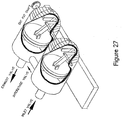
- Figure 27 illustrates a DPCE dual cylinder configuration in which both cylinders are constructed parallel to each other and both pistons are moving in a tandem manner, in accordance with a further embodiment of the invention.
- the intake, exhaust, and interstage valves may operate in the same manner as described above.
- the interstage valve is located in a lateral conduit that couples the first and second cylinders.
Claims (17)
- Doppelkolbenvorrichtung zur Verwendung in einem Verbrennungsmotor, umfassend: einen ersten Zylinder (1), in dem ein erster Kolben (3) untergebracht ist;
einen zweiten Zylinder (2), in dem ein zweiter Kolben (4) untergebracht ist, wobei sich der erste und der zweite Zylinder nebeneinander befinden, so dass wenigstens ein Abschnitt einer Oberfläche des ersten Zylinders wenigstens neben einem Abschnitt einer Oberfläche des zweiten Zylinders angeordnet und mit diesem fließend gekoppelt ist, wobei der Abschnitt des ersten Zylinders neben dem Abschnitt des zweiten Zylinders angeordnet ist;
ein Einlassventil (1), das mit dem ersten Zylinder gekoppelt ist, um zu ermöglichen, dass ein Kraftstoffgemisch in den ersten Zylinder eintreten kann, wobei der erste Kolben nur Einlass- und Kompressionshübe ausführt;
ein Auslassventil (11), das an einem Kopf des zweiten Zylinders positioniert und mit dem zweiten Zylinder gekoppelt ist, um zu ermöglichen, dass ein Abgas aus dem zweiten Zylinder austreten kann, wobei der zweite Kolben nur Verbrennungs- und Auslasshübe ausführt; und
ein Zwischenstufenventil (12), das sich nahe zu neben ihm angeordneten Oberflächenabschnitten des ersten und des zweiten Zylinders befindet, um eine innere Kammer des ersten Zylinders mit einer inneren Kammer des zweiten Zylinders in Fluidverbindung zu bringen;
dadurch gekennzeichnet, dass sich der erste und der zweite Zylinder parallel und in Tandem zueinander befinden, so dass wenigstens ein Abschnitt einer oberen Oberfläche des ersten Zylinders neben wenigstens einem Abschnitt einer oberen Oberfläche des zweiten Zylinders angeordnet ist und mit diesem fließend gekoppelt ist, um den Totraum zwischen dem ersten und dem zweiten Zylinder zu minimieren. - Vorrichtung nach Anspruch 1, ferner umfassend:eine erste Kurbelwelle (7), die mit dem ersten Kolben (3) gekoppelt ist;eine zweite Kurbelwelle (8), die mit dem zweiten Kolben (4) gekoppelt ist; undeinen Kurbelwellenverbindungsmechanismus (9, 13, 14, 40, 42), der mit der ersten und zweiten Kurbelwelle gekoppelt ist und konfiguriert ist, um die Bewegung zwischen der ersten und der zweiten Kurbelwelle zu übertragen.
- Vorrichtung nach Anspruch 2, wobei der Kurbelwellenverbindungsmechanismus eine Kurbelwellenverbindungsstange (9, 13, 14, 40, 42) umfasst, deren erstes und zweites Ende mit der ersten bzw. zweiten Kurbelwelle (7,8) gekoppelt sind.
- Vorrichtung nach Anspruch 2, wobei der Kurbelwellenverbindungsmechanismus (9, 13, 14, 40, 42) mehrere Zahnräder (32) umfasst, wobei ein erstes Zahnrad (32) mit der ersten Kurbelwelle (7) gekoppelt ist, ein zweites Zahnrad (32) mit der zweiten Kurbelwelle (8) gekoppelt ist, und das erste und das zweite Zahnrad mechanisch miteinander gekoppelt sind.
- Vorrichtung nach Anspruch 2, wobei der Kurbelwellenverbindungsmechanismus (9, 13, 14, 40, 42) einen Antriebsriemen oder eine Antriebskette (15) umfasst, die mit der ersten und zweiten Kurbelwelle (7, 8) gekoppelt ist.
- Vorrichtung nach Anspruch 1, wobei sich der erste und der zweite Kolben (3, 4) in ihren jeweiligen ersten und zweiten Zylindern (1, 2) gleichzeitig phasengleich zueinander bewegen.
- Vorrichtung nach Anspruch 1, wobei sich der erste und der zweite Kolben (3, 4) in ihren jeweiligen ersten und zweiten Zylindern (1, 2) gleichzeitig phasenverschoben zueinander bewegen.
- Vorrichtung nach Anspruch 7, wobei sich der zweite Kolben (4) leicht phasenverschoben vor dem ersten Kolben (3) bewegt.
- Vorrichtung nach Anspruch 7, wobei sich der erste Kolben (3) leicht phasenverschoben vor dem zweiten Kolben (4) bewegt.
- Vorrichtung nach Anspruch 1, wobei ein Innenvolumen des ersten Zylinders (1) größer ist als ein Innenvolumen des zweiten Zylinders (2).
- Vorrichtung nach Anspruch 1, wobei der zweite Kolben (3) eine darin ausgebildete Kammer (26) umfasst, die als Brennkammer fungiert.
- Vorrichtung nach Anspruch 1, wobei der erste und der zweite Zylinder (1, 2) thermisch voneinander isoliert sind.
- Vorrichtung nach Anspruch 1, wobei der erste und der zweite Zylinder (1, 2) räumlich voneinander versetzt sind und sich das Zwischenstufenventil (12) in einem Bereich räumlicher Überlappung zwischen dem ersten und dem zweiten Zylinder befindet.
- Vorrichtung nach Anspruch 1, wobei der erste und der zweite Zylinder (1, 2) positioniert sind, um eine V-Konfiguration zu bilden, und sich das Zwischenstufenventil (12) in einem Bereich räumlicher Überlappung zwischen dem ersten und dem zweiten Zylinder befindet.
- Vorrichtung nach Anspruch 1, wobei das Zwischenstufenventil (12) federbelastet ist.
- Vorrichtung nach Anspruch 1, wobei der erste und der zweite Zylinder (1, 2) thermisch voneinander isoliert sind.
- Vorrichtung nach Anspruch 1, wobei das Zwischenstufenventil (12) ein halbautomatisches Federventil umfasst, umfassend:ein erstes Ventil (18) mit einer konisch geformten Dichtfläche und einer zylindrischen Welle;ein zweites Ventil (19) mit einer kegelförmigen Dichtfläche und einer massiven stabförmigen Welle, wobei die zylindrische Welle die massive stabförmige Welle umgibt; undeine Feder (20), die die zylindrische Welle umgibt und konfiguriert ist, um gleichzeitig das erste und das zweite Ventil in ihre entsprechenden geschlossenen Positionen zu drücken.
Applications Claiming Priority (2)
| Application Number | Priority Date | Filing Date | Title |
|---|---|---|---|
| US66119505P | 2005-03-11 | 2005-03-11 | |
| PCT/US2006/008526 WO2006099106A2 (en) | 2005-03-11 | 2006-03-09 | Double piston cycle engine |
Publications (3)
| Publication Number | Publication Date |
|---|---|
| EP1866530A2 EP1866530A2 (de) | 2007-12-19 |
| EP1866530A4 EP1866530A4 (de) | 2013-04-03 |
| EP1866530B1 true EP1866530B1 (de) | 2020-07-29 |
Family
ID=36992252
Family Applications (1)
| Application Number | Title | Priority Date | Filing Date |
|---|---|---|---|
| EP06737682.2A Active EP1866530B1 (de) | 2005-03-11 | 2006-03-09 | Doppelkolbenzyklusmotor |
Country Status (7)
| Country | Link |
|---|---|
| US (2) | US7383797B2 (de) |
| EP (1) | EP1866530B1 (de) |
| JP (2) | JP2008533362A (de) |
| KR (1) | KR101321558B1 (de) |
| CN (1) | CN101548082B (de) |
| RU (1) | RU2007137638A (de) |
| WO (1) | WO2006099106A2 (de) |
Families Citing this family (23)
| Publication number | Priority date | Publication date | Assignee | Title |
|---|---|---|---|---|
| US8905801B1 (en) | 2007-12-31 | 2014-12-09 | Brp Us Inc. | Marine outboard motor |
| US8584629B2 (en) * | 2009-01-24 | 2013-11-19 | Tour Engine, Inc. | Interstage valve in double piston cycle engine |
| WO2012051645A1 (en) * | 2010-10-19 | 2012-04-26 | Jbec Pty Limited | Method and means for controlling combustion |
| CN102852639A (zh) * | 2011-08-19 | 2013-01-02 | 摩尔动力(北京)技术股份有限公司 | 对置活塞发动机 |
| CN104302886B (zh) * | 2011-11-30 | 2018-06-05 | 托尔发动机股份有限公司 | 双活塞循环引擎中的交换阀 |
| EP2850301B1 (de) * | 2012-05-18 | 2016-10-12 | Raymond F. Lippitt | Verbrennungsmotoren |
| US8443769B1 (en) | 2012-05-18 | 2013-05-21 | Raymond F. Lippitt | Internal combustion engines |
| US8893671B2 (en) | 2012-08-22 | 2014-11-25 | Jack R. Taylor | Full expansion internal combustion engine with co-annular pistons |
| US9303559B2 (en) | 2012-10-16 | 2016-04-05 | Raymond F. Lippitt | Internal combustion engines |
| HUE042205T2 (hu) | 2013-07-17 | 2019-06-28 | Tour Engine Inc | Orsó ingázó keresztszelep osztott ciklusú motorban |
| US9719444B2 (en) | 2013-11-05 | 2017-08-01 | Raymond F. Lippitt | Engine with central gear train |
| US9664044B2 (en) | 2013-11-15 | 2017-05-30 | Raymond F. Lippitt | Inverted V-8 I-C engine and method of operating same in a vehicle |
| US9217365B2 (en) | 2013-11-15 | 2015-12-22 | Raymond F. Lippitt | Inverted V-8 internal combustion engine and method of operating the same modes |
| WO2016116928A1 (en) | 2015-01-19 | 2016-07-28 | Tour Engine, Inc. | Split cycle engine with crossover shuttle valve |
| FR3033834A1 (fr) * | 2015-03-20 | 2016-09-23 | Cladel Alexandre Bernard Henri | Moteur thermique a chambre de compression/explosion separe |
| CN104963760B (zh) * | 2015-08-03 | 2017-07-28 | 湖州新奥利吸附材料有限公司 | 一种分体式内燃机的控制系统 |
| CN104963759B (zh) * | 2015-08-03 | 2018-04-13 | 湖州新奥利吸附材料有限公司 | 一种具有进气排气控制装置的分体式内燃机压缩缸 |
| US10260598B2 (en) | 2016-04-29 | 2019-04-16 | Achates Power, Inc. | Transmissions for opposed-piston engines with two crankshafts |
| ES2697623B2 (es) * | 2017-11-09 | 2019-11-06 | Lostao Luis Carrillo | Motor de combustion interna con pistones opuestos y eje de potencia central |
| ES2923588T3 (es) * | 2018-07-11 | 2022-09-28 | Hypertec Solution S R L | Motor de combustión interna de dos tiempos y método de accionamiento relativo |
| KR20210109527A (ko) | 2018-11-09 | 2021-09-06 | 투어 엔진 인코퍼레이티드 | 스플릿-사이클 엔진의 전달 메커니즘 |
| CN113389639B (zh) * | 2020-03-12 | 2022-09-27 | 赵天安 | 一种带压缩比调节机构的发动机 |
| CN114776444A (zh) * | 2022-04-24 | 2022-07-22 | 门立山 | 一种高效率内燃机 |
Family Cites Families (53)
| Publication number | Priority date | Publication date | Assignee | Title |
|---|---|---|---|---|
| US982850A (en) | 1907-02-23 | 1911-01-31 | C P Power Company | Internal-combustion steam-motor. |
| US1139713A (en) | 1913-05-07 | 1915-05-18 | William H Osterman | Internal-combustion engine. |
| US1372216A (en) * | 1919-03-12 | 1921-03-22 | James O Casaday | Internal-combustion engine |
| US1369511A (en) * | 1919-06-09 | 1921-02-22 | Wiesner Henry | Internal-combustion engine |
| US1633921A (en) * | 1922-10-26 | 1927-06-28 | Automotive Valves Co | Internal-combustion engine |
| US1535423A (en) * | 1923-05-28 | 1925-04-28 | Latta Charles | Internal-combustion engine |
| US2169807A (en) * | 1938-03-04 | 1939-08-15 | George R Lyon | Compressor |
| US3069915A (en) * | 1958-08-04 | 1962-12-25 | Jr William S Sawle | Coupling assembly for engine crankshafts |
| US3143282A (en) * | 1962-06-18 | 1964-08-04 | Battelle Development Corp | Free-piston engine compressor |
| US3221718A (en) * | 1964-01-09 | 1965-12-07 | Continental Aviat & Eng Corp | Piston construction |
| US3623463A (en) * | 1969-09-24 | 1971-11-30 | Gerrit De Vries | Internal combustion engine |
| US3675630A (en) * | 1970-07-02 | 1972-07-11 | Cleo C Stratton | Engine |
| US3808818A (en) * | 1972-08-04 | 1974-05-07 | Gen Motors Corp | Dual combustion engine and cycle |
| US3805752A (en) * | 1973-02-23 | 1974-04-23 | Gen Motors Corp | Quenched combustion separated charge internal combustion engine |
| US3880126A (en) * | 1973-05-10 | 1975-04-29 | Gen Motors Corp | Split cylinder engine and method of operation |
| US3991721A (en) * | 1974-01-17 | 1976-11-16 | Hurd Fraser A | Low emission compound combustion engine |
| US3959974A (en) | 1974-09-19 | 1976-06-01 | Thomas Luther B | Internal combustion engine |
| US4157080A (en) * | 1975-02-11 | 1979-06-05 | Hill Craig C | Internal combustion engine having compartmented combustion chamber |
| US4040400A (en) * | 1975-09-02 | 1977-08-09 | Karl Kiener | Internal combustion process and engine |
| US4159700A (en) * | 1976-10-18 | 1979-07-03 | Mccrum William H | Internal combustion compound engines |
| US4086882A (en) * | 1976-10-18 | 1978-05-02 | Mccrum William H | Compound combustion engines and methods of compounding same |
| US4202300A (en) * | 1978-02-22 | 1980-05-13 | Frank Skay | Internal combustion engine |
| FR2505930A1 (fr) * | 1981-05-12 | 1982-11-19 | Huguet Francis | Moteur a combustion interne a consommation reduite |
| US4359017A (en) * | 1981-06-12 | 1982-11-16 | May Claude H | Internal combustion engine |
| US4565167A (en) * | 1981-12-08 | 1986-01-21 | Bryant Clyde C | Internal combustion engine |
| US4635590A (en) * | 1983-04-28 | 1987-01-13 | Anthony Gerace | Internal combustion engine and operating cycle therefor |
| DE3634966A1 (de) * | 1985-11-28 | 1987-06-04 | Schulz & Rackow | Fuellarmatur |
| US4787343A (en) * | 1986-11-07 | 1988-11-29 | Walbro Corporation | Combustion enhancer for internal combustion engines |
| BE1002364A4 (fr) * | 1988-12-30 | 1991-01-15 | Schmitz Gerhard | Moteur a combustion interne a deux temps etages. |
| US5265564A (en) * | 1989-06-16 | 1993-11-30 | Dullaway Glen A | Reciprocating piston engine with pumping and power cylinders |
| CN1086584A (zh) * | 1992-11-02 | 1994-05-11 | 张宝旺 | 无噪音内燃机 |
| DE9301007U1 (de) | 1993-01-26 | 1993-03-11 | Brenner, Raimund, 4100 Duisburg, De | |
| US5431130A (en) * | 1993-11-08 | 1995-07-11 | Brackett; Douglas C. | Internal combustion engine with stroke specialized cylinders |
| US5546897A (en) * | 1993-11-08 | 1996-08-20 | Brackett; Douglas C. | Internal combustion engine with stroke specialized cylinders |
| WO1997016634A1 (en) * | 1995-11-01 | 1997-05-09 | Barry Frank Hughes | Combination internal combustion and steam engine |
| US5623894A (en) | 1995-11-14 | 1997-04-29 | Caterpillar Inc. | Dual compression and dual expansion engine |
| US5857436A (en) * | 1997-09-08 | 1999-01-12 | Thermo Power Corporation | Internal combustion engine and method for generating power |
| JPH11343801A (ja) * | 1998-06-02 | 1999-12-14 | Nippon Software Approach:Kk | 往復動ピストン機関及びリンク機構 |
| US6318310B1 (en) * | 1999-08-05 | 2001-11-20 | Caterpillar Inc. | Internal combustion engine |
| EP1214506B1 (de) * | 1999-08-31 | 2005-08-10 | Richard Patton | Brennkraftmaschine mit regenerator und heissluftzündvorrichtung |
| US6606970B2 (en) * | 1999-08-31 | 2003-08-19 | Richard Patton | Adiabatic internal combustion engine with regenerator and hot air ignition |
| US7021272B2 (en) * | 1999-12-17 | 2006-04-04 | Satnarine Singh | Computer controlled multi-stroke cycle power generating assembly and method of operation |
| SE0001313D0 (sv) * | 2000-04-10 | 2000-04-10 | Jerzy Chomiak | Turbocharger utilizing waste heat of an internal combustion engine |
| BE1013791A5 (fr) * | 2000-10-26 | 2002-08-06 | Gerhard Schmitz | Moteur a combustion interne a cinq temps. |
| US6543225B2 (en) * | 2001-07-20 | 2003-04-08 | Scuderi Group Llc | Split four stroke cycle internal combustion engine |
| US6789514B2 (en) * | 2001-07-30 | 2004-09-14 | Massachusetts Institute Of Technology | Internal combustion engine |
| US6880501B2 (en) * | 2001-07-30 | 2005-04-19 | Massachusetts Institute Of Technology | Internal combustion engine |
| WO2003040530A2 (en) * | 2001-11-02 | 2003-05-15 | Scuderi Group Llc | Split four stroke engine |
| JP3881872B2 (ja) * | 2001-11-15 | 2007-02-14 | 本田技研工業株式会社 | 内燃機関 |
| US6796127B2 (en) * | 2002-08-27 | 2004-09-28 | John F. Helm | One cycle internal combustion engine |
| JP3885206B2 (ja) * | 2002-11-11 | 2007-02-21 | 胡 龍潭 | 八行程内燃機関 |
| US6986329B2 (en) * | 2003-07-23 | 2006-01-17 | Scuderi Salvatore C | Split-cycle engine with dwell piston motion |
| US6994057B2 (en) * | 2004-03-04 | 2006-02-07 | Loth John L | Compression ignition engine by air injection from air-only cylinder to adjacent air-fuel cylinder |
-
2006
- 2006-03-09 EP EP06737682.2A patent/EP1866530B1/de active Active
- 2006-03-09 RU RU2007137638/06A patent/RU2007137638A/ru unknown
- 2006-03-09 US US11/371,827 patent/US7383797B2/en active Active
- 2006-03-09 WO PCT/US2006/008526 patent/WO2006099106A2/en active Application Filing
- 2006-03-09 KR KR1020077023348A patent/KR101321558B1/ko active IP Right Grant
- 2006-03-09 CN CN200680007871XA patent/CN101548082B/zh active Active
- 2006-03-09 JP JP2008500950A patent/JP2008533362A/ja not_active Withdrawn
-
2008
- 2008-02-29 US US12/040,804 patent/US7516723B2/en active Active
-
2012
- 2012-04-13 JP JP2012091757A patent/JP5514247B2/ja active Active
Non-Patent Citations (1)
| Title |
|---|
| None * |
Also Published As
| Publication number | Publication date |
|---|---|
| EP1866530A2 (de) | 2007-12-19 |
| JP5514247B2 (ja) | 2014-06-04 |
| US20080141956A1 (en) | 2008-06-19 |
| EP1866530A4 (de) | 2013-04-03 |
| WO2006099106A3 (en) | 2009-04-02 |
| US20060243228A1 (en) | 2006-11-02 |
| RU2007137638A (ru) | 2009-04-20 |
| KR20080011162A (ko) | 2008-01-31 |
| JP2012180835A (ja) | 2012-09-20 |
| CN101548082A (zh) | 2009-09-30 |
| WO2006099106A2 (en) | 2006-09-21 |
| CN101548082B (zh) | 2013-01-23 |
| KR101321558B1 (ko) | 2013-10-22 |
| US7516723B2 (en) | 2009-04-14 |
| US7383797B2 (en) | 2008-06-10 |
| JP2008533362A (ja) | 2008-08-21 |
Similar Documents
| Publication | Publication Date | Title |
|---|---|---|
| EP1866530B1 (de) | Doppelkolbenzyklusmotor | |
| US7273023B2 (en) | Steam enhanced double piston cycle engine | |
| US11230965B2 (en) | Spool shuttle crossover valve and combustion chamber in split-cycle engine | |
| US7942116B2 (en) | Double action piston assembly | |
| JP3016485B2 (ja) | クランク無し往復運動2サイクル内燃機関 | |
| US8033265B2 (en) | Rotary piston internal combustion engine | |
| US8584629B2 (en) | Interstage valve in double piston cycle engine | |
| EP2805016B1 (de) | Verbrennungsmotoren | |
| AU766571B2 (en) | Z-engine | |
| EP1875055A2 (de) | Doppelkolben-taktmotor mit dampfverstärkung | |
| WO2022105984A1 (en) | An internal combustion engine system |
Legal Events
| Date | Code | Title | Description |
|---|---|---|---|
| PUAI | Public reference made under article 153(3) epc to a published international application that has entered the european phase |
Free format text: ORIGINAL CODE: 0009012 |
|
| 17P | Request for examination filed |
Effective date: 20071004 |
|
| AK | Designated contracting states |
Kind code of ref document: A2 Designated state(s): AT BE BG CH CY CZ DE DK EE ES FI FR GB GR HU IE IS IT LI LT LU LV MC NL PL PT RO SE SI SK TR |
|
| AX | Request for extension of the european patent |
Extension state: AL BA HR MK YU |
|
| DAX | Request for extension of the european patent (deleted) | ||
| R17D | Deferred search report published (corrected) |
Effective date: 20090402 |
|
| A4 | Supplementary search report drawn up and despatched |
Effective date: 20130228 |
|
| RIC1 | Information provided on ipc code assigned before grant |
Ipc: F02B 25/08 20060101AFI20130222BHEP Ipc: F02B 75/28 20060101ALI20130222BHEP |
|
| STAA | Information on the status of an ep patent application or granted ep patent |
Free format text: STATUS: EXAMINATION IS IN PROGRESS |
|
| 17Q | First examination report despatched |
Effective date: 20170608 |
|
| GRAP | Despatch of communication of intention to grant a patent |
Free format text: ORIGINAL CODE: EPIDOSNIGR1 |
|
| STAA | Information on the status of an ep patent application or granted ep patent |
Free format text: STATUS: GRANT OF PATENT IS INTENDED |
|
| INTG | Intention to grant announced |
Effective date: 20200221 |
|
| GRAS | Grant fee paid |
Free format text: ORIGINAL CODE: EPIDOSNIGR3 |
|
| GRAA | (expected) grant |
Free format text: ORIGINAL CODE: 0009210 |
|
| STAA | Information on the status of an ep patent application or granted ep patent |
Free format text: STATUS: THE PATENT HAS BEEN GRANTED |
|
| REG | Reference to a national code |
Ref country code: DE Ref legal event code: R081 Ref document number: 602006059573 Country of ref document: DE Owner name: TOUR ENGINE, INC., SAN DIEGO, US Free format text: FORMER OWNER: TOUR ENGINE, INC., SAN DIEGO, CALIF., US |
|
| AK | Designated contracting states |
Kind code of ref document: B1 Designated state(s): AT BE BG CH CY CZ DE DK EE ES FI FR GB GR HU IE IS IT LI LT LU LV MC NL PL PT RO SE SI SK TR |
|
| REG | Reference to a national code |
Ref country code: GB Ref legal event code: FG4D |
|
| REG | Reference to a national code |
Ref country code: CH Ref legal event code: EP |
|
| REG | Reference to a national code |
Ref country code: DE Ref legal event code: R096 Ref document number: 602006059573 Country of ref document: DE |
|
| REG | Reference to a national code |
Ref country code: AT Ref legal event code: REF Ref document number: 1296068 Country of ref document: AT Kind code of ref document: T Effective date: 20200815 |
|
| REG | Reference to a national code |
Ref country code: IE Ref legal event code: FG4D |
|
| REG | Reference to a national code |
Ref country code: LT Ref legal event code: MG4D |
|
| REG | Reference to a national code |
Ref country code: NL Ref legal event code: MP Effective date: 20200729 |
|
| REG | Reference to a national code |
Ref country code: AT Ref legal event code: MK05 Ref document number: 1296068 Country of ref document: AT Kind code of ref document: T Effective date: 20200729 |
|
| PG25 | Lapsed in a contracting state [announced via postgrant information from national office to epo] |
Ref country code: BG Free format text: LAPSE BECAUSE OF FAILURE TO SUBMIT A TRANSLATION OF THE DESCRIPTION OR TO PAY THE FEE WITHIN THE PRESCRIBED TIME-LIMIT Effective date: 20201029 Ref country code: LT Free format text: LAPSE BECAUSE OF FAILURE TO SUBMIT A TRANSLATION OF THE DESCRIPTION OR TO PAY THE FEE WITHIN THE PRESCRIBED TIME-LIMIT Effective date: 20200729 Ref country code: ES Free format text: LAPSE BECAUSE OF FAILURE TO SUBMIT A TRANSLATION OF THE DESCRIPTION OR TO PAY THE FEE WITHIN THE PRESCRIBED TIME-LIMIT Effective date: 20200729 Ref country code: GR Free format text: LAPSE BECAUSE OF FAILURE TO SUBMIT A TRANSLATION OF THE DESCRIPTION OR TO PAY THE FEE WITHIN THE PRESCRIBED TIME-LIMIT Effective date: 20201030 Ref country code: FI Free format text: LAPSE BECAUSE OF FAILURE TO SUBMIT A TRANSLATION OF THE DESCRIPTION OR TO PAY THE FEE WITHIN THE PRESCRIBED TIME-LIMIT Effective date: 20200729 Ref country code: PT Free format text: LAPSE BECAUSE OF FAILURE TO SUBMIT A TRANSLATION OF THE DESCRIPTION OR TO PAY THE FEE WITHIN THE PRESCRIBED TIME-LIMIT Effective date: 20201130 Ref country code: SE Free format text: LAPSE BECAUSE OF FAILURE TO SUBMIT A TRANSLATION OF THE DESCRIPTION OR TO PAY THE FEE WITHIN THE PRESCRIBED TIME-LIMIT Effective date: 20200729 Ref country code: AT Free format text: LAPSE BECAUSE OF FAILURE TO SUBMIT A TRANSLATION OF THE DESCRIPTION OR TO PAY THE FEE WITHIN THE PRESCRIBED TIME-LIMIT Effective date: 20200729 |
|
| PG25 | Lapsed in a contracting state [announced via postgrant information from national office to epo] |
Ref country code: PL Free format text: LAPSE BECAUSE OF FAILURE TO SUBMIT A TRANSLATION OF THE DESCRIPTION OR TO PAY THE FEE WITHIN THE PRESCRIBED TIME-LIMIT Effective date: 20200729 Ref country code: LV Free format text: LAPSE BECAUSE OF FAILURE TO SUBMIT A TRANSLATION OF THE DESCRIPTION OR TO PAY THE FEE WITHIN THE PRESCRIBED TIME-LIMIT Effective date: 20200729 Ref country code: IS Free format text: LAPSE BECAUSE OF FAILURE TO SUBMIT A TRANSLATION OF THE DESCRIPTION OR TO PAY THE FEE WITHIN THE PRESCRIBED TIME-LIMIT Effective date: 20201129 |
|
| PG25 | Lapsed in a contracting state [announced via postgrant information from national office to epo] |
Ref country code: NL Free format text: LAPSE BECAUSE OF FAILURE TO SUBMIT A TRANSLATION OF THE DESCRIPTION OR TO PAY THE FEE WITHIN THE PRESCRIBED TIME-LIMIT Effective date: 20200729 |
|
| PG25 | Lapsed in a contracting state [announced via postgrant information from national office to epo] |
Ref country code: RO Free format text: LAPSE BECAUSE OF FAILURE TO SUBMIT A TRANSLATION OF THE DESCRIPTION OR TO PAY THE FEE WITHIN THE PRESCRIBED TIME-LIMIT Effective date: 20200729 Ref country code: DK Free format text: LAPSE BECAUSE OF FAILURE TO SUBMIT A TRANSLATION OF THE DESCRIPTION OR TO PAY THE FEE WITHIN THE PRESCRIBED TIME-LIMIT Effective date: 20200729 Ref country code: CZ Free format text: LAPSE BECAUSE OF FAILURE TO SUBMIT A TRANSLATION OF THE DESCRIPTION OR TO PAY THE FEE WITHIN THE PRESCRIBED TIME-LIMIT Effective date: 20200729 Ref country code: EE Free format text: LAPSE BECAUSE OF FAILURE TO SUBMIT A TRANSLATION OF THE DESCRIPTION OR TO PAY THE FEE WITHIN THE PRESCRIBED TIME-LIMIT Effective date: 20200729 Ref country code: IT Free format text: LAPSE BECAUSE OF FAILURE TO SUBMIT A TRANSLATION OF THE DESCRIPTION OR TO PAY THE FEE WITHIN THE PRESCRIBED TIME-LIMIT Effective date: 20200729 |
|
| REG | Reference to a national code |
Ref country code: DE Ref legal event code: R097 Ref document number: 602006059573 Country of ref document: DE |
|
| PLBE | No opposition filed within time limit |
Free format text: ORIGINAL CODE: 0009261 |
|
| STAA | Information on the status of an ep patent application or granted ep patent |
Free format text: STATUS: NO OPPOSITION FILED WITHIN TIME LIMIT |
|
| PG25 | Lapsed in a contracting state [announced via postgrant information from national office to epo] |
Ref country code: SK Free format text: LAPSE BECAUSE OF FAILURE TO SUBMIT A TRANSLATION OF THE DESCRIPTION OR TO PAY THE FEE WITHIN THE PRESCRIBED TIME-LIMIT Effective date: 20200729 |
|
| 26N | No opposition filed |
Effective date: 20210430 |
|
| PG25 | Lapsed in a contracting state [announced via postgrant information from national office to epo] |
Ref country code: SI Free format text: LAPSE BECAUSE OF FAILURE TO SUBMIT A TRANSLATION OF THE DESCRIPTION OR TO PAY THE FEE WITHIN THE PRESCRIBED TIME-LIMIT Effective date: 20200729 |
|
| PG25 | Lapsed in a contracting state [announced via postgrant information from national office to epo] |
Ref country code: MC Free format text: LAPSE BECAUSE OF FAILURE TO SUBMIT A TRANSLATION OF THE DESCRIPTION OR TO PAY THE FEE WITHIN THE PRESCRIBED TIME-LIMIT Effective date: 20200729 |
|
| REG | Reference to a national code |
Ref country code: CH Ref legal event code: PL |
|
| REG | Reference to a national code |
Ref country code: BE Ref legal event code: MM Effective date: 20210331 |
|
| PG25 | Lapsed in a contracting state [announced via postgrant information from national office to epo] |
Ref country code: LU Free format text: LAPSE BECAUSE OF NON-PAYMENT OF DUE FEES Effective date: 20210309 Ref country code: LI Free format text: LAPSE BECAUSE OF NON-PAYMENT OF DUE FEES Effective date: 20210331 Ref country code: CH Free format text: LAPSE BECAUSE OF NON-PAYMENT OF DUE FEES Effective date: 20210331 Ref country code: IE Free format text: LAPSE BECAUSE OF NON-PAYMENT OF DUE FEES Effective date: 20210309 |
|
| PG25 | Lapsed in a contracting state [announced via postgrant information from national office to epo] |
Ref country code: BE Free format text: LAPSE BECAUSE OF NON-PAYMENT OF DUE FEES Effective date: 20210331 |
|
| PGFP | Annual fee paid to national office [announced via postgrant information from national office to epo] |
Ref country code: FR Payment date: 20230110 Year of fee payment: 18 |
|
| PG25 | Lapsed in a contracting state [announced via postgrant information from national office to epo] |
Ref country code: HU Free format text: LAPSE BECAUSE OF FAILURE TO SUBMIT A TRANSLATION OF THE DESCRIPTION OR TO PAY THE FEE WITHIN THE PRESCRIBED TIME-LIMIT; INVALID AB INITIO Effective date: 20060309 Ref country code: CY Free format text: LAPSE BECAUSE OF FAILURE TO SUBMIT A TRANSLATION OF THE DESCRIPTION OR TO PAY THE FEE WITHIN THE PRESCRIBED TIME-LIMIT Effective date: 20200729 |
|
| PGFP | Annual fee paid to national office [announced via postgrant information from national office to epo] |
Ref country code: GB Payment date: 20230119 Year of fee payment: 18 Ref country code: DE Payment date: 20230110 Year of fee payment: 18 |