EP1866196B1 - Servodirection electromecanique - Google Patents
Servodirection electromecanique Download PDFInfo
- Publication number
- EP1866196B1 EP1866196B1 EP06723812A EP06723812A EP1866196B1 EP 1866196 B1 EP1866196 B1 EP 1866196B1 EP 06723812 A EP06723812 A EP 06723812A EP 06723812 A EP06723812 A EP 06723812A EP 1866196 B1 EP1866196 B1 EP 1866196B1
- Authority
- EP
- European Patent Office
- Prior art keywords
- motor
- coupling
- shaft
- worm shaft
- worm
- Prior art date
- Legal status (The legal status is an assumption and is not a legal conclusion. Google has not performed a legal analysis and makes no representation as to the accuracy of the status listed.)
- Active
Links
- 230000008878 coupling Effects 0.000 claims abstract description 49
- 238000010168 coupling process Methods 0.000 claims abstract description 49
- 238000005859 coupling reaction Methods 0.000 claims abstract description 49
- 229920001971 elastomer Polymers 0.000 claims description 9
- 239000000806 elastomer Substances 0.000 claims description 8
- 210000000078 claw Anatomy 0.000 claims description 6
- 230000005540 biological transmission Effects 0.000 description 18
- 238000006073 displacement reaction Methods 0.000 description 2
- 238000005259 measurement Methods 0.000 description 2
- 238000000034 method Methods 0.000 description 2
- 230000002411 adverse Effects 0.000 description 1
- 238000004519 manufacturing process Methods 0.000 description 1
- 229910052751 metal Inorganic materials 0.000 description 1
Images


Classifications
-
- B—PERFORMING OPERATIONS; TRANSPORTING
- B62—LAND VEHICLES FOR TRAVELLING OTHERWISE THAN ON RAILS
- B62D—MOTOR VEHICLES; TRAILERS
- B62D5/00—Power-assisted or power-driven steering
- B62D5/04—Power-assisted or power-driven steering electrical, e.g. using an electric servo-motor connected to, or forming part of, the steering gear
- B62D5/0409—Electric motor acting on the steering column
Definitions
- the present invention relates to a steering system with motor having the features of the preamble of claim 1.
- power steering systems in particular also electromechanical power steering systems, in which there is an operational mechanical coupling between the steering wheel and the pivoting of the wheels and steer-by-wire steering systems, where there is no operational mechanical coupling between the steering wheel and the pivoting the wheels are there with the term steering system.
- electromechanical power steering systems in which there is an operational mechanical coupling between the steering wheel and the pivoting of the wheels and steer-by-wire steering systems, where there is no operational mechanical coupling between the steering wheel and the pivoting the wheels are there with the term steering system.
- overlay steering in particular also electromechanical power steering systems, in which there is an operational mechanical coupling between the steering wheel and the pivoting of the wheels and steer-by-wire steering systems, where there is no operational mechanical coupling between the steering wheel and the pivoting the wheels are there with the term steering system.
- Steer-by-wire steering or electromechanical power steering systems are known from practice in various designs.
- an electric motor is stored in a transmission housing. Its output shaft is connected to a coaxial worm shaft either in one piece or via a coupling.
- the worm shaft meshes with a worm wheel, which is used to drive the steering itself.
- a controller controls the magnitude of the impressed torque via a torque sensor and possibly other input data. The torque can be introduced into the steering column or in meshing with the rack steering pinion.
- the motor shaft is mounted with a respective clutch near engine mount and a clutch remote engine mounts in a displaceable relative to the gear housing housing, the motor with the housing part at least in the radial direction to its axis of rotation is positionally adjustable and the worm shaft at its end remote from coupling in a bearing and at its end close to the coupling is mounted in the clutch, a delivery of the worm shaft to the engagement with the worm wheel can be made such that the resulting radial forces and the geometry change of the axes of rotation of the motor and the worm shaft are collected in the clutch alone.
- the coupling is designed such that it Offset angle and / or the axial offset between the worm shaft and the motor shaft compensates and at the same time applying a resultant force to the worm shaft in the direction of the worm wheel.
- the force can be applied by elastic elements and / or by the rotating movement of the motor shaft.
- a simple and factory fixable adjustment of the engagement can provide that the part of the housing is mounted on the gear housing in a rotatable, with respect to the motor shaft eccentric seat. It is sufficient if the sub-housing on the gear housing has an adjustment range in the radial direction of less than 1 mm.
- the eccentric seat may be designed as a sleeve which is rotatably mounted on the one hand in the sub-housing and on the other hand in the transmission housing.
- the compensating coupling may be a torsionally rigid coupling, for example of the type of a cross-slot clutch (Oldham coupling). Tolerances in the concentricity of the worm wheel can be absorbed by an elastic compensating coupling whose elastic element allows springing of the worm shaft on the worm wheel.
- the clutch is a dog clutch with a compressive elastic elastomer inserted between the claws, a largely torsionally rigid connection is ensured with only small relative angles of rotation, so that the connection motor shaft - worm shaft - worm wheel remains without adverse phase differences in the reversal of direction.
- the engine mounts can be designed in a proven way as a radial deep groove ball bearings. On expensive bearings with Anfederungs instituten can be dispensed with.
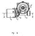
- FIG. 1 shows a power steering according to the invention in a side view.
- This is an embodiment as an electromechanical power steering, in which the steering column is driven by the servo motor.
- This design is called Coloumn-Drive.
- FIG. 1 the transmission of the power steering with a transmission housing 1, in which a steering column 2 is rotatably mounted.
- a worm wheel is mounted, which is coaxially rotatably connected to the steering column 2.
- the worm wheel meshes with a worm shaft arranged in a housing region 3. This in turn is drivingly connected to an electric servomotor, which is arranged in a part housing 4.
- the sub-housing 4 is arranged adjustable with respect to the housing portion 3 in the radial direction of the worm shaft.
- a flange 5 is provided in which an eccentric sleeve 6 the connection and the radial adjustment of the housing part 4 relative to the housing portion 3 allows.
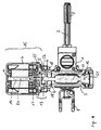
- FIG. 2 shows the power steering FIG. 1 in a 90 ° rotated side view. Same components bear the same reference numbers.
- the steering column 2 is visible in its side view. It is a section of the entire steering column, which is provided on the one hand with a multi-tooth 7 for rotationally fixed connection with a steering wheel and on the other hand with a fork 8 for gimbal connection with the input shaft of a known steering gear, for example of the type of rack and pinion steering.
- FIG. 3 is the power steering off FIG. 1 and 2 in a cross section along the line III-III FIG. 2 shown.
- a worm wheel 10 is rotatably connected in a conventional manner with the steering column 2 and indirectly mounted in the housing 1 via the steering column.
- the worm wheel 10 meshes with a worm shaft 11, which is mounted at its free end in a radial deep groove ball bearing 12.
- the steering shaft 11 is drivingly coupled via a coupling 13 to a motor shaft 14 of a servomotor, designated as a whole by 15.
- the motor shaft 14 is mounted in a coupling remote ball bearing 16 and a clutch bearing close 17 in the housing part 4.
- Screws 18 secure the sub-housing 4 to the transmission housing 3 in the region of the flange 5.
- the sub-housing 4 is adjustable to a small extent relative to the transmission housing 3.
- the eccentric sleeve 6 is mounted on the one hand eccentrically to a rotational axis 21 of the worm shaft 11 in a bore 22 of the gear housing 3 on the one hand.
- the eccentric sleeve 6 is mounted concentrically with the motor shaft 14, which defines a second axis of rotation 24, in a corresponding bore 25 of the housing part 4.
- the eccentric sleeve 6 has a number of blind holes 26 which with a pin or Hook wrench for rotation of the eccentric sleeve 6 can be taken.
- blind holes 26 In an alternative embodiment may be provided instead of the blind holes 26, a hexagon or other shape for engagement of a tool, such as a wrench, on the outer circumference.
- FIG. 4 shows the power steering described so far in a cross section along the line IV-IV FIG. 1 , In this viewing direction, the engagement between the worm shaft 11 and the worm wheel 10 below the worm shaft 11 is hidden by the worm shaft 11 and is in the FIG. 4 not visible.
- the worm shaft 11 For a delivery of the worm shaft 11 to the worm wheel 10, the worm shaft 11 must be displaced in the region of engagement perpendicular to the plane of the drawing. The escape of the two axes of rotation 21 and 24 is not changed.
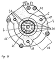
- FIG. 5 shows a further cross section through the power steering along the line VV FIG. 2 the section runs through the flange 5, which coincides with the drawing planes in this illustration.
- the FIG. 5 shows how the eccentric sleeve 6 is inserted into the bore 25 and that the clutch 13 and the coaxial with the clutch motor shaft are concentric with the eccentric sleeve 6.
- the coupling 13 is essentially in three parts.
- the first part is an arrangement of four jaws 30, which are arranged at an angular distance of 90 ° about the axis of rotation 24 of the motor shaft.
- the second part is also formed by four claws 31, which are connected to the worm shaft 11 and are arranged at an angular distance of also 90 ° about the axis of rotation 21 of the worm shaft 11.
- the third element of the dog clutch is a star-shaped elastic coupling element 32 that fills the gap between the jaws 30 and 31.
- the elastic coupling element 32 is in the FIG. 6 shown in perspective.
- the elastic coupling element is preferably formed by an elastomer. But it can also be used plastic or resilient metal elements.
- the engagement of the worm wheel 10 and the worm shaft 11 is shown as an overlap of the two components.
- the two components form a worm gear.
- the worm shaft 11 is displaceable in the direction of the worm wheel 10, in this embodiment, both adjustable and resiliently spring-loaded.
- the coupling 13 between the motor shaft 14 and the worm shaft 11 is basically of the type of compensating couplings and in this particular case of the type of an elastic dog clutch, which is able to compensate for an angular difference between the two axes of rotation 21 and 24, an axial offset and possibly also an axial clearance ,
- the worm shaft 11 is cantilevered in the clutch 13.
- the procedure during assembly is such that the steering column 2, the worm wheel 10 and the worm shaft 11 with the associated bearings are first mounted in the transmission housing 3.
- the eccentric sleeve 6 is inserted into the eccentric bore 22. So then the servo motor 15 is mounted with its sub-housing 4.
- the motor-side jaw 30 is rotatably connected to the motor shaft 14 or is integrally formed on this motor shaft.
- the worm shaft 11 associated claw 31 is mounted on the worm shaft.
- the elastic coupling element preferably the elastomer 32 is placed on one of the two jaws and the sub-housing 4 in the region of the flange 5 is placed on the transmission housing 3 such that the eccentric sleeve 6 can be inserted into the bore 25, which is concentric with the motor shaft 14, of the part housing 4 and that the respective other jaw of the coupling 13 engages in the remaining intermediate spaces of the elastomer 32.
- the three threaded screws 18 can then be first screwed into the housing part 4 so far that the motor in the flange 5 is just still displaceable relative to the transmission housing 3.
- the through holes of the gear housing 3 penetrated by the threaded screws 18 are correspondingly enlarged in diameter or designed as elongated holes.
- a rotation of the eccentric sleeve 6 now causes a parallel displacement of the axis of rotation 24 of the motor shaft 14 and the clutch 13 takes the cantilevered end of the worm shaft 11 with it.
- the worm shaft 11 is fixedly supported in the gear housing 3 in the radial ball bearing 12, so that the inclination of the rotation shaft 21 of the worm shaft 11 changes.
- the electric motor 15 is then supplied with current and thus caused to rotate the motor shaft. This takes over the clutch 13, the worm shaft 11 and rotates about the engagement of the teeth, the worm wheel 10. With a hook wrench, which engages in the holes 26 of the eccentric sleeve 6, this is rotated in the bores 22 and 25. The worm shaft 11 is thereby brought closer to the worm wheel 10 or removed from the worm wheel 10, depending on the position of the eccentric sleeve 6. A measurement of the current consumption of the electric motor 15 or an alternative measurement of the drive torque of the worm shaft 11 are in this process an indication of the friction generated in the transmission.
- An optimal adjustment of the engagement on the eccentric sleeve 6 is depending on the specific embodiment of the transmission approximately in the area in which the friction begins to increase, which can be seen by an increasing current consumption of the electric motor 15. Transmissions of this type are not necessarily symmetrical with regard to the direction of rotation. Therefore, it is preferable to make the adjustment of the engagement between the worm shaft 11 and the worm wheel 10 such that both rotational directions of the electric motor 15 are taken into consideration. For this purpose, the direction of rotation is intermittently reversed and a compromise between the two possibly mismatched optimal settings of the eccentric sleeve 6 is sought for both directions of rotation.
- the adjustment range which is made possible by the eccentricity of the eccentric sleeve 6, ie the region in which the subhousing 4 can be moved relative to the gearbox housing 3 in the plane of the flange 5, can be selected within the largest expected manufacturing tolerance for the worm shaft 11 and the worm wheel 10 become.
- a usable adjustment range of about +/- 0.1 mm should be sufficient in practice.
- the elastomer 32 will not develop "settling" since it is not statically loaded in one direction, but the load direction is constantly circulated during operation. If, over time, a noise that suggests a match between the worm shaft 11 and the worm wheel 10, the screws 18 can be solved and the game setting on the eccentric sleeve 6 are made again.
- All embodiments have in common that the springing and the compensation of the angular difference between the two axes of rotation 21 and 24 and a possible axial offset in the radial direction in a component, namely the compensation clutch 13 takes place.
- the adjustment by relative displacement of the housing part 4 and the gear housing 3 allows readjustment in case of repair.
Landscapes
- Engineering & Computer Science (AREA)
- Chemical & Material Sciences (AREA)
- Combustion & Propulsion (AREA)
- Transportation (AREA)
- Mechanical Engineering (AREA)
- Power Steering Mechanism (AREA)
- Gear Transmission (AREA)
- Steering Control In Accordance With Driving Conditions (AREA)
- Retarders (AREA)
- Vibration Prevention Devices (AREA)
- Springs (AREA)
Claims (7)
- Système de direction comprenant un moteur (15) qui est relié en termes d'entraînement à un arbre de vis sans fin (11) via un arbre moteur (14) et un coupleur de compensation (13), l'arbre de vis sans fin (11) étant en engrènement avec une vis tangente (10) et dans lequel- le moteur (15), l'arbre de vis sans fin (11) et la vis tangente (10) sont montés dans un boîtier de transmission (1),- l'arbre moteur (14) et l'arbre de vis sans fin (11) définissent chacun un axe de rotation (24, 21),- l'arbre moteur (14) est monté, avec un palier moteur respectif (17) proche du coupleur et avec un palier moteur (16) éloigné du coupleur, dans un boîtier partiel (4) déplaçable par rapport au boîtier de transmission (1), et- l'arbre de vis sans fin (11) est monté à son extrémité éloignée du coupleur dans un palier (12) et à son extrémité proche du coupleur dans le coupleur (13),caractérisé en ce que- le moteur (15) avec le boîtier partiel (4) est susceptible d'être ajusté en position en direction radiale de son axe de rotation (24).
- Direction assistée selon la revendication 1, caractérisée en ce que le boîtier partiel (4) est monté sur le boîtier de transmission (1) dans un siège rotatif (22) excentré par rapport à l'arbre moteur (14).
- Direction assistée selon la revendication 2, caractérisée en ce que le siège (22) est réalisé de façon à coopérer avec une douille excentrique (6) qui, lorsque le boîtier partiel (4) est monté solidairement en rotation mais radialement déplaçable, est susceptible d'être mise en rotation de l'extérieur.
- Direction assistée selon l'une des revendications précédentes, caractérisée en ce que le boîtier partiel (4) présente sur le boîtier de transmission (1) une plage d'ajustement en direction radiale inférieure à 1 mm.
- Direction assistée selon l'une des revendications précédentes, caractérisée en ce que le coupleur (13) est un coupleur de compensation rigide en rotation.
- Direction assistée selon l'une des revendications précédentes 1 à 3, caractérisée en ce que le coupleur (13) est un coupleur de compensation élastique.
- Direction assistée selon la revendication 6, caractérisée en ce que le coupleur (13) est un coupleur à griffes avec un élastomère (32) élastique vis-à-vis de la pression, inséré entre les griffes (30, 31).
Priority Applications (1)
| Application Number | Priority Date | Filing Date | Title |
|---|---|---|---|
| PL06723812T PL1866196T3 (pl) | 2005-04-04 | 2006-03-29 | Elektromechaniczny układ wspomagania kierownicy |
Applications Claiming Priority (2)
| Application Number | Priority Date | Filing Date | Title |
|---|---|---|---|
| DE102005015451A DE102005015451A1 (de) | 2005-04-04 | 2005-04-04 | Elektromechanische Servolenkung |
| PCT/EP2006/002843 WO2006105900A1 (fr) | 2005-04-04 | 2006-03-29 | Servodirection electromecanique |
Publications (2)
| Publication Number | Publication Date |
|---|---|
| EP1866196A1 EP1866196A1 (fr) | 2007-12-19 |
| EP1866196B1 true EP1866196B1 (fr) | 2008-10-29 |
Family
ID=36570350
Family Applications (1)
| Application Number | Title | Priority Date | Filing Date |
|---|---|---|---|
| EP06723812A Active EP1866196B1 (fr) | 2005-04-04 | 2006-03-29 | Servodirection electromecanique |
Country Status (7)
| Country | Link |
|---|---|
| US (1) | US20080149413A1 (fr) |
| EP (1) | EP1866196B1 (fr) |
| AT (1) | ATE412568T1 (fr) |
| DE (2) | DE102005015451A1 (fr) |
| ES (1) | ES2317514T3 (fr) |
| PL (1) | PL1866196T3 (fr) |
| WO (1) | WO2006105900A1 (fr) |
Families Citing this family (11)
| Publication number | Priority date | Publication date | Assignee | Title |
|---|---|---|---|---|
| KR100723732B1 (ko) * | 2005-11-02 | 2007-05-30 | 주식회사 만도 | 웜 기어 유격 보상 장치를 구비한 전동식 동력 보조조향장치 |
| DE102008009060B4 (de) | 2008-02-13 | 2010-01-14 | Thyssenkrupp Presta Ag | Elektrische Servolenkung mit angetriebener Lenkwelle |
| KR20090120762A (ko) * | 2008-05-20 | 2009-11-25 | 현대자동차주식회사 | 전동식 파워 스티어링의 플렉시블 커플링 |
| DE102008036753A1 (de) | 2008-08-07 | 2010-02-18 | Thyssenkrupp Presta Ag | Kreuzgelenk |
| US9664273B2 (en) | 2012-08-07 | 2017-05-30 | Steering Solutions Ip Holding Corporation | Steering column assist system |
| US9533701B2 (en) | 2012-08-07 | 2017-01-03 | Steering Solutions Ip Holding Corporation | Steering column assist system |
| DE102013007883A1 (de) | 2013-05-08 | 2014-11-13 | Thyssenkrupp Presta Ag | Anfederungs-Exzenterschwinge in CEPS-Anwendung |
| CN103465953A (zh) * | 2013-09-27 | 2013-12-25 | 太仓康茂电子有限公司 | 一种减速机构 |
| EP3072785B1 (fr) * | 2015-03-26 | 2019-05-08 | Steering Solutions IP Holding Corporation | Systeme d'assistance de colonne de direction |
| KR101701042B1 (ko) * | 2015-05-29 | 2017-01-31 | 현대위아 주식회사 | 기어 백래시 조정장치 |
| KR101702765B1 (ko) * | 2015-08-13 | 2017-02-03 | 주식회사 만도 | 유성기어 감속기 |
Family Cites Families (14)
| Publication number | Priority date | Publication date | Assignee | Title |
|---|---|---|---|---|
| DE1480181A1 (de) * | 1965-10-27 | 1969-09-04 | Scheuerle Fahrzeugfabrik Willy | Lenkvorrichtung fuer Nachlaeufer oder Anhaenger eines Schwerlastzuges |
| GB9812844D0 (en) * | 1998-06-16 | 1998-08-12 | Lucas Ind Plc | Improvements relating to electrical power assisted steering |
| US6164407A (en) * | 1998-12-04 | 2000-12-26 | Trw Inc. | Electric power steering apparatus |
| US6155376A (en) * | 1998-12-28 | 2000-12-05 | Trw Inc. | Electric power steering assembly |
| JP3430954B2 (ja) * | 1999-01-25 | 2003-07-28 | トヨタ自動車株式会社 | 電動式パワーステアリング装置 |
| DE10049570A1 (de) * | 1999-10-08 | 2002-04-18 | Honda Motor Co Ltd | Elektrische Servolenkvorrichtung |
| JP2001301630A (ja) * | 2000-04-25 | 2001-10-31 | Showa Corp | 電動パワーステアリング装置 |
| FR2819774B1 (fr) * | 2001-01-19 | 2006-09-29 | Koyo Seiko Co | Articulation et systeme de direction assistee l'utilisant |
| DE10161715A1 (de) * | 2001-12-15 | 2003-06-18 | Zf Lenksysteme Gmbh | Elektrische Hilfskraftlenkung für Kraftfahrzeuge |
| JP4007159B2 (ja) * | 2002-10-30 | 2007-11-14 | 株式会社ジェイテクト | 電動パワーステアリング装置及びジョイント |
| JP3951913B2 (ja) * | 2002-12-24 | 2007-08-01 | 株式会社ジェイテクト | 電動式パワーステアリング装置 |
| JP4145163B2 (ja) * | 2003-02-21 | 2008-09-03 | 株式会社ショーワ | 電動パワーステアリング装置 |
| US7591204B2 (en) * | 2003-05-06 | 2009-09-22 | Nsk Ltd. | Belt speed reducing apparatus for electric power steering apparatus and electric power steering apparatus |
| EP1886899A1 (fr) * | 2006-08-10 | 2008-02-13 | Mando Corporation | Direction assistée électrique équipée d'un mécanisme de réglage de la tension d'une courroie de transmission |
-
2005
- 2005-04-04 DE DE102005015451A patent/DE102005015451A1/de not_active Withdrawn
-
2006
- 2006-03-29 US US11/910,386 patent/US20080149413A1/en not_active Abandoned
- 2006-03-29 AT AT06723812T patent/ATE412568T1/de not_active IP Right Cessation
- 2006-03-29 EP EP06723812A patent/EP1866196B1/fr active Active
- 2006-03-29 PL PL06723812T patent/PL1866196T3/pl unknown
- 2006-03-29 WO PCT/EP2006/002843 patent/WO2006105900A1/fr active Application Filing
- 2006-03-29 ES ES06723812T patent/ES2317514T3/es active Active
- 2006-03-29 DE DE502006001943T patent/DE502006001943D1/de active Active
Also Published As
| Publication number | Publication date |
|---|---|
| DE102005015451A1 (de) | 2006-10-05 |
| ATE412568T1 (de) | 2008-11-15 |
| WO2006105900A1 (fr) | 2006-10-12 |
| ES2317514T3 (es) | 2009-04-16 |
| DE502006001943D1 (de) | 2008-12-11 |
| US20080149413A1 (en) | 2008-06-26 |
| PL1866196T3 (pl) | 2009-04-30 |
| WO2006105900A9 (fr) | 2007-11-15 |
| EP1866196A1 (fr) | 2007-12-19 |
Similar Documents
| Publication | Publication Date | Title |
|---|---|---|
| EP1866196B1 (fr) | Servodirection electromecanique | |
| EP2595854B1 (fr) | Levier de direction à double pignon | |
| EP3464023B1 (fr) | Direction assistée électromécanique à palier pivotant pour un engrenage hélicoïdal | |
| WO2013152995A1 (fr) | Mécanisme de direction | |
| DE10051306A1 (de) | Spielfreies Lenkgetriebe | |
| DE102006042322A1 (de) | Scheibenwischeranlage mit einem Scheibenwischerantrieb, insbesondere für einen Heckscheibenwischer eines Kraftfahrzeugs mit einer modular austauschbaren Getriebeanordnung | |
| DE102013010362B4 (de) | Doppelritzel-Lenkgetriebe mit Hohlwellenmotor | |
| EP3526103A1 (fr) | Direction assistée électromécanique comprenant un agencement de palier à ressort | |
| EP4103451B1 (fr) | Colonne de direction pour un véhicule à moteur | |
| EP3148860A1 (fr) | Arbre de direction d'un véhicule automobile | |
| EP3010784A1 (fr) | Mécanisme de direction à pignon double pourvu d'un moteur électrique | |
| WO2016124299A1 (fr) | Dispositif destiné à appliquer un couple d'assistance à un arbre de direction | |
| DE102013018436A1 (de) | Lenkgetriebe mit mehreren Ritzeln | |
| DE102010032995A1 (de) | Notenriegelung einer motorischen Verschließvorrichtung | |
| WO2019238574A1 (fr) | Colonne de direction équipée d'un actionneur | |
| WO2016139214A1 (fr) | Arbre d'entrée monobloc | |
| WO2009027410A1 (fr) | Dispositif d'entraînement | |
| EP3850246B1 (fr) | Transmission | |
| WO2004016481A1 (fr) | Dispositif d'essuie-glace, notamment pour vehicules | |
| DE4340203C2 (de) | Elektrisch angetriebene Lenkvorrichtung | |
| EP3898381A1 (fr) | Entraînement de puissance auxiliaire pour colonne de direction et colonne de direction pour véhicule automobile | |
| DE102005021042B4 (de) | Welle-Nabe-Verbindung, insbesondere einer Kraftfahrzeuglenkung | |
| EP1482118B1 (fr) | Entraînement pour un battant articulé ou basculant | |
| DE102014108948B3 (de) | Servolenkbaugruppe mit Lenkmomentüberlagerung | |
| DE102019119128A1 (de) | Lenkgetriebe für ein Kraftfahrzeug |
Legal Events
| Date | Code | Title | Description |
|---|---|---|---|
| PUAI | Public reference made under article 153(3) epc to a published international application that has entered the european phase |
Free format text: ORIGINAL CODE: 0009012 |
|
| AK | Designated contracting states |
Kind code of ref document: A1 Designated state(s): AT BE BG CH CY CZ DE DK EE ES FI FR GB GR HU IE IS IT LI LT LU LV MC NL PL PT RO SE SI SK TR |
|
| 17P | Request for examination filed |
Effective date: 20071022 |
|
| 17Q | First examination report despatched |
Effective date: 20080125 |
|
| GRAP | Despatch of communication of intention to grant a patent |
Free format text: ORIGINAL CODE: EPIDOSNIGR1 |
|
| DAX | Request for extension of the european patent (deleted) | ||
| GRAS | Grant fee paid |
Free format text: ORIGINAL CODE: EPIDOSNIGR3 |
|
| GRAA | (expected) grant |
Free format text: ORIGINAL CODE: 0009210 |
|
| AK | Designated contracting states |
Kind code of ref document: B1 Designated state(s): AT BE BG CH CY CZ DE DK EE ES FI FR GB GR HU IE IS IT LI LT LU LV MC NL PL PT RO SE SI SK TR |
|
| REG | Reference to a national code |
Ref country code: GB Ref legal event code: FG4D Free format text: NOT ENGLISH |
|
| REG | Reference to a national code |
Ref country code: CH Ref legal event code: EP |
|
| REG | Reference to a national code |
Ref country code: IE Ref legal event code: FG4D Free format text: LANGUAGE OF EP DOCUMENT: GERMAN |
|
| REF | Corresponds to: |
Ref document number: 502006001943 Country of ref document: DE Date of ref document: 20081211 Kind code of ref document: P |
|
| NLV1 | Nl: lapsed or annulled due to failure to fulfill the requirements of art. 29p and 29m of the patents act | ||
| REG | Reference to a national code |
Ref country code: ES Ref legal event code: FG2A Ref document number: 2317514 Country of ref document: ES Kind code of ref document: T3 |
|
| LTIE | Lt: invalidation of european patent or patent extension |
Effective date: 20081029 |
|
| PG25 | Lapsed in a contracting state [announced via postgrant information from national office to epo] |
Ref country code: BG Free format text: LAPSE BECAUSE OF FAILURE TO SUBMIT A TRANSLATION OF THE DESCRIPTION OR TO PAY THE FEE WITHIN THE PRESCRIBED TIME-LIMIT Effective date: 20090129 Ref country code: LT Free format text: LAPSE BECAUSE OF FAILURE TO SUBMIT A TRANSLATION OF THE DESCRIPTION OR TO PAY THE FEE WITHIN THE PRESCRIBED TIME-LIMIT Effective date: 20081029 |
|
| REG | Reference to a national code |
Ref country code: PL Ref legal event code: T3 |
|
| PG25 | Lapsed in a contracting state [announced via postgrant information from national office to epo] |
Ref country code: PT Free format text: LAPSE BECAUSE OF FAILURE TO SUBMIT A TRANSLATION OF THE DESCRIPTION OR TO PAY THE FEE WITHIN THE PRESCRIBED TIME-LIMIT Effective date: 20090330 Ref country code: IS Free format text: LAPSE BECAUSE OF FAILURE TO SUBMIT A TRANSLATION OF THE DESCRIPTION OR TO PAY THE FEE WITHIN THE PRESCRIBED TIME-LIMIT Effective date: 20090228 Ref country code: LV Free format text: LAPSE BECAUSE OF FAILURE TO SUBMIT A TRANSLATION OF THE DESCRIPTION OR TO PAY THE FEE WITHIN THE PRESCRIBED TIME-LIMIT Effective date: 20081029 Ref country code: NL Free format text: LAPSE BECAUSE OF FAILURE TO SUBMIT A TRANSLATION OF THE DESCRIPTION OR TO PAY THE FEE WITHIN THE PRESCRIBED TIME-LIMIT Effective date: 20081029 Ref country code: SI Free format text: LAPSE BECAUSE OF FAILURE TO SUBMIT A TRANSLATION OF THE DESCRIPTION OR TO PAY THE FEE WITHIN THE PRESCRIBED TIME-LIMIT Effective date: 20081029 Ref country code: FI Free format text: LAPSE BECAUSE OF FAILURE TO SUBMIT A TRANSLATION OF THE DESCRIPTION OR TO PAY THE FEE WITHIN THE PRESCRIBED TIME-LIMIT Effective date: 20081029 |
|
| REG | Reference to a national code |
Ref country code: IE Ref legal event code: FD4D |
|
| PG25 | Lapsed in a contracting state [announced via postgrant information from national office to epo] |
Ref country code: IE Free format text: LAPSE BECAUSE OF FAILURE TO SUBMIT A TRANSLATION OF THE DESCRIPTION OR TO PAY THE FEE WITHIN THE PRESCRIBED TIME-LIMIT Effective date: 20081029 Ref country code: RO Free format text: LAPSE BECAUSE OF FAILURE TO SUBMIT A TRANSLATION OF THE DESCRIPTION OR TO PAY THE FEE WITHIN THE PRESCRIBED TIME-LIMIT Effective date: 20081029 Ref country code: DK Free format text: LAPSE BECAUSE OF FAILURE TO SUBMIT A TRANSLATION OF THE DESCRIPTION OR TO PAY THE FEE WITHIN THE PRESCRIBED TIME-LIMIT Effective date: 20081029 Ref country code: EE Free format text: LAPSE BECAUSE OF FAILURE TO SUBMIT A TRANSLATION OF THE DESCRIPTION OR TO PAY THE FEE WITHIN THE PRESCRIBED TIME-LIMIT Effective date: 20081029 |
|
| PG25 | Lapsed in a contracting state [announced via postgrant information from national office to epo] |
Ref country code: SE Free format text: LAPSE BECAUSE OF FAILURE TO SUBMIT A TRANSLATION OF THE DESCRIPTION OR TO PAY THE FEE WITHIN THE PRESCRIBED TIME-LIMIT Effective date: 20090129 |
|
| PLBE | No opposition filed within time limit |
Free format text: ORIGINAL CODE: 0009261 |
|
| STAA | Information on the status of an ep patent application or granted ep patent |
Free format text: STATUS: NO OPPOSITION FILED WITHIN TIME LIMIT |
|
| BERE | Be: lapsed |
Owner name: THYSSENKRUPP PRESTA AG Effective date: 20090331 |
|
| PG25 | Lapsed in a contracting state [announced via postgrant information from national office to epo] |
Ref country code: SK Free format text: LAPSE BECAUSE OF FAILURE TO SUBMIT A TRANSLATION OF THE DESCRIPTION OR TO PAY THE FEE WITHIN THE PRESCRIBED TIME-LIMIT Effective date: 20081029 |
|
| 26N | No opposition filed |
Effective date: 20090730 |
|
| PG25 | Lapsed in a contracting state [announced via postgrant information from national office to epo] |
Ref country code: MC Free format text: LAPSE BECAUSE OF NON-PAYMENT OF DUE FEES Effective date: 20090331 |
|
| PG25 | Lapsed in a contracting state [announced via postgrant information from national office to epo] |
Ref country code: BE Free format text: LAPSE BECAUSE OF NON-PAYMENT OF DUE FEES Effective date: 20090331 |
|
| PG25 | Lapsed in a contracting state [announced via postgrant information from national office to epo] |
Ref country code: AT Free format text: LAPSE BECAUSE OF NON-PAYMENT OF DUE FEES Effective date: 20090329 |
|
| PG25 | Lapsed in a contracting state [announced via postgrant information from national office to epo] |
Ref country code: GR Free format text: LAPSE BECAUSE OF FAILURE TO SUBMIT A TRANSLATION OF THE DESCRIPTION OR TO PAY THE FEE WITHIN THE PRESCRIBED TIME-LIMIT Effective date: 20090130 |
|
| REG | Reference to a national code |
Ref country code: CH Ref legal event code: PL |
|
| PG25 | Lapsed in a contracting state [announced via postgrant information from national office to epo] |
Ref country code: LI Free format text: LAPSE BECAUSE OF NON-PAYMENT OF DUE FEES Effective date: 20100331 Ref country code: CH Free format text: LAPSE BECAUSE OF NON-PAYMENT OF DUE FEES Effective date: 20100331 |
|
| PG25 | Lapsed in a contracting state [announced via postgrant information from national office to epo] |
Ref country code: LU Free format text: LAPSE BECAUSE OF NON-PAYMENT OF DUE FEES Effective date: 20090329 |
|
| PG25 | Lapsed in a contracting state [announced via postgrant information from national office to epo] |
Ref country code: HU Free format text: LAPSE BECAUSE OF FAILURE TO SUBMIT A TRANSLATION OF THE DESCRIPTION OR TO PAY THE FEE WITHIN THE PRESCRIBED TIME-LIMIT Effective date: 20090430 |
|
| PG25 | Lapsed in a contracting state [announced via postgrant information from national office to epo] |
Ref country code: TR Free format text: LAPSE BECAUSE OF FAILURE TO SUBMIT A TRANSLATION OF THE DESCRIPTION OR TO PAY THE FEE WITHIN THE PRESCRIBED TIME-LIMIT Effective date: 20081029 |
|
| PG25 | Lapsed in a contracting state [announced via postgrant information from national office to epo] |
Ref country code: CY Free format text: LAPSE BECAUSE OF FAILURE TO SUBMIT A TRANSLATION OF THE DESCRIPTION OR TO PAY THE FEE WITHIN THE PRESCRIBED TIME-LIMIT Effective date: 20081029 |
|
| REG | Reference to a national code |
Ref country code: FR Ref legal event code: PLFP Year of fee payment: 11 |
|
| REG | Reference to a national code |
Ref country code: FR Ref legal event code: PLFP Year of fee payment: 12 |
|
| REG | Reference to a national code |
Ref country code: FR Ref legal event code: PLFP Year of fee payment: 13 |
|
| REG | Reference to a national code |
Ref country code: DE Ref legal event code: R081 Ref document number: 502006001943 Country of ref document: DE Owner name: THYSSENKRUPP PRESTA AKTIENGESELLSCHAFT, LI Free format text: FORMER OWNER: THYSSENKRUPP PRESTA AKTIENGESELLSCHAFT, ESCHEN, LI |
|
| PGFP | Annual fee paid to national office [announced via postgrant information from national office to epo] |
Ref country code: GB Payment date: 20220321 Year of fee payment: 17 |
|
| PGFP | Annual fee paid to national office [announced via postgrant information from national office to epo] |
Ref country code: PL Payment date: 20220216 Year of fee payment: 17 Ref country code: IT Payment date: 20220322 Year of fee payment: 17 Ref country code: FR Payment date: 20220322 Year of fee payment: 17 |
|
| PGFP | Annual fee paid to national office [announced via postgrant information from national office to epo] |
Ref country code: ES Payment date: 20220527 Year of fee payment: 17 Ref country code: CZ Payment date: 20220329 Year of fee payment: 17 |
|
| REG | Reference to a national code |
Ref country code: DE Ref legal event code: R084 Ref document number: 502006001943 Country of ref document: DE |
|
| PG25 | Lapsed in a contracting state [announced via postgrant information from national office to epo] |
Ref country code: CZ Free format text: LAPSE BECAUSE OF NON-PAYMENT OF DUE FEES Effective date: 20230329 |
|
| GBPC | Gb: european patent ceased through non-payment of renewal fee |
Effective date: 20230329 |
|
| PG25 | Lapsed in a contracting state [announced via postgrant information from national office to epo] |
Ref country code: GB Free format text: LAPSE BECAUSE OF NON-PAYMENT OF DUE FEES Effective date: 20230329 |
|
| PG25 | Lapsed in a contracting state [announced via postgrant information from national office to epo] |
Ref country code: GB Free format text: LAPSE BECAUSE OF NON-PAYMENT OF DUE FEES Effective date: 20230329 Ref country code: FR Free format text: LAPSE BECAUSE OF NON-PAYMENT OF DUE FEES Effective date: 20230331 |
|
| PG25 | Lapsed in a contracting state [announced via postgrant information from national office to epo] |
Ref country code: IT Free format text: LAPSE BECAUSE OF NON-PAYMENT OF DUE FEES Effective date: 20230329 |
|
| PGFP | Annual fee paid to national office [announced via postgrant information from national office to epo] |
Ref country code: DE Payment date: 20240320 Year of fee payment: 19 |
|
| REG | Reference to a national code |
Ref country code: ES Ref legal event code: FD2A Effective date: 20240503 |
|
| PG25 | Lapsed in a contracting state [announced via postgrant information from national office to epo] |
Ref country code: ES Free format text: LAPSE BECAUSE OF NON-PAYMENT OF DUE FEES Effective date: 20230330 |
|
| PG25 | Lapsed in a contracting state [announced via postgrant information from national office to epo] |
Ref country code: ES Free format text: LAPSE BECAUSE OF NON-PAYMENT OF DUE FEES Effective date: 20230330 |
|
| PG25 | Lapsed in a contracting state [announced via postgrant information from national office to epo] |
Ref country code: PL Free format text: LAPSE BECAUSE OF NON-PAYMENT OF DUE FEES Effective date: 20230329 |
|
| PG25 | Lapsed in a contracting state [announced via postgrant information from national office to epo] |
Ref country code: PL Free format text: LAPSE BECAUSE OF NON-PAYMENT OF DUE FEES Effective date: 20230329 |