EP1864603B1 - Dishwasher with heat recovery - Google Patents
Dishwasher with heat recovery Download PDFInfo
- Publication number
- EP1864603B1 EP1864603B1 EP20070011659 EP07011659A EP1864603B1 EP 1864603 B1 EP1864603 B1 EP 1864603B1 EP 20070011659 EP20070011659 EP 20070011659 EP 07011659 A EP07011659 A EP 07011659A EP 1864603 B1 EP1864603 B1 EP 1864603B1
- Authority
- EP
- European Patent Office
- Prior art keywords
- water
- heat
- phase
- heat transfer
- process water
- Prior art date
- Legal status (The legal status is an assumption and is not a legal conclusion. Google has not performed a legal analysis and makes no representation as to the accuracy of the status listed.)
- Active
Links
Images


Classifications
-
- A—HUMAN NECESSITIES
- A47—FURNITURE; DOMESTIC ARTICLES OR APPLIANCES; COFFEE MILLS; SPICE MILLS; SUCTION CLEANERS IN GENERAL
- A47L—DOMESTIC WASHING OR CLEANING; SUCTION CLEANERS IN GENERAL
- A47L15/00—Washing or rinsing machines for crockery or tableware
- A47L15/42—Details
- A47L15/4291—Recovery arrangements, e.g. for the recovery of energy or water
-
- A—HUMAN NECESSITIES
- A47—FURNITURE; DOMESTIC ARTICLES OR APPLIANCES; COFFEE MILLS; SPICE MILLS; SUCTION CLEANERS IN GENERAL
- A47L—DOMESTIC WASHING OR CLEANING; SUCTION CLEANERS IN GENERAL
- A47L15/00—Washing or rinsing machines for crockery or tableware
- A47L15/42—Details
- A47L15/4229—Water softening arrangements
- A47L15/4231—Constructional details of the salt container or the ion exchanger
Definitions
- the invention relates to a dishwasher with heat recovery according to the preamble of claim 1.
- the dishes to be washed are cleaned with process water in several consecutive process phases.
- the water is heated in at least two of these process phases.
- DE-A-3 901 169 discloses a dishwasher with such a heat storage and DE-U-29518630 discloses a dishwasher with a water decalcifying device.
- the dishwasher thus has heat transfer means which are able to transfer heat between the process water and the water decalcification device of the device.
- the heat transfer means are controlled by the controller of the dishwasher in such a way that they transport heat from the process water into the water decalcifier in a first process phase in order to then transport this heat from the water decalcifier back into the process water in a second, later process phase.
- the Wasserentkalkungsvortechnische the device is used as a heat storage. Since this has a relatively large thermal mass and is present anyway in each device, it is particularly suitable as a buffer for heat. Thus, a separate heat storage omitted entirely or at least smaller.
- the Wasserentkalkungsvoriques has a brine tank for receiving brine.
- the heat transfer means are configured to transfer heat between that received in the brine tank Solewasser and the process water can transfer.
- the brine water is used as a heat storage.
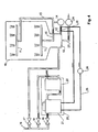
- the in Fig. 1 shown dishwasher has a tub 10 for receiving the dishes to be washed.
- spray arms 11 or other spray devices are arranged in a conventional manner, with which process water can be sprayed onto the dishes.
- a process water circuit is connected, with which the process water can be pumped.
- This has a suction tube 12, with which the water can be sucked out of the sump 13 of the tub. From the suction pipe 12, the water passes to a pump 14, from where it is conveyed via lines 15 to the spray arms 11.
- a supply line 16 is provided, from which water via three valves 17, 18, 19 can be tapped. These valves, as well as all other functions and components of the device, are controlled by a controller (not shown).
- valve 17 By opening the first valve 17 fresh water can be passed directly into the sump 13 of the tub 10. Alternatively or additionally, by opening the second valve 18 water via a Wasserentkalkungsvoriques 20 also in the sump 13th be initiated.
- the valve 17 and the corresponding supply line can also be omitted in simple models.
- the desalination apparatus 20 comprises a brine container 21 and a resin container 22.
- an ion exchange resin is arranged, with which water can be softened in a conventional manner.
- brine tank 21 is provided with brine water. These are usually salt water. By opening the third valve 19, the brine water can be passed through the resin container 22 so as to perform regeneration.
- the device For discharging contaminated process water, the device has a drain 23 with a drain pump 24.
- heat transfer agents are provided, which are described below.
- the heat transfer means comprise a transfer circuit 25, which is shown with a bold line.
- a heat transfer medium is pumped by a circulation pump 26 between a first heat exchanger 28 and a second heat exchanger 29.
- the heat transfer medium may be, for example, water or another fluid.
- the first heat exchanger 28 is arranged at the process water circuit, while the second heat exchanger 29 is located at the Wasserentkalkungsvoriques 20.
- the first heat exchanger 28 is thermally connected to the suction pipe 12, and the second heat exchanger 29 to the brine tank 21st
- the dishes are pre-rinsed in a first process phase, the pre-rinse phase.
- the process water is pumped off and fresh water is supplied for the following main cleaning phase. This is pumped by the pump 14 and heated by a (not shown) heater. At the same time a dishwashing detergent is added.
- the heat transfer means are used to transfer heat via the water decalcification device 20 from a first process phase to a later, second process phase.
- first process phase and second process phase designate those process phases in which heat is transferred between the process water and the descaling device - the terms are not to be interpreted as meaning that the first process phase is necessarily the process phase that is carried out at the beginning of the cleaning process, and the second process phase does not necessarily follow directly to the first phase of the process.
- the removal of heat takes place as possible towards the end of the first process phase before or during the pumping out of the process water.
- the pumps 14 and 26 are put into operation, for example, during 2 to 3 minutes, so that the heated process water flows through the suction pipe 12 there to give heat in the first heat exchanger 28 to the heat transfer medium.
- the heated heat transfer medium is conveyed by the pump 26 to the second heat exchanger 29, where it in turn emits heat to the Wasserentkalkungsvortechnisch 20 and in particular to the brine.
- the first process phase, from which the heat is extracted is the main cleaning phase, as this is usually the first phase in which the process water is heated to a high temperature.
- the process water is at least partially replaced by fresh water, whereby the temperature in the tub decreases. It may then optionally follow one or more process phases in which the pump 26 remains switched off and the heat is stored in the descaling device 20. If the first process phase is e.g. the main cleaning phase, the pump 26 may be switched off in the following intermediate flushing phase.
- the heat transfer from the desalination device 20 to the process water preferably takes place at the beginning of the second process phase by switching on the pumps 14 and 26.
- the pump 26 is operated, for example, as long as the temperature of the transfer medium is higher by a threshold than that of the process water.
- heat can also be supplied to the process water with a heater arranged in the process water circuit.
- the heater is activated only after completion of the heat transfer, since otherwise the Wasserentkalkungsvorraum less heat can be removed.
- the pump 14 is preferably operated at reduced power, so that the process water exits only via the lower spray arm and does not act on the dishes. This allows a larger amount of heat to be transferred from the water decalcification device, as if the process water already ran during the heat transfer over the hot dishes and would heat up in this way faster. Only after completion of the heat transfer, the pump is operated with higher power.
- a second embodiment of the invention is in Fig. 2 shown. This differs from the execution Fig. 1 in that the first heat exchanger 28 is not arranged on the suction tube 12 but on one of the lines 15 downstream of the pump 14. Preferably, the first heat exchanger 28 is in this case on the line to the lower spray arm, so that in the manner already described during the heat transfer in the second process phase, the pump 14 can be operated with reduced power.
- a third embodiment of the invention is disclosed in Fig. 3 shown. It differs from the execution Fig. 1 in that no separate circuit is provided for a heat transfer medium. Rather, the heat transfer means are designed so that they can direct process water through the second heat exchanger 29. For this purpose, a changeover switch 32 is provided in the process water circuit, with which the process water can be selectively guided either directly to the spray arms 11 or first through the second heat exchanger 29 and only then to the spray arms 11.
- the process water from the controller of the device is passed through the second heat exchanger 29, while in normal operation of the device, the switch 32 is set so that the water from the pump 14 directly to the spray arms 11th flows.
- Switch 32 may also be continuously controllable and, for example, conduct only a portion of the water through the heat exchanger 29.
- the first heat exchanger and the pump 26 can be omitted.
- a fourth embodiment of the invention is in Fig. 4 shown. It differs from the execution Fig. 1 again in that no separate circuit is provided for a heat transfer medium.
- the heat transfer means are configured so that they can convey brine through the first heat exchanger 28. For this purpose, the brine from the brine tank 21 with the pump 26 to the first heat exchanger 28 and then be promoted back.
- the second heat exchanger can be omitted.
- the first heat exchanger 28 also, as in the embodiment according to Fig. 2 shown to be arranged after the pump 14.
- the heat capacity of the water descaling device 20 can be increased by selecting the brine container larger than conventional devices, and e.g. is set at 2 to 3 liters.
- a thermal insulation is arranged around the brine tank 21, so that the heat can be stored longer in the water decalcification device 20.
- the first heat exchanger 28 can also be arranged at the outlet 23, so that the heat transfer from the process water to the water decalcification device 20 takes place only when pumping off at the end of the first process phase.
- the supply line for the process water can be passed through a heat exchanger which is in contact with the Wasserentkalkungsvortechnik 20.
- it can additionally be arranged a heat exchanger in the process water circuit.
- the first heat exchanger 28 can also be arranged on the sump 13 or elsewhere on the tub 11.
- the heat transfer means are equipped with a transfer circuit 25 for a heat transfer medium.
- the heat transfer agent can also be configured as an actual heat pump by an expansion valve is provided between the two heat exchangers 28 and 29 in a conventional manner, so that (depending on the direction of the pump 26) one of the two heat exchangers as evaporator and the other Capacitor works. This makes it possible to improve the heat transfer efficiency.
- the brine tank 21 and the brine placed therein act as heat storage.
- the resin container 22 and the water therein can be used as a heat storage.
Description
Die Erfindung betrifft einen Geschirrspüler mit Wärmerückgewinnung gemäss Oberbegriff von Anspruch 1.The invention relates to a dishwasher with heat recovery according to the preamble of claim 1.
In Geschirrspülern wird das zu spülende Geschirr in mehreren, aufeinander folgenden Prozessphasen mit Prozesswasser gereinigt. In der Regel wird das Wasser in mindestens zwei dieser Prozessphasen erwärmt.In dishwashers, the dishes to be washed are cleaned with process water in several consecutive process phases. As a rule, the water is heated in at least two of these process phases.
Um den Energieverbrauch zu reduzieren, ist vorgeschlagen worden, Wärme mittels spezieller Wärmespeicher von einer Prozessphase zur Nächsten zu übertragen.In order to reduce the energy consumption, it has been proposed to transfer heat by means of special heat storage from one process phase to the next.
Dokument
Es stellt sich die Aufgabe, einen Geschirrspüler der eingangs genannten Art bereitzustellen, welcher die Wärmeübertragung zwischen Prozessphasen in einfacher Art realisiert. Diese Aufgabe wird vom Geschirrspüler gemäss Anspruch 1 erfüllt.It has as its object to provide a dishwasher of the type mentioned, which realizes the heat transfer between process phases in a simple way. This object is achieved by the dishwasher according to claim 1.
Anspruchsgemäss besitzt der Geschirrspüler also Wärmetransfermittel, welche in der Lage sind, Wärme zwischen dem Prozesswasser und der Wasserentkalkungsvorrichtung des Geräts zu transferieren. Die Wärmetransfermittel werden von der Steuerung des Geschirrspülers so gesteuert, dass sie in einer ersten Prozessphase Wärme vom Prozesswasser in die Wasserentkalkungsvorrichtung transportieren, um diese Wärme in einer zweiten, späteren Prozessphase sodann von der Wasserentkalkungsvorrichtung zurück in das Prozesswasser zu befördern.According to the claim, the dishwasher thus has heat transfer means which are able to transfer heat between the process water and the water decalcification device of the device. The heat transfer means are controlled by the controller of the dishwasher in such a way that they transport heat from the process water into the water decalcifier in a first process phase in order to then transport this heat from the water decalcifier back into the process water in a second, later process phase.
Somit wird die Wasserentkalkungsvorrichtung des Geräts als Wärmespeicher eingesetzt. Da diese eine relativ grosse thermische Masse besitzt und sowieso in jedem Gerät vorhanden ist, eignet sie sich besonders als Zwischenspeicher für Wärme. Somit kann ein separater Wärmespeicher ganz entfallen oder zumindest kleiner dimensioniert werden.Thus, the Wasserentkalkungsvorrichtung the device is used as a heat storage. Since this has a relatively large thermal mass and is present anyway in each device, it is particularly suitable as a buffer for heat. Thus, a separate heat storage omitted entirely or at least smaller.
In der Regel besitzt die Wasserentkalkungsvorrichtung einen Solebehälter zur Aufnahme von Solewasser. Vorzugsweise sind die Wärmetransfermittel so ausgestaltet, dass sie Wärme zwischen dem im Solebehälter aufgenommenen Solewasser und dem Prozesswasser transferieren können. Mit anderen Worten wird also in diesem Fall das Solewasser als Wärmespeicher verwendet.In general, the Wasserentkalkungsvorrichtung has a brine tank for receiving brine. Preferably, the heat transfer means are configured to transfer heat between that received in the brine tank Solewasser and the process water can transfer. In other words, in this case, the brine water is used as a heat storage.
Weitere bevorzugte Ausführungen ergeben sich aus den abhängigen Ansprüchen sowie aus der nun folgenden Beschreibung anhand der Figuren. Dabei zeigen:
-
Fig. 1 eine erste Ausführung eines erfindungsgemässen Geschirrspülers, -
Fig. 2 eine zweite Ausführung des Geschirrspülers, -
Fig. 3 eine dritte Ausführung des Geschirrspülers und -
Fig. 4 eine vierte Ausführung des Geschirrspülers.
-
Fig. 1 A first embodiment of a dishwasher according to the invention, -
Fig. 2 a second embodiment of the dishwasher, -
Fig. 3 a third embodiment of the dishwasher and -
Fig. 4 a fourth embodiment of the dishwasher.
Der in
Für die Zufuhr von Wasser in das Gerät ist eine Zufuhrleitung 16 vorgesehen, von welcher Wasser über drei Ventile 17, 18, 19 abgegriffen werden kann. Diese Ventile, sowie auch alle übrigen Funktionen und Bauteile des Geräts, werden von einer (nicht gezeigten) Steuerung gesteuert.For the supply of water in the device, a
Durch Öffnen des ersten Ventils 17 kann Frischwasser direkt in den Sumpf 13 des Bottichs 10 geleitet werden. Alternativ oder zusätzlich hierzu kann durch Öffnen des zweiten Ventils 18 Wasser über eine Wasserentkalkungsvorrichtung 20 ebenfalls in den Sumpf 13 eingeleitet werden. Das Ventil 17 und die entsprechende Zuleitung können in einfachen Modellen auch entfallen.By opening the
Die Wasserentkalkungsvorrichtung 20 umfasst einen Solebehälter 21 sowie einen Harzbehälter 22. Im Harzbehälter 22 ist ein Ionentauscherharz angeordnet, mit welchem Wasser in an sich bekannter Weise enthärtet werden kann. Um das Harz zu regenerieren, ist im Solebehälter 21 Solewasser vorgesehen. Dabei handelt es sich normalerweise um Salzwasser. Durch Öffnen des dritten Ventils 19 kann das Solewasser durch den Harzbehälter 22 geleitet werden, um so eine Regenerierung durchzuführen.The
Zur Ableitung von verschmutztem Prozesswasser besitzt das Gerät einen Abfluss 23 mit einer Abflusspumpe 24.For discharging contaminated process water, the device has a
Erfindungsgemäss sind, wie bereits erwähnt, Wärmetransfermittel vorgesehen, welche im Folgenden beschrieben werden.According to the invention, as already mentioned, heat transfer agents are provided, which are described below.
In der Ausführung nach
Der erste Wärmetauscher 28 ist am Prozesswasserkreislauf angeordnet, während sich der zweite Wärmetauscher 29 bei der Wasserentkalkungsvorrichtung 20 befindet. In der Ausführung nach
Die Funktion des Geräts nach
Zum Spülen des Geschirrs werden die eingangs beschriebenen Prozessphasen durchgeführt.For rinsing the dishes, the process phases described above are performed.
So wird beispielsweise das Geschirr in einer ersten Prozessphase, der Vorspülphase, vorgespült.For example, the dishes are pre-rinsed in a first process phase, the pre-rinse phase.
Sodann wird das Prozesswasser abgepumpt und für die folgende Hauptreinigungsphase wird frisches Wasser zugeführt. Dieses wird von der Pumpe 14 umgepumpt und von einer (nicht gezeigten) Heizung erwärmt. Gleichzeitig wird ein Geschirrspülmittel zugegeben.Then the process water is pumped off and fresh water is supplied for the following main cleaning phase. This is pumped by the
Sodann kann eine Zwischenspülphase stattfinden, bei welcher das Wasser durch Frischwasser ersetzt und das Geschirr nochmals gespült wird.Then, a Zwischenenspülphase take place, in which the water is replaced by fresh water and the dishes are rinsed again.
Schliesslich folgt, nach mindestens einem weiteren Wechsel des Prozesswassers, eine Klarspülphase zum Klarspülen des Geschirrs nach Zugabe eines Klarspülers.Finally, after at least one further change of the process water, a final rinse phase for rinsing the dishes after addition of a rinse aid follows.
Im beschriebenen Verfahren werden die Wärmetransfermittel dazu verwendet, um Wärme über die Wasserentkalkungsvorrichtung 20 von einer ersten Prozessphase zu einer späteren, zweiten Prozessphase zu übertragen. Die Begriffe "erste Prozessphase" und "zweite Prozessphase" bezeichnen dabei diejenigen Prozessphasen, in welchen Wärme zwischen Prozesswasser und Entkalkungsvorrichtung transferiert wird - die Begriffe sind nicht so auszulegen, dass die erste Prozessphase unbedingt diejenige Prozessphase ist, die am Anfang des Reinigungsvorgangs durchgeführt wird, und die zweite Prozessphase folgt nicht unbedingt unmittelbar auf die erste Prozessphase.In the described method, the heat transfer means are used to transfer heat via the
Der Wärmeentzug erfolgt dabei möglichst gegen den Schluss der ersten Prozessphase vor oder während dem Abpumpen des Prozesswassers. Hierzu werden die Pumpen 14 und 26 in Betrieb gesetzt, beispielsweise während 2 bis 3 Minuten, so dass das erwärmte Prozesswasser durch das Absaugrohr 12 fliesst um dort im ersten Wärmetauscher 28 Wärme an das Wärmetransfermedium abzugeben. Das erwärmte Wärmetransfermedium wird von der Pumpe 26 zum zweiten Wärmetauscher 29 gefördert, wo es seinerseits Wärme an die Wasserentkalkungsvorrichtung 20 und insbesondere an das Solewasser abgibt.The removal of heat takes place as possible towards the end of the first process phase before or during the pumping out of the process water. For this purpose, the
Vorzugsweise ist die erste Prozessphase, welcher die Wärme entzogen wird, die Hauptreinigungsphase, da dies in der Regel die erste Phase ist, in welcher das Prozesswasser auf eine hohe Temperatur erwärmt wird.Preferably, the first process phase, from which the heat is extracted, is the main cleaning phase, as this is usually the first phase in which the process water is heated to a high temperature.
Nach Abschluss der ersten Prozessphase wird das Prozesswasser mindestens teilweise durch Frischwasser ersetzt, wodurch die Temperatur im Bottich sinkt. Es können sodann optional eine oder mehrere Prozessphasen folgen, in denen die Pumpe 26 abgeschaltet bleibt und die Wärme in der Entkalkungsvorrichtung 20 gespeichert wird. Ist die erste Prozessphase z.B. die Hauptreinigungsphase, so kann in der folgenden Zwischenspülphase die Pumpe 26 abgeschaltet sein.After completion of the first process phase, the process water is at least partially replaced by fresh water, whereby the temperature in the tub decreases. It may then optionally follow one or more process phases in which the
Die zweite Prozessphase, in welcher die Wärme von der Entkalkungsvorrichtung zurück in das Prozesswasser gefördert wird, ist beispielsweise:
- die Klarspülphase, da in dieser das Prozesswasser in der Regel nochmals stark erwärmt werden soll, oder
- die Zwischenspülphase zwischen der Hauptreinigungsphase und der Klarspülphase.
- the rinse phase, since in this process water is usually to be strongly heated again, or
- the intermediate rinse phase between the main cleaning phase and the final rinse phase.
Der Wärmetransfer von der Wasserentkalkungsvorrichtung 20 zum Prozesswasser findet vorzugsweise zu Beginn der zweiten Prozessphase statt, indem die Pumpen 14 und 26 eingeschaltet werden. Die Pumpe 26 wird beispielsweise so lange betrieben, wie die Temperatur des Transfermediums um einen Schwellbetrag höher ist als jene des Prozesswassers. Gleichzeitig oder darauf folgend kann dem Prozesswasser auch mit einer am Prozesswasserkreislauf angeordneten Heizung zusätzlich Wärme zugeführt werden. Vorzugsweise wird die Heizung erst nach Abschluss des Wärmetransfers aktiviert, da ansonsten der Wasserentkalkungsvorrichtung weniger Wärme entnommen werden kann.The heat transfer from the
Während des Wärmetransfers in der zweiten Prozessphase wird die Pumpe 14 vorzugsweise mit reduzierter Leistung betrieben, so dass das Prozesswasser nur über den unteren Sprüharm austritt und das Geschirr nicht beaufschlägt. Dies erlaubt es, eine grössere Wärmemenge aus der Wasserentkalkungsvorrichtung zu transferieren, als wenn das Prozesswasser schon während des Wärmetransfers über das heisse Geschirr laufen und sich auf diese Weise schneller erwärmen würde. Erst nach Abschluss des Wärmetransfers wird die Pumpe mit höherer Leistung betrieben.During the heat transfer in the second process phase, the
Eine zweite Ausführung der Erfindung ist in
Eine dritte Ausführung der Erfindung ist in
Um Wärme zwischen dem Prozesswasser und der Wasserentkalkungsvorrichtung 20 auszutauschen, wird das Prozesswasser von der Steuerung des Geräts durch den zweiten Wärmetauscher 29 geleitet, während im Normalbetrieb des Geräts der Umschalter 32 so gestellt ist, dass das Wasser von der Pumpe 14 direkt zu den Sprüharmen 11 fliesst.In order to exchange heat between the process water and the
Umschalter 32 kann auch kontinuierlich steuerbar sein und z.B. nur einen Teil des Wassers durch den Wärmetauscher 29 leiten.
In der dritten Ausführung können der erste Wärmetauscher sowie die Pumpe 26 entfallen.In the third embodiment, the first heat exchanger and the
Eine vierte Ausführung der Erfindung ist in
Um Wärme zwischen dem Prozesswasser und der Wasserentkalkungsvorrichtung 20 auszutauschen, braucht in diesem Fall lediglich die Pumpe 26 aktiviert zu werden.To exchange heat between the process water and the
In der vierten Ausführung kann der zweite Wärmetauscher entfallen.In the fourth embodiment, the second heat exchanger can be omitted.
Die verschiedenen, soweit beschriebenen Varianten können auch kombiniert werden. Beispielsweise kann in der Ausführung nach
Im Folgenden werden noch einige Varianten der Erfindung beschrieben, welche, soweit sinnvoll, ebenfalls mit allen der oben beschriebenen Ausführungen kombiniert werden können.In the following, some variants of the invention are described, which, as far as appropriate, can also be combined with all of the embodiments described above.
Beispielsweise kann die Wärmekapazität der Wasserentkalkungsvorrichtung 20 erhöht werden, indem der Solebehälter grösser als bei konventionellen Geräten gewählt und z.B. auf 2 bis 3 Liter angesetzt wird.For example, the heat capacity of the
Vorzugsweise wird um den Solebehälter 21 eine thermische Isolierung angeordnet, damit die Wärme länger in der Wasserentkalkungsvorrichtung 20 gespeichert werden kann.Preferably, a thermal insulation is arranged around the
Der erste Wärmetauscher 28 kann auch am Abfluss 23 angeordnet werden, so dass der Wärmetransfer vom Prozesswasser zur Wasserentkalkungsvorrichtung 20 erst beim Abpumpen am Schluss der ersten Prozessphase stattfindet. Um in diesem Fall einen Wärmetransfer von der Wasserentkalkungsvorrichtung 20 zurück in das Prozesswasser vorzusehen, kann z.B. die Zuführleitung für das Prozesswasser durch einen Wärmetauscher geführt werden, der mit der Wasserentkalkungsvorrichtung 20 in Kontakt steht. Oder es kann zusätzlich ein Wärmetauscher am Prozesswasserkreislauf angeordnet werden.The
Der erste Wärmetauscher 28 kann auch am Sumpf 13 oder anderswo am Bottich 11 angeordnet werden.The
In den Ausführungen nach
In den soweit gezeigten Ausführungen wirkte primär der Solebehälter 21 und das darin untergebrachte Solewasser als Wärmespeicher. Zusätzlich oder alternativ hierzu kann auch der Harzbehälter 22 und das sich darin befindliche Wasser als Wärmespeicher eingesetzt werden.In the embodiments shown so far, primarily the
Claims (11)
- Dishwasher with a vat for receiving the dishes to be washed, with a water decalcifying device (20), and with a controller, wherein the controller is formed in a way to clean the dishes with process water in multiple subsequent process phases, wherein the dishwasher has heat transfer means (25, 26, 28, 29) for transferring heat from the process water and vice versa, characterized in that the heat transfer means (25, 26, 28, 29) are formed to transfer heat from the process water in the water decalcifying device (20) and vice versa, wherein the heat transfer means(25, 26, 28, 29) are controlled by the controller in such a way, that they transport heat from the process water into the water decalcifying device (20) in a first process phase and heat from the water decalcifying device (20) into the process water in a second, later process.
- Dishwasher according to claim 1, wherein the controller is formed in a way to exchange the process water between the first and the second process phase at least partly.
- Dishwasher according to one of the preceding claims, wherein the water decalcifying device (20) has a brine container (21) for receiving brine water, wherein the heat transfer means (25, 26, 28, 29) are formed in a way to transfer heat between the brine water received in the brine container (21) and the process water.
- Dishwasher according to claim 3, wherein a thermal isolation is provided around the brine container (21).
- Dishwasher according to one of the preceding claims, wherein a process water circuit (15) for transferring process water is arranged at the vat, and wherein the heat transfer means (25, 26, 28, 29) has at least a first heat exchanger (28) arranged at the process water circuit (15) or at a drain (23).
- Dishwasher according to claim 5, wherein the heat transfer means (25, 26, 28, 29) has means (26) for conveying brine water through the first heat exchanger (28).
- Dishwasher according to one of the preceding claims, wherein the heat transfer means (25, 26, 28, 29) has a second heat exchanger (29), arranged at the water decalcifying device (20).
- Dishwasher according to claim 5 and 6 and claim 7, wherein the heat transfer means (25, 26, 28, 29) has a transfer circuit (25) and a circuit pump (26),
wherein a heat transfer medium may be pumped by the circuit pump (26) between the first and the second heat exchanger (29) through the transfer circuit (25). - Dishwasher according to one of the claims 7 or 8, wherein the heat transfer means (25, 26, 28, 29) has means (32) for conducting process water through the second heat exchanger (29).
- Dishwasher according to one of the preceding claims, wherein the first process phase is a main cleaning phase for cleaning the dishes after adding a dishwashing liquid.
- Dishwasher according to one of the preceding claims, wherein the second process phase is a rinsing phase for rinsing the dishes after adding a rinse aid, or
wherein the second phase is an intermediary rinsing phase between the main cleaning phase for cleaning the dishes after adding a dishwashing liquid and a rinsing phase for rinsing the dishes after adding a rinse aid.
Priority Applications (2)
| Application Number | Priority Date | Filing Date | Title |
|---|---|---|---|
| EP20070011659 EP1864603B1 (en) | 2007-06-14 | 2007-06-14 | Dishwasher with heat recovery |
| DE200750002839 DE502007002839D1 (en) | 2007-06-14 | 2007-06-14 | Dishwasher with heat recovery |
Applications Claiming Priority (1)
| Application Number | Priority Date | Filing Date | Title |
|---|---|---|---|
| EP20070011659 EP1864603B1 (en) | 2007-06-14 | 2007-06-14 | Dishwasher with heat recovery |
Publications (3)
| Publication Number | Publication Date |
|---|---|
| EP1864603A2 EP1864603A2 (en) | 2007-12-12 |
| EP1864603A3 EP1864603A3 (en) | 2007-12-26 |
| EP1864603B1 true EP1864603B1 (en) | 2010-02-17 |
Family
ID=38564465
Family Applications (1)
| Application Number | Title | Priority Date | Filing Date |
|---|---|---|---|
| EP20070011659 Active EP1864603B1 (en) | 2007-06-14 | 2007-06-14 | Dishwasher with heat recovery |
Country Status (2)
| Country | Link |
|---|---|
| EP (1) | EP1864603B1 (en) |
| DE (1) | DE502007002839D1 (en) |
Families Citing this family (18)
| Publication number | Priority date | Publication date | Assignee | Title |
|---|---|---|---|---|
| DE102008054833A1 (en) * | 2008-12-17 | 2010-07-01 | BSH Bosch und Siemens Hausgeräte GmbH | Apparatus for recovering and storing heat energy from a wastewater |
| DK2446796T3 (en) * | 2009-02-09 | 2014-01-20 | V Zug Ag | Dishwasher with heat pump |
| IT1398885B1 (en) * | 2010-03-02 | 2013-03-21 | Indesit Co Spa | METHOD AND MACHINE FOR STOVES TREATMENT |
| SI2193741T1 (en) | 2010-03-15 | 2018-08-31 | V-Zug Ag | Household appliance with heat reservoir and heat coupler tank |
| ITUD20110029A1 (en) * | 2011-03-07 | 2012-09-08 | Steelco Spa | MACHINE AND ITS WASHING PROCEDURE |
| DK2465405T3 (en) * | 2012-03-20 | 2017-09-11 | V-Zug Ag | Dishwasher with heat accumulator tank |
| WO2013143576A1 (en) * | 2012-03-27 | 2013-10-03 | Electrolux Home Products Corporation N.V. | Washing machine and method of operating a washing machine |
| DE102012105903A1 (en) * | 2012-07-03 | 2014-01-09 | Miele & Cie. Kg | dishwasher |
| EP2692937A1 (en) * | 2012-07-30 | 2014-02-05 | Electrolux Home Products Corporation N.V. | Washing machine |
| CN105392937A (en) * | 2013-06-11 | 2016-03-09 | 伊莱克斯家用电器股份公司 | Washing machine |
| DE102013213969B4 (en) * | 2013-07-17 | 2015-07-09 | BSH Hausgeräte GmbH | Dishwasher with a built-in a water tank drainage pipe section and associated method for operating the dishwasher |
| DE102013114273B4 (en) * | 2013-12-18 | 2019-11-14 | Miele & Cie. Kg | dishwasher |
| EP3291720B1 (en) * | 2015-05-06 | 2019-01-02 | Arçelik Anonim Sirketi | A dishwasher comprising a heat pump |
| US10285562B2 (en) | 2015-07-31 | 2019-05-14 | Illinois Tool Works Inc. | Warewasher with heat recovery system |
| DE102015115036A1 (en) * | 2015-09-08 | 2017-03-09 | Miele & Cie. Kg | Dishwasher, in particular household dishwasher |
| EP3372140B1 (en) * | 2017-03-08 | 2022-06-01 | Miele & Cie. KG | Dishwasher, in particular domestic dishwasher |
| CN110678113B (en) * | 2017-05-23 | 2023-04-14 | 美诺两合公司 | Dishwasher and method for operating a dishwasher |
| EP3629878B1 (en) * | 2017-05-23 | 2021-09-01 | Miele & Cie. KG | Cleaning device and method for operating a cleaning device |
Family Cites Families (2)
| Publication number | Priority date | Publication date | Assignee | Title |
|---|---|---|---|---|
| DE3901169A1 (en) * | 1989-01-17 | 1990-07-19 | Licentia Gmbh | Method and device for recovering thermal energy |
| IT235048Y1 (en) * | 1994-12-14 | 2000-03-31 | Zanussi Elettrodomestici | DISHWASHER WITH PLASTIC SUPPORTING BASE |
-
2007
- 2007-06-14 EP EP20070011659 patent/EP1864603B1/en active Active
- 2007-06-14 DE DE200750002839 patent/DE502007002839D1/en active Active
Also Published As
| Publication number | Publication date |
|---|---|
| EP1864603A2 (en) | 2007-12-12 |
| DE502007002839D1 (en) | 2010-04-01 |
| EP1864603A3 (en) | 2007-12-26 |
Similar Documents
| Publication | Publication Date | Title |
|---|---|---|
| EP1864603B1 (en) | Dishwasher with heat recovery | |
| DE102008015796B4 (en) | Automatic programmer with wastewater heat recovery | |
| EP2064982B1 (en) | Dishwasher with heat pump | |
| EP2309052B1 (en) | Method for recovering energy from the heat of waste water of a water-bearing domestic appliance | |
| EP3141176B1 (en) | Dishwasher, in particular household dishwasher | |
| EP2206824B1 (en) | Household device with barrel, heat pump and tank | |
| EP2057928B1 (en) | Cleaning apparatus with latent heat reservoir | |
| DE102006010460B4 (en) | Method for cleaning a cooking appliance | |
| DE102012212638C5 (en) | Dishwasher and method for operating a dishwasher | |
| CH699692B1 (en) | Dishwasher with several water tanks. | |
| EP2322072A2 (en) | Dishwasher with a latent heat reservoir | |
| EP2842474B1 (en) | Water-bearing household device with a heating device | |
| DE102008040745A1 (en) | Dishwashing process for a dishwasher | |
| EP2764814A1 (en) | Household appliance | |
| DE102014208813A1 (en) | Transport dishwasher and method for operating a conveyor dishwasher | |
| EP2286708A2 (en) | Dishwasher with sorption medium and at least partially separated condensation and drying cycles | |
| DE102004060947A1 (en) | Household dishwasher and method of operating the same | |
| DE102019121736A1 (en) | Dishwasher and method for operating a dishwasher | |
| DE102018108566A1 (en) | Cleaning and / or disinfecting device and method for cleaning and / or disinfecting dishes | |
| EP2378942A2 (en) | Method for operating a dishwashing machine | |
| DE102019131952A1 (en) | dishwasher | |
| EP2440105B1 (en) | Dishwasher having a water softening unit and corresponding maintenance method | |
| DE102011051725A1 (en) | Method for operating an automatic dishwasher | |
| DE102016107872A1 (en) | Transport dishwasher and method for operating a conveyor dishwasher | |
| DE102018129627A1 (en) | Household appliance with a dishwasher and a water treatment system |
Legal Events
| Date | Code | Title | Description |
|---|---|---|---|
| PUAI | Public reference made under article 153(3) epc to a published international application that has entered the european phase |
Free format text: ORIGINAL CODE: 0009012 |
|
| PUAL | Search report despatched |
Free format text: ORIGINAL CODE: 0009013 |
|
| AK | Designated contracting states |
Kind code of ref document: A2 Designated state(s): AT BE BG CH CY CZ DE DK EE ES FI FR GB GR HU IE IS IT LI LT LU LV MC MT NL PL PT RO SE SI SK TR |
|
| AX | Request for extension of the european patent |
Extension state: AL BA HR MK YU |
|
| AK | Designated contracting states |
Kind code of ref document: A3 Designated state(s): AT BE BG CH CY CZ DE DK EE ES FI FR GB GR HU IE IS IT LI LT LU LV MC MT NL PL PT RO SE SI SK TR |
|
| AX | Request for extension of the european patent |
Extension state: AL BA HR MK YU |
|
| 17P | Request for examination filed |
Effective date: 20080308 |
|
| AKX | Designation fees paid |
Designated state(s): BE CH DE FR IT LI |
|
| GRAP | Despatch of communication of intention to grant a patent |
Free format text: ORIGINAL CODE: EPIDOSNIGR1 |
|
| GRAS | Grant fee paid |
Free format text: ORIGINAL CODE: EPIDOSNIGR3 |
|
| GRAA | (expected) grant |
Free format text: ORIGINAL CODE: 0009210 |
|
| AK | Designated contracting states |
Kind code of ref document: B1 Designated state(s): BE CH DE FR IT LI |
|
| REG | Reference to a national code |
Ref country code: CH Ref legal event code: EP Ref country code: CH Ref legal event code: NV Representative=s name: E. BLUM & CO. AG PATENT- UND MARKENANWAELTE VSP |
|
| REF | Corresponds to: |
Ref document number: 502007002839 Country of ref document: DE Date of ref document: 20100401 Kind code of ref document: P |
|
| PLBE | No opposition filed within time limit |
Free format text: ORIGINAL CODE: 0009261 |
|
| STAA | Information on the status of an ep patent application or granted ep patent |
Free format text: STATUS: NO OPPOSITION FILED WITHIN TIME LIMIT |
|
| BERE | Be: lapsed |
Owner name: V-ZUG A.G. Effective date: 20100630 |
|
| 26N | No opposition filed |
Effective date: 20101118 |
|
| PG25 | Lapsed in a contracting state [announced via postgrant information from national office to epo] |
Ref country code: IT Free format text: LAPSE BECAUSE OF NON-PAYMENT OF DUE FEES Effective date: 20100614 |
|
| PG25 | Lapsed in a contracting state [announced via postgrant information from national office to epo] |
Ref country code: BE Free format text: LAPSE BECAUSE OF NON-PAYMENT OF DUE FEES Effective date: 20100630 |
|
| REG | Reference to a national code |
Ref country code: FR Ref legal event code: PLFP Year of fee payment: 10 |
|
| REG | Reference to a national code |
Ref country code: FR Ref legal event code: PLFP Year of fee payment: 11 |
|
| REG | Reference to a national code |
Ref country code: DE Ref legal event code: R082 Ref document number: 502007002839 Country of ref document: DE Representative=s name: KLUNKER IP PATENTANWAELTE PARTG MBB, DE |
|
| REG | Reference to a national code |
Ref country code: FR Ref legal event code: PLFP Year of fee payment: 12 |
|
| PGFP | Annual fee paid to national office [announced via postgrant information from national office to epo] |
Ref country code: FR Payment date: 20180620 Year of fee payment: 12 |
|
| PGFP | Annual fee paid to national office [announced via postgrant information from national office to epo] |
Ref country code: IT Payment date: 20180627 Year of fee payment: 12 |
|
| PG25 | Lapsed in a contracting state [announced via postgrant information from national office to epo] |
Ref country code: IT Free format text: LAPSE BECAUSE OF NON-PAYMENT OF DUE FEES Effective date: 20190614 |
|
| PG25 | Lapsed in a contracting state [announced via postgrant information from national office to epo] |
Ref country code: FR Free format text: LAPSE BECAUSE OF NON-PAYMENT OF DUE FEES Effective date: 20190630 |
|
| P01 | Opt-out of the competence of the unified patent court (upc) registered |
Effective date: 20230427 |
|
| PGFP | Annual fee paid to national office [announced via postgrant information from national office to epo] |
Ref country code: DE Payment date: 20230620 Year of fee payment: 17 |
|
| PGFP | Annual fee paid to national office [announced via postgrant information from national office to epo] |
Ref country code: CH Payment date: 20230701 Year of fee payment: 17 |