EP1863676B1 - Traverse de pare-chocs pour vehicules automobiles, preservant les pietons - Google Patents
Traverse de pare-chocs pour vehicules automobiles, preservant les pietons Download PDFInfo
- Publication number
- EP1863676B1 EP1863676B1 EP06726077.8A EP06726077A EP1863676B1 EP 1863676 B1 EP1863676 B1 EP 1863676B1 EP 06726077 A EP06726077 A EP 06726077A EP 1863676 B1 EP1863676 B1 EP 1863676B1
- Authority
- EP
- European Patent Office
- Prior art keywords
- cross
- section
- beam according
- fold
- tubular structure
- Prior art date
- Legal status (The legal status is an assumption and is not a legal conclusion. Google has not performed a legal analysis and makes no representation as to the accuracy of the status listed.)
- Expired - Lifetime
Links
Images




Classifications
-
- B—PERFORMING OPERATIONS; TRANSPORTING
- B60—VEHICLES IN GENERAL
- B60R—VEHICLES, VEHICLE FITTINGS, OR VEHICLE PARTS, NOT OTHERWISE PROVIDED FOR
- B60R19/00—Wheel guards; Radiator guards, e.g. grilles; Obstruction removers; Fittings damping bouncing force in collisions
- B60R19/02—Bumpers, i.e. impact receiving or absorbing members for protecting vehicles or fending off blows from other vehicles or objects
- B60R19/04—Bumpers, i.e. impact receiving or absorbing members for protecting vehicles or fending off blows from other vehicles or objects formed from more than one section in a side-by-side arrangement
- B60R19/12—Bumpers, i.e. impact receiving or absorbing members for protecting vehicles or fending off blows from other vehicles or objects formed from more than one section in a side-by-side arrangement vertically spaced
-
- B—PERFORMING OPERATIONS; TRANSPORTING
- B60—VEHICLES IN GENERAL
- B60R—VEHICLES, VEHICLE FITTINGS, OR VEHICLE PARTS, NOT OTHERWISE PROVIDED FOR
- B60R19/00—Wheel guards; Radiator guards, e.g. grilles; Obstruction removers; Fittings damping bouncing force in collisions
- B60R19/02—Bumpers, i.e. impact receiving or absorbing members for protecting vehicles or fending off blows from other vehicles or objects
- B60R19/24—Arrangements for mounting bumpers on vehicles
-
- B—PERFORMING OPERATIONS; TRANSPORTING
- B60—VEHICLES IN GENERAL
- B60R—VEHICLES, VEHICLE FITTINGS, OR VEHICLE PARTS, NOT OTHERWISE PROVIDED FOR
- B60R19/00—Wheel guards; Radiator guards, e.g. grilles; Obstruction removers; Fittings damping bouncing force in collisions
- B60R19/02—Bumpers, i.e. impact receiving or absorbing members for protecting vehicles or fending off blows from other vehicles or objects
- B60R19/18—Bumpers, i.e. impact receiving or absorbing members for protecting vehicles or fending off blows from other vehicles or objects characterised by the cross-section; Means within the bumper to absorb impact
- B60R2019/1806—Structural beams therefor, e.g. shock-absorbing
- B60R2019/1813—Structural beams therefor, e.g. shock-absorbing made of metal
-
- B—PERFORMING OPERATIONS; TRANSPORTING
- B60—VEHICLES IN GENERAL
- B60R—VEHICLES, VEHICLE FITTINGS, OR VEHICLE PARTS, NOT OTHERWISE PROVIDED FOR
- B60R21/00—Arrangements or fittings on vehicles for protecting or preventing injuries to occupants or pedestrians in case of accidents or other traffic risks
- B60R21/34—Protecting non-occupants of a vehicle, e.g. pedestrians
Definitions
- the invention relates to a beam or cross, particularly for bumpers of motor vehicles.
- the present invention opens the way to such solutions.
- the proposed cross member consists mainly of a tubular structure whose cross section is shaped over at least part of its length, in order to adjust the law of variation of the inertia.
- this conformation comprises, from selected positions located on either side of its central part, a foldback on itself of the tubular structure, which retreat is accentuated when one goes towards the ends.
- the European New Car Assessment Program group or EuroNCAP has prepared a note on pedestrian impact, entitled “Pedestrian Testing Protocol”. Reference is made to version 4.1 of March 2004, available in particular on the site www.euroncap.com . This document defines what will be called here a "EuroNCAP Choc Pedestrian” procedure, which plans to apply the European regulation of 2010 right now.
- the tests that are of interest here relate to a "lower legform collision". This is a collision between the lower part of the bumper and the upper and much lower vicinity of the knee.
- crossbar or low beam of bumper is for example that of the Figure 1 .
- FIG 1 schematically illustrates an embodiment of the front part (left side) of a vehicle, in left view.
- the front of the vehicle is on the left of the figure.
- a part 11 called stretcher On the right, part of the body, at the center line 10, a part 11 called stretcher, which goes up to define the high way, ending with a shock absorber 14 and a high bumper beam rated 15 .
- a cradle 12 is mounted on the stretcher 11 in a flexible or rigid manner.
- This cradle 12 is continued by a so-called prolonged piece 20, followed by a low absorber (pedestrians) 24, then a low bumper beam marked 25.
- a front bumper 18 Between the beams 15 and 25 is defined a front bumper 18.
- a hanger 13 vertically connects the extension 20 and the part of the stretcher 11 which overhangs this extension. Note that the extension 20 is suspended from the stretcher 11 by means of the hinge 13. Here, this suspension is not a rigid connection.
- the description below relates to the crossbar or low beam 25 of the figure 1 .
- the proposed crossmember can be mounted in particular on the absorber 24 or on the extension 20, or on the hoop 13, or on the stretcher 11, or on the cradle 12, depending on the vehicle.
- the crossmember is mounted directly on the extension.
- the cross is held by its ends on a frame member, such as a prolong, or other.
- the sleepers have in common to be realized in the form of a monobloc tubular structure, the cross section is shaped over at least part of its length.
- the dotted line visible inside the cross member along its length represents the position of the central axis of the starting tube.
- the solid lines in cross-section on the cross-member indicate zone boundaries in it.
- the cross member 200 has several zones, which differ in their conformation in cross section.
- the cross has a central area, extended over most of its length.
- the two symmetrical halves 201L and 201R (globally 201) of this central zone are visible on the Figure 2A .
- FIG. 2G This shows five successive zones, denoted 201R to 205R.
- the area 201R here has a constant cross section, whose shape is given by the sectional view CC of the 2D figure . It is a form of oval look, whose large dimension is horizontal. The ratio between the large dimension and the small dimension is about 2.
- zone 203R here has a cross-section that is also constant, the shape of which is given by the sectional view AA of FIG. figure 2E .
- This form can be described as arising from the shape of the 2D figure in that the tubular structure is provided with two folds on itself. These folds are directed inward, radially, along the long axis of the oval.
- the 202R zone is an evolutionary transition zone, in which the shape of the 2D figure to that of the figure 2E .
- the cross folds in two opposite straight cells are progressively increasing in depth towards the ends of the tubular structure. Here, they sink symmetrically.
- zone 204R in which one gradually passes from the shape of the figure 2E to a basic shape, which may be the oval shape of the 2D figure .
- the right end of zone 204R has a cylindrical surface shape whose cross-section is that of the 2D figure .
- an attachment zone 205R where the tube is crushed horizontally, on the rear side of the bumper, as shown in the section of FIG. figure 2F .
- This zone comprises for example a fixing eyelet 206R.
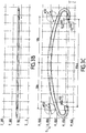
- the cross 300 has several zones, which differ in their conformation in cross section.
- FIG. 3G This shows five successive zones, denoted 301R to 305R.
- the zone 301R here has a constant cross section, whose shape is given by the sectional view AA of the 3D figure . It is a form of oval look, whose large dimension is horizontal. The ratio between the large dimension and the small dimension is about 2.
- zone 303R here has a cross-section that is also constant, the shape of which is given by the sectional view BB of FIG. figure 3E .
- This form can be described as the shape of the 3D figure , provided with a fold on itself of the tubular structure. This fold is directed inward, radially, along the long axis of the oval, the side of the vehicle chassis.
- the 302R zone is an evolutionary transition zone, in which the shape of the 3D figure to that of the figure 3E .
- the fold comprises a right cell of gradually increasing depth towards the ends of the tubular structure.
- the evolution of the depth of the fold is illustrated by the long dashed line 3021.
- zone 304R is planned here, in which the form of the figure 3E to a basic shape, which may be the oval shape of the 3D figure .
- a short straight end of zone 304R which has a cylindrical surface shape whose cross-section is that of the 3D figure .
- an attachment zone 305R where the tube is crushed horizontally, on the frame side, as illustrated on the section of the figure 3F .
- This zone comprises for example a fixing eyelet 306R.
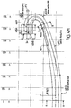
- the cross 400 has several zones, which differ in their conformation in cross section.
- the zone 401R here has a constant cross section, whose shape is given by the sectional view AA of the figure 4D . It is a form of oval shape, or rhombus with rounded corners, very flat, whose large dimension is horizontal. The ratio between the large dimension and the small dimension is here about 6.
- the zone 403R here has a cross section also constant, the shape of which is given by the sectional view BB of the figure 4E .
- This form can be described as an oval shape, strongly folded on itself. Indeed, the external profile (envelope) of the figure 4E superimposes itself well on the shape of the figure 4F .
- the envelope of this oval shape is much less flattened than the shape of the figure 4D .
- the fold is directed inward, radially, along the long axis of the oval, the side of the frame. It extends widely inside the oval, almost three-quarters.
- the internal space between the fold and the outer contour is substantially constant. We also note that this internal space is of a size close to that of the small dimension of the shape of the figure 4D .
- the 402R zone is an evolutionary transition zone, in which the shape of the figure 4D to that of the figure 4E .
- the fold comprises a right cell of gradually increasing depth towards the ends of the tubular structure.
- the evolution of the depth of the fold is illustrated by the long dashed line 4021.
- the decrease of the flattening of the oval envelope shape is visible in 4022R on the Figure 4B .
- the Figure 4H also shows a slight recess 4025, at the end of the evolutionary zone, in the vicinity of the right of the fastener.
- an attachment zone 405R where the tube is crushed horizontally, on the frame side, as shown in the cross-section of FIG. figure 4G .
- This zone comprises for example a fixing eyelet 406R.
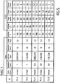
- the symbols E335D / 510 and E26 / 420 indicate two grades of steel. The number after the slash indicates the yield point.
- brackets fold backwards overflowing relative to the right-of-way of the vehicle chassis.
- the four columns on the right indicate respectively: - in "W40mm” energy absorbed by the crossbar, for a travel less than 40mm, in Joules (J). It is desired a value of at least 140 joules. - in “Fmax” the peak value of the contact force, unfiltered, with the impactor, in decaNewton (daN). It is desired not to exceed about 700 daN, on a stroke at least equal to 40 mm. - in "Decel” the deceleration experienced by the impactor, measured at the upper end of the tibia. The unit of measure is the Earth acceleration (g). It is expected to remain below the 200 g limit, which will become 150 g from 1 September 2010. - in "Shear.” the maximum dynamic displacement in shear of the knee. It is planned to stay below the limit of 6 mm.
- the folding occurs substantially without modification of the envelope of the cross section as it is in the central portion of the tubular structure.
- the folding takes place on a cross section whose ratio between the maximum dimension and the minimum dimension decreases when going towards the ends.
- the embodiments described are not limiting, nor on the dimensions of the base tube, nor in its conformations.
- the cross is not necessarily completely symmetrical.
- five zones are defined in the sleepers described in detail. But the number of zones can be lower, or higher.
- the desired conformation of the tube can be achieved by pressing and / or cold-stamping, with the required number of passes.
- Examples of given materials are not limiting. Other grades of steel, or aluminum compositions, may be suitable.
- the invention has been described for a lower crossbar front bumper. With suitable adaptations, it can be applied to other parts of the vehicle, such as a high cross member, or intermediate, or as part of a rear bumper, or side protection, where shocks can occur at significant speed with fragile bodies.
- the tubular structure is arched, its convexity facing forward.
- a straight structure (excluding the butts) is also possible.
- the crossbar may also have a curved structure in the space.
Landscapes
- Engineering & Computer Science (AREA)
- Mechanical Engineering (AREA)
- Body Structure For Vehicles (AREA)
- Vibration Dampers (AREA)
Priority Applications (1)
| Application Number | Priority Date | Filing Date | Title |
|---|---|---|---|
| PL06726077T PL1863676T3 (pl) | 2005-03-30 | 2006-03-13 | Poprzeczne zderzaki dla pojazdów silnikowych, do ochrony pieszych |
Applications Claiming Priority (2)
| Application Number | Priority Date | Filing Date | Title |
|---|---|---|---|
| FR0503090A FR2883830B1 (fr) | 2005-03-30 | 2005-03-30 | Traverse de pare-chocs pour vehicules automobiles, preservant les pietons |
| PCT/FR2006/000548 WO2006103326A1 (fr) | 2005-03-30 | 2006-03-13 | Traverse de pare-chocs pour vehicules automobiles, preservant les pietons. |
Publications (2)
| Publication Number | Publication Date |
|---|---|
| EP1863676A1 EP1863676A1 (fr) | 2007-12-12 |
| EP1863676B1 true EP1863676B1 (fr) | 2018-11-07 |
Family
ID=35285505
Family Applications (1)
| Application Number | Title | Priority Date | Filing Date |
|---|---|---|---|
| EP06726077.8A Expired - Lifetime EP1863676B1 (fr) | 2005-03-30 | 2006-03-13 | Traverse de pare-chocs pour vehicules automobiles, preservant les pietons |
Country Status (4)
| Country | Link |
|---|---|
| EP (1) | EP1863676B1 (pl) |
| FR (1) | FR2883830B1 (pl) |
| PL (1) | PL1863676T3 (pl) |
| WO (1) | WO2006103326A1 (pl) |
Families Citing this family (4)
| Publication number | Priority date | Publication date | Assignee | Title |
|---|---|---|---|---|
| FR2933051B1 (fr) * | 2008-06-27 | 2018-03-09 | Renault Sas | Dispositif d'absorption de choc de compacite accrue |
| DE102010006977A1 (de) * | 2010-02-05 | 2011-08-11 | GM Global Technology Operations LLC, ( n. d. Ges. d. Staates Delaware ), Mich. | Kraftfahrzeug-Vorderbau |
| DE102010006976A1 (de) | 2010-02-05 | 2011-08-11 | GM Global Technology Operations LLC, ( n. d. Ges. d. Staates Delaware ), Mich. | Kraftfahrzeug-Vorderbau |
| DE102010006975A1 (de) | 2010-02-05 | 2011-08-11 | GM Global Technology Operations LLC, ( n. d. Ges. d. Staates Delaware ), Mich. | Kraftfahrzeug-Vorderbau |
Family Cites Families (10)
| Publication number | Priority date | Publication date | Assignee | Title |
|---|---|---|---|---|
| NO173538C (no) * | 1991-09-06 | 1993-12-29 | Norsk Hydro As | Konstruksjonsbjelke og fremgangsmaate ved produksjon av den samme |
| GB2334008A (en) * | 1997-12-20 | 1999-08-11 | Rover Group | Vehicle subframes |
| DE19849358C2 (de) * | 1998-10-27 | 2000-10-12 | Benteler Werke Ag | Stoßfänger für Kraftfahrzeuge |
| NO990503D0 (no) * | 1999-02-03 | 1999-02-03 | Norsk Hydro As | St°tfanger og fremgangsmÕte ved fremstilling av samme |
| EP1065108B1 (en) * | 1999-06-28 | 2004-04-21 | Mazda Motor Corporation | Structure of the front of a vehicle body |
| FR2800695B1 (fr) | 1999-11-08 | 2001-12-07 | Renault | Vehicule, notamment de tourisme, a structure d'encaissement de choc anti-chevauchement |
| SE516762C2 (sv) * | 1999-12-14 | 2002-02-26 | Accra Teknik Ab | Stötfångarbalk och förfarande vid tillverkning av densamma |
| US6540276B2 (en) * | 2000-11-09 | 2003-04-01 | Aisin Seiki Kabushiki Kaisha | Bumper reinforcement structure |
| FR2824523B1 (fr) | 2001-05-11 | 2003-10-10 | Peugeot Citroen Automobiles Sa | Structure de vehicule automobile a compotement ameliore au choc |
| US20040094975A1 (en) * | 2002-11-14 | 2004-05-20 | Stephen Shuler | Hybrid bumper system |
-
2005
- 2005-03-30 FR FR0503090A patent/FR2883830B1/fr not_active Expired - Lifetime
-
2006
- 2006-03-13 WO PCT/FR2006/000548 patent/WO2006103326A1/fr not_active Ceased
- 2006-03-13 PL PL06726077T patent/PL1863676T3/pl unknown
- 2006-03-13 EP EP06726077.8A patent/EP1863676B1/fr not_active Expired - Lifetime
Non-Patent Citations (1)
| Title |
|---|
| None * |
Also Published As
| Publication number | Publication date |
|---|---|
| EP1863676A1 (fr) | 2007-12-12 |
| FR2883830B1 (fr) | 2007-08-24 |
| FR2883830A1 (fr) | 2006-10-06 |
| WO2006103326A1 (fr) | 2006-10-05 |
| PL1863676T3 (pl) | 2019-05-31 |
Similar Documents
| Publication | Publication Date | Title |
|---|---|---|
| EP2233368B1 (fr) | Ensemble avant de véhicule automobile comprenant un bouclier pare-chocs avant | |
| EP2322386B1 (fr) | Ensemble avant de véhicule automobile comprenant un bouclier pare-chocs avant portant des moyens de fixation d'au moins un équipement auxiliaire du véhicule automobile | |
| EP2338743B1 (fr) | Ensemble pare-chocs pour véhicule automobile, partie d'extrémité de véhicule automobile comprenant un tel ensemble et véhicule automobile | |
| EP2325057A1 (fr) | Bouclier pare-chocs pour véhicule automobile | |
| CH631770A5 (fr) | Dispositif de securite pour la circulation routiere. | |
| FR2829734A1 (fr) | Poutre de pare-chocs pour vehicule comprenantune traversee et deux absorbeurs de chocs | |
| FR3050705A1 (fr) | Vehicule avec renforts lateraux en bas de porte | |
| EP2135778B1 (fr) | Pare-chocs arrière pour véhicule automobile utilitaire | |
| EP1422110A2 (fr) | Pare-chocs de véhicule automobile comportant un bloc compressible à section transversale croissante | |
| WO2006103326A1 (fr) | Traverse de pare-chocs pour vehicules automobiles, preservant les pietons. | |
| EP3820743A1 (fr) | Guide d'air pour vehicule automobile realise d'une piece en materiau polymere expanse et comportant des zones d'absorption de choc | |
| WO2022175610A1 (fr) | Montage de traverse avant pour crash test « small overlap » | |
| EP2032419B1 (fr) | Piece de structure obtenue par raboutage pour vehicule automobile | |
| FR3066163B1 (fr) | Piece d’extension ameliorant la resistance d’une traverse de pare-chocs en cas de chocs de faible amplitude | |
| FR3041580A1 (fr) | Structure de vehicule comportant un dispositif de renfort et vehicule comportant une telle structure | |
| WO2008061824A1 (fr) | Ensemble d'absorption de chocs pour vehicule automobile et face avant correspondante | |
| EP2325056B1 (fr) | Bouclier pare-chocs pour véhicule automobile | |
| EP2441626B1 (fr) | Absorbeur d'énergie, notamment pour poutre de pare-chocs de véhicule automobile | |
| FR2810940A1 (fr) | Bloc avant comprenant des elements d'absorption d'energie de choc et vehicule automobile correspondant | |
| EP2112028B1 (fr) | Absorbeur pour véhicule automobile | |
| EP4426588B1 (fr) | Ensemble de protection avant pour véhicule automobile | |
| FR3055118A1 (fr) | Absorbeur de choc arriere de vehicule automobile | |
| EP2325070A1 (fr) | Ensemble avant de véhicule automobile comprenant un bouclier pare-chocs avant pourvu d'une poutre permettant la fixation d'au moins un équipement auxiliaire du véhicule automobile | |
| FR3072070B1 (fr) | Partie arriere d’un vehicule adaptee pour amortir un choc arriere qui comporte un puits dans lequel est positionnee une roue de secours | |
| WO2025202549A1 (fr) | Structure avant de véhicule automobile et véhicule automobile comportant une telle structure avant |
Legal Events
| Date | Code | Title | Description |
|---|---|---|---|
| PUAI | Public reference made under article 153(3) epc to a published international application that has entered the european phase |
Free format text: ORIGINAL CODE: 0009012 |
|
| 17P | Request for examination filed |
Effective date: 20070908 |
|
| AK | Designated contracting states |
Kind code of ref document: A1 Designated state(s): CZ DE FR PL |
|
| 17Q | First examination report despatched |
Effective date: 20080402 |
|
| RIN1 | Information on inventor provided before grant (corrected) |
Inventor name: DERCHU, THIERRY Inventor name: CHRETIEN, JEAN-MICHEL Inventor name: COLMONT, JEAN-LOUIS Inventor name: COCU, ARNAUD |
|
| DAX | Request for extension of the european patent (deleted) | ||
| RBV | Designated contracting states (corrected) |
Designated state(s): CZ DE FR PL |
|
| RAP1 | Party data changed (applicant data changed or rights of an application transferred) |
Owner name: ARCELORMITTAL TUBULAR PRODUCTS VITRY |
|
| GRAP | Despatch of communication of intention to grant a patent |
Free format text: ORIGINAL CODE: EPIDOSNIGR1 |
|
| INTG | Intention to grant announced |
Effective date: 20180504 |
|
| GRAS | Grant fee paid |
Free format text: ORIGINAL CODE: EPIDOSNIGR3 |
|
| GRAJ | Information related to disapproval of communication of intention to grant by the applicant or resumption of examination proceedings by the epo deleted |
Free format text: ORIGINAL CODE: EPIDOSDIGR1 |
|
| GRAL | Information related to payment of fee for publishing/printing deleted |
Free format text: ORIGINAL CODE: EPIDOSDIGR3 |
|
| GRAR | Information related to intention to grant a patent recorded |
Free format text: ORIGINAL CODE: EPIDOSNIGR71 |
|
| GRAA | (expected) grant |
Free format text: ORIGINAL CODE: 0009210 |
|
| INTC | Intention to grant announced (deleted) | ||
| INTG | Intention to grant announced |
Effective date: 20180924 |
|
| AK | Designated contracting states |
Kind code of ref document: B1 Designated state(s): CZ DE FR PL |
|
| REG | Reference to a national code |
Ref country code: DE Ref legal event code: R096 Ref document number: 602006056758 Country of ref document: DE |
|
| REG | Reference to a national code |
Ref country code: DE Ref legal event code: R097 Ref document number: 602006056758 Country of ref document: DE |
|
| PLBE | No opposition filed within time limit |
Free format text: ORIGINAL CODE: 0009261 |
|
| STAA | Information on the status of an ep patent application or granted ep patent |
Free format text: STATUS: NO OPPOSITION FILED WITHIN TIME LIMIT |
|
| 26N | No opposition filed |
Effective date: 20190808 |
|
| P01 | Opt-out of the competence of the unified patent court (upc) registered |
Effective date: 20230523 |
|
| PGFP | Annual fee paid to national office [announced via postgrant information from national office to epo] |
Ref country code: DE Payment date: 20250218 Year of fee payment: 20 |
|
| PGFP | Annual fee paid to national office [announced via postgrant information from national office to epo] |
Ref country code: FR Payment date: 20250218 Year of fee payment: 20 Ref country code: PL Payment date: 20250221 Year of fee payment: 20 Ref country code: CZ Payment date: 20250225 Year of fee payment: 20 |
|
| REG | Reference to a national code |
Ref country code: DE Ref legal event code: R071 Ref document number: 602006056758 Country of ref document: DE |
|
| PG25 | Lapsed in a contracting state [announced via postgrant information from national office to epo] |
Ref country code: CZ Free format text: LAPSE BECAUSE OF EXPIRATION OF PROTECTION Effective date: 20260313 |