EP1863293A2 - Bildverarbeitungsvorrichtung, Bildverarbeitungsverfahren und Bildverarbeitungsprogramm - Google Patents
Bildverarbeitungsvorrichtung, Bildverarbeitungsverfahren und Bildverarbeitungsprogramm Download PDFInfo
- Publication number
- EP1863293A2 EP1863293A2 EP07251117A EP07251117A EP1863293A2 EP 1863293 A2 EP1863293 A2 EP 1863293A2 EP 07251117 A EP07251117 A EP 07251117A EP 07251117 A EP07251117 A EP 07251117A EP 1863293 A2 EP1863293 A2 EP 1863293A2
- Authority
- EP
- European Patent Office
- Prior art keywords
- vector
- image data
- format
- pixel
- pixels
- Prior art date
- Legal status (The legal status is an assumption and is not a legal conclusion. Google has not performed a legal analysis and makes no representation as to the accuracy of the status listed.)
- Withdrawn
Links
Images


Classifications
-
- H—ELECTRICITY
- H04—ELECTRIC COMMUNICATION TECHNIQUE
- H04N—PICTORIAL COMMUNICATION, e.g. TELEVISION
- H04N19/00—Methods or arrangements for coding, decoding, compressing or decompressing digital video signals
- H04N19/85—Methods or arrangements for coding, decoding, compressing or decompressing digital video signals using pre-processing or post-processing specially adapted for video compression
- H04N19/86—Methods or arrangements for coding, decoding, compressing or decompressing digital video signals using pre-processing or post-processing specially adapted for video compression involving reduction of coding artifacts, e.g. of blockiness
-
- H—ELECTRICITY
- H04—ELECTRIC COMMUNICATION TECHNIQUE
- H04N—PICTORIAL COMMUNICATION, e.g. TELEVISION
- H04N19/00—Methods or arrangements for coding, decoding, compressing or decompressing digital video signals
- H04N19/42—Methods or arrangements for coding, decoding, compressing or decompressing digital video signals characterised by implementation details or hardware specially adapted for video compression or decompression, e.g. dedicated software implementation
- H04N19/436—Methods or arrangements for coding, decoding, compressing or decompressing digital video signals characterised by implementation details or hardware specially adapted for video compression or decompression, e.g. dedicated software implementation using parallelised computational arrangements
-
- H—ELECTRICITY
- H04—ELECTRIC COMMUNICATION TECHNIQUE
- H04N—PICTORIAL COMMUNICATION, e.g. TELEVISION
- H04N19/00—Methods or arrangements for coding, decoding, compressing or decompressing digital video signals
- H04N19/60—Methods or arrangements for coding, decoding, compressing or decompressing digital video signals using transform coding
Definitions
- This invention relates to an image processing apparatus, image processing method and image processing program.
- a high compression rate has been realized by combining a process of reducing the redundancy in the time direction between adjacent frames and a process of reducing the redundancy in the spatial direction in a single frame.
- an image is divided into pixel blocks with adequate size (for example, the four pixels in width and the four pixels in height) and redundant components of the blocks are eliminated by subjecting the blocks to a DCT (discrete cosine transform) process for each block unit in many cases.
- DCT discrete cosine transform
- a process called a deblocking filtering process which suppresses block noises by making a correction to make smooth discontinuous pixels near the block boundary is added.
- the deblocking filtering process is relatively simple, but the processing amount required for the deblocking filtering process is extremely large and it accounts for 50% of the total processing amount of the decoding process in some cases. Therefore, in JP. A 2004-180248 (KOKAI) or the like, the technique for reducing the processing amount of the deblocking filter and making the operation speed high by determining whether the coding distortion eliminating process is required or not and operating the deblocking filter only when the above eliminating process is required is proposed.
- the progress of a recent GPU is significant and the GPU comes to have both of high programmability and parallel arithmetic operation ability. Therefore, the GPUs tend to be mounted not only on computers such as PCs but also on household electrical appliances, mobile instruments or game machines. Further, an attempt to utilize the GPU for general applications other than the graphics by making use of the high programmability thereof is actively made and the attempt extends to a field of coding and decoding of moving pictures.
- the general-purpose parallel vector processor such as the GPU is not considered as a platform which realizes the deblocking filter. Therefore, the deblocking filter cannot be operated at high speed by making full use of the ability of the general-purpose parallel vector processor such as the GPU.
- An image processing apparatus comprises: an overlapping unit configured to overlap a plurality of scalar format images arranged in at least one of a horizontal direction and a vertical direction and convert them into vector format image data; and an image processing unit configured to perform a deblocking filter processing for the vector image data.
- the invention is not limited to the apparatus, and may be realized by the method and computer readable program.
- the point of this invention is as follows.
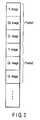
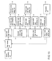
- an image processing apparatus includes a central processing unit 1, main memory unit 2, input scalar image memory unit 3, horizontal scalar pixel overlapping unit 4, horizontal vector image memory unit 5, horizontal vector image processing unit 6, vertical scalar pixel overlapping unit 7, vertical vector image memory unit 8, vertical vector image processing unit 9, vertical vector image development unit 10, output scalar image memory unit 11 and presentation unit 12.
- FIG. 1 shows the flow of data in addition to the connection relation between the blocks. The functions of the respective blocks are explained below.
- the central processing unit 1 controls the operations of the respective blocks and data transfer between the blocks.
- the main memory unit 2 holds programs to control the operations of the respective blocks, moving picture data and the like.
- the input scalar image memory unit 3 stores scalar format input image data.
- the horizontal scalar pixel overlapping unit 4 reads out scalar format image data held in the input scalar image memory unit 3, overlaps a plurality of scalar format pixels arranged in a horizontal direction and converts the overlapped data into vector format image data.
- the horizontal vector image memory unit 5 stores vector format image data output from the horizontal scalar pixel overlapping unit 4.
- the horizontal vector image processing unit 6 subjects the vector format image data held in the horizontal vector image memory unit 5 to a deblocking filtering process.
- the vertical scalar pixel overlapping unit 7 reads out vector format image data held in the horizontal vector image memory unit 5, overlaps the elements of a plurality of vector format pixels arranged in a vertical direction and converts the overlapped data into different vector format image data.
- the vertical vector image memory unit 8 stores vector format image data output from the vertical scalar pixel overlapping unit 7.
- the vertical vector image processing unit 9 subjects the vector format image data held in the vertical vector image memory unit 8 to a deblocking filtering process.
- the vertical vector image development unit 10 reads out vector format image data held in the vertical vector image memory unit 8, develops the elements of the respective vector format pixels in the vertical direction and converts the developed data into scalar format image data.
- the output scalar image memory unit 11 stores scalar format image data output from the vertical vector image development unit 10.
- the presentation unit 12 has a display device such as a liquid crystal display device and presents image data held in the output scalar image memory unit 11.
- the respective memory units of the main memory unit 2, input scalar image memory unit 3, horizontal vector image memory unit 5, vertical vector image memory unit 8 and output scalar image memory unit 11 are represented by different constituents, but they can be collectively configured on a single memory or separately configured on a plurality of different memories.
- the central processing unit 1 controls the operations of the respective blocks and data transfer between the blocks.
- the main memory unit 2 stores programs used to control the operations of the respective blocks, moving picture data and image data transferred from the output scalar image memory unit 11 and subjected to a deblocking filtering process.
- moving picture data is obtained by arranging image data in the respective color components of one frame of a moving picture.
- the following explanation is made on the assumption that the above moving picture data is previously stored in the main memory unit 2.
- the input scalar image memory unit 3 stores only image data of a specific color component of a present frame in the moving picture data held in the main memory unit 2.
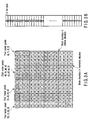
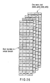
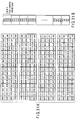
- FIG. 3A shows the pixel array in the input scalar image memory unit 3 and FIG. 3B shows an example of the arrangement order of the pixels on the memory.
- FIG. 3B shows an example of the arrangement order of the pixels on the memory.
- an 8-bit scalar value is assigned to respective pixels and the respective pixels is arranged in a raster order in image data of a specific color component (refer to FIG. 3B).
- FIGS. 3A and 3B shows the operations of the respective blocks performed when image data of FIGS. 3A and 3B are given.
- the horizontal scalar pixel overlapping unit 4 reads out image data held in the input scalar image memory unit 3 as shown in FIG. 3A, overlaps a plurality of scalar format pixels successively arranged in the horizontal direction and converts the overlapped pixels into one pixel vector so that each pixel corresponds an element of the vector.
- vector format image data as shown in FIG. 4A is obtained.
- an adequate conversion method is selected based on conditions of the width of the pixel block, the format of the scalar format pixel before conversion, the format of the vector format pixel after conversion, a reference pixel of the deblocking filter with respect to the pixel block boundary in the horizontal direction and the like.
- the width of the pixel block is four pixels as shown in FIG. 3A and the scalar format pixel before conversion is represented by an 8-bit integer format as shown in FIG. 3B.
- the horizontal scalar pixel overlapping unit 4 overlaps four scalar format pixels arranged in the horizontal direction in the pixel block shown in FIG. 3A to convert them into one vector format pixel having four elements as shown in FIGS. 4A to 4C. The detail operation will be explained below.
- the size of the pixel block has the width of one pixel, the four pixels in height and the depth (the number of elements of the vector pixel) of four pixels in the vector format image data after conversion and pixel block boundaries in the horizontal direction are set between the respective pixels arranged in the horizontal direction.
- FIG. 4B is a diagram showing the vector format pixels for each element in a plane format.
- the vector format pixel after conversion has four elements and each element is represented by an 8-bit integer format.
- the horizontal scalar pixel overlapping unit 4 After conversion from the scalar format to the vector format, the horizontal scalar pixel overlapping unit 4 outputs the obtained vector format image data to the horizontal vector image memory unit 5.
- the horizontal vector image memory unit 5 stores the vector format image data (FIGS. 4A to 4C) output from the horizontal scalar pixel overlapping unit 4.
- the horizontal vector image processing unit 6 subjects the pixel block boundary in the horizontal direction of the vector format image data (FIGS. 4A to 4C) held in the horizontal vector image memory unit 5 to the deblocking filtering process.
- the operation of the deblocking filter is performed by deriving a weighted average of pixels lying near a plurality of pixels near the pixel block boundary for the plurality of pixels.
- the pixels and weights used for the weighted average are adaptively determined according to various conditions in many cases.
- the operation of the weighted average is supposed as follows. As shown in FIG. 5, eight pixels (p3 to p0 and q0 to q3) arranged on the right and left sides of the pixel block boundary in the horizontal direction are used as a reference pixel of the deblocking filter with respect to the boundary.
- filter () is a function used to calculate the weighted average of scalar format pixel values given to an argument. Since setting of the weights used for the weighted average is not directly related to the contents of this invention, the explanation thereof will be omitted.
- a parallel arithmetic unit in the processor determines one of the eight scalar format pixels which is input and must process a complicated condition branch in order to switch calculations for the weighted average according to the result of determination.
- hatched pixels indicate that the filtering process is performed by use of the hatched pixels to derive values of the hatched pixels. For example, it is indicated in FIG.
- the pixel p3' is obtained by performing the filtering process by use of the pixel p3 and it is indicated in FIG. 6B that the pixel p2' is obtained by performing the filtering process by use of the pixels p3, p2, p1, p0, q0. Since this applies to the other cases, the explanation thereof will be omitted.
- the scalar format pixels are converted into the vector format pixel by the preceding-stage horizontal scalar pixel overlapping unit 4, it is only required to perform the arithmetic operation for two vector format pixels as shown in FIG. 7A. Therefore, as shown in FIG. 7B, the parallel arithmetic unit in the processor is only required to determine one of the two vector format pixels and the number of condition branches can be reduced.
- the vector format pixels (p3, p2, p1, p0), (q0, q1, q2, q3), (p3', p2', p1' , p0') and (q0', q1', q2', q3') are respectively represented by p, q, p' and q'.
- filter () is a function used to calculate the weighted average with reference to vector format pixel values given to an argument.
- the arithmetic operation of the deblocking filter When the arithmetic operation of the deblocking filter is performed, it is necessary to pay attention to the process dependency of the arithmetic operation.
- the result of filtering for the boundary between the pixel block of the column 1 and the pixel block of the column 2 depends on the pixel value of the column 1, but the pixel value of the column 1 depends on the result of filtering for the boundary between the column 1 and the adjacent column 0 on the left side. Therefore, the correct result cannot be obtained if the filtering process for the boundary between the column 0 and the column 1 of FIG. 8A is not completed before filtering the boundary between the column 1 and the column 2 of FIG. 8B. Likewise, the correct result cannot be obtained if the filtering process for the boundary between the column 1 and the column 2 of FIG. 8B is not completed before filtering the boundary between the column 2 and the column 3 of FIG. 8C.
- the filtering process for the boundary between the column 0 and the column 1 is performed with reference to colored pixel blocks of FIG. 8A and the filtering process for the boundary between the column 1 and the column 2 is performed with reference to colored pixel blocks of FIG. 8B after the above filtering process is completed. Then, after all of the above filtering processes are completed, the filtering process for the boundary between the column 2 and the column 3 is performed with reference to colored pixel blocks of FIG. 8C.
- the horizontal vector image processing unit 6 When calculation for the weighted average of all of the pixels lying near the pixel block boundary in the horizontal direction is completed, the horizontal vector image processing unit 6 outputs vector format image data subjected to the deblocking filtering process to the horizontal vector image memory unit 5.
- the vertical scalar pixel overlapping unit 7 reads out vector format image data (FIGS. 4A to 4C) held in the horizontal vector image memory unit 5 and overlaps elements of a plurality of vector format pixels arranged in the vertical direction to convert them into different vector format image data (FIGS. 9 to 10B) which will be described in detail later.
- an adequate conversion method is selected according to conditions of the height of the pixel block, the format of the vector format pixel before conversion, the format of the vector format pixel after conversion, a reference pixel of the deblocking filter with respect to the pixel block boundary in the vertical direction and the like.
- the height of the pixel block is four pixels.
- the vector format pixel before conversion is configured by four elements and each element is represented by an 8-bit integer format.
- the vertical scalar pixel overlapping unit 7 overlaps vector elements corresponding to the four vector format pixels arranged in the vertical direction in the pixel block in FIG. 4A and converts them into different vector format pixels as shown in FIGS. 9 to 10B.
- the concrete operation is as follows.
- fourth elements f0, f1, f2, f3 in four vector format pixels (c0, d0, e0, f0), (c1, d1, e1, f1), (c2, d2, e2, f2) and (c3, d3, e3, f3) in FIG. 4A are converted into one vector format pixel (f0, f1, f2, f3) surrounded by broken lines in FIG. 9. Likewise, the other elements are converted.
- the first element is converted into a pixel (c0, c1, c2, c3)
- the second element is converted into a pixel (dO, d1, d2, d3)
- the third element is converted into a pixel (e0, e1, e2, e3).
- the size of the pixel block has the four pixels in width, the height of one pixel and the depth (the number of elements of the vector pixel) of four pixels and pixel block boundaries in the vertical direction are set between the respective pixels arranged in the vertical direction.
- FIG. 10A shows the vector format pixels for each element in a plane format.
- the vector format pixel after conversion is configured by four elements and each element is represented by an 8-bit integer format.
- the vertical scalar pixel overlapping unit 7 outputs the overlapped vector format image data to the vertical vector image memory unit 8.
- the vertical vector image memory unit 8 holds vector format image data (FIGS. 9 to 10B) output from the vertical scalar pixel overlapping unit 7.
- the vertical vector image processing unit 9 subjects the pixel block boundary in the vertical direction of the vector format image data (FIGS. 9 to 10B) held in the vertical vector image memory unit 8 to the deblocking filtering process.
- the deblocking filtering process As shown in FIG. 11, eight pixels (p3 to p0 and q0 to q3) arranged on the upper and lower sides of the boundary in the vertical direction of the pixel block are used as a reference pixel of the deblocking filter with respect to the boundary.
- the processing contents of the deblocking filter with respect to the pixel block boundary in the vertical direction correspond to values obtained by regarding the pixels p3 to p0, q0 to q3, p3' to p1' and q0' to q3' in the processing contents of the horizontal vector image processing unit 6 as values of pixels arranged in the vertical direction as shown in FIG. 11.
- the weighted average can be calculated simply by performing the arithmetic operation for the two vector format pixels. Further, the parallel arithmetic unit in the processor is only required to determine one of the two vector format pixels and the number of condition branches can be suppressed to 2.
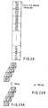
- FIGS. 12A to 12C The process dependency of the operation of the deblocking filter with respect to the pixel block boundary in the vertical direction is shown in FIGS. 12A to 12C.
- the boundary between the pixels of the row 0 and row 1 of FIG. 12A is subjected to filtering with reference to the above pixels.
- the boundary between pixels of the row 1 and row 2 of FIG. 12B is subjected to filtering with reference to the above pixels.
- the boundary between pixels of the row 2 and row 3 of FIG. 12C is subjected to filtering with reference to the above pixels.
- the vertical vector image processing unit 9 outputs the vector format image data subjected to the deblocking filtering process to the vertical vector image memory unit 8.
- the vertical vector image development unit 10 reads out vector format image data (FIGS. 9 to 10B) held in the vertical vector image memory unit 8 and develops the elements of the vector format pixels in the vertical direction to convert the image data into scalar format image data (FIGS. 3A and 3B).
- an adequate conversion method is selected according to conditions of the height of the pixel block, the format of the vector format pixel before conversion and the format of the scalar format pixel after conversion and the like.
- the height of the pixel block is four pixels.
- the scalar format pixel before conversion is represented by an 8-bit integer format.
- the scalar format pixel after conversion is represented by an 8-bit integer format.
- the vertical vector image development unit 10 converts vector format pixels into scalar format pixels as shown in FIG. 3A by developing the elements of the vector format pixels shown in FIG. 9 in the vertical direction.
- one vector format pixel (f0, f1, f2, f3) surrounded by broken lines in FIG. 9 is converted into four scalar format pixels f0, f1, f2, f3 surrounded by broken lines in FIG. 3A.
- the vertical vector image development unit 10 outputs the developed scalar format image data to the output scalar image memory unit 11.
- the output scalar image memory unit 11 stores the scalar format image data output from the vertical vector image development unit 10.
- the presentation unit 12 presents the image data held in the output scalar image memory unit 11 to the user.
- a plurality of pixels near the pixel block boundary are overlapped and converted into a vector format.
- the operation speed of the deblocking filter can be made high by fully utilizing the arithmetic operation ability of the general-purpose parallel vector processor such as the GPU.
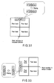
- a second embodiment is different from the first embodiment in that a horizontal vector pixel array sorting unit 13 and vertical vector pixel array sorting unit 14 are additionally provided in the image processing apparatus according to the first embodiment. Therefore, portions which are the same as those of FIG. 1 are denoted by the same reference symbols and the repetitive explanation for the same portions will be omitted.
- the horizontal vector image processing unit 6 in the first embodiment first subjects the pixels of the pixel blocks of the column 0 and the pixel blocks of the column 1 to the parallel process by use of the deblocking filter (FIG. 8A) and then the pixels of the column 1 and column 2 are subjected to the parallel process after the former process is completed (FIG. 8B). Then, after the whole process is completed, the pixels of the column 2 and column 3 are subjected to the parallel process (FIG. 8C).
- the horizontal vector image processing unit 6 uses an area of two columns of the pixel blocks as the processing unit in each parallel process. Therefore, for example, in a case where the resolution of an input scalar image (FIGS. 3A and 3B) is set to the width of 1920 pixels and the height of 1080 pixels, the unit of the parallel process is set to an extremely narrow area having the width of two pixels and the height of 1080 pixels.
- the parallel processor such as the GPU
- the operating rate of the parallel arithmetic unit and the hit rate of the cache are lowered and the original arithmetic operation ability cannot be fully utilized in many cases.
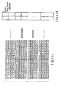
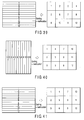
- vector format image data (FIGS. 4A to 4C) output from the horizontal scalar pixel overlapping unit 4 is read out by use of the horizontal vector pixel array sorting unit 13 and vector format pixel strings arranged on one column in the vertical direction are sorted on a plurality of columns (refer to FIG. 14).
- FIG. 15B is a diagram showing vector format pixels after substitution for each element in a plane format.
- the vertical vector image processing unit 9 in the first embodiment first subjects the pixels of the pixel block of the row 0 and the pixel block of the row 1 to the parallel process (FIG. 12A) and then subjects the pixels of the row 1 and row 2 to the parallel process (FIG. 12B) after the above process is completed. Then, after the above whole process is completed, the pixels of the row 2 and row 3 are subjected to the parallel process (FIG. 12C).
- the vertical vector image processing unit 9 uses an area of two rows of the pixel blocks as a processing unit in each parallel process. Therefore, for example, when the resolution of the input scalar image (FIGS. 3A and 3B) is set to the width of 1920 pixels and the height of 1080 pixels, the unit of the parallel process becomes an extremely narrow area with the width of 1920 pixels and the height of two pixels.
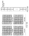
- the process of reading out vector format image data (FIGS. 9 to 10B) output from the vertical scalar pixel overlapping unit 7 and sorting vector format pixel strings arranged on one row in the horizontal direction into a plurality of rows is performed by the vertical vector pixel array sorting unit 14 (refer to FIG. 16).
- FIG. 17B is a diagram showing vector format pixels after substitution for each element in a plane format.
- the process of the deblocking filter with respect to the pixel block boundary in the vertical direction in the latter-stage vertical vector image processing unit 9 can be efficiently performed.
- the operating rate of the parallel vector processor such as the GPU and the hit rate of the cache can be enhanced and the operation speed of the deblocking filter can be made high by sorting the vector format pixels based on the process dependency of the deblocking filter and the memory access system of the parallel vector processor.
- the configuration of an image processing apparatus is the same as that of the first or second embodiment, and therefore, the drawing and repetitive explanation thereof are omitted.
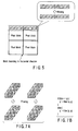
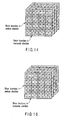
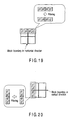
- the third embodiment as shown in FIG. 18, a case where the size of the pixel block of the scalar format image data stored in the input scalar image memory unit 3 is set to the width of two pixels and the height of two pixels is explained.
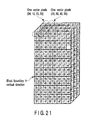
- the horizontal scalar pixel overlapping unit 4 is different from that of the first and second embodiments. It overlaps four scalar format pixels arranged on the right and left sides of the boundary between the pixel blocks in the horizontal direction in FIG. 18 and converts them into vector format pixels as shown in FIGS. 21 and 22.
- the concrete operation is as follows.
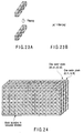
- FIG. 22 is a diagram showing the vector format pixels obtained after conversion for each element in a plane format.
- the arithmetic operation of the deblocking filter with respect to the pixel block in the horizontal direction in the horizontal vector image processing unit 6 can be attained simply by performing the arithmetic operation for one vector format pixel as shown in FIG. 23A. Further, as shown in FIG. 23B, it is not necessary for the parallel arithmetic unit in the processor to process the condition branch.
- vector format pixels (p1, p0, q0, q1) and (p1', p0', q0', q1') are respectively represented by pq and pq'.
- filter () is a function used to calculate the weighted average with reference to vector format pixel values given to an argument.
- the vertical scalar pixel overlapping unit 7 four scalar format pixels arranged on the upper and lower sides of the boundary between the pixel blocks in the vertical direction in FIG. 22 are overlapped and converted into different vector format pixels as shown in FIGS. 24 and 25.
- FIG. 22 For example, four scalar format pixels e0, e1, e2, e3 surrounded by broken lines in FIG. 22 are converted into one vector format pixel (e0, e1, e2, e3) surrounded by broken lines in FIG. 24. Likewise, four scalar format pixels f0, f1, f2, f3 surrounded by broken lines in FIG. 22 are converted into one vector format pixel (f0, f1, f2, f3) surrounded by broken lines in FIG. 24.
- FIG. 25 is a diagram showing the vector format pixels for each element in a plane format.
- the arithmetic operation ability of the general-purpose parallel vector processor such as the GPU can be fully utilized and the operation speed of the deblocking filter can be made high by overlapping a plurality of pixels near the pixel block boundary and converting them into a vector format based on the size of the pixel block.
- an image processing apparatus is the same as that of the first or second embodiment, and therefore, the drawing and repetitive explanation thereof are omitted.
- the embodiment a case where four elements of vector format pixels stored in the horizontal vector image memory unit 5 and vertical vector image memory unit 8 are represented by a 16-bit integer format is explained.
- the size of the pixel block, the reference pixel of the deblocking filter and the format of the scalar format pixel are the same as those in the first and second embodiments.
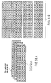
- the horizontal scalar pixel overlapping unit 4 overlaps eight scalar format pixels arranged on the right and left sides of the boundary between the pixel blocks in the horizontal direction in FIG. 3A and converts them into vector format pixels as shown in FIGS. 26 and 27.
- FIG. 3A eight scalar format pixels 80, 90, a0, b0, c0, d0, e0, f0 surrounded by broken lines in FIG. 3A are converted into one vector format pixel (80/90, a0/b0, c0/d0, e0/f0) surrounded by broken lines in FIG. 26.
- 80/90 indicates a 16-bit value having a value of the pixel 80 allocated to the upper eight bits and a value of the pixel 90 allocated to the lower eight bits.
- FIG. 28 is a diagram showing an example of the arrangement order of the pixels on the memory.
- the arithmetic operation of the deblocking filter with respect to the pixel block in the horizontal direction in the horizontal vector image processing unit 6 can be attained simply by performing the arithmetic operation for one vector format pixel. Further, as shown in FIG. 29B, it is not necessary for the parallel arithmetic unit in the processor to process the condition branch.
- vector format pixels (p3/p2, p1/p0, q0/q1, q2/q3) and (p3'/p2', p1' /p0', q0'/q1', q2'/q3') are respectively represented by pq and pq'.
- filter () is a function used to calculate the weighted average with reference to vector format pixel values given to an argument.
- the vertical scalar pixel overlapping unit 7 overlaps eight scalar format pixels arranged on the upper and lower sides of the boundary between the pixel blocks in the vertical direction in FIG. 27 to convert them into different vector format pixels as shown in FIGS. 30 and 31B as well as the above case.
- upper eight bits of the eight scalar format pixels surrounded by broken lines in FIG. 27 are converted into one vector format pixel (00/01, 02/03, 04/05, 06/07) surrounded by broken lines in FIG. 30.
- the arithmetic operation ability of the general-purpose parallel vector processor such as the GPU can be fully utilized and the operation speed of the deblocking filter can be made high by overlapping a plurality of pixels near the pixel block boundary and converting them into a vector format based on the format of the vector format pixel.
- the configuration of an image processing apparatus is the same as that of the first or second embodiment, and therefore, the drawing and repetitive explanation thereof are omitted.
- a case where four pixels (p1, p0, q0, q1) arranged on the right and left sides of the boundary between the pixel blocks in the horizontal direction as shown in FIG. 32 are used as a reference pixel of the deblocking filter with respect to the boundary is explained.
- FIG. 33 a case where four pixels arranged on the upper and lower sides of the boundary between the pixel blocks in the vertical direction are used as a reference pixel of the deblocking filter with respect to the boundary is explained.
- the horizontal scalar pixel overlapping unit 4 overlaps four scalar format pixels arranged on the right and left sides of the boundary between the pixel blocks in the horizontal direction in FIG. 3A and converts them into vector format pixels as shown in FIGS. 34A and 34B.
- FIG. 3A For example, four scalar format pixels 20, 30, 40, 50 surrounded by broken lines in FIG. 3A are converted into one vector format pixel (20, 30, 40, 50) surrounded by broken lines in FIG. 34A.
- the arithmetic operation of the deblocking filter with respect to the pixel block in the horizontal direction in the horizontal vector image processing unit 6 can be attained simply by performing the arithmetic operation for one vector format pixel as shown in FIG. 29A. Further, as shown in FIG. 29B, it is not necessary for the parallel arithmetic unit in the processor to process the condition branch.
- the vertical scalar pixel overlapping unit 7 overlaps four scalar format pixels arranged on the upper and lower sides of the boundary between the pixel blocks in the vertical direction in FIG. 34B and converts them into vector format pixels as shown in FIGS. 35A and 35B like the above case.
- the arithmetic operation ability of the general-purpose parallel vector processor such as the GPU can be fully utilized and the operation speed of the deblocking filter can be made high by overlapping a plurality of pixels near the pixel block boundary and converting them into a vector format based on the reference pixel of the deblocking filter.
- the configuration of an image processing apparatus is the same as that of the second embodiment, and therefore, the drawing and repetitive explanation thereof are omitted.
- the pixel substitution method by the horizontal vector pixel array sorting unit 13 and vertical vector pixel array sorting unit 14 is different from that in the second embodiment.
- the horizontal vector pixel array sorting unit 13 reads out vector format image data (FIGS. 4A to 4C) output from the horizontal scalar pixel overlapping unit 4 and sorts vector format pixel strings arranged on one column in the vertical direction into a plurality of columns.
- the horizontal vector pixel array sorting unit 13 performs the process of sorting vector format pixel strings arranged on one column in the vertical direction into a plurality of columns and then reallocating the plurality of columns.
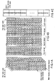
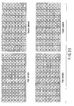
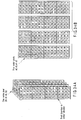
- vector format pixel strings (00, 10, 20, 30) to (0f, 1f, 2f, 3f) arranged on one column in the vertical direction on the left end portion surrounded by broken lines in FIG. 4B are sorted into vector format pixel strings arranged on four columns (four rows) and then allocated on the upper left portion of the pixel area of 8 rows and 8 columns in FIGS. 36A and 36B.
- vector format pixel strings (40, 50, 60, 70) to (4f, 5f, 6f, 7f) arranged on the second column from the left end in FIG. 4B are sorted into vector format pixel strings arranged on four columns (four rows) and then allocated on the upper right portion of the pixel area of 8 rows and 8 columns in FIGS. 36A and 36B.
- Vector format pixel strings (80, 90, a0, b0) to (8f, 9f, af, bf) arranged on the third column from the left end in FIG. 4B are sorted into vector format pixel strings arranged on four columns (four rows) and then allocated on the lower left portion of the pixel area of 8 rows and 8 columns in FIGS. 36A and 36B.
- vector format pixel strings (c0, d0, e0, f0) to (cf, df, ef, ff) arranged on the right end portion in FIG. 4B are sorted into vector format pixel strings arranged on four columns (four rows) and then allocated on the lower right portion of the pixel area of 8 rows and 8 columns in FIGS. 36A and 36B.
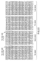
- FIG. 37 shows one example of the reallocation method in the embodiment.
- the horizontal vector pixel array sorting unit 13 sorts vector format pixel strings arranged on one column in the vertical direction into a plurality of columns and then sequentially allocates the plurality of columns in the horizontal direction. After the allocation process is performed by an adequate number of times, the process returns to the start point, then proceeds to the next row and is performed to sequentially allocate them in the horizontal direction by the same number of times.
- the turning position may be determined according to the memory access method of the parallel vector processor and the cache structure.
- the operating rate of the parallel arithmetic unit and the hit rate of the cache are enhanced, and therefore, the process of the deblocking filter with respect to the pixel block boundary in the horizontal direction in the latter-stage horizontal vector image processing unit 6 can be efficiently performed.
- the vertical vector pixel array sorting unit 14 of the embodiment performs the process of sorting vector format pixel strings arranged on one row in the horizontal direction into a plurality of rows and then reallocating the plurality of rows.
- the reallocation process is the feature of the vertical vector pixel array sorting unit 14 of the embodiment.
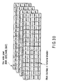
- vector format pixel strings (00, 01, 02, 03) to (f0, f1, f2, f3) arranged on one row in the horizontal direction on the upper end surrounded by broken lines in FIG. 10A are sorted into vector format pixel strings arranged on four rows (four columns) and then allocated on the upper left portion of the pixel area of 8 rows and 8 columns in FIGS. 38A and 38B.
- Vector format pixel strings (04, 05, 06, 07) to (f4, f5, f6, f7) arranged on the second row from the top in FIG. 10A are sorted into vector format pixel strings arranged on four rows (four columns) and then allocated on the upper right portion of the pixel area of 8 rows and 8 columns in FIGS. 38A and 38B.
- vector format pixel strings (08, 09, 0a, 0b) to (f8, f9, fa, fb) arranged on the third row from the top in FIG. 10A are sorted into vector format pixel strings arranged on four rows (four columns) and then allocated on the lower left portion of the pixel area of 8 rows and 8 columns in FIGS. 38A and 38B.
- vector format pixel strings (0c, 0d, 0e, 0f) to (fc, fd, fe, ff) arranged on the lower end portion in FIG. 10A are sorted into vector format pixel strings arranged on four rows (four columns) and then allocated on the lower right portion of the pixel area of 8 rows and 8 columns in FIGS. 38A and 38B.
- FIG. 39 shows an example of the reallocation method in the embodiment.
- the vertical vector pixel array sorting unit 14 sorts vector format pixel strings arranged on one row in the horizontal direction into a plurality of rows and then sequentially allocates the plurality of rows in the horizontal direction. After the allocation process is performed by an adequate number of times, the process returns to the start point, then proceeds to the next row and is performed to sequentially allocate them in the horizontal direction by the same number of times.
- the turning position may be determined according to the memory access system of the parallel vector processor and the cache structure.
- the operating rate of the parallel arithmetic unit and the hit rate of the cache are enhanced, and therefore, the process of the deblocking filter with respect to the pixel block boundary in the vertical direction in the latter-stage vertical vector image processing unit 9 can be efficiently performed.
- the operating rate of the parallel vector processor such as the GPU and the hit rate of the cache can be enhanced and the operation speed of the deblocking filter can be made high by sorting the vector format pixels based on the process dependency of the deblocking filter and the memory access system of the parallel vector processor.
- the configuration of an image processing apparatus is the same as that of the second embodiment, and therefore, the drawing and repetitive explanation thereof are omitted.
- the pixel substitution method by the horizontal vector pixel array sorting unit 13 and vertical vector pixel array sorting unit 14 is different from that in the second embodiment.
- the horizontal vector pixel array sorting unit 13 sorts vector format pixel strings arranged on one column in the vertical direction into a plurality of columns and then sequentially allocates the plurality of columns in the horizontal direction.
- the horizontal vector pixel array sorting unit 13 sorts vector format pixel strings arranged on one column in the vertical direction into a plurality of columns and then sequentially allocates the plurality of columns in the vertical direction. After the allocation process is performed by an adequate number of times, the process returns to the start point, then proceeds to the next row and is performed to sequentially allocate them in the vertical direction by the same number of times.
- the turning position may be determined according to the memory access system of the parallel vector processor and the cache structure.
- the operating rate of the parallel arithmetic unit and the hit rate of the cache are enhanced, and therefore, the process of the deblocking filter with respect to the pixel block boundary in the horizontal direction in the latter-stage horizontal vector image processing unit 6 can be efficiently performed.
- the vertical vector pixel array sorting unit 14 of the sixth embodiment sorts vector format pixel strings arranged on one row in the horizontal direction into a plurality of rows and then sequentially allocates the plurality of rows in the horizontal direction.
- the vertical vector pixel array sorting unit 14 sorts vector format pixel strings arranged on one row in the horizontal direction into a plurality of rows and then sequentially allocates the plurality of rows in the vertical direction. After the allocation process is performed by an adequate number of times, the process returns to the start point, then proceeds to the next row and is performed to sequentially allocate them in the vertical direction by the same number of times.
- the turning position may be determined according to the memory access system of the parallel vector processor and the cache structure.
- the operating rate of the parallel arithmetic unit and the hit rate of the cache are enhanced, and therefore, the process of the deblocking filter with respect to the pixel block boundary in the vertical direction in the latter-stage vertical vector image processing unit 9 can be efficiently performed.
- the operating rate of the parallel vector processor such as the GPU and the hit rate of the cache can be enhanced and the operation speed of the deblocking filter can be made high by sorting the vector format pixels based on the process dependency of the deblocking filter and the memory access system of the parallel vector processor.
- the process of overlapping scalar pixels in the order of the horizontal pixels and vertical pixels may be first performed and subjected to the deblocking filtering process and then the overlapping process of the horizontal pixels may be performed.
- the scalar pixels of both of the horizontal pixels and vertical pixels are overlapped and converted into a vector format, but the overlapping process may be performed only for one of the above two types of pixels.
- the deblocking filtering process by the horizontal vector image process may first be performed and then the horizontal vector pixels may be developed.
- the ability of the general-purpose parallel vector processor such as the GPU can be fully utilized and the operation speed of the deblocking filter can be made high.
Landscapes
- Engineering & Computer Science (AREA)
- Multimedia (AREA)
- Signal Processing (AREA)
- Computing Systems (AREA)
- Theoretical Computer Science (AREA)
- Compression Or Coding Systems Of Tv Signals (AREA)
- Image Processing (AREA)
- Studio Circuits (AREA)
- Compression Of Band Width Or Redundancy In Fax (AREA)
Applications Claiming Priority (1)
| Application Number | Priority Date | Filing Date | Title |
|---|---|---|---|
| JP2006099128A JP2007274478A (ja) | 2006-03-31 | 2006-03-31 | 画像処理装置、画像処理方法及び画像処理プログラム |
Publications (2)
| Publication Number | Publication Date |
|---|---|
| EP1863293A2 true EP1863293A2 (de) | 2007-12-05 |
| EP1863293A3 EP1863293A3 (de) | 2007-12-12 |
Family
ID=38559006
Family Applications (1)
| Application Number | Title | Priority Date | Filing Date |
|---|---|---|---|
| EP20070251117 Withdrawn EP1863293A3 (de) | 2006-03-31 | 2007-03-15 | Bildverarbeitungsvorrichtung, Bildverarbeitungsverfahren und Bildverarbeitungsprogramm |
Country Status (4)
| Country | Link |
|---|---|
| US (1) | US20070230817A1 (de) |
| EP (1) | EP1863293A3 (de) |
| JP (1) | JP2007274478A (de) |
| CN (1) | CN101087425A (de) |
Families Citing this family (15)
| Publication number | Priority date | Publication date | Assignee | Title |
|---|---|---|---|---|
| JP4997817B2 (ja) * | 2006-04-19 | 2012-08-08 | セイコーエプソン株式会社 | 画像処理装置 |
| JP4440286B2 (ja) * | 2007-06-11 | 2010-03-24 | 三菱電機株式会社 | ブロックノイズ除去装置 |
| US9495386B2 (en) | 2008-03-05 | 2016-11-15 | Ebay Inc. | Identification of items depicted in images |
| CN102084391A (zh) | 2008-03-05 | 2011-06-01 | 电子湾有限公司 | 用于图像识别服务的方法和设备 |
| US8818978B2 (en) | 2008-08-15 | 2014-08-26 | Ebay Inc. | Sharing item images using a similarity score |
| JP5087016B2 (ja) * | 2009-01-19 | 2012-11-28 | キヤノン株式会社 | 符号化装置及びその制御方法、コンピュータプログラム |
| US8825660B2 (en) * | 2009-03-17 | 2014-09-02 | Ebay Inc. | Image-based indexing in a network-based marketplace |
| JP5640370B2 (ja) * | 2009-12-18 | 2014-12-17 | ソニー株式会社 | 画像処理装置,画像処理方法及び撮像装置 |
| US9164577B2 (en) | 2009-12-22 | 2015-10-20 | Ebay Inc. | Augmented reality system, method, and apparatus for displaying an item image in a contextual environment |
| JP5835942B2 (ja) * | 2010-06-25 | 2015-12-24 | キヤノン株式会社 | 画像処理装置、その制御方法及びプログラム |
| US10127606B2 (en) | 2010-10-13 | 2018-11-13 | Ebay Inc. | Augmented reality system and method for visualizing an item |
| US9449342B2 (en) | 2011-10-27 | 2016-09-20 | Ebay Inc. | System and method for visualization of items in an environment using augmented reality |
| US9934522B2 (en) | 2012-03-22 | 2018-04-03 | Ebay Inc. | Systems and methods for batch- listing items stored offline on a mobile device |
| US10846766B2 (en) | 2012-06-29 | 2020-11-24 | Ebay Inc. | Contextual menus based on image recognition |
| JP2014207536A (ja) | 2013-04-12 | 2014-10-30 | ソニー株式会社 | 画像処理装置および方法 |
Family Cites Families (2)
| Publication number | Priority date | Publication date | Assignee | Title |
|---|---|---|---|---|
| US6950473B2 (en) * | 2002-06-21 | 2005-09-27 | Seiko Epson Corporation | Hybrid technique for reducing blocking and ringing artifacts in low-bit-rate coding |
| WO2004017157A2 (en) * | 2002-08-15 | 2004-02-26 | On2.Com | Imprroved video compression system |
-
2006
- 2006-03-31 JP JP2006099128A patent/JP2007274478A/ja not_active Withdrawn
-
2007
- 2007-03-15 US US11/686,673 patent/US20070230817A1/en not_active Abandoned
- 2007-03-15 EP EP20070251117 patent/EP1863293A3/de not_active Withdrawn
- 2007-03-23 CN CNA2007101282541A patent/CN101087425A/zh active Pending
Also Published As
| Publication number | Publication date |
|---|---|
| US20070230817A1 (en) | 2007-10-04 |
| EP1863293A3 (de) | 2007-12-12 |
| CN101087425A (zh) | 2007-12-12 |
| JP2007274478A (ja) | 2007-10-18 |
Similar Documents
| Publication | Publication Date | Title |
|---|---|---|
| EP1863293A2 (de) | Bildverarbeitungsvorrichtung, Bildverarbeitungsverfahren und Bildverarbeitungsprogramm | |
| KR100748802B1 (ko) | 이미지를 랜더링하기 위한 방법, 그래픽 객체들을 처리하기 위한 시스템 및 컴퓨터 프로그램 저장 매체 | |
| US7236649B2 (en) | Method and apparatus for compressing data and decompressing compressed data | |
| US9693072B2 (en) | Moving picture compression apparatus, image processing apparatus, moving picture compression method, image processing method, and data structure of moving picture compression file | |
| US20130114711A1 (en) | System for parallel intra-prediction decoding of video data | |
| EP0855680A1 (de) | Manipulation von in Lauflänge kodierten Bildern | |
| KR101401336B1 (ko) | 화상처리장치 및 화상처리방법 | |
| KR20190008125A (ko) | 그래픽 처리 시스템 | |
| US20190096027A1 (en) | Cache arrangement for graphics processing systems | |
| CN101945273A (zh) | 压缩编码装置和视觉显示控制装置 | |
| CN112184538B (zh) | 图像加速方法、相关装置、设备及存储介质 | |
| US8942474B2 (en) | Method and system for interpolating index values of associated tiles in an image | |
| JPH1196345A (ja) | グラフィックス画像の圧縮及び逆圧縮方法 | |
| DK2504814T3 (en) | DECODING SYSTEM AND PROCEDURE TO USE ON CODED TEXTURE ELEMENT BLOCKS | |
| JP4448692B2 (ja) | データ圧縮及び圧縮データを解凍する方法及び装置 | |
| US7742636B2 (en) | Method and apparatus for scaling down a bayer domain image | |
| CN111145180A (zh) | 一种应用于可视化大屏的地图瓦片的处理方法和相关装置 | |
| KR101286938B1 (ko) | 그래픽스 이미징을 위한 파티셔닝-기반 성능 분석 | |
| US20020081038A1 (en) | Graphic image coding | |
| JP4109151B2 (ja) | 画像処理装置 | |
| US8064709B2 (en) | Method and apparatus for buffering output pixel data of a joint photographic experts group image | |
| CN116777739A (zh) | 图像处理方法、游戏渲染方法、装置、设备及存储介质 | |
| US20130044125A1 (en) | Method for displaying an elementary image of a composite image and an associated viewing device | |
| WO2007135807A1 (ja) | 画像処理システム及び画像処理プログラム | |
| KR20070075560A (ko) | 화면의 라인들을 픽셀 단위로 교대로 저장하는 비디오디코딩 장치, 비디오 디코딩 방법 및 기준화면 저장 방법 |
Legal Events
| Date | Code | Title | Description |
|---|---|---|---|
| PUAI | Public reference made under article 153(3) epc to a published international application that has entered the european phase |
Free format text: ORIGINAL CODE: 0009012 |
|
| PUAL | Search report despatched |
Free format text: ORIGINAL CODE: 0009013 |
|
| 17P | Request for examination filed |
Effective date: 20070322 |
|
| AK | Designated contracting states |
Kind code of ref document: A2 Designated state(s): AT BE BG CH CY CZ DE DK EE ES FI FR GB GR HU IE IS IT LI LT LU LV MC MT NL PL PT RO SE SI SK TR |
|
| AX | Request for extension of the european patent |
Extension state: AL BA HR MK YU |
|
| AK | Designated contracting states |
Kind code of ref document: A3 Designated state(s): AT BE BG CH CY CZ DE DK EE ES FI FR GB GR HU IE IS IT LI LT LU LV MC MT NL PL PT RO SE SI SK TR |
|
| AX | Request for extension of the european patent |
Extension state: AL BA HR MK YU |
|
| 17Q | First examination report despatched |
Effective date: 20080619 |
|
| AKX | Designation fees paid |
Designated state(s): DE FR GB |
|
| STAA | Information on the status of an ep patent application or granted ep patent |
Free format text: STATUS: THE APPLICATION IS DEEMED TO BE WITHDRAWN |
|
| 18D | Application deemed to be withdrawn |
Effective date: 20081030 |