EP1862696A1 - Flywheel - Google Patents
Flywheel Download PDFInfo
- Publication number
- EP1862696A1 EP1862696A1 EP07108937A EP07108937A EP1862696A1 EP 1862696 A1 EP1862696 A1 EP 1862696A1 EP 07108937 A EP07108937 A EP 07108937A EP 07108937 A EP07108937 A EP 07108937A EP 1862696 A1 EP1862696 A1 EP 1862696A1
- Authority
- EP
- European Patent Office
- Prior art keywords
- portions
- flywheel
- sensor plate
- cover
- recessed
- Prior art date
- Legal status (The legal status is an assumption and is not a legal conclusion. Google has not performed a legal analysis and makes no representation as to the accuracy of the status listed.)
- Granted
Links
Images


Classifications
-
- F—MECHANICAL ENGINEERING; LIGHTING; HEATING; WEAPONS; BLASTING
- F16—ENGINEERING ELEMENTS AND UNITS; GENERAL MEASURES FOR PRODUCING AND MAINTAINING EFFECTIVE FUNCTIONING OF MACHINES OR INSTALLATIONS; THERMAL INSULATION IN GENERAL
- F16F—SPRINGS; SHOCK-ABSORBERS; MEANS FOR DAMPING VIBRATION
- F16F15/00—Suppression of vibrations in systems; Means or arrangements for avoiding or reducing out-of-balance forces, e.g. due to motion
- F16F15/10—Suppression of vibrations in rotating systems by making use of members moving with the system
- F16F15/12—Suppression of vibrations in rotating systems by making use of members moving with the system using elastic members or friction-damping members, e.g. between a rotating shaft and a gyratory mass mounted thereon
- F16F15/131—Suppression of vibrations in rotating systems by making use of members moving with the system using elastic members or friction-damping members, e.g. between a rotating shaft and a gyratory mass mounted thereon the rotating system comprising two or more gyratory masses
- F16F15/13114—Suppression of vibrations in rotating systems by making use of members moving with the system using elastic members or friction-damping members, e.g. between a rotating shaft and a gyratory mass mounted thereon the rotating system comprising two or more gyratory masses characterised by modifications for auxiliary purposes, e.g. provision of a timing mark
-
- F—MECHANICAL ENGINEERING; LIGHTING; HEATING; WEAPONS; BLASTING
- F16—ENGINEERING ELEMENTS AND UNITS; GENERAL MEASURES FOR PRODUCING AND MAINTAINING EFFECTIVE FUNCTIONING OF MACHINES OR INSTALLATIONS; THERMAL INSULATION IN GENERAL
- F16F—SPRINGS; SHOCK-ABSORBERS; MEANS FOR DAMPING VIBRATION
- F16F15/00—Suppression of vibrations in systems; Means or arrangements for avoiding or reducing out-of-balance forces, e.g. due to motion
- F16F15/10—Suppression of vibrations in rotating systems by making use of members moving with the system
- F16F15/12—Suppression of vibrations in rotating systems by making use of members moving with the system using elastic members or friction-damping members, e.g. between a rotating shaft and a gyratory mass mounted thereon
- F16F15/131—Suppression of vibrations in rotating systems by making use of members moving with the system using elastic members or friction-damping members, e.g. between a rotating shaft and a gyratory mass mounted thereon the rotating system comprising two or more gyratory masses
- F16F15/13142—Suppression of vibrations in rotating systems by making use of members moving with the system using elastic members or friction-damping members, e.g. between a rotating shaft and a gyratory mass mounted thereon the rotating system comprising two or more gyratory masses characterised by the method of assembly, production or treatment
-
- Y—GENERAL TAGGING OF NEW TECHNOLOGICAL DEVELOPMENTS; GENERAL TAGGING OF CROSS-SECTIONAL TECHNOLOGIES SPANNING OVER SEVERAL SECTIONS OF THE IPC; TECHNICAL SUBJECTS COVERED BY FORMER USPC CROSS-REFERENCE ART COLLECTIONS [XRACs] AND DIGESTS
- Y10—TECHNICAL SUBJECTS COVERED BY FORMER USPC
- Y10T—TECHNICAL SUBJECTS COVERED BY FORMER US CLASSIFICATION
- Y10T74/00—Machine element or mechanism
- Y10T74/12—Gyroscopes
- Y10T74/1296—Flywheel structure
-
- Y—GENERAL TAGGING OF NEW TECHNOLOGICAL DEVELOPMENTS; GENERAL TAGGING OF CROSS-SECTIONAL TECHNOLOGIES SPANNING OVER SEVERAL SECTIONS OF THE IPC; TECHNICAL SUBJECTS COVERED BY FORMER USPC CROSS-REFERENCE ART COLLECTIONS [XRACs] AND DIGESTS
- Y10—TECHNICAL SUBJECTS COVERED BY FORMER USPC
- Y10T—TECHNICAL SUBJECTS COVERED BY FORMER US CLASSIFICATION
- Y10T74/00—Machine element or mechanism
- Y10T74/21—Elements
- Y10T74/2117—Power generating-type flywheel
-
- Y—GENERAL TAGGING OF NEW TECHNOLOGICAL DEVELOPMENTS; GENERAL TAGGING OF CROSS-SECTIONAL TECHNOLOGIES SPANNING OVER SEVERAL SECTIONS OF THE IPC; TECHNICAL SUBJECTS COVERED BY FORMER USPC CROSS-REFERENCE ART COLLECTIONS [XRACs] AND DIGESTS
- Y10—TECHNICAL SUBJECTS COVERED BY FORMER USPC
- Y10T—TECHNICAL SUBJECTS COVERED BY FORMER US CLASSIFICATION
- Y10T74/00—Machine element or mechanism
- Y10T74/21—Elements
- Y10T74/2121—Flywheel, motion smoothing-type
- Y10T74/213—Damping by increasing frictional force
Definitions
- the present invention relates to a flywheel and particularly, but not exclusively, to an engine flywheel for an engine including a sensor plate attached to a flywheel cover. Aspects of the invention also relate to an apparatus, to an engine and to a vehicle.
- Japanese Patent Application Laid-Open No. 05-312053 discloses an engine crank angle detecting device for detecting a crank angle of an engine by attaching a sensor plate to a side surface of a flywheel and detecting concave/convex portions formed to the sensor plate using a detector disposed in confrontation with the concave/convex portions.
- flywheel having a coil spring arranged therein as a damper member
- a projecting portion extending inward, which is formed by recessing the surface of a flywheel cover. An end of the coil spring is received by the projecting portion inside of the flywheel cover.
- the recessed portion is formed to the surface of the flywheel cover and a sensor plate is attached so as to cover the recessed portion, the sensor plate cannot be attached with the entire attachment surface thereof in intimate contact with the flywheel cover, so that the sensor plate is attached on the recessed portion in a floating state.
- Embodiments of the invention provide an engine flywheel which may minimize concentration of stress on a coupling portion (welded portion) where a flywheel cover is coupled with a sensor plate even if a recessed portion is formed to the surface of the flywheel cover.
- a flywheel with a sensor plate attached to a flywheel cover wherein the flywheel cover includes at least one recessed portion, at least one portion of the sensor plate that confronts the at least one recessed portion comprising a fragile portion.
- the fragile portion includes less material as compared to adjacent portions of the sensor plate.
- the flywheel cover includes a plurality of recessed portions and a distinct fragile portion confronts each of the recessed portions.
- the sensor plate is formed to a ring shape, and the fragile portion is formed such that the width thereof is reduced in the diameter direction of the sensor plate.
- the fragile portion formed by opening a through hole to the sensor plate.
- the fragile portion is formed by reducing the wall thickness of the sensor plate.
- the sensor plate is formed to a ring shape and the fragile portion is formed using a subset of the width reduced in the diameter direction of the sensor plate, a through hole extending through the sensor plate, and a reduced wall thickness of the sensor plate.
- a flywheel with a sensor plate may include at least one portion, which confronts with recessed portion formed to a flywheel cover.
- the at least one portion may be fragile, by which is meant weakened so as to be flexible and/or easily deformed. Therefore, when the flywheel cover is deformed while an engine is in operation, the weakened portion of the sensor plate is easily deformed.
- This configuration makes it possible to suppress unwanted stress applied to coupling portions (welded portion) in the vicinity of the recessed portions when the flywheel cover is deformed.
- a flywheel 11 shown in FIGS. 1 to 3 is a disc-shaped member sized to have a significant moment of inertia, which is mounted on a crank shaft 30 of an engine.
- the flywheel 11 is composed of a front cover 12 and a rear cover 13, which constitute a flywheel cover and a coil spring unit (damper member) 14 composed of two coil springs 14a, 14b and interposed between the front cover 12 and the rear cover 13.
- the front cover 12 is connected to the crank shaft 30 of the engine, the rear cover 13 is connected to an output shaft 41 through a clutch 40, and torque variation of the engine is absorbed by transmitting the rotation of the front cover 12 to the rear cover 13 through the coil spring unit 14.
- the front cover 12 is composed of a flange unit 21, a front plate 22 and a coil accommodating member 24.
- the flange unit 21 is coupled with an end of the crank shaft 30 of the engine.
- the front plate 22 is fixed to the flange unit 21.
- the coil accommodating member 24 is coupled with the peripheral edge of the front plate 22 and forms an annular coil spring accommodating portion 23 together with the front plate 22.
- the coil spring accommodating portion 23 is formed to a circular shape whose lateral cross section in the diameter direction of the flywheel is larger than the maximum diameter of the coil spring 14 and is provided with narrow portions 23a, 23b each having a reduced open area so that they are abutted against the coil spring unit 14 at two positions across the center axis of the flywheel.
- the coil spring accommodating portion 23 is divided into two arc-shaped accommodating portions by these two narrow portions 23a, 23b.
- the two coil springs 14a, 14b are compressed between the narrow portions 23a, 23b and accommodated on right and left sides thereof, respectively.
- the two narrow portions 23a, 23b of the coil spring accommodating portion 23 are formed as follows.
- the surface of the front plate 22 is recessed, and the bottoms 22b of recessed portions 22a are projected into the coil spring accommodating portion 23.
- the portions of the surface of the coil accommodating member 24 confronting the recessed portions 22a are also recessed, and the bottoms 24b of the recessed portions 24a are projected into the coil spring accommodating portion 23. Consequently, the bottoms 22b of the recessed portions 22a confront with the bottoms 24b of the recessed portions 24a at narrow intervals.
- gaps are formed between the bottoms 22b of the recessed portions 22a and the bottoms 24b of the recessed portions 24a to permit an inner plate 32 to be described below to pass therethrough.
- the rear cover 13 has a rear cover plate 31, which is supported to the flange unit 21 through a bearing 51.
- the inner plate 32 is fixed to the engine side edge face of the rear cover plate 31.
- a shaft (output shaft) 41 of an output side power transmission system member is coupled with the rear cover 13 through the clutch 40.
- the inner plate 32 has a base portion having a diameter smaller than that of the coil accommodating member 24 and two engaging portions 32a, 32b extending from the base portion and inserted into the narrow portions 23a, 23b.
- the flywheel 11 includes a sensor plate 101 that is fixed to detect a crank angle.
- the sensor plate 101 is composed of a ring-shaped main body 101 a having projections 101b (to-be-detected portions) projecting from the peripheral edge thereof at predetermined angular intervals.
- a sensor (not shown) is disposed in confrontation with a position at which the projections 101 b pass, and each time the sensor detects a projection 101 b, it issues a detection signal showing that the crank shaft rotates a predetermined angle.
- the to-be-detected portions arranged to the sensor plate 101 are not limited to the projections 101 b and may be a variety of openings and/or grooves.
- the sensor plate 101 is fixed to the front plate 22 by being welded thereto at a plurality of positions.
- the front plate 22 is provided with the recessed portions 22a as described above, and the main body 101 a of the sensor plate 101 is fixed so as to cover the recessed portions 22a.
- the portions of the main body 101a of the sensor plate 101, which confront with, or correspond to, the recessed portions 22a, are composed of weakened portions 101c that are less rigid than the other portion.
- the weakened portions 101c are formed by cutting off the portions of the inner peripheral edge of the main body 101a, which confront with the recessed portions 22a to a generally rectangular shape in conformity with the width of the recessed portions 22a in the peripheral direction thereof and reducing the rigidity thereof by partially narrowing the width of the ring-shaped main body 101 a in a diameter direction by cutouts 111.
- the weakened portions 101c can be formed by reducing rigidity by opening a through hole 112 to each of the portions of the main body 101a confronting with the recessed portions 22a.
- the weakened portions 101c can be formed by opening a plurality of through holes 112 to each of the portions of the main body 101 a overlapping with the recessed portions 22a.
- the weakened portions 101c can be formed by arranging the portions of the main body 101 a aligned with the recessed portions 22a as thin wall portions 113 having a wall thickness thinner than that of the other portion.
- Each of the thin wall portions 113 shown in FIG. 6 is formed to have a pair of inclining surfaces by forming the thinnest wall portions along the diameter direction of the main body 101a and gradually increasing the wall thickness of the portions 113 as they are apart from the thinnest wall portions in the peripheral direction thereof.
- thin wall portions as the weakened portions 101c can be formed by reducing the thickness of the portions of the main body 101 a confronting with the recessed portions 22a through steps.
- the weakened portions 101 c can be formed by combining any ones of the cutouts 111, the through holes 112, and the thin wall portions 113.
- the separating portions where the individual parts are separated from each other can be caused to act as the weakened portions 101 c by locating the separating portions at the positions confronting with the recessed portions 22a.
- the portions of the main body 101 a confronting with the recessed portions 22a can be caused to act as the weakened portions 101 c by composing the portions of a material which is less rigid than the other portion.
- welded portions 121 are formed adjacent to both the sides of the weakened portions 101 c in the peripheral direction thereof.
- the sensor plate 101 is provided with the weakened portions 101c confronting with the recessed portions 22a.
- the weakened portions 101 c are easily deformed as the portion of the sensor plate 101 in intimate contact with the front plate 22 is deformed. Consequently, stress applied to the welded portions 121 (coupling portions) in the vicinity of the recessed portions 22a can be suppressed.
- the structure of the flywheel 11 is not limited to the structure shown in FIGS. 1 to 3, and any flywheel 11 which has recessed portions formed to the surface of a front cover 12 (front plate 22) to which a sensor plate 101 is attached can achieve the same advantage by being applied with the flywheel structure having the weakened portions according to the present invention.
Abstract
Description
- The present invention relates to a flywheel and particularly, but not exclusively, to an engine flywheel for an engine including a sensor plate attached to a flywheel cover. Aspects of the invention also relate to an apparatus, to an engine and to a vehicle.
-
Japanese Patent Application Laid-Open No. 05-312053 - Incidentally, when a flywheel having a coil spring arranged therein as a damper member is used as the flywheel, it is known to have a projecting portion extending inward, which is formed by recessing the surface of a flywheel cover. An end of the coil spring is received by the projecting portion inside of the flywheel cover.
- However, when the recessed portion is formed to the surface of the flywheel cover and a sensor plate is attached so as to cover the recessed portion, the sensor plate cannot be attached with the entire attachment surface thereof in intimate contact with the flywheel cover, so that the sensor plate is attached on the recessed portion in a floating state.
- Accordingly, when the flywheel cover is deformed while an engine is in operation, the sensor plate cannot be deformed following to the deformation of the flywheel cover. Thus, there is a possibility that stress is concentrated to a welded portion where the sensor plate is fixed in the vicinity of the recessed portion.
- It is an aim of the invention to address this issue and to improve upon known technology. Embodiments of the invention provide an engine flywheel which may minimize concentration of stress on a coupling portion (welded portion) where a flywheel cover is coupled with a sensor plate even if a recessed portion is formed to the surface of the flywheel cover. Other aims and advantages of the invention will become apparent from the following description, claims and drawings.
- Aspects of the invention therefore provide a flywheel apparatus, and engine and a vehicle as claimed in the appended claims.
- According to another aspect of the invention there is provided a flywheel with a sensor plate attached to a flywheel cover, wherein the flywheel cover includes at least one recessed portion, at least one portion of the sensor plate that confronts the at least one recessed portion comprising a fragile portion.
- In an embodiment, the fragile portion includes less material as compared to adjacent portions of the sensor plate.
- In an embodiment, the flywheel cover includes a plurality of recessed portions and a distinct fragile portion confronts each of the recessed portions.
- In an embodiment, the sensor plate is formed to a ring shape, and the fragile portion is formed such that the width thereof is reduced in the diameter direction of the sensor plate.
- In an embodiment, the fragile portion formed by opening a through hole to the sensor plate.
- In an embodiment, the fragile portion is formed by reducing the wall thickness of the sensor plate.
- In an embodiment, the sensor plate is formed to a ring shape and the fragile portion is formed using a subset of the width reduced in the diameter direction of the sensor plate, a through hole extending through the sensor plate, and a reduced wall thickness of the sensor plate.
- For example, a flywheel with a sensor plate may include at least one portion, which confronts with recessed portion formed to a flywheel cover. The at least one portion may be fragile, by which is meant weakened so as to be flexible and/or easily deformed. Therefore, when the flywheel cover is deformed while an engine is in operation, the weakened portion of the sensor plate is easily deformed.
- This configuration makes it possible to suppress unwanted stress applied to coupling portions (welded portion) in the vicinity of the recessed portions when the flywheel cover is deformed.
- Within the scope of this application it is envisaged that the various aspects, embodiments, examples, features and alternatives set out in the preceding paragraphs, in the claims and/or in the following description may be taken individually or in any combination thereof.
- The present invention will now be described, by way of example only, with reference to the accompanying drawings in which:
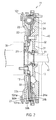
- FIG. 1 is a front elevational view of a flywheel in an embodiment;
- FIG. 2 is a sectional view of the flywheel shown in FIG. 1 taken along the line A-A of FIG. 1;
- FIG. 3 is a back view of the flywheel shown in FIG. 1;
- FIG. 4 is a perspective view showing a first embodiment of weakened portions;
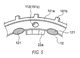
- FIG. 5 is a perspective view showing a second embodiment of the weakened portions; and
- FIG. 6 is a perspective view showing a third embodiment of the weakened portions.
- While the claims are not limited to the illustrated embodiments, an appreciation of various aspects of the disclosed flywheel is best gained through a discussion of various examples thereof. Referring now to the drawings, illustrative embodiments are shown in detail. Although the drawings represent the embodiments, the drawings are not necessarily to scale and certain features may be exaggerated to better illustrate and explain an innovative aspect of an embodiment. Further, the embodiments described herein are not intended to be exhaustive or otherwise limiting or restricting to the precise form and configuration shown in the drawings and disclosed in the following detailed description.
- A
flywheel 11 shown in FIGS. 1 to 3 is a disc-shaped member sized to have a significant moment of inertia, which is mounted on acrank shaft 30 of an engine. Theflywheel 11 is composed of afront cover 12 and arear cover 13, which constitute a flywheel cover and a coil spring unit (damper member) 14 composed of twocoil springs front cover 12 and therear cover 13. - The
front cover 12 is connected to thecrank shaft 30 of the engine, therear cover 13 is connected to anoutput shaft 41 through aclutch 40, and torque variation of the engine is absorbed by transmitting the rotation of thefront cover 12 to therear cover 13 through thecoil spring unit 14. - The
front cover 12 is composed of aflange unit 21, afront plate 22 and a coilaccommodating member 24. Theflange unit 21 is coupled with an end of thecrank shaft 30 of the engine. Thefront plate 22 is fixed to theflange unit 21. The coilaccommodating member 24 is coupled with the peripheral edge of thefront plate 22 and forms an annular coilspring accommodating portion 23 together with thefront plate 22. - The coil
spring accommodating portion 23 is formed to a circular shape whose lateral cross section in the diameter direction of the flywheel is larger than the maximum diameter of thecoil spring 14 and is provided withnarrow portions coil spring unit 14 at two positions across the center axis of the flywheel. The coilspring accommodating portion 23 is divided into two arc-shaped accommodating portions by these twonarrow portions - The two
coil springs narrow portions - The two
narrow portions spring accommodating portion 23 are formed as follows. The surface of thefront plate 22 is recessed, and thebottoms 22b ofrecessed portions 22a are projected into the coilspring accommodating portion 23. In addition, the portions of the surface of thecoil accommodating member 24 confronting therecessed portions 22a are also recessed, and thebottoms 24b of the recessedportions 24a are projected into the coilspring accommodating portion 23. Consequently, thebottoms 22b of therecessed portions 22a confront with thebottoms 24b of therecessed portions 24a at narrow intervals. - Note that gaps are formed between the
bottoms 22b of therecessed portions 22a and thebottoms 24b of therecessed portions 24a to permit aninner plate 32 to be described below to pass therethrough. - The
rear cover 13 has arear cover plate 31, which is supported to theflange unit 21 through abearing 51. Theinner plate 32 is fixed to the engine side edge face of therear cover plate 31. - A shaft (output shaft) 41 of an output side power transmission system member is coupled with the
rear cover 13 through theclutch 40. - The
inner plate 32 has a base portion having a diameter smaller than that of thecoil accommodating member 24 and twoengaging portions narrow portions - When the front cover 12 (the front plate 22) is rotated by the rotation of the engine, the rotation torque of the
front cover 12 is transmitted to theinner plate 32 through thenarrow portions coil springs rear cover 13 is driven in rotation. However, an abrupt change of torque is absorbed in such a manner that one of thecoil springs - Further, the
flywheel 11 includes asensor plate 101 that is fixed to detect a crank angle. - The
sensor plate 101 is composed of a ring-shapedmain body 101 a havingprojections 101b (to-be-detected portions) projecting from the peripheral edge thereof at predetermined angular intervals. A sensor (not shown) is disposed in confrontation with a position at which theprojections 101 b pass, and each time the sensor detects aprojection 101 b, it issues a detection signal showing that the crank shaft rotates a predetermined angle. - However, the to-be-detected portions arranged to the
sensor plate 101 are not limited to theprojections 101 b and may be a variety of openings and/or grooves. - The
sensor plate 101 is fixed to thefront plate 22 by being welded thereto at a plurality of positions. - The
front plate 22 is provided with therecessed portions 22a as described above, and themain body 101 a of thesensor plate 101 is fixed so as to cover therecessed portions 22a. The portions of themain body 101a of thesensor plate 101, which confront with, or correspond to, therecessed portions 22a, are composed of weakenedportions 101c that are less rigid than the other portion. - As shown in FIGS. 1 and 4, the weakened
portions 101c are formed by cutting off the portions of the inner peripheral edge of themain body 101a, which confront with therecessed portions 22a to a generally rectangular shape in conformity with the width of the recessedportions 22a in the peripheral direction thereof and reducing the rigidity thereof by partially narrowing the width of the ring-shapedmain body 101 a in a diameter direction bycutouts 111. - Further, as shown in FIG. 5, the weakened
portions 101c can be formed by reducing rigidity by opening a throughhole 112 to each of the portions of themain body 101a confronting with therecessed portions 22a. - Note that the weakened
portions 101c can be formed by opening a plurality of throughholes 112 to each of the portions of themain body 101 a overlapping with the recessedportions 22a. - Further, as shown in FIG. 6, the weakened
portions 101c can be formed by arranging the portions of themain body 101 a aligned with the recessedportions 22a asthin wall portions 113 having a wall thickness thinner than that of the other portion. - Each of the
thin wall portions 113 shown in FIG. 6 is formed to have a pair of inclining surfaces by forming the thinnest wall portions along the diameter direction of themain body 101a and gradually increasing the wall thickness of theportions 113 as they are apart from the thinnest wall portions in the peripheral direction thereof. - However, thin wall portions as the weakened
portions 101c can be formed by reducing the thickness of the portions of themain body 101 a confronting with the recessedportions 22a through steps. - Note that the weakened
portions 101 c can be formed by combining any ones of thecutouts 111, the throughholes 112, and thethin wall portions 113. - Further, when the
main body 101a composed of a plurality of individual parts is attached to thefront plate 22, the separating portions where the individual parts are separated from each other can be caused to act as the weakenedportions 101 c by locating the separating portions at the positions confronting with the recessedportions 22a. - Moreover, the portions of the
main body 101 a confronting with the recessedportions 22a can be caused to act as the weakenedportions 101 c by composing the portions of a material which is less rigid than the other portion. - Although the
sensor plate 101 to which the weakenedportions 101 c are formed as described above is welded at a plurality of positions of the inner peripheral edge thereof and coupled with thefront plate 22, weldedportions 121 are formed adjacent to both the sides of the weakenedportions 101 c in the peripheral direction thereof. - Assume that the
sensor plate 101 is provided with the weakenedportions 101c confronting with the recessedportions 22a. In this case, even if the front cover 12 (front plate 22) is deformed while the engine is in operation, the weakenedportions 101 c are easily deformed as the portion of thesensor plate 101 in intimate contact with thefront plate 22 is deformed. Consequently, stress applied to the welded portions 121 (coupling portions) in the vicinity of the recessedportions 22a can be suppressed. - Accordingly, it is possible to enhance reliability of the flywheel 11 (sensor plate 101).
- Note that the structure of the
flywheel 11 is not limited to the structure shown in FIGS. 1 to 3, and anyflywheel 11 which has recessed portions formed to the surface of a front cover 12 (front plate 22) to which asensor plate 101 is attached can achieve the same advantage by being applied with the flywheel structure having the weakened portions according to the present invention. - This application claims priority from
Japanese Patent Application No. 2006-148478 filed 29th May 2006
Claims (9)
- A flywheel apparatus for an engine having a flywheel cover and a sensor plate attached thereto, the flywheel cover including at least one recessed portion;
wherein the sensor plate comprises at least one weakened portion that corresponds to the at least one recessed portion. - A flywheel apparatus as claimed in claim 1, wherein the weakened portion comprises less material compared to adjacent portions of the sensor plate.
- A flywheel apparatus as claimed in claim 1 or claim 2, wherein the flywheel cover comprises a plurality of recessed portions and wherein the sensor plate comprises a weakened portion corresponding to each of the recessed portions.
- A flywheel apparatus as claimed in any preceding claim, wherein the sensor plate comprises a ring-shaped member and wherein the or each weakened portion comprises a portion of the sensor plate having a reduced width.
- A flywheel apparatus as claimed in any preceding claim, wherein the or each weakened portion comprises a portion having a through hole to the sensor plate.
- A flywheel apparatus as claimed in any preceding claim, wherein the or each weakened portion comprises a portion of the sensor plate having a reduced wall thickness.
- A flywheel apparatus as claimed in any preceding claim, wherein the sensor plate is attached to the flywheel cover by welding and wherein welded portions are arranged adjacent to the weakened portion in a peripheral direction to couple the flywheel cover with the sensor plate.
- An engine having an apparatus as claimed in any preceding claim.
- A vehicle having an apparatus or an engine as claimed in any preceding claim.
Applications Claiming Priority (1)
| Application Number | Priority Date | Filing Date | Title |
|---|---|---|---|
| JP2006148478A JP4797805B2 (en) | 2006-05-29 | 2006-05-29 | Flywheel with sensor plate |
Publications (2)
| Publication Number | Publication Date |
|---|---|
| EP1862696A1 true EP1862696A1 (en) | 2007-12-05 |
| EP1862696B1 EP1862696B1 (en) | 2014-11-05 |
Family
ID=38432854
Family Applications (1)
| Application Number | Title | Priority Date | Filing Date |
|---|---|---|---|
| EP07108937.9A Active EP1862696B1 (en) | 2006-05-29 | 2007-05-25 | Flywheel |
Country Status (3)
| Country | Link |
|---|---|
| US (1) | US8006589B2 (en) |
| EP (1) | EP1862696B1 (en) |
| JP (1) | JP4797805B2 (en) |
Families Citing this family (2)
| Publication number | Priority date | Publication date | Assignee | Title |
|---|---|---|---|---|
| EP2554421A3 (en) | 2011-08-01 | 2015-10-07 | Dana Limited | Method and apparatus for transferring power between a flywheel and a vehicle |
| JP7148363B2 (en) * | 2018-11-09 | 2022-10-05 | 株式会社Soken | Rotation angle detector |
Citations (8)
| Publication number | Priority date | Publication date | Assignee | Title |
|---|---|---|---|---|
| FR2526106A1 (en) * | 1982-04-29 | 1983-11-04 | Valeo | STARTER CROWN CLUTCH AND IGNITION TARGET, IN PARTICULAR FOR MOTOR VEHICLE |
| JPH05312053A (en) | 1992-05-08 | 1993-11-22 | Nissan Motor Co Ltd | Crank angle detector of engine |
| EP0780588A1 (en) * | 1995-12-20 | 1997-06-25 | Valeo | Clutch unit comprising a slitted target ring |
| DE19723104A1 (en) * | 1996-06-10 | 1997-12-11 | Valeo | Clutch unit esp. for motor vehicle |
| DE19710918A1 (en) * | 1997-03-15 | 1998-09-24 | Mannesmann Sachs Ag | Flywheel with annular additional mass |
| EP0952374A2 (en) * | 1998-04-22 | 1999-10-27 | Rohs-Voigt Patentverwertungsgesellschaft mbH | Torsional vibration damper and its method of manufacture |
| FR2812703A1 (en) * | 2000-08-07 | 2002-02-08 | Renault | Automobile internal combustion engine starter motor in which assembly of cylindrical ignition cage and a support is done by electric current discharge welding |
| GB2385107A (en) * | 1998-11-05 | 2003-08-13 | Luk Lamellen & Kupplungsbau | Folded element with ignition timing markings |
Family Cites Families (9)
| Publication number | Priority date | Publication date | Assignee | Title |
|---|---|---|---|---|
| US2982150A (en) * | 1959-09-17 | 1961-05-02 | Gen Motors Corp | Internal combustion engine flywheel |
| JPH0545874Y2 (en) * | 1985-09-20 | 1993-11-29 | ||
| JPH04287837A (en) * | 1991-03-18 | 1992-10-13 | Nissan Motor Co Ltd | Crank angle sensor |
| BR9303423A (en) * | 1992-08-20 | 1994-03-15 | Fichtel & Sachs Ag | TORQUE VIBRATION SHOCK ABSORBER |
| GB9620036D0 (en) * | 1996-09-26 | 1996-11-13 | Automotive Products Plc | A friction damper |
| JP2000304759A (en) * | 1999-04-26 | 2000-11-02 | Nissan Diesel Motor Co Ltd | Rotation detecting device |
| JP2001180297A (en) * | 1999-12-28 | 2001-07-03 | Nissan Diesel Motor Co Ltd | Engine mounting bracket |
| JP4269544B2 (en) * | 2000-09-14 | 2009-05-27 | 株式会社デンソー | Multi-rotor synchronous machine |
| JP2002201978A (en) * | 2001-01-09 | 2002-07-19 | Suzuki Motor Corp | Crank angle sensor structure |
-
2006
- 2006-05-29 JP JP2006148478A patent/JP4797805B2/en active Active
-
2007
- 2007-05-25 EP EP07108937.9A patent/EP1862696B1/en active Active
- 2007-05-25 US US11/807,154 patent/US8006589B2/en active Active
Patent Citations (8)
| Publication number | Priority date | Publication date | Assignee | Title |
|---|---|---|---|---|
| FR2526106A1 (en) * | 1982-04-29 | 1983-11-04 | Valeo | STARTER CROWN CLUTCH AND IGNITION TARGET, IN PARTICULAR FOR MOTOR VEHICLE |
| JPH05312053A (en) | 1992-05-08 | 1993-11-22 | Nissan Motor Co Ltd | Crank angle detector of engine |
| EP0780588A1 (en) * | 1995-12-20 | 1997-06-25 | Valeo | Clutch unit comprising a slitted target ring |
| DE19723104A1 (en) * | 1996-06-10 | 1997-12-11 | Valeo | Clutch unit esp. for motor vehicle |
| DE19710918A1 (en) * | 1997-03-15 | 1998-09-24 | Mannesmann Sachs Ag | Flywheel with annular additional mass |
| EP0952374A2 (en) * | 1998-04-22 | 1999-10-27 | Rohs-Voigt Patentverwertungsgesellschaft mbH | Torsional vibration damper and its method of manufacture |
| GB2385107A (en) * | 1998-11-05 | 2003-08-13 | Luk Lamellen & Kupplungsbau | Folded element with ignition timing markings |
| FR2812703A1 (en) * | 2000-08-07 | 2002-02-08 | Renault | Automobile internal combustion engine starter motor in which assembly of cylindrical ignition cage and a support is done by electric current discharge welding |
Also Published As
| Publication number | Publication date |
|---|---|
| JP2007315565A (en) | 2007-12-06 |
| EP1862696B1 (en) | 2014-11-05 |
| US8006589B2 (en) | 2011-08-30 |
| US20070295117A1 (en) | 2007-12-27 |
| JP4797805B2 (en) | 2011-10-19 |
Similar Documents
| Publication | Publication Date | Title |
|---|---|---|
| JP5379295B2 (en) | Roller type one-way clutch | |
| EP2541091B1 (en) | Roller-type one-way clutch | |
| US8931609B2 (en) | Roller-type one-way clutch | |
| US10180174B2 (en) | Fluctuation attenuator | |
| US8434605B2 (en) | One-way clutch of roller type for starter of motor bike | |
| US10151371B2 (en) | Torque transmission apparatus | |
| EP3620313B1 (en) | Fitting structure between functional component accomodation case and rubber base | |
| US8393453B2 (en) | One-way clutch of roller type | |
| JP2010116988A (en) | One-way clutch of roller type | |
| US8413778B2 (en) | One-way clutch of roller type | |
| EP1862696B1 (en) | Flywheel | |
| US20210164524A1 (en) | Clutch device | |
| EP1719929B1 (en) | Torque transmission device of compressor | |
| JP2009281487A (en) | Connection structure of crankshaft and rotary member | |
| JP3434040B2 (en) | Centrifugal pendulum type vibration absorber | |
| JP5555786B1 (en) | One-way clutch | |
| JP2007113525A (en) | Pedal module | |
| JP2015001234A (en) | Flywheel device | |
| JPH061016U (en) | Cover for airbag device | |
| JP2007247714A (en) | Connection structure of yoke and shaft |
Legal Events
| Date | Code | Title | Description |
|---|---|---|---|
| PUAI | Public reference made under article 153(3) epc to a published international application that has entered the european phase |
Free format text: ORIGINAL CODE: 0009012 |
|
| AK | Designated contracting states |
Kind code of ref document: A1 Designated state(s): AT BE BG CH CY CZ DE DK EE ES FI FR GB GR HU IE IS IT LI LT LU LV MC MT NL PL PT RO SE SI SK TR |
|
| AX | Request for extension of the european patent |
Extension state: AL BA HR MK YU |
|
| 17P | Request for examination filed |
Effective date: 20080605 |
|
| AKX | Designation fees paid |
Designated state(s): DE FR GB |
|
| 17Q | First examination report despatched |
Effective date: 20080825 |
|
| GRAP | Despatch of communication of intention to grant a patent |
Free format text: ORIGINAL CODE: EPIDOSNIGR1 |
|
| GRAS | Grant fee paid |
Free format text: ORIGINAL CODE: EPIDOSNIGR3 |
|
| INTG | Intention to grant announced |
Effective date: 20140905 |
|
| GRAA | (expected) grant |
Free format text: ORIGINAL CODE: 0009210 |
|
| AK | Designated contracting states |
Kind code of ref document: B1 Designated state(s): DE FR GB |
|
| REG | Reference to a national code |
Ref country code: GB Ref legal event code: FG4D |
|
| REG | Reference to a national code |
Ref country code: DE Ref legal event code: R096 Ref document number: 602007039106 Country of ref document: DE Effective date: 20141218 |
|
| REG | Reference to a national code |
Ref country code: DE Ref legal event code: R097 Ref document number: 602007039106 Country of ref document: DE |
|
| PLBE | No opposition filed within time limit |
Free format text: ORIGINAL CODE: 0009261 |
|
| STAA | Information on the status of an ep patent application or granted ep patent |
Free format text: STATUS: NO OPPOSITION FILED WITHIN TIME LIMIT |
|
| 26N | No opposition filed |
Effective date: 20150806 |
|
| REG | Reference to a national code |
Ref country code: FR Ref legal event code: PLFP Year of fee payment: 10 |
|
| REG | Reference to a national code |
Ref country code: FR Ref legal event code: PLFP Year of fee payment: 11 |
|
| REG | Reference to a national code |
Ref country code: FR Ref legal event code: PLFP Year of fee payment: 12 |
|
| PGFP | Annual fee paid to national office [announced via postgrant information from national office to epo] |
Ref country code: FR Payment date: 20230420 Year of fee payment: 17 Ref country code: DE Payment date: 20230419 Year of fee payment: 17 |
|
| PGFP | Annual fee paid to national office [announced via postgrant information from national office to epo] |
Ref country code: GB Payment date: 20230420 Year of fee payment: 17 |