EP1862598A2 - Interface plate for mounting a light duty attachment to a lift arm assembly - Google Patents
Interface plate for mounting a light duty attachment to a lift arm assembly Download PDFInfo
- Publication number
- EP1862598A2 EP1862598A2 EP07252146A EP07252146A EP1862598A2 EP 1862598 A2 EP1862598 A2 EP 1862598A2 EP 07252146 A EP07252146 A EP 07252146A EP 07252146 A EP07252146 A EP 07252146A EP 1862598 A2 EP1862598 A2 EP 1862598A2
- Authority
- EP
- European Patent Office
- Prior art keywords
- flange
- interface plate
- side edge
- interface
- aperture
- Prior art date
- Legal status (The legal status is an assumption and is not a legal conclusion. Google has not performed a legal analysis and makes no representation as to the accuracy of the status listed.)
- Granted
Links
Images






Classifications
-
- E—FIXED CONSTRUCTIONS
- E02—HYDRAULIC ENGINEERING; FOUNDATIONS; SOIL SHIFTING
- E02F—DREDGING; SOIL-SHIFTING
- E02F3/00—Dredgers; Soil-shifting machines
- E02F3/04—Dredgers; Soil-shifting machines mechanically-driven
- E02F3/28—Dredgers; Soil-shifting machines mechanically-driven with digging tools mounted on a dipper- or bucket-arm, i.e. there is either one arm or a pair of arms, e.g. dippers, buckets
- E02F3/36—Component parts
- E02F3/3604—Devices to connect tools to arms, booms or the like
-
- A—HUMAN NECESSITIES
- A01—AGRICULTURE; FORESTRY; ANIMAL HUSBANDRY; HUNTING; TRAPPING; FISHING
- A01B—SOIL WORKING IN AGRICULTURE OR FORESTRY; PARTS, DETAILS, OR ACCESSORIES OF AGRICULTURAL MACHINES OR IMPLEMENTS, IN GENERAL
- A01B59/00—Devices specially adapted for connection between animals or tractors and agricultural machines or implements
- A01B59/06—Devices specially adapted for connection between animals or tractors and agricultural machines or implements for machines mounted on tractors
- A01B59/061—Devices specially adapted for connection between animals or tractors and agricultural machines or implements for machines mounted on tractors specially adapted for enabling connection or disconnection controlled from the driver's seat
- A01B59/062—Devices specially adapted for connection between animals or tractors and agricultural machines or implements for machines mounted on tractors specially adapted for enabling connection or disconnection controlled from the driver's seat the connection comprising a rigid interface frame on the tractor
-
- E—FIXED CONSTRUCTIONS
- E02—HYDRAULIC ENGINEERING; FOUNDATIONS; SOIL SHIFTING
- E02F—DREDGING; SOIL-SHIFTING
- E02F3/00—Dredgers; Soil-shifting machines
- E02F3/04—Dredgers; Soil-shifting machines mechanically-driven
- E02F3/28—Dredgers; Soil-shifting machines mechanically-driven with digging tools mounted on a dipper- or bucket-arm, i.e. there is either one arm or a pair of arms, e.g. dippers, buckets
- E02F3/36—Component parts
- E02F3/3604—Devices to connect tools to arms, booms or the like
- E02F3/3609—Devices to connect tools to arms, booms or the like of the quick acting type, e.g. controlled from the operator seat
- E02F3/3627—Devices to connect tools to arms, booms or the like of the quick acting type, e.g. controlled from the operator seat with a hook and a longitudinal locking element
-
- E—FIXED CONSTRUCTIONS
- E02—HYDRAULIC ENGINEERING; FOUNDATIONS; SOIL SHIFTING
- E02F—DREDGING; SOIL-SHIFTING
- E02F3/00—Dredgers; Soil-shifting machines
- E02F3/04—Dredgers; Soil-shifting machines mechanically-driven
- E02F3/28—Dredgers; Soil-shifting machines mechanically-driven with digging tools mounted on a dipper- or bucket-arm, i.e. there is either one arm or a pair of arms, e.g. dippers, buckets
- E02F3/36—Component parts
- E02F3/3604—Devices to connect tools to arms, booms or the like
- E02F3/3609—Devices to connect tools to arms, booms or the like of the quick acting type, e.g. controlled from the operator seat
- E02F3/3668—Devices to connect tools to arms, booms or the like of the quick acting type, e.g. controlled from the operator seat where engagement is effected by a mechanical lever or handle
-
- E—FIXED CONSTRUCTIONS
- E02—HYDRAULIC ENGINEERING; FOUNDATIONS; SOIL SHIFTING
- E02F—DREDGING; SOIL-SHIFTING
- E02F3/00—Dredgers; Soil-shifting machines
- E02F3/04—Dredgers; Soil-shifting machines mechanically-driven
- E02F3/28—Dredgers; Soil-shifting machines mechanically-driven with digging tools mounted on a dipper- or bucket-arm, i.e. there is either one arm or a pair of arms, e.g. dippers, buckets
- E02F3/36—Component parts
- E02F3/3604—Devices to connect tools to arms, booms or the like
- E02F3/3609—Devices to connect tools to arms, booms or the like of the quick acting type, e.g. controlled from the operator seat
- E02F3/3672—Devices to connect tools to arms, booms or the like of the quick acting type, e.g. controlled from the operator seat where disengagement is effected by a mechanical lever or handle
Definitions
- the present invention relates to a self-propelled vehicle having a front lift arm assembly. More particularly, the present invention relates to a utility vehicle with an attachment arm assembly having an interface plate configured for mounting a light duty attachment or tool.
- a utility vehicle includes a frame attached to an operator compartment such as a cab.
- a cargo support is attached to the frame behind the cab.
- An attachment arm assembly is attached to the frame generally in front of the cab and centered on a longitudinal center line of the utility vehicle.
- the attachment arm assembly is movable with respect to the frame and can be attached to one or more work tools such as a bucket.
- the utility vehicle is suited for use in operating in a variety of different tasks.
- Utility vehicles are generally vehicles that can provide a versatile amount of uses.
- the present invention is directed to a self-propelled, work vehicle having an attachment arm assembly pivotably coupled to a front of a frame assembly at a frame pivot.
- the attachment arm assembly includes a pair of spaced-apart attachment arms coupled to an interface plate for mounting a tool to the work vehicle.
- the tool has an interface receiving member.
- the interface receiving member includes a pair of first and second side flanges having first and second ends.
- the interface receiving member also includes a top flange that couples the second end of the first side flange to the second end of the second side flange.
- the first ends of the first and second side flanges are spaced apart from each other a distance that is greater than a distance between the second ends of the first and second side flanges.
- the interface plate includes a first side edge having a first end and a second end.
- the first side edge corresponds with the first side flange of the interface receiving member.
- the interface plate also includes a second side edge having a first end and a second end.
- the second side edge corresponds with the second side flange of the interface receiving member.
- the interface plate also includes a top edge that corresponds with the top flange of the interface receiving member and couples the second end of the first side edge to the second end of the second side edge.
- the first ends of the first and second side edge are spaced apart from each other a distance greater than the second ends of the first and second side edges.
- the present invention is described in the context of a self-propelled, wheeled utility vehicle. However, it should be noted that the present invention can be used in connection with other types of work vehicles other than utility vehicles. For example, the present invention can be used in an all terrain vehicle or other types of small work vehicles.
- FIG. 1 illustrates a perspective view of an exemplary utility vehicle 10.
- the utility vehicle 10 includes a frame 12 supported with front and rear wheel assemblies 14, 16 respectively.
- the frame 12 is attached to a cab 18 that defines an operator compartment 20 having an operator platform, and a seat 22, and operator controls 24.
- the utility vehicle also includes an engine, not shown, typically disposed between the seat 22 and the rear wheel assembly 16 and attached to the frame 12.
- the frame 12 also is connected to a cargo support 26, which is disposed behind the seat 22 in the example.
- An attachment arm assembly 28 is positioned in front of the seat 22 and attached to the front portion of frame 12.
- the attachment arm assembly 28 is adapted to receive a removable tool 30, such as a blade 32 shown removed in FIG. 1.
- the frame 12 is a rigid frame assembly that provides generally no frame articulation between the front and rear wheel assemblies 14, 16.
- the frame 12 is illustrated as including longitudinal members 34 extending from the front wheel assembly 14 toward the rear wheel assembly 16.
- the frame includes a cargo support portion 36, a middle portion 38, and an attachment arm support portion 40.
- the attachment arm support portion 40 is particularly strengthened to resist bending or twisting from loads carried with attachment arm assembly 28.
- the middle portion 38 is adapted to provide a stable mount for the cab 18 and can be suited to accommodate a transverse mounted engine.
- the engine can power either or both of the wheel assemblies 14, 16 to move the utility vehicle 10.
- the engine is connected to one or both of the wheel assemblies 14, 16, with mechanical drives, hydraulic motors or other suitable devices for power transmission.
- the wheel assemblies 14, 16 can include suspension systems coupled to the frame 12.
- a steering linkage can be coupled to the front wheels, rear wheels, or both.
- Controls 24 for the operation of the utility vehicle 10 are mounted in the operator compartment 20.
- the operator compartment 20 includes an instrument cluster and dash 44 generally disposed in front of the seat 22, and includes gauges, controls and the like useful for comfort of the operator and operation of the work machine 10.
- the seat 22 can include one or more bucket seats or a common bench seat for two or more riders.
- FIG. 1 also shows the attachment arm assembly 28 connected to the attachment arm support portion 40 of the frame 12.
- the remote end of the attachment arm assembly 28 can be connected to an interface plate 46 that provides an interface for attaching to various tools 30.
- tools 30 can include blades, buckets, grapples, brooms, augers, pallet forks or other tools.
- the attachment arm assembly 28 is coupled to the frame 12 in such a manner that it can be moved with respect to the frame 12. Movement of the attachment arm assembly 28 is effected through the use of hydraulic actuators or other types of mechanical or electrical actuators that receive power from the engine.
- FIG. 2 is a more detailed view of the attachment arm assembly 28 shown decoupled from the frame 12.
- the attachment arm assembly 28 includes a pair of arms 50 and 51, an arm support portion 52 and interface plate 46.
- the pair of arms 50 and 51 are joined together by a cross member and are pivotally coupled about an arm pivot axis 54 of an arm support portion 52 at one end of the arms 50 and 51.
- Arms 50 and 51 are pivotally coupled about of interface plate pivot axis 56 on interface plate 46 at the other end of arms 50 and 51.
- Attachment arm assembly 28 also includes a lift cylinder (not illustrated) and a tilt cylinder 58 (illustrated in FIG. 1).
- the lift cylinder is generally positioned between arm support portion 52 and lift cylinder support 60.
- Tilt cylinder 58 is generally positioned between arm support portion 52 and cross-member 62 on interface plate 46.
- the lift cylinder lifts arms 50 and 51 about arm pivot axis 54 and tilt cylinder 58 tilts interface plate 46 about interface plate pivot axis 56.
- the lift cylinder (not illustrated) and tilt cylinder 58 are hydraulic cylinders that each include a body or cylinder portion and an extensible rod. The cylinders are actuated with operator controls and powered by the engine. It should be noted, however, utility vehicle 10 can lift arms 50 and 51 about arm pivot axis 54 and tilt interface plate 46 about interface plate pivot axis 56 with other types of mechanical or electrical actuators other than hydraulic cylinders.
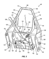
- FIG. 3 illustrates a more detailed view of interface plate 46.
- Interface plate 46 is configured to mount a tool to attachment arm assembly 28 of work machine 10.
- Interface plate 46 is also configured to dismount a tool from attachment arm assembly 28.
- Interface plate 46 can mount a variety of different tools as discussed and noted above. When interface plate 46 mounts or attaches a tool, it engages with the tool in an unlocked position and then actuates into a locked position to retain the tool. When interface plate 46 disengages from a tool, it actuates into an unlocked position and the tool is removed.
- interface plate 46 is configured in an unlocked position.
- Interface plate 46 includes a first side edge 102, a second side edge 104 and a top edge 106.
- the first side edge 102 includes a first end 108 and a second end 109.
- the second side edge 104 includes a first end (not shown in FIG. 3) and a second end 110.
- Second end 109 of first side edge 102 is integrally coupled to one end of top edge 106 and second end 110 of second side edge 104 is integrally coupled to the other end of top edge 106.
- First side edge 102, second side edge 104 and top edge 106 integrally form a cylindrical bar that surrounds a main body 112 of interface plate 46.
- First side edge 102 from first end 108 to second end 109 and second side edge 104 from the first end to second end 110 both span a distance that ranges from approximately 8 inches to 12 inches. In particular, the distance between first end 108 and second end 109 is approximately 10.5 inches.
- Top edge 106 has a length that ranges between approximately 3 inches and 6 inches. In particular, the length of top edge 106 is approximately 4.75 inches. The length of top edge 106 is equivalent to a distance between second end 109 and second end 110.
- First end 108 of first side edge 102 and the first end of second side edge 104 are spaced apart from each other a distance greater than a distance between second end 109 of first side edge 102 and second end 110 of second side edge 104.
- the distance between first end 108 of first side edge 102 and the first end of second side edge 104 ranges between approximately 11 and 15 inches. In particular, the distance between first end 108 of first side edge 102 and the first end of second side edge 104 is approximately 13.5 inches.
- the distance between first end 108 of first side edge 102 and the first end of second side edge 104 is between approximately 2.5 and 3 times greater than the distance between second end 108 of first side edge 102 and second end 110 of second side edge 104.
- Such relative distances provide main body 112 with a shape that is tapered at top edge 106 and broadened at first end 108 of first side edge 102 and the first end of second side edge 104.
- Interface plate 46 also includes a first outer flange 114 and a second outer flange 116.
- First outer flange 114 is coupled to first side edge 102 and second outer flange 116 is coupled to second side edge 104.
- Positioned between first outer flange 114 and second outer flange 116 are a first inner flange 118 and a second inner flange 120.
- First inner flange 118 is coupled to first side edge 102 at an upper portion 122
- second inner flange 120 is coupled to second side edge 104 at an upper portion 123. From upper portions 122 and 123, first and second inner flanges 118 and 120 extend substantially parallel with each other to lower portions 124 and 125, respectively.
- First outer flange 114 is coupled to first side edge 102 at an upper portion 126 and second outer flange 116 is coupled to second side edge 104 at an upper portion 127. From upper portions 126 and 127, first and second outer flanges 114 and 116 extend along first and second side edges 102 and 104, respectively, until middle portions 128 and 129 of first and second outer flanges 114 and 116. At middle portions. 128 and 129, first and second outer flanges 114 and 116 run substantially parallel with each other and substantially parallel with first and second inner flanges 118 and 120 to lower portions 130 and 131 of first outer flange 114 and second outer flange 116, respectively. First inner flange 118 is positioned in closer proximity to first outer flange 114 than second outer flange 116. Second inner flange 120 is positioned in closer proximity to second outer flange 116 than first outer flange 114.
- Lower portion 130 of first outer flange 114 and lower portion 124 of first inner flange 118 each include mounting apertures 132.
- Apertures 132 are configured to receive a cross-member for mounting arm 51 (FIG. 2) of attachment arm assembly 28 (FIG. 1 and 2) to interface plate 46.
- Lower portion 131 of second outer flange 116 and lower portion 125 of second inner flange 120 each include mounting apertures 133.
- Apertures 133 are configured to receive a cross-member for mounting arm 50 (FIG. 2) of attachment arm assembly 28.
- Above lower portions 131 and 125, each of second outer flange 116 and second inner flange 120 include another set of apertures 134.
- Apertures 134 are configured to receive a cross-member for mounting tilt cylinder 58 (FIG. 1) of attachment arm assembly 28 to interface plate 46.
- interface plate 46 includes a locking mechanism 136.
- Locking mechanism 136 includes a lever 138, a spring 140, a pair of pins 142 (of which one is illustrated in FIG. 3) and a guide plate 144.
- Guide plate 144 includes a slot 146 having a first catch feature 148 at one end of the slot and a second catch feature 149 at the other end of the slot.
- spring 140 is coupled to lever 138 as well as pins 142.
- locking mechanism 136 is in an unlocked position. In this position, pins 142 do not protrude through apertures 150. Pins that do not protrude through apertures 150 (of which one is shown in FIG. 3) do not interfere with a tool. Since spring 142 is biased in a locked position, lever 138 is constrained by first catch feature 148 of slot 146 such that pins do not protrude through apertures 150.
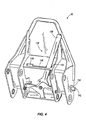
- FIG. 4 illustrates interface plate 46 in a locked position.
- lever 138 is slid long slot 146 and made to be constrained in second catch feature 149.
- pins 142 extend outwardly from apertures 150 (of which one is shown in FIG. 4).
- Locking mechanism 136 can be manually actuated applying a force to lever 138 to extend pins 142 outwardly, however, locking mechanism 136 can also be actuated with other mechanical or electro-mechanical actuators to extend pins 142 outwardly.
- spring 140 is biased to retain interface plate 46 in a locked position or with pins extended, second catch feature 149 is utilized to ensure that lever 138 does not slip from its locked position.
- FIG. 5 illustrates a more detailed view of tool 30.
- FIG. 5 is an illustrative embodiment of a tool and in this example is a blade 32.
- Tool 30 includes an interface receiving member 152.
- Interface receiving member 152 includes a first side flange 154 and a second side flange 156.
- First side flange 154 includes a first end 158 and a second end 159.
- Second side flange 156 includes a first end 160 and a second end 161.
- Interface receiving member 152 also includes a top flange 162.
- Second end 159 of first side flange 154 is coupled to one end of top flange 162.
- Second end 161 of second side flange 156 is coupled to the other end of top flange 162.
- First end 158 of first side flange 154 and first end 160 of second side flange 156 are spaced apart from each other a distance greater than a distance between second end 159 of first side edge 154 and second end 161 of second side flange 156.
- Such relative distances provide interface receiving member 152 with a shape that is tapered at top flange 162 and broadened at first ends 158 and 160 of first and second side flanges 154 and 156.
- the tapered shape and dimensions of interface receiving member 152 correspond with the tapered shape and dimensions of main body 112 (FIG.
- interface plate 46 (FIGS. 3 and 4).
- Corresponding tapered shapes allow interface receiving member 152 to receive main body 112 of interface plate 46.
- side edges 102 and 104 Upon mounting tool 30 to interface plate 46, side edges 102 and 104 will be proximate side flanges 154 and 156 and top edge 106 will be proximate top flange 162.
- First and second side flanges 154 and 156 of interface receiving member 152 each include an aperture 164 located near first ends 158 and 160. Apertures 164 are aligned with each other and are configured to receive pins 142 (FIGS. 3 and 4) of locking mechanism 136 (FIGS. 3 and 4) upon their extension from apertures 150 of interface plate 46. Upon apertures 164 receiving pins 142, interface plate 46 is mounted and locked with interface receiving member 152 of tool 30. Although not specifically illustrated, in an alternative embodiment, interface plate 46 does not include a locking mechanism. Instead, a single pin is inserted through both apertures 164 of interface receiving member 152 and through apertures 150 of interface plate 46. The single pin can lock interface plate 46 to a tool 30.
- FIG. 6 illustrates a side view of tool 30.
- second side flange 156, top flange 162 and one of the apertures 164 for receiving pins 142 (FIGS. 3 and 4) of locking mechanism 136 (FIGS. 3 and 4) are illustrated.
- top flange 162 forms a pocket 166 with the first side flange (not illustrated in FIG. 6) and second side flange 156.
- Pocket 166 is configured to receive top edge 106 of the integral cylindrical bar of interface plate 46. In a sense, pocket 166 surrounds the cylindrical bar of top edge 106 to more easily mount interface plate 46 with interface receiving member 152.
- FIGS. 7-1, 7-2 and 7-3 illustrate interface plate 46 being mounted to a tool 30.
- tool 30 is a pallet fork 33.
- interface plate 46 is constrained in an unlocked position as illustrated in FIG. 7-1. The unlocked position is clearly indicated by lever 138 being in a position oriented towards the left or within catch feature 148.
- interface plate 46 is tilted forward (in a direction 168 indicated by the arrow) using tilt cylinder 58.
Landscapes
- Engineering & Computer Science (AREA)
- Mechanical Engineering (AREA)
- Mining & Mineral Resources (AREA)
- Civil Engineering (AREA)
- General Engineering & Computer Science (AREA)
- Structural Engineering (AREA)
- Life Sciences & Earth Sciences (AREA)
- Zoology (AREA)
- Soil Sciences (AREA)
- Environmental Sciences (AREA)
- Forklifts And Lifting Vehicles (AREA)
- Harvester Elements (AREA)
- Lighting Device Outwards From Vehicle And Optical Signal (AREA)
- Shovels (AREA)
Abstract
Description
- The present invention relates to a self-propelled vehicle having a front lift arm assembly. More particularly, the present invention relates to a utility vehicle with an attachment arm assembly having an interface plate configured for mounting a light duty attachment or tool.
- A utility vehicle includes a frame attached to an operator compartment such as a cab. A cargo support is attached to the frame behind the cab. An attachment arm assembly is attached to the frame generally in front of the cab and centered on a longitudinal center line of the utility vehicle. The attachment arm assembly is movable with respect to the frame and can be attached to one or more work tools such as a bucket. The utility vehicle is suited for use in operating in a variety of different tasks. Utility vehicles are generally vehicles that can provide a versatile amount of uses.
- Often times it is necessary to attach a variety of different work tools to the front of a utility vehicle to operate in a variety of different tasks. However, the compact size of a utility vehicle requires that an interface that attaches a variety of different work tools also be compact as well as easy to use. Interface designs on large work machines are not well suited for the compact nature of a utility vehicle.
- The present invention is directed to a self-propelled, work vehicle having an attachment arm assembly pivotably coupled to a front of a frame assembly at a frame pivot. The attachment arm assembly includes a pair of spaced-apart attachment arms coupled to an interface plate for mounting a tool to the work vehicle.
- The tool has an interface receiving member. The interface receiving member includes a pair of first and second side flanges having first and second ends. The interface receiving member also includes a top flange that couples the second end of the first side flange to the second end of the second side flange. The first ends of the first and second side flanges are spaced apart from each other a distance that is greater than a distance between the second ends of the first and second side flanges.
- The interface plate includes a first side edge having a first end and a second end. The first side edge corresponds with the first side flange of the interface receiving member. The interface plate also includes a second side edge having a first end and a second end. The second side edge corresponds with the second side flange of the interface receiving member. The interface plate also includes a top edge that corresponds with the top flange of the interface receiving member and couples the second end of the first side edge to the second end of the second side edge. The first ends of the first and second side edge are spaced apart from each other a distance greater than the second ends of the first and second side edges.
-
- FIG. 1 illustrates a perspective view of a utility vehicle.
- FIG. 2 illustrates a detailed view of an attachment arm assembly.
- FIG. 3 illustrates a detailed view of an interface plate in an unlocked position.
- FIG. 4 illustrates the interface plate of FIG. 3 in an locked position.
- FIG. 5 illustrates a detailed view of a tool.
- FIG. 6 illustrates a side view of the tool illustrated in FIG. 5.
- FIGS. 7-1 through 7-3 illustrate the process of mounting a tool to an interface plate.
- The present invention is described in the context of a self-propelled, wheeled utility vehicle. However, it should be noted that the present invention can be used in connection with other types of work vehicles other than utility vehicles. For example, the present invention can be used in an all terrain vehicle or other types of small work vehicles.
- FIG. 1 illustrates a perspective view of an
exemplary utility vehicle 10. Theutility vehicle 10 includes aframe 12 supported with front andrear wheel assemblies frame 12 is attached to acab 18 that defines anoperator compartment 20 having an operator platform, and aseat 22, and operator controls 24. The utility vehicle also includes an engine, not shown, typically disposed between theseat 22 and therear wheel assembly 16 and attached to theframe 12. Theframe 12 also is connected to acargo support 26, which is disposed behind theseat 22 in the example. Anattachment arm assembly 28 is positioned in front of theseat 22 and attached to the front portion offrame 12. Theattachment arm assembly 28 is adapted to receive aremovable tool 30, such as ablade 32 shown removed in FIG. 1. - In a typical example, the
frame 12 is a rigid frame assembly that provides generally no frame articulation between the front andrear wheel assemblies frame 12 is illustrated as includinglongitudinal members 34 extending from thefront wheel assembly 14 toward therear wheel assembly 16. The frame includes acargo support portion 36, amiddle portion 38, and an attachmentarm support portion 40. The attachmentarm support portion 40 is particularly strengthened to resist bending or twisting from loads carried withattachment arm assembly 28. Themiddle portion 38 is adapted to provide a stable mount for thecab 18 and can be suited to accommodate a transverse mounted engine. - The engine can power either or both of the wheel assemblies 14, 16 to move the
utility vehicle 10. The engine is connected to one or both of thewheel assemblies wheel assemblies frame 12. A steering linkage can be coupled to the front wheels, rear wheels, or both.Controls 24 for the operation of theutility vehicle 10 are mounted in theoperator compartment 20. - The
operator compartment 20 includes an instrument cluster anddash 44 generally disposed in front of theseat 22, and includes gauges, controls and the like useful for comfort of the operator and operation of thework machine 10. Theseat 22 can include one or more bucket seats or a common bench seat for two or more riders. - FIG. 1 also shows the
attachment arm assembly 28 connected to the attachmentarm support portion 40 of theframe 12. The remote end of theattachment arm assembly 28 can be connected to aninterface plate 46 that provides an interface for attaching tovarious tools 30.Such tools 30 can include blades, buckets, grapples, brooms, augers, pallet forks or other tools. Theattachment arm assembly 28 is coupled to theframe 12 in such a manner that it can be moved with respect to theframe 12. Movement of theattachment arm assembly 28 is effected through the use of hydraulic actuators or other types of mechanical or electrical actuators that receive power from the engine. - FIG. 2 is a more detailed view of the
attachment arm assembly 28 shown decoupled from theframe 12. Theattachment arm assembly 28 includes a pair ofarms arm support portion 52 andinterface plate 46. The pair ofarms arm pivot axis 54 of anarm support portion 52 at one end of thearms Arms plate pivot axis 56 oninterface plate 46 at the other end ofarms -
Attachment arm assembly 28 also includes a lift cylinder (not illustrated) and a tilt cylinder 58 (illustrated in FIG. 1). The lift cylinder is generally positioned betweenarm support portion 52 andlift cylinder support 60.Tilt cylinder 58 is generally positioned betweenarm support portion 52 and cross-member 62 oninterface plate 46. The lift cylinder liftsarms arm pivot axis 54 andtilt cylinder 58tilts interface plate 46 about interfaceplate pivot axis 56. In theexemplary utility vehicle 10, the lift cylinder (not illustrated) andtilt cylinder 58 are hydraulic cylinders that each include a body or cylinder portion and an extensible rod. The cylinders are actuated with operator controls and powered by the engine. It should be noted, however,utility vehicle 10 can liftarms arm pivot axis 54 andtilt interface plate 46 about interfaceplate pivot axis 56 with other types of mechanical or electrical actuators other than hydraulic cylinders. - FIG. 3 illustrates a more detailed view of
interface plate 46.Interface plate 46 is configured to mount a tool toattachment arm assembly 28 ofwork machine 10.Interface plate 46 is also configured to dismount a tool fromattachment arm assembly 28.Interface plate 46 can mount a variety of different tools as discussed and noted above. Wheninterface plate 46 mounts or attaches a tool, it engages with the tool in an unlocked position and then actuates into a locked position to retain the tool. Wheninterface plate 46 disengages from a tool, it actuates into an unlocked position and the tool is removed. - In the embodiment illustrated in FIG. 3
interface plate 46 is configured in an unlocked position.Interface plate 46 includes afirst side edge 102, asecond side edge 104 and atop edge 106. Thefirst side edge 102 includes afirst end 108 and asecond end 109. Thesecond side edge 104 includes a first end (not shown in FIG. 3) and asecond end 110.Second end 109 offirst side edge 102 is integrally coupled to one end oftop edge 106 andsecond end 110 ofsecond side edge 104 is integrally coupled to the other end oftop edge 106.First side edge 102,second side edge 104 andtop edge 106 integrally form a cylindrical bar that surrounds amain body 112 ofinterface plate 46.First side edge 102 fromfirst end 108 tosecond end 109 andsecond side edge 104 from the first end tosecond end 110 both span a distance that ranges from approximately 8 inches to 12 inches. In particular, the distance betweenfirst end 108 andsecond end 109 is approximately 10.5 inches.Top edge 106 has a length that ranges between approximately 3 inches and 6 inches. In particular, the length oftop edge 106 is approximately 4.75 inches. The length oftop edge 106 is equivalent to a distance betweensecond end 109 andsecond end 110. -
First end 108 offirst side edge 102 and the first end ofsecond side edge 104 are spaced apart from each other a distance greater than a distance betweensecond end 109 offirst side edge 102 andsecond end 110 ofsecond side edge 104. The distance betweenfirst end 108 offirst side edge 102 and the first end ofsecond side edge 104 ranges between approximately 11 and 15 inches. In particular, the distance betweenfirst end 108 offirst side edge 102 and the first end ofsecond side edge 104 is approximately 13.5 inches. The distance betweenfirst end 108 offirst side edge 102 and the first end ofsecond side edge 104 is between approximately 2.5 and 3 times greater than the distance betweensecond end 108 offirst side edge 102 andsecond end 110 ofsecond side edge 104. Such relative distances providemain body 112 with a shape that is tapered attop edge 106 and broadened atfirst end 108 offirst side edge 102 and the first end ofsecond side edge 104. -
Interface plate 46 also includes a firstouter flange 114 and a secondouter flange 116. Firstouter flange 114 is coupled tofirst side edge 102 and secondouter flange 116 is coupled tosecond side edge 104. Positioned between firstouter flange 114 and secondouter flange 116 are a firstinner flange 118 and a secondinner flange 120. Firstinner flange 118 is coupled tofirst side edge 102 at anupper portion 122 and secondinner flange 120 is coupled tosecond side edge 104 at anupper portion 123. Fromupper portions inner flanges portions outer flange 114 is coupled tofirst side edge 102 at anupper portion 126 and secondouter flange 116 is coupled tosecond side edge 104 at anupper portion 127. Fromupper portions outer flanges middle portions outer flanges outer flanges inner flanges lower portions outer flange 114 and secondouter flange 116, respectively. Firstinner flange 118 is positioned in closer proximity to firstouter flange 114 than secondouter flange 116. Secondinner flange 120 is positioned in closer proximity to secondouter flange 116 than firstouter flange 114. -
Lower portion 130 of firstouter flange 114 andlower portion 124 of firstinner flange 118 each include mountingapertures 132.Apertures 132 are configured to receive a cross-member for mounting arm 51 (FIG. 2) of attachment arm assembly 28 (FIG. 1 and 2) tointerface plate 46.Lower portion 131 of secondouter flange 116 andlower portion 125 of secondinner flange 120 each include mountingapertures 133.Apertures 133 are configured to receive a cross-member for mounting arm 50 (FIG. 2) ofattachment arm assembly 28. Abovelower portions outer flange 116 and secondinner flange 120 include another set ofapertures 134.Apertures 134 are configured to receive a cross-member for mounting tilt cylinder 58 (FIG. 1) ofattachment arm assembly 28 to interfaceplate 46. - Between first
inner flange 118 and secondinner flange 120,interface plate 46 includes alocking mechanism 136.Locking mechanism 136 includes alever 138, aspring 140, a pair of pins 142 (of which one is illustrated in FIG. 3) and aguide plate 144.Guide plate 144 includes aslot 146 having afirst catch feature 148 at one end of the slot and asecond catch feature 149 at the other end of the slot. - In general and as illustrated in FIG. 3,
spring 140 is coupled to lever 138 as well as pins 142. In FIG. 3,locking mechanism 136 is in an unlocked position. In this position, pins 142 do not protrude throughapertures 150. Pins that do not protrude through apertures 150 (of which one is shown in FIG. 3) do not interfere with a tool. Sincespring 142 is biased in a locked position,lever 138 is constrained byfirst catch feature 148 ofslot 146 such that pins do not protrude throughapertures 150. - FIG. 4 illustrates
interface plate 46 in a locked position. To actuateinterface plate 46 into a locked position from an unlocked position,lever 138 is slidlong slot 146 and made to be constrained insecond catch feature 149. In such a locked position, pins 142 extend outwardly from apertures 150 (of which one is shown in FIG. 4).Locking mechanism 136 can be manually actuated applying a force to lever 138 to extendpins 142 outwardly, however,locking mechanism 136 can also be actuated with other mechanical or electro-mechanical actuators to extendpins 142 outwardly. Althoughspring 140 is biased to retaininterface plate 46 in a locked position or with pins extended,second catch feature 149 is utilized to ensure thatlever 138 does not slip from its locked position. - FIG. 5 illustrates a more detailed view of
tool 30. FIG. 5 is an illustrative embodiment of a tool and in this example is ablade 32.Tool 30 includes aninterface receiving member 152.Interface receiving member 152 includes afirst side flange 154 and asecond side flange 156.First side flange 154 includes afirst end 158 and asecond end 159.Second side flange 156 includes afirst end 160 and asecond end 161.Interface receiving member 152 also includes atop flange 162. -
Second end 159 offirst side flange 154 is coupled to one end oftop flange 162.Second end 161 ofsecond side flange 156 is coupled to the other end oftop flange 162.First end 158 offirst side flange 154 andfirst end 160 ofsecond side flange 156 are spaced apart from each other a distance greater than a distance betweensecond end 159 offirst side edge 154 andsecond end 161 ofsecond side flange 156. Such relative distances provideinterface receiving member 152 with a shape that is tapered attop flange 162 and broadened at first ends 158 and 160 of first andsecond side flanges interface receiving member 152 correspond with the tapered shape and dimensions of main body 112 (FIG. 3) of interface plate 46 (FIGS. 3 and 4). Corresponding tapered shapes allowinterface receiving member 152 to receivemain body 112 ofinterface plate 46. Upon mountingtool 30 to interfaceplate 46, side edges 102 and 104 will beproximate side flanges top edge 106 will be proximatetop flange 162. - First and
second side flanges interface receiving member 152 each include anaperture 164 located near first ends 158 and 160.Apertures 164 are aligned with each other and are configured to receive pins 142 (FIGS. 3 and 4) of locking mechanism 136 (FIGS. 3 and 4) upon their extension fromapertures 150 ofinterface plate 46. Uponapertures 164 receivingpins 142,interface plate 46 is mounted and locked withinterface receiving member 152 oftool 30. Although not specifically illustrated, in an alternative embodiment,interface plate 46 does not include a locking mechanism. Instead, a single pin is inserted through bothapertures 164 ofinterface receiving member 152 and throughapertures 150 ofinterface plate 46. The single pin can lockinterface plate 46 to atool 30. - FIG. 6 illustrates a side view of
tool 30. In FIG. 6,second side flange 156,top flange 162 and one of theapertures 164 for receiving pins 142 (FIGS. 3 and 4) of locking mechanism 136 (FIGS. 3 and 4) are illustrated. As illustrated more clearly in FIG. 6,top flange 162 forms apocket 166 with the first side flange (not illustrated in FIG. 6) andsecond side flange 156.Pocket 166 is configured to receivetop edge 106 of the integral cylindrical bar ofinterface plate 46. In a sense,pocket 166 surrounds the cylindrical bar oftop edge 106 to more easily mountinterface plate 46 withinterface receiving member 152. - FIGS. 7-1, 7-2 and 7-3 illustrate
interface plate 46 being mounted to atool 30. In the examples illustrated in FIGS. 7-1, 7-2 and 7-3,tool 30 is apallet fork 33. To begin mountinginterface plate 46 totool 30,interface plate 46 is constrained in an unlocked position as illustrated in FIG. 7-1. The unlocked position is clearly indicated bylever 138 being in a position oriented towards the left or withincatch feature 148. To proceed with mountinginterface plate 46 totool 30 as illustrated in FIG. 7-1,interface plate 46 is tilted forward (in adirection 168 indicated by the arrow) usingtilt cylinder 58. After tiltinginterface plate 46 forward, the work machine is driven towardsinterface receiving member 152 untiltop edge 106 ofinterface plate 46 is undertop flange 160 ofinterface receiving member 152. In FIG. 7-2,tilt cylinder 58tilts interface plate 46 backward until the bottom edge of the tool is slightly off the ground. This motion fully allowsinterface receiving member 152 to receiveinterface plate 46. In FIG. 7-3,lever 138 is actuated fromcatch feature 148 toward the right into catch feature 149 (in adirection 170 indicated by the arrow) to lockinterface plate 46 totool 30. By actuatinglever 138 fromcatch feature 148 to catchfeature 149, pins 142 extend throughapertures 164 oninterface receiving member 152.Pins 142 that are extended throughapertures 164 provide secure fastening ofinterface plate 46 totool 30. To releasetool 30 frominterface plate 46, the steps are performed in reverse. - Although the present invention has now been described with reference to preferred embodiments, workers skilled in the art will recognize that changes may be made in form and detail without departing from the spirit and scope of the invention.
- Attention is directed to all papers and documents which are filed concurrently with or previous to this specification in connection with this application and which are open to public inspection with this specification, and the contents of all such papers and documents are incorporated herein by reference.
- All of the features disclosed in this specification (including any accompanying claims, abstract and drawings), and/or all of the steps of any method or process so disclosed, may be combined in any combination, except combinations where at least some of such features and/or steps are mutually exclusive.
- Each feature disclosed in this specification (including any accompanying claims, abstract and drawings) may be replaced by alternative features serving the same, equivalent or similar purpose, unless expressly stated otherwise. Thus, unless expressly stated otherwise, each feature disclosed is one example only of a generic series of equivalent or similar features.
- The invention is not restricted to the details of the foregoing embodiment(s). The invention extends to any novel one, or any novel combination, of the features disclosed in this specification (including any accompanying claims, abstract and drawings), or to any novel one, or any novel combination, of the steps of any method or process so disclosed.
Claims (19)
- A detachable tool for a work vehicle, the tool comprising:an interface receiving member including:a pair of first and second side flanges having first ends and second ends; anda top flange that couples the second end of the first side flange to the second end of the second side flange, wherein the first ends of the first and second side flanges are spaced apart from each other a distance that is greater than a distance between the second ends of the first and second side flanges.
- The detachable tool of claim 1, wherein the interface receiving member further comprises a pocket formed by the top flange and second ends of the first and second side flanges, the pocket configured to receive a top edge of an interface plate that is coupled to the work vehicle.
- The detachable tool of claim 1, wherein the first side flange includes a first aperture proximate the first end of the first side flange and the second side flange includes a second aperture proximate the first end of the second side flange, wherein the first aperture is in alignment with the second aperture.
- The detachable tool of claim 3, wherein the first and second apertures are configured to receive a pin for locking the tool to an interface plate on the work vehicle.
- The detachable tool of claim 4, wherein the first aperture is configured to receive a first pin and the second aperture is configured to receive a second pin, wherein the first pin and the second pin are coupled to and actuated by the interface plate for locking the tool to the work vehicle.
- A work vehicle comprising:a tool having an interface receiving member comprising:a pair of first and second side flanges having first and second ends;a top flange that couples the second end of the first side flange to the second end of the second side flange, wherein the first ends of the first and second side flanges are spaced apart from each other a distance that is greater than the second ends of the first and second side flanges;an interface plate coupled to a lift arm of the work vehicle, the interface plate configured to be received by the interface receiving member, the interface plate comprising:a first side edge having a first end and a second end, the first side edge supporting the first side flange of the interface receiving member;a second side edge having a first end and a second end, the second side edge supporting the second side flange of the interface receiving member; anda top edge that interfaces supports the top flange of the interface receiving member and couples the second end of the first side edge to the second end of the second side edge, wherein the first ends of the first and second side edge are spaced apart from each other a distance greater than a distance between the second ends of the first and second side edges.
- The work vehicle of claim 6, wherein the distance between the first ends of the first and second side edges is approximately between 2.5 and three times greater than the distance between the second ends of the first and second side edges.
- The work vehicle of claim 6, wherein the first side edge, the second side edge and the top edge form an integral cylindrical bar that surrounds a main body of the interface plate.
- The work vehicle of claim 8, wherein the interface receiving member comprises a pocket formed by the top flange, the second end of the first side flange and the second end of the second side flange, wherein the pocket is configured to receive the of the top edge of the cylindrical bar of the interface plate.
- The work vehicle of claim 6, wherein the first side flange of the interface receiving member comprises a first aperture and the second side flange of the interface receiving member comprises a second aperture in alignment with the first aperture.
- The work vehicle of claim 10, wherein the interface plate comprises;a first outer flange coupled to and extending along the first side edge;a second outer flange coupled to and extending along the second side edge;a first inner flange positioned between the first outer flange and the second outer flange and closer to the first outer flange than to the second outer flange; anda second inner flange positioned between the first inner flange and the second outer flange and closer to the second outer flange than the first outer flange.
- The work vehicle of claim 11, wherein the interface plate comprises a locking mechanism positioned between the first inner flange and the second inner flange for locking the interface plate to the interface receiving member.
- The work vehicle of claim 14, wherein the locking mechanism includes a lever, a spring, a first pin and a second pin.
- The work vehicle of claim 13, wherein upon actuation of the lever, the spring operates to actuate the first pin through an aperture in the first outer flange of the interface plate and through the first aperture in the first side flange of the interface receiving member and operates to actuate the second pin through an aperture in the second outer flange of the interface plate and through the second aperture in the second side flange of the interface receiving member.
- The work vehicle of claim 13, wherein the interface plate comprises a guide plate having a slot located between the first inner flange and the second inner flange, the slot configured to surround at least a portion of the lever and comprise a first catch feature located at one end of the slot and a second catch feature located at an opposite end of the slot, wherein the first catch feature is configured to retain the lever in an unlocked position and the second catch feature is configured to retain the lever in a locked position.
- An attachment arm assembly comprising:an attachment arm pivotal about an arm pivot axis ;an interface plate pivotal about an interface plate pivot axis and configured to mount a tool,the interface plate having a main body and comprising:a first side edge having a first end and a second end;a second side edge having a first end and a second end; anda top edge that couples the second end of the first side edge to the second end of the second side edge, wherein the first ends of the first and second side edge are spaced apart from each other a distance greater than a distance between the second ends of the first and second side edges.
- The attachment arm assembly of claim 16, wherein the first side edge, the second side edge and the top edge form an integral cylindrical bar that surrounds the main body of the interface plate.
- The attachment arm assembly of claim 16, wherein the distance between the first ends of the first and second side edges is approximately 13.5 inches and the distance between the second ends of the first and second side edges is approximately 4.75 inches.
- The attachment arm assembly of claim 18, wherein the interface plate comprises a locking mechanism positioned between the first inner flange and the second inner flange, the locking mechanism including a first pin that extends outwardly from the first outer flange to mate with a first aperture in a tool and a second pin that extends outwardly from the second outer flange to mate with a second aperture in the tool.
Applications Claiming Priority (1)
| Application Number | Priority Date | Filing Date | Title |
|---|---|---|---|
| US11/421,509 US7699577B2 (en) | 2006-06-01 | 2006-06-01 | Interface plate for mounting a light duty attachment to a lift arm assembly |
Publications (3)
| Publication Number | Publication Date |
|---|---|
| EP1862598A2 true EP1862598A2 (en) | 2007-12-05 |
| EP1862598A3 EP1862598A3 (en) | 2008-04-30 |
| EP1862598B1 EP1862598B1 (en) | 2016-11-23 |
Family
ID=38472991
Family Applications (1)
| Application Number | Title | Priority Date | Filing Date |
|---|---|---|---|
| EP07252146.1A Not-in-force EP1862598B1 (en) | 2006-06-01 | 2007-05-25 | Interface plate for mounting a light duty attachment to a lift arm assembly |
Country Status (5)
| Country | Link |
|---|---|
| US (1) | US7699577B2 (en) |
| EP (1) | EP1862598B1 (en) |
| AU (1) | AU2007202372A1 (en) |
| CA (1) | CA2590107C (en) |
| ES (1) | ES2616040T3 (en) |
Cited By (3)
| Publication number | Priority date | Publication date | Assignee | Title |
|---|---|---|---|---|
| ITTO20100312A1 (en) * | 2010-04-16 | 2011-10-17 | Giovanni Andrina | QUICK ATTACHMENT TO CONNECT A TOOL TO A HANDLING EQUIPMENT, AS THE ARM OF AN EXCAVATOR |
| GB2543331A (en) * | 2015-10-15 | 2017-04-19 | Bamford Excavators Ltd | Quick hitch |
| EP3556546A1 (en) * | 2018-04-19 | 2019-10-23 | Heinz Bergmann e.Kfm. Maschinen für die Abfallwirtschaft | Mobile roller compressor and handling method |
Families Citing this family (12)
| Publication number | Priority date | Publication date | Assignee | Title |
|---|---|---|---|---|
| US20100025058A1 (en) * | 2006-06-19 | 2010-02-04 | Clark Equipment Company | Attachment arm removal and actuator storage |
| US8444367B2 (en) * | 2008-07-18 | 2013-05-21 | Clark Equipment Company | Locking device for securing a backhoe attachment to a carrier lift arm |
| US8689898B2 (en) * | 2010-01-09 | 2014-04-08 | Brian Anthony Benesch | Removable loader for all-terrain and utility-terrain vehicles |
| US20120121323A1 (en) * | 2010-11-12 | 2012-05-17 | Hill Curt J | Quick-attach assembly for attaching an implement to an off-road vehicle |
| US8763715B2 (en) * | 2011-05-11 | 2014-07-01 | Ralph L. Osgood, Inc. | Quick-connect plow hitch |
| US8474892B1 (en) * | 2012-06-13 | 2013-07-02 | Pinnacle Companies, Inc. | Lifting apparatus and method |
| US9809945B1 (en) * | 2015-06-08 | 2017-11-07 | Robert Middleton | Method, apparatus, and kit for providing an adapter on earth moving equipment |
| US10322924B2 (en) * | 2017-07-28 | 2019-06-18 | Frizzie Corp. | Low impact mobile and modular fuel delivery apparatus and kit |
| US10279764B1 (en) * | 2017-10-27 | 2019-05-07 | Iddea California, Llc | Skid plate assembly |
| US20200016977A1 (en) | 2018-07-10 | 2020-01-16 | Venture Products, Inc. | Belt drive power unit |
| WO2022232437A1 (en) | 2021-04-28 | 2022-11-03 | Workhorse Atv, Llc | All-terrain vehicle systems and methods |
| CA3141241A1 (en) | 2021-12-03 | 2023-06-03 | Ariens Company | Implement for skid steer vehicle |
Citations (2)
| Publication number | Priority date | Publication date | Assignee | Title |
|---|---|---|---|---|
| EP0197026A2 (en) | 1985-03-26 | 1986-10-08 | Josef Steiner | Quick hitch coupling for agricultural machines |
| EP1103171A1 (en) | 1999-11-27 | 2001-05-30 | McVeigh, David Creighton | Tractor coupling |
Family Cites Families (32)
| Publication number | Priority date | Publication date | Assignee | Title |
|---|---|---|---|---|
| US2888995A (en) | 1954-11-17 | 1959-06-02 | Deere & Co | Hitch device |
| US3285625A (en) | 1964-12-29 | 1966-11-15 | Wausau Iron Works | Quick coupler |
| US3417886A (en) | 1967-06-07 | 1968-12-24 | Clifton F. Stuart | Implement hitch for tractors and loaders |
| US3672521A (en) | 1969-11-05 | 1972-06-27 | James J Bauer | Quick attachment device |
| US3876091A (en) | 1974-07-26 | 1975-04-08 | Rivinius Inc | Implement connecting coupling mechanism |
| GB1475202A (en) | 1975-01-04 | 1977-06-01 | Massey Ferguson Perkins Ltd | Loader vehicles |
| US3985249A (en) | 1975-04-14 | 1976-10-12 | International Harvester Company | Quick change attachment |
| US4119225A (en) * | 1977-04-18 | 1978-10-10 | Owatonna Manufacturing Company, Inc. | Mounting means for attaching an implement to a vehicle |
| US4307992A (en) | 1979-10-11 | 1981-12-29 | Raygo Wagner, Inc. | Load handling vehicle with a bucket side tilt mechanism |
| WO1981002086A1 (en) | 1980-01-24 | 1981-08-06 | Bercato | Device for coupling together an implement with an implement carrier |
| GB2132584B (en) * | 1982-12-24 | 1986-08-28 | Dobson Park Ind | Releasable connection device |
| AT379048B (en) | 1983-03-01 | 1985-11-11 | Steiner Josef | QUICK COUPLING FOR CONNECTING AGRICULTURAL WORKING MACHINES |
| US4708579A (en) | 1984-07-27 | 1987-11-24 | Jrb Company, Inc. | Hydraulically or manually actuated implement coupler for front end loaders |
| US4824319A (en) * | 1987-09-02 | 1989-04-25 | Wain-Roy, Inc. | Loader coupler |
| US4812103A (en) * | 1988-03-22 | 1989-03-14 | J. I. Case Company | Implement-coupling assembly for material-handling apparatus |
| US4984957A (en) | 1988-08-08 | 1991-01-15 | Kubota, Ltd. | Work-implement adapter for front loader |
| US5310275A (en) * | 1989-11-30 | 1994-05-10 | Lovitt Estel L | Universal coupler |
| US5078569A (en) | 1990-04-30 | 1992-01-07 | J. I. Case Company | Quick attaching mechanism for a front-end loader |
| US5082065A (en) | 1990-08-15 | 1992-01-21 | Support Services International, Inc. | Quick attach implement coupler |
| US5419673A (en) | 1993-03-11 | 1995-05-30 | Memo Industrial Planning, Inc. | Quick disconnect apparatus for tractor front loader |
| JP2803807B2 (en) | 1993-03-17 | 1998-09-24 | 株式会社坂戸工作所 | Connector for construction work machine |
| DE4327942C1 (en) | 1993-08-19 | 1995-01-05 | Deere & Co | Device for fixing a tool on a hoist |
| US5692855A (en) | 1994-06-21 | 1997-12-02 | Farmers' Factory Co. | Automatic quick-connect coupler for implements |
| US5685689A (en) | 1996-01-03 | 1997-11-11 | Great Bend Manufacturing Co., Inc. | Quick attach system for front end loader |
| US5743339A (en) | 1996-02-09 | 1998-04-28 | Alexander, Iii; William J. | Tractor hitch and method |
| US5950735A (en) | 1996-03-25 | 1999-09-14 | Godbersen; Byron L. | Universal assembly for coupling towable agricultural implement to a towing vehicle |
| EP1353011A1 (en) | 2002-03-27 | 2003-10-15 | Rädlinger Maschinen- und Anlagenbau GmbH | Device for coupling a working implement to a construction machine |
| DE10221941A1 (en) | 2002-05-17 | 2003-12-04 | Deere & Co | Device for fixing a tool on a hoist |
| DE10221942A1 (en) | 2002-05-17 | 2003-12-04 | Deere & Co | Device for fixing a tool on a hoist |
| SE523299C2 (en) | 2002-07-15 | 2004-04-06 | Stock Of Sweden Ab | Device for connecting an implement to an implement carrier |
| US6925735B2 (en) | 2002-08-30 | 2005-08-09 | Deere & Co. | Bumper, skid plate and attachment system for utility vehicle |
| SE0402366L (en) | 2004-09-29 | 2006-03-14 | Aaloe Ab | Device and method for attaching a implement to a loader |
-
2006
- 2006-06-01 US US11/421,509 patent/US7699577B2/en active Active
-
2007
- 2007-05-24 AU AU2007202372A patent/AU2007202372A1/en not_active Abandoned
- 2007-05-25 ES ES07252146.1T patent/ES2616040T3/en active Active
- 2007-05-25 CA CA2590107A patent/CA2590107C/en active Active
- 2007-05-25 EP EP07252146.1A patent/EP1862598B1/en not_active Not-in-force
Patent Citations (2)
| Publication number | Priority date | Publication date | Assignee | Title |
|---|---|---|---|---|
| EP0197026A2 (en) | 1985-03-26 | 1986-10-08 | Josef Steiner | Quick hitch coupling for agricultural machines |
| EP1103171A1 (en) | 1999-11-27 | 2001-05-30 | McVeigh, David Creighton | Tractor coupling |
Cited By (5)
| Publication number | Priority date | Publication date | Assignee | Title |
|---|---|---|---|---|
| ITTO20100312A1 (en) * | 2010-04-16 | 2011-10-17 | Giovanni Andrina | QUICK ATTACHMENT TO CONNECT A TOOL TO A HANDLING EQUIPMENT, AS THE ARM OF AN EXCAVATOR |
| GB2543331A (en) * | 2015-10-15 | 2017-04-19 | Bamford Excavators Ltd | Quick hitch |
| US10883244B2 (en) | 2015-10-15 | 2021-01-05 | J. C. Bamford Excavators Limited | Quick hitch |
| GB2543331B (en) * | 2015-10-15 | 2021-06-23 | Bamford Excavators Ltd | Quick hitch |
| EP3556546A1 (en) * | 2018-04-19 | 2019-10-23 | Heinz Bergmann e.Kfm. Maschinen für die Abfallwirtschaft | Mobile roller compressor and handling method |
Also Published As
| Publication number | Publication date |
|---|---|
| EP1862598B1 (en) | 2016-11-23 |
| US7699577B2 (en) | 2010-04-20 |
| CA2590107A1 (en) | 2007-12-01 |
| CA2590107C (en) | 2014-08-05 |
| US20070280810A1 (en) | 2007-12-06 |
| AU2007202372A1 (en) | 2007-12-20 |
| EP1862598A3 (en) | 2008-04-30 |
| ES2616040T3 (en) | 2017-06-09 |
Similar Documents
| Publication | Publication Date | Title |
|---|---|---|
| EP1862598B1 (en) | Interface plate for mounting a light duty attachment to a lift arm assembly | |
| EP1947249B1 (en) | Common pivot and support member for an attachment interface of a loader | |
| CA1307767C (en) | Work-implement adapter for front loader | |
| US6718663B1 (en) | Assembly for coupling implements to excavating machines | |
| US7160076B2 (en) | Work machine with boom stop | |
| JP2007154519A (en) | Work vehicle and skid steer loader | |
| EP2310578B1 (en) | Locking device for securing a backhoe attachment to a carrier lift arm | |
| US7591336B2 (en) | Pin disengaging assembly and a method of disengaging pins of a trailer tandem | |
| US10145082B2 (en) | Work vehicle and backhoe | |
| US6957705B2 (en) | Loader linkage | |
| CN108779615B (en) | Working device for motor grader and motor grader | |
| JP2006016764A (en) | Quick coupler device of work vehicle | |
| EP4454979B1 (en) | Work vehicle | |
| US6368050B1 (en) | Fork lifts | |
| JP3693794B2 (en) | Work equipment mounting device for passenger management work vehicle | |
| US20060120843A1 (en) | Apparatus for moving a load between lowered and inclined positions | |
| JP2003129512A (en) | Tractor-mounted backhoe | |
| KR20210068941A (en) | Excavator with Fork Lift | |
| JPH11243713A (en) | Work machine mounting structure | |
| JPH0715487U (en) | Allowable load varying device for cargo handling vehicles | |
| JPH08108999A (en) | Fork shift device | |
| NZ505519A (en) | Fork lift tines with open area at mounting end for visibility from operator end of tips of tines | |
| JPH04187002A (en) | Detachable type front loader | |
| EP1810908A1 (en) | Handling appliance |
Legal Events
| Date | Code | Title | Description |
|---|---|---|---|
| PUAI | Public reference made under article 153(3) epc to a published international application that has entered the european phase |
Free format text: ORIGINAL CODE: 0009012 |
|
| AK | Designated contracting states |
Kind code of ref document: A2 Designated state(s): AT BE BG CH CY CZ DE DK EE ES FI FR GB GR HU IE IS IT LI LT LU LV MC MT NL PL PT RO SE SI SK TR |
|
| AX | Request for extension of the european patent |
Extension state: AL BA HR MK YU |
|
| PUAL | Search report despatched |
Free format text: ORIGINAL CODE: 0009013 |
|
| AK | Designated contracting states |
Kind code of ref document: A3 Designated state(s): AT BE BG CH CY CZ DE DK EE ES FI FR GB GR HU IE IS IT LI LT LU LV MC MT NL PL PT RO SE SI SK TR |
|
| AX | Request for extension of the european patent |
Extension state: AL BA HR MK RS |
|
| 17P | Request for examination filed |
Effective date: 20081003 |
|
| 17Q | First examination report despatched |
Effective date: 20081104 |
|
| AKX | Designation fees paid |
Designated state(s): DE ES FR GB IT |
|
| GRAP | Despatch of communication of intention to grant a patent |
Free format text: ORIGINAL CODE: EPIDOSNIGR1 |
|
| INTG | Intention to grant announced |
Effective date: 20160629 |
|
| GRAS | Grant fee paid |
Free format text: ORIGINAL CODE: EPIDOSNIGR3 |
|
| GRAA | (expected) grant |
Free format text: ORIGINAL CODE: 0009210 |
|
| AK | Designated contracting states |
Kind code of ref document: B1 Designated state(s): DE ES FR GB IT |
|
| REG | Reference to a national code |
Ref country code: GB Ref legal event code: FG4D |
|
| REG | Reference to a national code |
Ref country code: DE Ref legal event code: R096 Ref document number: 602007048853 Country of ref document: DE |
|
| REG | Reference to a national code |
Ref country code: FR Ref legal event code: PLFP Year of fee payment: 11 |
|
| REG | Reference to a national code |
Ref country code: ES Ref legal event code: FG2A Ref document number: 2616040 Country of ref document: ES Kind code of ref document: T3 Effective date: 20170609 |
|
| PGFP | Annual fee paid to national office [announced via postgrant information from national office to epo] |
Ref country code: FR Payment date: 20170525 Year of fee payment: 11 Ref country code: GB Payment date: 20170530 Year of fee payment: 11 Ref country code: DE Payment date: 20170530 Year of fee payment: 11 |
|
| REG | Reference to a national code |
Ref country code: DE Ref legal event code: R097 Ref document number: 602007048853 Country of ref document: DE |
|
| PGFP | Annual fee paid to national office [announced via postgrant information from national office to epo] |
Ref country code: ES Payment date: 20170601 Year of fee payment: 11 Ref country code: IT Payment date: 20170524 Year of fee payment: 11 |
|
| PLBE | No opposition filed within time limit |
Free format text: ORIGINAL CODE: 0009261 |
|
| STAA | Information on the status of an ep patent application or granted ep patent |
Free format text: STATUS: NO OPPOSITION FILED WITHIN TIME LIMIT |
|
| 26N | No opposition filed |
Effective date: 20170824 |
|
| REG | Reference to a national code |
Ref country code: DE Ref legal event code: R119 Ref document number: 602007048853 Country of ref document: DE |
|
| GBPC | Gb: european patent ceased through non-payment of renewal fee |
Effective date: 20180525 |
|
| PG25 | Lapsed in a contracting state [announced via postgrant information from national office to epo] |
Ref country code: GB Free format text: LAPSE BECAUSE OF NON-PAYMENT OF DUE FEES Effective date: 20180525 Ref country code: DE Free format text: LAPSE BECAUSE OF NON-PAYMENT OF DUE FEES Effective date: 20181201 Ref country code: IT Free format text: LAPSE BECAUSE OF NON-PAYMENT OF DUE FEES Effective date: 20180525 Ref country code: FR Free format text: LAPSE BECAUSE OF NON-PAYMENT OF DUE FEES Effective date: 20180531 |
|
| REG | Reference to a national code |
Ref country code: ES Ref legal event code: FD2A Effective date: 20190913 |
|
| PG25 | Lapsed in a contracting state [announced via postgrant information from national office to epo] |
Ref country code: ES Free format text: LAPSE BECAUSE OF NON-PAYMENT OF DUE FEES Effective date: 20180526 |