US5082065A - Quick attach implement coupler - Google Patents
Quick attach implement coupler Download PDFInfo
- Publication number
- US5082065A US5082065A US07/567,975 US56797590A US5082065A US 5082065 A US5082065 A US 5082065A US 56797590 A US56797590 A US 56797590A US 5082065 A US5082065 A US 5082065A
- Authority
- US
- United States
- Prior art keywords
- implement
- vertical
- coupler
- support
- bracket
- Prior art date
- Legal status (The legal status is an assumption and is not a legal conclusion. Google has not performed a legal analysis and makes no representation as to the accuracy of the status listed.)
- Expired - Fee Related
Links
Images


Classifications
-
- E—FIXED CONSTRUCTIONS
- E02—HYDRAULIC ENGINEERING; FOUNDATIONS; SOIL SHIFTING
- E02F—DREDGING; SOIL-SHIFTING
- E02F3/00—Dredgers; Soil-shifting machines
- E02F3/04—Dredgers; Soil-shifting machines mechanically-driven
- E02F3/28—Dredgers; Soil-shifting machines mechanically-driven with digging tools mounted on a dipper- or bucket-arm, i.e. there is either one arm or a pair of arms, e.g. dippers, buckets
- E02F3/36—Component parts
- E02F3/3604—Devices to connect tools to arms, booms or the like
- E02F3/3609—Devices to connect tools to arms, booms or the like of the quick acting type, e.g. controlled from the operator seat
- E02F3/3631—Devices to connect tools to arms, booms or the like of the quick acting type, e.g. controlled from the operator seat with a hook and a transversal locking element
-
- A—HUMAN NECESSITIES
- A01—AGRICULTURE; FORESTRY; ANIMAL HUSBANDRY; HUNTING; TRAPPING; FISHING
- A01B—SOIL WORKING IN AGRICULTURE OR FORESTRY; PARTS, DETAILS, OR ACCESSORIES OF AGRICULTURAL MACHINES OR IMPLEMENTS, IN GENERAL
- A01B59/00—Devices specially adapted for connection between animals or tractors and agricultural machines or implements
- A01B59/06—Devices specially adapted for connection between animals or tractors and agricultural machines or implements for machines mounted on tractors
- A01B59/061—Devices specially adapted for connection between animals or tractors and agricultural machines or implements for machines mounted on tractors specially adapted for enabling connection or disconnection controlled from the driver's seat
- A01B59/062—Devices specially adapted for connection between animals or tractors and agricultural machines or implements for machines mounted on tractors specially adapted for enabling connection or disconnection controlled from the driver's seat the connection comprising a rigid interface frame on the tractor
-
- A—HUMAN NECESSITIES
- A01—AGRICULTURE; FORESTRY; ANIMAL HUSBANDRY; HUNTING; TRAPPING; FISHING
- A01B—SOIL WORKING IN AGRICULTURE OR FORESTRY; PARTS, DETAILS, OR ACCESSORIES OF AGRICULTURAL MACHINES OR IMPLEMENTS, IN GENERAL
- A01B71/00—Construction or arrangement of setting or adjusting mechanisms, of implement or tool drive or of power take-off; Means for protecting parts against dust, or the like; Adapting machine elements to or for agricultural purposes
- A01B71/06—Special adaptations of coupling means between power take-off and transmission shaft to the implement or machine
-
- B—PERFORMING OPERATIONS; TRANSPORTING
- B60—VEHICLES IN GENERAL
- B60K—ARRANGEMENT OR MOUNTING OF PROPULSION UNITS OR OF TRANSMISSIONS IN VEHICLES; ARRANGEMENT OR MOUNTING OF PLURAL DIVERSE PRIME-MOVERS IN VEHICLES; AUXILIARY DRIVES FOR VEHICLES; INSTRUMENTATION OR DASHBOARDS FOR VEHICLES; ARRANGEMENTS IN CONNECTION WITH COOLING, AIR INTAKE, GAS EXHAUST OR FUEL SUPPLY OF PROPULSION UNITS IN VEHICLES
- B60K25/00—Auxiliary drives
- B60K25/06—Auxiliary drives from the transmission power take-off
-
- B—PERFORMING OPERATIONS; TRANSPORTING
- B62—LAND VEHICLES FOR TRAVELLING OTHERWISE THAN ON RAILS
- B62D—MOTOR VEHICLES; TRAILERS
- B62D49/00—Tractors
- B62D49/06—Tractors adapted for multi-purpose use
-
- E—FIXED CONSTRUCTIONS
- E01—CONSTRUCTION OF ROADS, RAILWAYS, OR BRIDGES
- E01H—STREET CLEANING; CLEANING OF PERMANENT WAYS; CLEANING BEACHES; DISPERSING OR PREVENTING FOG IN GENERAL CLEANING STREET OR RAILWAY FURNITURE OR TUNNEL WALLS
- E01H1/00—Removing undesirable matter from roads or like surfaces, with or without moistening of the surface
-
- E—FIXED CONSTRUCTIONS
- E01—CONSTRUCTION OF ROADS, RAILWAYS, OR BRIDGES
- E01H—STREET CLEANING; CLEANING OF PERMANENT WAYS; CLEANING BEACHES; DISPERSING OR PREVENTING FOG IN GENERAL CLEANING STREET OR RAILWAY FURNITURE OR TUNNEL WALLS
- E01H5/00—Removing snow or ice from roads or like surfaces; Grading or roughening snow or ice
- E01H5/04—Apparatus propelled by animal or engine power; Apparatus propelled by hand with driven dislodging or conveying levelling elements, conveying pneumatically for the dislodged material
- E01H5/06—Apparatus propelled by animal or engine power; Apparatus propelled by hand with driven dislodging or conveying levelling elements, conveying pneumatically for the dislodged material dislodging essentially by non-driven elements, e.g. scraper blades, snow-plough blades, scoop blades
-
- E—FIXED CONSTRUCTIONS
- E02—HYDRAULIC ENGINEERING; FOUNDATIONS; SOIL SHIFTING
- E02F—DREDGING; SOIL-SHIFTING
- E02F3/00—Dredgers; Soil-shifting machines
- E02F3/04—Dredgers; Soil-shifting machines mechanically-driven
- E02F3/627—Devices to connect beams or arms to tractors or similar self-propelled machines, e.g. drives therefor
Definitions
- the present invention relates to couplers for quickly attaching implements to vehicles.
- Utility-type vehicles are commonly used to perform a number of different jobs.
- the same vehicle may be used to plow, till, brush, blow, transport or drill.
- Each job requires the attachment of a specialized implement.
- Implements which mount directly to the vehicle may be heavy and cumbersome and require that the vehicle operator dismount to couple the implements to the vehicle.
- Quick attach couplers are known for connecting implements to earthmoving equipment, particularly different buckets to front-end loaders.
- front-end loaders need only to be raised and lowered
- implements such as plows, snowblowers and brooms need also to be rotatable in a horizontal plane.
- the apparatus for coupling an implement to the front end of a vehicle of this invention has a plurality of brackets connected to the vehicle. Each bracket has a lower portion with a frontwardly opening slot and a hole for receiving a pin spaced above the slot.
- a coupler is adapted for attachment to the brackets on the vehicle and has an upright brace with two vertical members joined by a horizontal member.
- a frame is pivotally mounted to the vertical members beneath the horizontal member and an actuator connects the brace and the frame so that the frame may be pivoted towards and away from the brace.
- a support is pivotally mounted about a vertical axis and has an upturned flange adapted to engage beneath a downturned J-shaped bracket on the implement and has pinholes located beneath the flange to receive pins extending from the implement.
- An implement coupling mechanism is fixed to the implement and consists of a downturned J-shaped bracket with a vertical portion and an opposed portion which is approximately as deep as the upward extension of the flange on the coupler.
- Vertical plates are connected on either side of the J-shaped bracket and are spaced to fit on either side of the support of the coupler.
- the plates are mounted to an implement.
- Spring-loaded locking pins are located on each vertical plate so that the pins may travel freely through holes in the plates to engage within the locking holes of the coupler.
- the vertical plates of the coupling mechanism have rounded out-turned edges which horizontally align the implement coupler with the implement.
- a further object of the present invention is to provide a coupling unit which may be easily and rapidly attached and detached from the vehicle.
- Another object of the present invention is to provide a quick attach coupler which is rotatable in a horizontal plane.
- Yet another object of the present invention is to provide a coupling mechanism for an implement which is adapted to quick attachment to a vehicle coupler.
- a still further object of the present invention is to provide a quick attach coupler for a vehicle which can elevate an implement above grade or lower it below grade.
- FIG. 1 is an exploded isometric view of the quick attach coupler and mounting bracket of this invention connected to the front end of a tractor.
- FIG. 2 is a perspective view of a snowplow to which is mounted the quick attach mechanism of this invention.
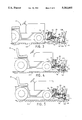
- FIG. 3 and the plow of FIG. 2 resting on the ground prior to attachment to the mounting brackets of FIG. 1 on a conventional tractor.
- FIG. 4 is a side elevational view of the quick attach coupler of FIG. 3 mounted on the mounting brackets connected to the tractor and positioned beneath the quick attach mechanism of the plow.
- FIG. 5 is a side elevational view of the quick attach coupler of FIG. 4 fully coupled to the quick attach mechanism of the plow.
- FIG. 5 is a top plan view of the connected mounting brackets, coupler and implement of FIG. 5.
- FIG. 6 is a top plan view of the assembly of FIG. 6 with the plow in a full left position.
- FIG. 7 is a side view of the assembly of FIG. 6 with the coupling mechanism of the implement partially broken away.
- FIG. 1 a quick attach coupler 20 is shown in FIG. 1.
- the coupler 20 is used for mounting implements to a vehicle.
- An implement is any attachment or accessory used in connection with the vehicle for transporting or doing work.
- the coupler 20 is detachably mounted to the front of a vehicle, here illustrated as a conventional tractor 22, by engagement with two vertical mounting brackets 24.
- the coupler 20 has an upright brace or mounting frame 26 which consists of two vertical members joined by a horizontal crossbar.
- the vertical members 28 are spaced by the crossbar 30 to fit on the outside of the mounting brackets 24 which connected to the tractor 22 by two bolts 32 or may be conventionally provided by the tractor mounting frame.
- a cylindrical pin 33 is located at the lower end of each vertical member 28 and is positioned to engage within aligned oblong slots 34 in the lower portions 36 of the mounting brackets 24.
- the oblong slots 34 are inclined upwardly somewhat to retain the fixed pins 33 of the connected coupler 20 against horizontal movement.
- Spring-loaded pins 38 are mounted in pin brackets 40 on the vertical members 28 above the fixed pins 33.
- a generally triangular A-frame 44 is pivotally connected to the mounting frame 26 by a rod 46 running through bushings 48 on the rear of the A-frame 44 and through holes 50 in the vertical members 28 forward of the fixed pins 33.
- the rod 46 is held in place by cotter pins 52.
- the A-frame 44 has a planar top plate 54 which has two side plates 56 which connect the top plate 54 to a bottom plate 58 which extends downwardly from the bushings 48 to a front portion which is parallel to the top plate 54.
- the bushings 48, the top plate 54, the side plates 56 and the bottom plate 58 are rigidly connected such as by welding to make the A-frame 44 a rigid box-like structure.
- the A-frame 44 is pivoted about the rod 46 by a vertical actuator 62 which is preferably a hydraulic cylinder.
- the actuator 62 is pivotally connected to the horizontal crossbar 30 by a bracket 64, and is pivotally connected to the A-frame 44 by a second bracket 66.
- the travel of the A-frame 44 will depend on the size and extension of the actuator 62, but in the preferred embodiment, the A-frame 44 may be rotated sufficiently to raise an attached implement twelve inches above grade and to depress it three inches below grade.
- An implement support 68 is pivotally connected at the apex 70 of the A-frame 44 by a pin 72.
- the implement support 68 has an upper plate 74 joined by side plates 76 to a pivoting table 78.
- the upper plate 74 has an upturned flange 80.
- the flange extends slightly more than one-half inch above the surface of the upper plate 74.
- the flange 80 is an extended linear flange, and is preferably formed as one piece with the upper plate 74. Additional rigidity is imparted to the implement supports 68 by front plates 82 which are connected to the side plates 76 and the pivoting table 78 but which need not be connected directly to the upper plate 74.
- the upper plate 74, side plates 76, and front plates 82 as well as the flange 80 may be formed of a single bent sheet of steel plate.
- a locking hole 102 is located in each support side plate 76 and is of suitable diameter for receiving the locking pins 104 mounted on the implement 108.
- a beveled surface 75 is formed where the front plates 82 meet the side plates 76 of the support, forward of the locking holes 102.
- the surfaces 75 act as cams to gradually depress the spring mounted locking pins 104 on the implement 108 when the coupler 20 is connected to the implement coupling mechanism 106 on the implement 108.
- the pivoting table 78 has an upper pivot plate 84 and a bottom pivot plate 86 connected by sides 88 to form a rigid box.
- the upper and bottom pivot plates 84, 86 have a series of radial holes 90 which accept a locking rod 92 spring-loaded in a bracket 94 mounted on the top plate 54 of the A-frame 44 for locking the implement support 68 at a fixed angle to the A-frame 44.
- the implement support 68 is pivoted on the A-frame 44 about the pin 72 by a horizontal actuator 96 which is preferably a hydraulic cylinder and piston assembly
- the actuator 96 is pivotally connected to the A-frame 44 by a bracket 98 fixed to the top plate 54 adjacent the bushings 48, and is pivotally connected to the support 68 by a bracket 100.
- Locking holes 102 extend through the side plates 76 of the implement support 68 and the sides 88 of the pivoting table 78 and are adapted to engage with the locking pins 104 of an implement coupling mechanism 106 attached to an implement 108, as shown in FIG. 2.
- the implement 108 illustrated is a conventional snowplow, but may be any implement for mounting to a vehicle, for example, a snowblower, a tiller or a broom.
- the implement coupling mechanism 106 consists of a downturned J-shaped bracket 110 mounted to two vertical side plates 120 above two spring-loaded locking pins 104 running through the plates 120.
- the downturned J-shaped bracket 110 has a vertical portion 112 and an opposed portion 114 which extends downwardly approximately the same distance as the flange 80 extends upwardly from the upper plate 74 of the implement support 68.
- the opposed portion 114 is inclined outwardly somewhat from the vertical portion 112 and the two portions 112, 114 define a wedge-shaped space which acts to capture the inserted flange 80 of the support 68.
- the vertical portion 112 is preferably longer than the opposed portion to serve as an abutment against which the approaching coupler 20 may make contact.
- the vertical portion 112 then acts to direct the flange 80 into engagement between the opposed portion and the vertical portion.
- the bracket 110 is connected at its ends to the vertical side plates 120. Each side plate has radiused out-turned edges 121 which assist in aligning the coupler 20 with the coupling mechanism 106 on the implement 108.
- the locking pins 104 are located on the side plates 120 beneath the J-shaped bracket 110 and are on either side of the J-shaped bracket 110. The locking pins 104 are spaced from the bracket 110 such that when the bracket 110 is engaged on the upturn flange 80 the locking pins 104 will be in position to engage with the locking holes 102 of the coupler 20.
- the locking pins 104 are retained in brackets 122 mounted on the vertical plates 120 adjacent clearance holes 124 to permit the movement of the locking pins 104 which are spring-loaded by springs 126 engaging with protruding studs 128 extending from each locking pin 104.
- the exemplary implement 108 shown has a plow blade 116 and two feet 118 which support the implement 108 and the implement coupling mechanism 106 in an upright position.
- the coupling mechanism 106 is connected to the implement 108 by the two opposed vertical plates 120.
- FIGS. 3, 4 and 5 The operation of the quick attach coupler 20 and implement coupling mechanism 106 of this invention is illustrated in FIGS. 3, 4 and 5.
- the tractor 22 has been parked adjacent the coupler 20 and the implement 108 which are resting on the ground 130 in upright positions.
- the operator dismounts from the tractor and lifts the coupler 20 and slides the fixed pins 33 of the mounting frame 26 into the oblong slots 34 of the mounting brackets 24. With the weight of the coupler 20 substantially supported by the mounting brackets 24 the coupler 20 is rotated towards the tractor 22.
- the spring-loaded pins 38 in the vertical members 28 of the mounting frame 26 are positioned over the through holes 42 in the mounting brackets 24 and with the spring-loaded pins 38 released from their retracted positions, the springs 39 urge the pins to engage in the through holes 42.
- the operator may quickly attach an implement to the tractor 22 without having to dismount from the tractor 22.
- the vertical actuator 62 is activated to depress the A-frame 44 and the connected implement support 68 so that the implement support 68 is angled downwardly towards the ground 130 as shown in FIG. 4.
- the tractor 22 is advanced towards the implement 108 which is resting with the locking pins 104 released and urged by the springs 126 to extend through the vertical plates 120.
- the tractor 22 is advanced towards the implement 108 until the upturned flange 80 is positioned directly below the downturned J-shaped bracket 110 of the implement coupling mechanism 106 of the implement 108.
- the curved edges 121 of the vertical plates 120 guide the implement coupler 20 into proper alignment with the implement coupling mechanism 106.
- the operator may then raise the support to bring the flange 80 into engagement between the vertical portion 112 and the opposed portion 114 of the downturned J-shaped bracket 110.
- the coupler 20 is thus engaged with the implement 108 by activating the vertical actuator 62 to rotate the A-frame 44 and the implement support 68 about the bushings 48 to raise the upturned flange 80 into engagement with the J-shaped bracket 110 of the implement coupling mechanism 106.
- the locking pins 104 of the implement coupling mechanism travel over the beveled surfaces 75 of the implement support 68, being depressed against the springs 126 until the locking pins 104 are positioned over the locking holes 102 at which point the springs 126 drive the locking pins 104 into engagement with the locking holes 102.
- the implement coupling mechanism 106 and the implement 108 are securely attached to the coupler 20 and the tractor 22.
- the weight of the implement 108 is carried by the upturned flange 80 of the support 68 and is distributed along the linear length of the flange 80.
- the attached implement may be raised or lowered as desired for transporting the implement or performing work, by hydraulic operation of the vertical actuator 62.
- the horizontal actuator 96 may be used to turn the implement to the right or the left (as shown in FIG. 7). In the preferred embodiment, the horizontal actuator 96 is sufficient to rotate the implement 30° to the right or to the left.
- the hydraulic control system of the tractor may additionally permit the implement to float and follow the terrain when desired.
- the implement support 68 may be locked into position by use of the locking rod 92 which may be inserted into any of the holes 90 in the pivoting table 78.
- the locking pins 104 of the implement coupling mechanism 106 are pulled outward into the retracted position engaging the studs 128 on the pins 104 within slots 129 on the brackets 122.
- the A-frame 44 and the implement support 68 are rotated downwardly by activating the vertical actuator 62 until the upturned flange 80 is disengaged from the L-shaped bracket 110 freeing the coupler 20 to move away from the implement 108.
- the implement coupling mechanism 106 may be affixed to any conventional implement. Hence, an operator may rapidly exchange implements. It should be noted that the particular shape of the vertical plates 120 and the structure for connecting the implement coupling mechanism 106 to the implement may vary depending on the configuration of the implement to which the coupling mechanism 106 is affixed. Although, for clarity, an under-vehicle mower has not been illustrated, the present bracket 24 and coupler 20 assembly may easily be mounted on a vehicle having such a mower mounted thereon without interference.
- the coupler has been illustrated attached to the front end of a vehicle, it may also be effectively attached to the back of a vehicle if desired.
- the vehicle illustrated is a tractor, the coupler may be attached to any vehicle, including a utility cart, a truck, a lift truck or other vehicle.
Landscapes
- Engineering & Computer Science (AREA)
- Mechanical Engineering (AREA)
- Life Sciences & Earth Sciences (AREA)
- Civil Engineering (AREA)
- Structural Engineering (AREA)
- General Engineering & Computer Science (AREA)
- Mining & Mineral Resources (AREA)
- Soil Sciences (AREA)
- Environmental Sciences (AREA)
- Chemical & Material Sciences (AREA)
- Combustion & Propulsion (AREA)
- Transportation (AREA)
- Architecture (AREA)
- Zoology (AREA)
- Agricultural Machines (AREA)
Abstract
Description
Claims (12)
Priority Applications (2)
| Application Number | Priority Date | Filing Date | Title |
|---|---|---|---|
| US07/567,975 US5082065A (en) | 1990-08-15 | 1990-08-15 | Quick attach implement coupler |
| US07/613,351 US5040615A (en) | 1990-08-15 | 1990-11-15 | Quick attaching power-take-off conversion unit |
Applications Claiming Priority (1)
| Application Number | Priority Date | Filing Date | Title |
|---|---|---|---|
| US07/567,975 US5082065A (en) | 1990-08-15 | 1990-08-15 | Quick attach implement coupler |
Related Child Applications (1)
| Application Number | Title | Priority Date | Filing Date |
|---|---|---|---|
| US07/613,351 Continuation-In-Part US5040615A (en) | 1990-08-15 | 1990-11-15 | Quick attaching power-take-off conversion unit |
Publications (1)
| Publication Number | Publication Date |
|---|---|
| US5082065A true US5082065A (en) | 1992-01-21 |
Family
ID=24269398
Family Applications (1)
| Application Number | Title | Priority Date | Filing Date |
|---|---|---|---|
| US07/567,975 Expired - Fee Related US5082065A (en) | 1990-08-15 | 1990-08-15 | Quick attach implement coupler |
Country Status (1)
| Country | Link |
|---|---|
| US (1) | US5082065A (en) |
Cited By (62)
| Publication number | Priority date | Publication date | Assignee | Title |
|---|---|---|---|---|
| US5240085A (en) * | 1992-04-27 | 1993-08-31 | Deere & Company | Implement coupler structure |
| US5538086A (en) * | 1994-12-27 | 1996-07-23 | Wright; Rocky A. | Variable orientation attachment implement |
| US5568694A (en) * | 1993-12-15 | 1996-10-29 | M. J. Electric, Inc. | Behind the bumper, quick attachment system and mechanism for truck mounted snow plows |
| AT401990B (en) * | 1995-06-20 | 1997-01-27 | Hydrac Landmaschinenfabrik Pue | Mounting device for farm tractors |
| US5706591A (en) * | 1996-03-13 | 1998-01-13 | Wissmiller; Joseph E. | Hitch for a moldboard snow plow |
| US5823270A (en) * | 1996-11-25 | 1998-10-20 | Catepillar Inc. | Steerable implement hitch |
| US5829174A (en) * | 1994-04-08 | 1998-11-03 | Sno-Way International, Inc. | Articulated snowplow system |
| US5836734A (en) * | 1997-10-17 | 1998-11-17 | Deere & Company | Latching device with detent |
| US5850704A (en) * | 1994-09-19 | 1998-12-22 | Kojex Oy | Assembly for the attachment of an accessory to a boom of a working machine |
| US6012240A (en) * | 1997-11-26 | 2000-01-11 | Douglas Dynamics, L.L.C. | Vehicle mountable snowplow |
| US6138770A (en) * | 1998-01-26 | 2000-10-31 | Kayser; Howard H. | Lawn tractor load-carrying hitch/frame and spraying apparatus |
| US6145222A (en) * | 1998-08-14 | 2000-11-14 | Curtis International, Inc. | Vehicle hitch mount assembly for a snow plow |
| US6209231B1 (en) | 1998-08-14 | 2001-04-03 | Curtis International, Inc. | Vehicle hitch mount assembly for a snow plow |
| US6286236B1 (en) * | 1999-09-22 | 2001-09-11 | Bowers Designs Inc. | Movable attachment for a zero turning radius prime mover |
| WO2001088280A1 (en) * | 2000-05-12 | 2001-11-22 | Clark Equipment Company | Implement attachment bracket for skid steer loader mounting plate |
| US6332748B1 (en) | 1999-11-09 | 2001-12-25 | Deere & Company | Rotating pawl tool latch |
| US6345490B1 (en) * | 1998-10-30 | 2002-02-12 | Kuhn S.A. | Agricultural machine including a locking mechanism for preventing a double-rod ram from rotating around its longitudinal axis |
| US6363629B1 (en) | 2000-02-18 | 2002-04-02 | Curtis International, Inc. | Vehicle hitch mount assembly for a snow plow |
| US6394737B1 (en) * | 2000-07-07 | 2002-05-28 | Orliff D. Griffin | Interchangeable attachment assembly for a lawn tractor |
| US6526677B1 (en) | 2000-10-06 | 2003-03-04 | Douglas Dynamics, L.L.C. | Snowplow mounting assembly |
| US6578295B1 (en) | 2001-05-30 | 2003-06-17 | Glenmac Inc. | Front end loader multiple tool attachment apparatus |
| US6618965B1 (en) | 2002-07-10 | 2003-09-16 | Sno-Way International, Inc. | Cushion stop and method for absorbing bidirectional impact of snow plow blade tripping |
| US6701646B2 (en) | 2002-07-10 | 2004-03-09 | Sno-Way International, Inc. | Spring bracket design and method for snow plow blade tripping mechanism |
| US6775933B2 (en) | 2002-07-10 | 2004-08-17 | Sno-Way International, Inc. | Snow plow having an in-line frame design and method of making the same |
| US20050023012A1 (en) * | 2001-09-17 | 2005-02-03 | Stewart Bowden | Three point hitch |
| US6860039B2 (en) | 2002-07-10 | 2005-03-01 | Sno-Way International, Inc. | Snow plow quick connect/disconnect hitch mechanism and method |
| US20050095104A1 (en) * | 2003-10-29 | 2005-05-05 | Bay Tod A. | Quick attachment system |
| US20050144814A1 (en) * | 2003-01-24 | 2005-07-07 | The Louis Berkman Company | Plow mounting apparatus and method |
| US6925735B2 (en) * | 2002-08-30 | 2005-08-09 | Deere & Co. | Bumper, skid plate and attachment system for utility vehicle |
| US20050178029A1 (en) * | 2003-07-23 | 2005-08-18 | Craig Wightman | Attachment for a plow |
| US20060016611A1 (en) * | 2004-06-22 | 2006-01-26 | Vincent Chauvel | Tractor front hitch |
| US20060055150A1 (en) * | 2003-09-29 | 2006-03-16 | Ltt Biio-Phara Co., Ltd | Vehicle mount assembly for a utilitarian accessory |
| US20060182599A1 (en) * | 2005-01-18 | 2006-08-17 | David Potter | Work machine adapter and method |
| US20070124964A1 (en) * | 2005-12-02 | 2007-06-07 | Clark Equipment Company | Compact excavator implement interface |
| US20070204889A1 (en) * | 2006-03-03 | 2007-09-06 | Crocker James P | Articulable arm for a mobile mark removal system |
| US20070214683A1 (en) * | 2006-03-03 | 2007-09-20 | Almadani Mazen W | Lost motion mechanism for movable vehicle implements |
| US20070280810A1 (en) * | 2006-06-01 | 2007-12-06 | Clark Equipment Company | Interface plate for mounting a light duty attachment to a lift arm assembly |
| US20080052969A1 (en) * | 2006-08-30 | 2008-03-06 | Massimo Arosio | Working device with coupling means for operatively coupling it to a vehicle |
| US20080202778A1 (en) * | 2007-02-26 | 2008-08-28 | Gregory Dennis Cahill | Tool |
| US20080271349A1 (en) * | 2007-05-03 | 2008-11-06 | 177197 Canada Limitee | Adapter frame and method for installing the same |
| EP2029816A2 (en) * | 2006-06-19 | 2009-03-04 | Clark Equipment Company | Attachment arm removal and actuator storage |
| US20090146460A1 (en) * | 2007-12-05 | 2009-06-11 | Lockheed Martin Corporation | Accessory mounting system using single actuation releasable connection device and vehicle using same |
| US7562718B1 (en) | 2008-02-29 | 2009-07-21 | Buyers Products Company | Locking mechanism for mounting a plow to a vehicle |
| US20090242003A1 (en) * | 2008-02-28 | 2009-10-01 | Crocker James P | Water Blasting Head With Through Feeding Hydraulic Motor |
| US20090241999A1 (en) * | 2008-02-28 | 2009-10-01 | Crocker James P | Modular Stripe Removal System |
| US20100164202A1 (en) * | 2008-12-29 | 2010-07-01 | Michael Dilworth | Accessory mounting systems for non-highway vehicles |
| US20110067893A1 (en) * | 2009-09-18 | 2011-03-24 | Clark Equipment Company | Floating Pivot Joint for Work Implement |
| US20130161035A1 (en) * | 2011-12-21 | 2013-06-27 | Caterpillar Inc. | Adjustable blade rake |
| US8919813B2 (en) | 2012-05-09 | 2014-12-30 | Schiller Grounds Care, Inc. | Tractor weight transfer mechanism |
| US20170150681A1 (en) * | 2015-12-01 | 2017-06-01 | Green Industry Innovators, L.L.C. | Apparatus for forward mounting attachments to a wheeled vehicle |
| US20170254035A1 (en) * | 2016-03-02 | 2017-09-07 | Thomas M. Rich | Four wheel drive, skid steer snow vehicle with snow plow blade |
| US9820437B2 (en) | 2015-12-01 | 2017-11-21 | Green Industry Innovators, L.L.C. | Method of forward mounting attachments to a wheeled vehicle |
| US9908068B2 (en) | 2012-02-14 | 2018-03-06 | Waterblasting, Llc | Water and debris recovery system |
| WO2018057816A1 (en) * | 2016-09-21 | 2018-03-29 | Mtd Products Inc | Fast attach implement structure |
| US20180192572A1 (en) * | 2017-01-09 | 2018-07-12 | Jonathan S. Loewen | Conversion Unit for Indirect Connection of a Mounted Implement to a Working Machine and Enabling Angular Adjustment and Swivelling of Same |
| US20180238016A1 (en) * | 2017-02-20 | 2018-08-23 | Cnh Industrial America Llc | System and method for coupling an implement to a work vehicle |
| US10194586B2 (en) | 2015-12-01 | 2019-02-05 | Green Industry Innovators, L.L.C. | Apparatus and method for adjusting a mower deck on a mower |
| US20190118875A1 (en) * | 2015-11-18 | 2019-04-25 | Oshkosh Corporation | Modular counterweight |
| GB2521178B (en) * | 2013-12-11 | 2021-05-05 | Pearson Eng Ltd | A demountable vehicle implement |
| CN113338203A (en) * | 2021-06-08 | 2021-09-03 | 安庆中易科技有限公司 | Device for replacing front accessories of sanitation truck |
| US11118321B2 (en) * | 2018-07-10 | 2021-09-14 | Venture Products, Inc. | Unique attachment assembly and method of use |
| US11242668B2 (en) * | 2019-07-12 | 2022-02-08 | Daedong Mobility Corp. | Quick joint of front loader |
Citations (19)
| Publication number | Priority date | Publication date | Assignee | Title |
|---|---|---|---|---|
| US3034237A (en) * | 1956-03-26 | 1962-05-15 | Superior Separator Company | Multi-function attachments carrier for farm loaders and the like |
| US3233350A (en) * | 1963-10-24 | 1966-02-08 | Charles Machine Works | Quick detachable backfill blade for trencher |
| US3876091A (en) * | 1974-07-26 | 1975-04-08 | Rivinius Inc | Implement connecting coupling mechanism |
| US3876092A (en) * | 1974-07-26 | 1975-04-08 | Rivinius Inc | Implement connecting coupler mechanism |
| US3987562A (en) * | 1975-06-02 | 1976-10-26 | American Equipment Corporation | Quick connect snow plow implement |
| US4085856A (en) * | 1977-01-21 | 1978-04-25 | Westendorf Neal W | Quick attach means for end loaders or the like |
| US4116346A (en) * | 1976-02-24 | 1978-09-26 | Caterpillar Mitsubishi Ltd. | Quick coupler |
| US4215496A (en) * | 1978-11-13 | 1980-08-05 | Wehr Thomas L | Vehicle bumper |
| DE3200800A1 (en) * | 1982-01-13 | 1983-07-21 | Kramer-Werke GmbH, 7770 Überlingen | Loading shovel arrangement for alternatively pivoting forwards or sideways |
| US4452560A (en) * | 1982-06-07 | 1984-06-05 | J. I. Case Company | Quick coupler assembly |
| US4477101A (en) * | 1981-04-15 | 1984-10-16 | Tunamatic Handelsbolag | Arrangement for coupling an implement to a tractor |
| US4509768A (en) * | 1982-05-24 | 1985-04-09 | Karl Kassbohrer Fahrezeugwerke Gmbh | Vehicle with detachable implement |
| US4625988A (en) * | 1983-12-19 | 1986-12-02 | Henke Manufacturing Corporation | Quick hitch and method of using same |
| US4717166A (en) * | 1987-03-02 | 1988-01-05 | Bertrand Vachon | Hook type quick coupling for tractor implement |
| US4737067A (en) * | 1984-10-19 | 1988-04-12 | Kubota, Ltd. | Device for mounting working implements on tractor |
| US4755101A (en) * | 1986-06-04 | 1988-07-05 | Kubota Ltd. | Device for removably attaching front loader to vehicle |
| US4778195A (en) * | 1987-03-02 | 1988-10-18 | Bertrand Vachon | Tractor work implement coupler |
| US4826389A (en) * | 1984-11-28 | 1989-05-02 | Deere & Company | Tractor frame for tractor-mounted implement |
| US4962599A (en) * | 1990-04-12 | 1990-10-16 | Dsp, Inc. | Quick connect-disconnect coupling for snow plow |
-
1990
- 1990-08-15 US US07/567,975 patent/US5082065A/en not_active Expired - Fee Related
Patent Citations (19)
| Publication number | Priority date | Publication date | Assignee | Title |
|---|---|---|---|---|
| US3034237A (en) * | 1956-03-26 | 1962-05-15 | Superior Separator Company | Multi-function attachments carrier for farm loaders and the like |
| US3233350A (en) * | 1963-10-24 | 1966-02-08 | Charles Machine Works | Quick detachable backfill blade for trencher |
| US3876091A (en) * | 1974-07-26 | 1975-04-08 | Rivinius Inc | Implement connecting coupling mechanism |
| US3876092A (en) * | 1974-07-26 | 1975-04-08 | Rivinius Inc | Implement connecting coupler mechanism |
| US3987562A (en) * | 1975-06-02 | 1976-10-26 | American Equipment Corporation | Quick connect snow plow implement |
| US4116346A (en) * | 1976-02-24 | 1978-09-26 | Caterpillar Mitsubishi Ltd. | Quick coupler |
| US4085856A (en) * | 1977-01-21 | 1978-04-25 | Westendorf Neal W | Quick attach means for end loaders or the like |
| US4215496A (en) * | 1978-11-13 | 1980-08-05 | Wehr Thomas L | Vehicle bumper |
| US4477101A (en) * | 1981-04-15 | 1984-10-16 | Tunamatic Handelsbolag | Arrangement for coupling an implement to a tractor |
| DE3200800A1 (en) * | 1982-01-13 | 1983-07-21 | Kramer-Werke GmbH, 7770 Überlingen | Loading shovel arrangement for alternatively pivoting forwards or sideways |
| US4509768A (en) * | 1982-05-24 | 1985-04-09 | Karl Kassbohrer Fahrezeugwerke Gmbh | Vehicle with detachable implement |
| US4452560A (en) * | 1982-06-07 | 1984-06-05 | J. I. Case Company | Quick coupler assembly |
| US4625988A (en) * | 1983-12-19 | 1986-12-02 | Henke Manufacturing Corporation | Quick hitch and method of using same |
| US4737067A (en) * | 1984-10-19 | 1988-04-12 | Kubota, Ltd. | Device for mounting working implements on tractor |
| US4826389A (en) * | 1984-11-28 | 1989-05-02 | Deere & Company | Tractor frame for tractor-mounted implement |
| US4755101A (en) * | 1986-06-04 | 1988-07-05 | Kubota Ltd. | Device for removably attaching front loader to vehicle |
| US4717166A (en) * | 1987-03-02 | 1988-01-05 | Bertrand Vachon | Hook type quick coupling for tractor implement |
| US4778195A (en) * | 1987-03-02 | 1988-10-18 | Bertrand Vachon | Tractor work implement coupler |
| US4962599A (en) * | 1990-04-12 | 1990-10-16 | Dsp, Inc. | Quick connect-disconnect coupling for snow plow |
Non-Patent Citations (2)
| Title |
|---|
| John Deere Lawn & Garden Tractors, 300 400 Series. * |
| John Deere Lawn & Garden Tractors, 300-400 Series. |
Cited By (104)
| Publication number | Priority date | Publication date | Assignee | Title |
|---|---|---|---|---|
| US5240085A (en) * | 1992-04-27 | 1993-08-31 | Deere & Company | Implement coupler structure |
| US6154986A (en) * | 1993-04-26 | 2000-12-05 | Sno-Way International | Articulated snowplow system |
| US6044579A (en) * | 1993-04-26 | 2000-04-04 | Sno-Way International, Inc. | Articulated snowplow system |
| US5568694A (en) * | 1993-12-15 | 1996-10-29 | M. J. Electric, Inc. | Behind the bumper, quick attachment system and mechanism for truck mounted snow plows |
| US5829174A (en) * | 1994-04-08 | 1998-11-03 | Sno-Way International, Inc. | Articulated snowplow system |
| US5850704A (en) * | 1994-09-19 | 1998-12-22 | Kojex Oy | Assembly for the attachment of an accessory to a boom of a working machine |
| US5538086A (en) * | 1994-12-27 | 1996-07-23 | Wright; Rocky A. | Variable orientation attachment implement |
| AT401990B (en) * | 1995-06-20 | 1997-01-27 | Hydrac Landmaschinenfabrik Pue | Mounting device for farm tractors |
| US5870839A (en) * | 1996-03-13 | 1999-02-16 | Wissmiller; Joseph E. | Hitch for a moldboard snow plow |
| US5706591A (en) * | 1996-03-13 | 1998-01-13 | Wissmiller; Joseph E. | Hitch for a moldboard snow plow |
| US5823270A (en) * | 1996-11-25 | 1998-10-20 | Catepillar Inc. | Steerable implement hitch |
| AU720971B2 (en) * | 1996-11-25 | 2000-06-22 | Caterpillar Inc. | Steerable implement hitch |
| US5836734A (en) * | 1997-10-17 | 1998-11-17 | Deere & Company | Latching device with detent |
| US6012240A (en) * | 1997-11-26 | 2000-01-11 | Douglas Dynamics, L.L.C. | Vehicle mountable snowplow |
| US6138770A (en) * | 1998-01-26 | 2000-10-31 | Kayser; Howard H. | Lawn tractor load-carrying hitch/frame and spraying apparatus |
| US6209231B1 (en) | 1998-08-14 | 2001-04-03 | Curtis International, Inc. | Vehicle hitch mount assembly for a snow plow |
| US6594924B2 (en) | 1998-08-14 | 2003-07-22 | Curtis International, Inc. | Vehicle hitch mount assembly for a snow plow |
| US6145222A (en) * | 1998-08-14 | 2000-11-14 | Curtis International, Inc. | Vehicle hitch mount assembly for a snow plow |
| US6408546B2 (en) | 1998-08-14 | 2002-06-25 | Curtis International, Inc. | Vehicle hitch mount assembly for a snow plow |
| US6381880B1 (en) | 1998-08-14 | 2002-05-07 | Curtis International, Inc. | Vehicle hitch mount assembly for a snow plow |
| US6345490B1 (en) * | 1998-10-30 | 2002-02-12 | Kuhn S.A. | Agricultural machine including a locking mechanism for preventing a double-rod ram from rotating around its longitudinal axis |
| US6286236B1 (en) * | 1999-09-22 | 2001-09-11 | Bowers Designs Inc. | Movable attachment for a zero turning radius prime mover |
| US6332748B1 (en) | 1999-11-09 | 2001-12-25 | Deere & Company | Rotating pawl tool latch |
| US6363629B1 (en) | 2000-02-18 | 2002-04-02 | Curtis International, Inc. | Vehicle hitch mount assembly for a snow plow |
| WO2001088280A1 (en) * | 2000-05-12 | 2001-11-22 | Clark Equipment Company | Implement attachment bracket for skid steer loader mounting plate |
| US6499934B1 (en) | 2000-05-12 | 2002-12-31 | Clark Equipment Company | Implement attachment bracket for skid steer loader mounting plate |
| US6394737B1 (en) * | 2000-07-07 | 2002-05-28 | Orliff D. Griffin | Interchangeable attachment assembly for a lawn tractor |
| US6526677B1 (en) | 2000-10-06 | 2003-03-04 | Douglas Dynamics, L.L.C. | Snowplow mounting assembly |
| US20040172858A1 (en) * | 2000-10-06 | 2004-09-09 | Douglas Dynamics, Inc. | Snowplow mounting assembly |
| US6928757B2 (en) | 2000-10-06 | 2005-08-16 | Douglas Dynamics, L.L.C. | Snowplow mounting assembly |
| US20050120595A1 (en) * | 2000-10-06 | 2005-06-09 | Douglas Dynamics, L.L.C. | Snowplow mounting assembly |
| US6711837B2 (en) | 2000-10-06 | 2004-03-30 | Douglas Dynamics, L.L.C. | Snowplow mounting assembly |
| US6578295B1 (en) | 2001-05-30 | 2003-06-17 | Glenmac Inc. | Front end loader multiple tool attachment apparatus |
| US20050023012A1 (en) * | 2001-09-17 | 2005-02-03 | Stewart Bowden | Three point hitch |
| US6618965B1 (en) | 2002-07-10 | 2003-09-16 | Sno-Way International, Inc. | Cushion stop and method for absorbing bidirectional impact of snow plow blade tripping |
| US6860040B2 (en) | 2002-07-10 | 2005-03-01 | Sno-Way International, Inc. | Cushion stop and method for absorbing bidirectional impact of snow plow blade tripping |
| US6860039B2 (en) | 2002-07-10 | 2005-03-01 | Sno-Way International, Inc. | Snow plow quick connect/disconnect hitch mechanism and method |
| US6775933B2 (en) | 2002-07-10 | 2004-08-17 | Sno-Way International, Inc. | Snow plow having an in-line frame design and method of making the same |
| US6701646B2 (en) | 2002-07-10 | 2004-03-09 | Sno-Way International, Inc. | Spring bracket design and method for snow plow blade tripping mechanism |
| US7146754B2 (en) | 2002-07-10 | 2006-12-12 | Sno-Way International, Inc. | Snow plow quick connect/disconnect hitch mechanism and method |
| US20050150140A1 (en) * | 2002-07-10 | 2005-07-14 | Schultz Lynn W. | Snow plow quick connect/disconnect hitch mechanism and method |
| US6925735B2 (en) * | 2002-08-30 | 2005-08-09 | Deere & Co. | Bumper, skid plate and attachment system for utility vehicle |
| US20050144814A1 (en) * | 2003-01-24 | 2005-07-07 | The Louis Berkman Company | Plow mounting apparatus and method |
| US7353628B2 (en) * | 2003-01-24 | 2008-04-08 | Louis Berkman Winter Products Company | Plow mounting apparatus and method |
| US20050178029A1 (en) * | 2003-07-23 | 2005-08-18 | Craig Wightman | Attachment for a plow |
| US20060055150A1 (en) * | 2003-09-29 | 2006-03-16 | Ltt Biio-Phara Co., Ltd | Vehicle mount assembly for a utilitarian accessory |
| US6988560B2 (en) * | 2003-10-29 | 2006-01-24 | Cnh America Llc | Quick attachment system |
| US20050095104A1 (en) * | 2003-10-29 | 2005-05-05 | Bay Tod A. | Quick attachment system |
| US20060016611A1 (en) * | 2004-06-22 | 2006-01-26 | Vincent Chauvel | Tractor front hitch |
| US7600574B2 (en) * | 2004-06-22 | 2009-10-13 | Agco Sa | Tractor front hitch |
| US7351028B2 (en) | 2005-01-18 | 2008-04-01 | Lucky Friday Corp. | Work machine adapter and method |
| US20060182599A1 (en) * | 2005-01-18 | 2006-08-17 | David Potter | Work machine adapter and method |
| US20070124964A1 (en) * | 2005-12-02 | 2007-06-07 | Clark Equipment Company | Compact excavator implement interface |
| US8024875B2 (en) * | 2005-12-02 | 2011-09-27 | Clark Equipment Company | Compact excavator implement interface |
| US20070204889A1 (en) * | 2006-03-03 | 2007-09-06 | Crocker James P | Articulable arm for a mobile mark removal system |
| US20070214683A1 (en) * | 2006-03-03 | 2007-09-20 | Almadani Mazen W | Lost motion mechanism for movable vehicle implements |
| US7565756B2 (en) | 2006-03-03 | 2009-07-28 | Parker-Hannifin Corporation | Lost motion mechanism for movable vehicle implements |
| US20070280810A1 (en) * | 2006-06-01 | 2007-12-06 | Clark Equipment Company | Interface plate for mounting a light duty attachment to a lift arm assembly |
| US7699577B2 (en) | 2006-06-01 | 2010-04-20 | Clark Equipment Company | Interface plate for mounting a light duty attachment to a lift arm assembly |
| US20100025058A1 (en) * | 2006-06-19 | 2010-02-04 | Clark Equipment Company | Attachment arm removal and actuator storage |
| EP2029816A2 (en) * | 2006-06-19 | 2009-03-04 | Clark Equipment Company | Attachment arm removal and actuator storage |
| EP2029816A4 (en) * | 2006-06-19 | 2012-03-28 | Clark Equipment Co | Attachment arm removal and actuator storage |
| US20080052969A1 (en) * | 2006-08-30 | 2008-03-06 | Massimo Arosio | Working device with coupling means for operatively coupling it to a vehicle |
| US20080202778A1 (en) * | 2007-02-26 | 2008-08-28 | Gregory Dennis Cahill | Tool |
| US7954262B2 (en) | 2007-05-03 | 2011-06-07 | 177197 Canada Limitée | Adapter frame and method for installing the same |
| US20080271349A1 (en) * | 2007-05-03 | 2008-11-06 | 177197 Canada Limitee | Adapter frame and method for installing the same |
| US20090146460A1 (en) * | 2007-12-05 | 2009-06-11 | Lockheed Martin Corporation | Accessory mounting system using single actuation releasable connection device and vehicle using same |
| US20090242003A1 (en) * | 2008-02-28 | 2009-10-01 | Crocker James P | Water Blasting Head With Through Feeding Hydraulic Motor |
| US20090241999A1 (en) * | 2008-02-28 | 2009-10-01 | Crocker James P | Modular Stripe Removal System |
| US9180496B2 (en) | 2008-02-28 | 2015-11-10 | Waterblasting, Llc | Water blasting head with through feeding hydraulic motor |
| US7562718B1 (en) | 2008-02-29 | 2009-07-21 | Buyers Products Company | Locking mechanism for mounting a plow to a vehicle |
| US20100164202A1 (en) * | 2008-12-29 | 2010-07-01 | Michael Dilworth | Accessory mounting systems for non-highway vehicles |
| US8752855B2 (en) * | 2008-12-29 | 2014-06-17 | Mibar Products, Ltd. | Accessory mounting systems for non-highway vehicles |
| US20110067893A1 (en) * | 2009-09-18 | 2011-03-24 | Clark Equipment Company | Floating Pivot Joint for Work Implement |
| US8607890B2 (en) * | 2009-09-18 | 2013-12-17 | Clark Equipment Company | Floating pivot joint for work implement |
| US20130161035A1 (en) * | 2011-12-21 | 2013-06-27 | Caterpillar Inc. | Adjustable blade rake |
| US9908068B2 (en) | 2012-02-14 | 2018-03-06 | Waterblasting, Llc | Water and debris recovery system |
| US10265648B2 (en) | 2012-02-14 | 2019-04-23 | Waterblasting, Llc | Water and debris recovery system |
| US8919813B2 (en) | 2012-05-09 | 2014-12-30 | Schiller Grounds Care, Inc. | Tractor weight transfer mechanism |
| GB2521178B (en) * | 2013-12-11 | 2021-05-05 | Pearson Eng Ltd | A demountable vehicle implement |
| US20190118875A1 (en) * | 2015-11-18 | 2019-04-25 | Oshkosh Corporation | Modular counterweight |
| US10392056B2 (en) * | 2015-11-18 | 2019-08-27 | Oshkosh Corporation | Modular counterweight |
| US10194586B2 (en) | 2015-12-01 | 2019-02-05 | Green Industry Innovators, L.L.C. | Apparatus and method for adjusting a mower deck on a mower |
| US10219433B2 (en) | 2015-12-01 | 2019-03-05 | Green Industry Innovators, L.L.C. | System for forward mounting attachments to a wheeled vehicle |
| US9820437B2 (en) | 2015-12-01 | 2017-11-21 | Green Industry Innovators, L.L.C. | Method of forward mounting attachments to a wheeled vehicle |
| US20170150681A1 (en) * | 2015-12-01 | 2017-06-01 | Green Industry Innovators, L.L.C. | Apparatus for forward mounting attachments to a wheeled vehicle |
| US10743468B2 (en) | 2015-12-01 | 2020-08-18 | Green Industry Innovators, L.L.C. | Method of forward mounting attachments to a wheeled vehicle |
| US9943032B2 (en) * | 2015-12-01 | 2018-04-17 | Green Industry Innovators, L.L.C. | Apparatus for forward mounting attachments to a wheeled vehicle |
| US10278331B2 (en) | 2015-12-01 | 2019-05-07 | Green Industry Innovators, L.L.C. | Method of forward mounting attachments to a wheeled vehicle |
| US20170254035A1 (en) * | 2016-03-02 | 2017-09-07 | Thomas M. Rich | Four wheel drive, skid steer snow vehicle with snow plow blade |
| US10472783B2 (en) * | 2016-03-02 | 2019-11-12 | The Toro Company | Four wheel drive, skid steer snow vehicle with snow plow blade |
| US11686057B2 (en) | 2016-03-02 | 2023-06-27 | The Toro Company | Four wheel drive, skid steer snow vehicle with snow plow blade |
| US11261573B2 (en) | 2016-03-02 | 2022-03-01 | The Toro Company | Four wheel drive, skid steer snow vehicle with snow plow blade |
| WO2018057816A1 (en) * | 2016-09-21 | 2018-03-29 | Mtd Products Inc | Fast attach implement structure |
| US20180125008A1 (en) * | 2016-09-21 | 2018-05-10 | Mtd Products Inc | Fastattach implement structure |
| US20180192572A1 (en) * | 2017-01-09 | 2018-07-12 | Jonathan S. Loewen | Conversion Unit for Indirect Connection of a Mounted Implement to a Working Machine and Enabling Angular Adjustment and Swivelling of Same |
| US20180238016A1 (en) * | 2017-02-20 | 2018-08-23 | Cnh Industrial America Llc | System and method for coupling an implement to a work vehicle |
| US10731318B2 (en) * | 2017-02-20 | 2020-08-04 | Cnh Industrial America Llc | System and method for coupling an implement to a work vehicle |
| US11118321B2 (en) * | 2018-07-10 | 2021-09-14 | Venture Products, Inc. | Unique attachment assembly and method of use |
| US11214936B2 (en) | 2018-07-10 | 2022-01-04 | Venture Products, Inc. | Power unit with salt spreader and salt spreader for use therewith |
| US11814802B2 (en) | 2018-07-10 | 2023-11-14 | Venture Products, Inc. | Power unit for treating a surface |
| US11814803B2 (en) | 2018-07-10 | 2023-11-14 | Venture Products, Inc. | Belt drive power unit |
| US11242668B2 (en) * | 2019-07-12 | 2022-02-08 | Daedong Mobility Corp. | Quick joint of front loader |
| CN113338203A (en) * | 2021-06-08 | 2021-09-03 | 安庆中易科技有限公司 | Device for replacing front accessories of sanitation truck |
Similar Documents
| Publication | Publication Date | Title |
|---|---|---|
| US5082065A (en) | Quick attach implement coupler | |
| US5040615A (en) | Quick attaching power-take-off conversion unit | |
| US6594924B2 (en) | Vehicle hitch mount assembly for a snow plow | |
| US6557275B2 (en) | Vehicle hitch mount assembly for a snow plow | |
| US6209231B1 (en) | Vehicle hitch mount assembly for a snow plow | |
| US6241227B1 (en) | Cutting edge handler for plows and graders | |
| US4013182A (en) | Detachable coupling system | |
| US5950336A (en) | Removable snowplow system for an all-terrain vehicle | |
| US4821435A (en) | Snow plow alignment and storage system | |
| US7168907B2 (en) | Latching system for automatically securing front-mounted loader mast to tractor-carried loader mounting frame | |
| US6202328B1 (en) | Rear mounted plow | |
| US4744159A (en) | Readily detachable mounting for a wing plow | |
| US5815956A (en) | Vehicle mounting assembly for a snow plow with hidden actuator drive | |
| US6151808A (en) | Jack for a snow plow | |
| US9775276B2 (en) | Working vehicle | |
| US7818903B2 (en) | Vehicle front-end quick connect hitch and lift assembly | |
| US4873775A (en) | Vehicular attachment system for a snowplow or the like | |
| US6776571B2 (en) | Fork attachment for backhoe | |
| US6240659B1 (en) | Control system for jack for a snow plow | |
| EP0299377B1 (en) | Tractor and ground working implement | |
| US20070084089A1 (en) | Mounting assembly for coupling snowplow or the like to a vehicle | |
| US20190124818A1 (en) | Wheeled Hand Truck | |
| US20060055150A1 (en) | Vehicle mount assembly for a utilitarian accessory | |
| US4329791A (en) | Plow caddy | |
| US11511692B2 (en) | Attachment device for mounting accessories to an utility terrain vehicle, and accessories mountable thereto |
Legal Events
| Date | Code | Title | Description |
|---|---|---|---|
| AS | Assignment |
Owner name: SUPPORT SERVICES INTERNATIONAL, INC., A CORP. OF W Free format text: ASSIGNMENT OF ASSIGNORS INTEREST.;ASSIGNOR:FLETCHER, TIMOTHY M.;REEL/FRAME:005432/0811 Effective date: 19900815 |
|
| FPAY | Fee payment |
Year of fee payment: 4 |
|
| AS | Assignment |
Owner name: HCC, INC., ILLINOIS Free format text: ASSIGNMENT OF ASSIGNORS INTEREST;ASSIGNOR:SUPPORT SERVICES INTERNATIONAL, INC.;REEL/FRAME:007869/0024 Effective date: 19960219 |
|
| AS | Assignment |
Owner name: YAZOO POWER EQUIPMENT, L.L.C., A DELAWARE LIMITED Free format text: ASSIGNMENT OF ASSIGNORS INTEREST;ASSIGNOR:HCC, INC.;REEL/FRAME:009790/0840 Effective date: 19990205 |
|
| REMI | Maintenance fee reminder mailed | ||
| FPAY | Fee payment |
Year of fee payment: 8 |
|
| SULP | Surcharge for late payment | ||
| REMI | Maintenance fee reminder mailed | ||
| LAPS | Lapse for failure to pay maintenance fees | ||
| STCH | Information on status: patent discontinuation |
Free format text: PATENT EXPIRED DUE TO NONPAYMENT OF MAINTENANCE FEES UNDER 37 CFR 1.362 |
|
| FP | Lapsed due to failure to pay maintenance fee |
Effective date: 20040121 |