EP1860925B1 - Electronic lamp cut-in unit with heater switch - Google Patents
Electronic lamp cut-in unit with heater switch Download PDFInfo
- Publication number
- EP1860925B1 EP1860925B1 EP07108475A EP07108475A EP1860925B1 EP 1860925 B1 EP1860925 B1 EP 1860925B1 EP 07108475 A EP07108475 A EP 07108475A EP 07108475 A EP07108475 A EP 07108475A EP 1860925 B1 EP1860925 B1 EP 1860925B1
- Authority
- EP
- European Patent Office
- Prior art keywords
- heating
- lamp
- circuit
- power
- voltage
- Prior art date
- Legal status (The legal status is an assumption and is not a legal conclusion. Google has not performed a legal analysis and makes no representation as to the accuracy of the status listed.)
- Not-in-force
Links
Images


Classifications
-
- H—ELECTRICITY
- H05—ELECTRIC TECHNIQUES NOT OTHERWISE PROVIDED FOR
- H05B—ELECTRIC HEATING; ELECTRIC LIGHT SOURCES NOT OTHERWISE PROVIDED FOR; CIRCUIT ARRANGEMENTS FOR ELECTRIC LIGHT SOURCES, IN GENERAL
- H05B41/00—Circuit arrangements or apparatus for igniting or operating discharge lamps
- H05B41/14—Circuit arrangements
- H05B41/26—Circuit arrangements in which the lamp is fed by power derived from dc by means of a converter, e.g. by high-voltage dc
- H05B41/28—Circuit arrangements in which the lamp is fed by power derived from dc by means of a converter, e.g. by high-voltage dc using static converters
- H05B41/295—Circuit arrangements in which the lamp is fed by power derived from dc by means of a converter, e.g. by high-voltage dc using static converters with semiconductor devices and specially adapted for lamps with preheating electrodes, e.g. for fluorescent lamps
Definitions
- the present invention relates to an electronic ballast (EBG) for operating one or more fluorescent lamps, which has an integrated heating circuit for heating coil electrodes of at least one fluorescent lamp connected to the ECG.
- ECG electronic ballast
- An electronic lamp ballast for fluorescent lamps with heatable filament electrodes is, for example, in EP 1 176 851 A1 described.
- a heating transformer with core which emits energy on the secondary side of the filament electrodes and the primary side draws its energy from the AC voltage provided by an inverter half-bridge circuit.
- DE 295 14 817 U1 discloses an electronic lamp ballast, which is suitable for operating at least one low-pressure discharge lamp.
- the electronic ballast described herein has a heating transformer which is supplied with alternating voltage on the primary side via an inverter half-bridge circuit and is connected on the secondary side to the filament electrodes of a low-pressure discharge lamp connected to the electronic ballast.
- the duty cycle of the rectangular current flowing through the primary winding of the heating transformer and provided by the inverter half-bridge circuit is modulated by a power transistor connected in series with the primary winding and controlled by a pulse width modulator, the frequency of the control signal provided for this purpose by the pulse width modulator is much lower than the frequency of the AC voltage at the output of the inverter.
- EP 0 748 146 A1 refers to a circuit arrangement comprising an electronic lamp ballast for preheating the filament electrodes of at least one AC-driven fluorescent lamp connected to the ECG. At the output of serving to power the lamp inverter half-bridge while a primary winding of a heating transformer and connected to the primary winding in series controllable semiconductor power switch comprehensive heating circuit is connected, which required for preheating the filaments heating energy through two separate secondary windings of the heating transformer in two transmits independent load circuits in which the respective helical electrodes are located.
- the heating circuit comprises a primary side connected to the output of an inverter half-bridge circuit heating transformer with two separate secondary windings, which is used to transfer a required for preheating the coil electrodes, provided by the inverter half-bridge heating energy in two independent load circuits in which the individual coil electrodes are located ,
- DE 10 2004 009 995 A1 describes an electronic lamp ballast for AC operation of a fluorescent lamp having an inverter half bridge connected on the input side to a DC voltage source, a load circuit connected to the inverter half bridge, in which the lamp filaments are located, and a serving for heating the lamp filament heating transformer comprises, consisting of a primary winding and two inductively coupled to the primary winding secondary windings, which are each connected in series with the two lamp filaments.
- the supplied via the inverter with AC primary winding of the heating transformer is arranged in an intermediate circuit having an adjustable impedance. In dimming operation, the heating power transferred to the lamp filaments is adjusted by changing the impedance of this intermediate circuit.
- the circuit arrangement described herein comprises a heating circuit comprising a heating transformer with two separate secondary windings, by means of which the two filament electrodes of the lamp are supplied with heating energy independently of each other, and a first semiconductor power switch controlled by a timing element and connected in series with the primary winding of the heating transformer. can be switched with the between two tapping points serving to provide the heating secondary winding of a primary side to the output of a self-excited push-pull sine converter inductively coupled power transformer.
- the present invention is dedicated to providing an adaptable heating circuit.
- a circuit provided for heating filament electrodes of fluorescent lamps according to claim 1 which has a heating transformer whose secondary side is connected to at least one filament electrode and which has a magnetically coupled to this secondary side, supplied with voltage primary side.
- the primary side is designed to provide different heating powers transmitted by the heating transformer.
- the heating circuit can thus also be adapted during operation to different conditions with regard to the operating state, the dimming state, applied input voltages and / or different lamp types.
- a plurality of magnetically coupled coils can be provided on the primary side, which can be activated alternatively or in combination.
- An embodiment in the form of an autotransformer is possible.
- the present invention relates to a circuit provided for heating filament electrodes of fluorescent lamps, comprising a heating transformer whose secondary side is connected to at least one filament electrode and a primary side which is magnetically coupled to this secondary side and supplied with voltage having.
- a plurality of magnetically coupled coils are provided on the primary side, which can be activated alternatively or in combination to provide different heating powers.
- the primary side of the heating transformer is in this case supplied via the midpoint of an inverter half-bridge circuit with an AC voltage for operating a lamp connected to the circuit.
- the present invention further relates to an operating device for fluorescent lamps, which has a circuit according to one of the two alternatives described above.
- the operating device may include a control circuit which adjusts the heat output transferred to the helical electrodes depending on the operating and / or dimming state of a connected lamp.
- the operating device may also have a control circuit which adjusts the heating power depending on the type of a connected lamp and / or adjusts depending on the detection of a parameter representing the operating temperature of the helical electrodes.
- the operating device can also be designed to dim one or more fluorescent lamps connected to an output terminal of the operating device.
- the invention relates to a method for heating filament electrodes of fluorescent lamps by means of a heating transformer whose secondary side is connected to at least one coil electrode and which has a magnetically coupled to this secondary side, supplied with voltage primary side.
- the method comprises the step of adjusting one of a plurality of heating power stages by selective activation of the primary side of the heating transformer on.
- the present invention is directed to a method of heating filament electrodes of fluorescent lamps by means of a heating transformer whose secondary side is connected to at least one filament electrode and which has a primed primary side magnetically coupled to this secondary side.
- the method comprises the step of adjusting one of a plurality of heating power stages by selectively activating one or more magnetically coupled coils forming the primary side of the heating transformer.
- a parameter is detected, which reflects the spiral temperature. If the spiral temperature is still insufficient, a higher heat output level is selected according to the invention.
- the current Schutschinseck may also be selected depending on the operating condition and / or the dimming state of the lamp connected to the aforementioned circuit or depending on the type of the connected lamp.
- the present invention also relates to an electronic control unit designed to support one of the methods described above.
- Fig. 1 is a schematic diagram of an electronic lamp ballast for operating a fluorescent lamp LA shown, which has a heating circuit for at least one of the two lamp filaments W 1 and W 2 .
- the heating circuit in this case has a heating transformer HzTr 'whose secondary side L s 1' , L s 2 ' , with at least one helical electrode W 1 , W 2 is connected.
- the heating transformer further has a secondary side L s 1 ', L s 2 ' magnetically coupled primary side ( Lp 1 ' , Lp 2' ) on.
- the heating circuit can also have a heating current control circuit HRK.
- the setting of the heating power transmitted by the heating transformer may, for example, in dependence on a manipulated variable StG, which is supplied by a data output Data OUT a digital control and regulating device (R & S module).
- the control and regulating device is supplied via a data input Data IN 1 with a measured value of a controlled variable RG (actual value) tapped via a load circuit of the electronic lamp ballast, in which one of the two lamp filaments W 1 and W 2 is located.
- a controlled variable RG actual value
- This measured value may be, for example, a voltage U M which is proportional to the filament current I W2 flowing through one of the two lamp filaments (W 2 ) and thus a statement about the temperature-dependent effective resistance R W 2 ( ⁇ W 2 ) relevant lamp filament W 2 and the operating temperature ⁇ W 2 supplies.
- the control and regulating device controls the manipulated variable StG in this case as a function of the measured value of the controlled variable RG present at the data input Data IN 1 and a command variable FG (setpoint value) for the heating power to be transmitted in heating operation to at least one of the two lamp filaments W 1 and W 2 P H 1 or P H 2 .
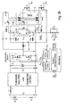
- Fig. 2a is a circuit realization of an electronic lamp ballast for AC operation of a fluorescent lamp LA after a first Embodiment of the present invention shown, which is a heating circuit with a Schustromregelnik HRK as described above with reference to Fig. 1 contains described.
- This in Fig. 2 sketched electronic lamp ballast thereby has an inverter half-bridge circuit DC / AC, consisting of two mutually connected in series, driven alternately with a fixed or adjustable frequency semiconductor power switches T 1 and T 2 , which serves for supplying voltage to the lamp LA AC voltage U WR provides.
- the frequency of this AC voltage can be controlled to adjust the lamp power.
- the inverter half-bridge DC / AC is supplied via a storage capacitor C 1 with an AC line voltage U e 1 smoothed by a radio interference suppression filter TPF and power rectifier AC / DC and rectified as an intermediate circuit voltage U c 1 .
- the output port of the inverter half-bridge DC / AC formed from the connection node between the two controllable semiconductor power switches T 1 and T 2 and the ground node of the electronic ballast is connected via a series resonant circuit consisting of a resonance inductor L and a resonance capacitor C 2 and via an (optional) coupling capacitor C 3 for decoupling the DC voltage component of the lamp LA supplied supply voltage U WR connected, via which the individual coils W 1 and W 2 of the gas discharge charge lamp LA are supplied with heating energy.
- the intermediate circuit voltage U C 1 is in this case by an alternately performed switching on and off of the two semiconductor power switches T 1 and T 2 of the inverter half-bridge DC / AC in a high-frequency Converted AC voltage that is output from the inverter to the series resonant circuit.
- At least one of the two lamp filaments W 1 and W 2 is preheated or additionally heated before and / or after the ignition of the lamp to a specific predeterminable operating temperature.
- the in Fig. 2a illustrated electronic lamp ballast via one or as shown two separate heating circuits HzK 1 and HzK 2 , via which the two helical electrodes W 1 and W 2 are heated to a desired operating temperature ⁇ W.
- a primary side in the two respective heating circuits HzK 1 or 2 Hz integrated and fed via a further (optional) coupling capacitor C 4 with the inverter output voltage U WR heating transformer HzTr with a secondary winding or two galvanically separated secondary windings L s 1 and L s 2 serves to Provision of the heating energy required in preheating by inductive coupling.
- the secondary side is connected to the helical electrodes.
- the primary side of this heating transformer according to the invention consists of at least two, for example. Via a common ferrite magnetically coupled primary windings L p 1 and L p 2 , which are activated alternatively or additively. Depending on the activation, different heating power levels can thus be selected.
- One of the primary windings L p 1 is, for example, selectively connectable to the other primary winding via a controllable semiconductor power switch T 3 connected in series with a diode D 3 acting as a half-wave rectifier.
- the circuit breaker may be, for example, one of act a Schustromregelungs Rhein of the R & S module controlled field effect transistor, which can be switched by a corresponding control of its gate electrode in a low-resistance state (switching mode), whereupon the relevant primary winding L p 1 is switched on.
- the heating operation is preferably started, in particular during preheating with low heating power, and the heating power is increased when a measured value representing the coil temperature indicates an insufficient coil temperature.
- the semiconductor power switch T 3 is operated in a high-resistance state (blocking operation). The result is that only the power supplied via the primary winding Lp heating power P 2 H2 to the two filament electrodes W 1 and W 2 is transmitted.
- the relevant primary winding L p 1 of the heating transformer HzTr is switched on via the forward-biased semiconductor power switch T 3 (or switched over to this primary winding L p 1 , if it transmits a higher heating power).
- the heating power P H 2 supplied to the helical electrodes W 1 and W 2 is increased by the amount of power P H 1 transmittable via this primary winding, or the higher heating power of the other primary winding is transmitted.
- the traversed by a part of the helical current I W2 measuring resistor R M is connected at one end to the helical electrode W 2 and at another end to the ground node.
- a to the measuring resistor R 2 connected in parallel with series circuit of two oppositely poled Zener diodes D 1 and D 2 serves to limit the voltage dropping across the measuring resistor R 2 measurement voltage U M.
- Fig. 2b is an electronic lamp ballast for AC operation of a fluorescent lamp according to a second embodiment of the present invention, which is opposite to the in Fig. 2a differs in that instead of a heating transformer HzTr with two each via a common ferrite core magnetically coupled, galvanically isolated primary ( L p 1 , L p 2 ) and secondary windings ( L s 1 , L s 2 ) a for the provision of heating energy the coil electrodes W 1 and W 2 of the lamp LA serving power transformer HzTr 'is used, the primary side consists of two parallel to each other connected to the associated secondary side via output taps connected autotransformer windings L p 1 ' and L p 2 ' , respectively a controllable semiconductor power switch T 3 and T 4 are individually or combined switchable.
- a heating transformer HzTr with two each via a common ferrite core magnetically coupled, galvanically isolated primary ( L p 1 , L p 2 ) and secondary windings ( L
- the secondary side of the power transformer HzTr 'in consists of two integrated into the two respective load circuits LK 1 and LK 2 , to the lamp filaments W 1 and W 2 in Series connected autotransformer windings L s 1 'and L s 2 ', so that results for each of the two consisting of a pair of primary and a secondary side autotransformer winding part transformer predetermined by the winding ratios of the individual autotransformer windings fixed voltage translation ratio , About a to the aforementioned parallel connection of the two switchable by the semiconductor power switches T 3 and T 4 primary side autotransformer windings L p 1 'and Lp 2 ' of the power transformer HzTr 'in series further semiconductor power switch T 5 , both heating circuits HzK 1 and HzK 2 are interrupted together, whereby the Bankwoodsmakersen the two lamp filaments W 1 and W 2 are turned off at the same time.
- an adjustable capacitor C 6 or C connected in series to the lamp filaments W 1 and W 2 and the individual secondary-side autotransformer windings L s 1 'and L s 2 ' can be connected 7 may be contained, via which the impedances of the respective load circuits and thus the characteristics of the current flowing through the respective lamp filaments helix currents I W 1 and I W 2 can be changed.
- a current-time diagram is shown, which is the temporal course of the current flowing through helical electrode W 1 preheat current I H 1 in forward mode or in blocking operation of the one of the two primary-side windings L p 1 and L p 2 of the heating transformer used HzTr controllable Semiconductor circuit breaker T 3 shows.
- the winding ratios ü 1 : 1 and ü 2 : 1 of the transformer windings can be set so that when switching through T 3 after the transient has subsided a preheating I H 1 sets, the peak value, for example, is almost twice as large Peak value of the pre-heating current I H 1 occurring in the blocking operation of T 3 .
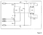
- Fig. 4 shows another embodiment of the present invention, in which a tap (center tap) is provided between the two ends of the inductance forming the primary side.
- a tap center tap
- the detection of the spiral temperature can indirectly, for example, on the primary side, namely on the in FIG. 4 apparent resistance R mp done.
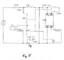
- Fig. 5 shows a further embodiment of the present invention, in which two primary windings Lph1, Lph2 are connected in series with each other.
- the in Fig. 5 shown heating transformer consists of two primary-side windings Lph1, Lph2 and two secondary windings Lh1, Lh2 coupled thereto.
- the two secondary-side windings Lh1, Lh2 of the heating transformer are respectively connected to the heating coil terminals P1, P2 of the one lamp electrode and the heating coil terminals P3, P4 of the second lamp electrode.
- a controllable heating switch S2opt is connected to a terminal of a primary-side winding Lph1 and to ground. This results in a series connection of the two primary-side windings Lph1, Lph2 of the heating transformer and the controllable switch S2opt.
- winding Lph1 is not connected to ground. Accordingly, no heating energy is transmitted to the helical electrodes P1, P2 via the secondary-side winding Lh1 coupled to the primary-side winding Lph1.
- the switches S1, S2opt are advantageously designed as AC switches, for example as mosfet switches in a rectifier bridge or in conjunction with the decoupling capacitor Cshortopt.
- the primary-side winding Lph1 of the heating transformer is connected directly to ground, ie the switch S2opt is not provided.
- This Einschaltertine can therefore provide two levels of performance with appropriate control of the switch S1, namely on both or only one primary winding.
- further primary windings are connected in series with the already mentioned primary windings Lph1, Lph2 so that selectively more than two or three different power levels can be provided (further switches are necessary in that case).
- the circuit arrangement according to the invention is integrated together with a spiral detection function in an electronic ballast.
- the Wendeldetetation is a known function, which can be realized for example via a measuring resistor R M , see for example FIG. 2a ,
- the thus detected filament current can be included in a control device to regulate according to the transmitted to the lamp heating power. For example, a low value of the filament current will cause more primary windings Lph1, Lph2 to transmit heating power via the switches S1, S2opt.
- switches S1, S2opt and primary windings Lph1, Lph2 must be provided.
- two different coil types are arranged with, for example, different coil resistors.
- an electronic ballast for very low dimming levels can increase the heating power.
- the primary side according to the invention is designed to selectively provide two and preferably three or more different power levels.
- the heating power switching is relatively simple, since it can be done by means of the combination of the MOSFET M1 with the diode D1, so that the control can be preferably without driver block directly, for example, by a microcontroller.
Abstract
Description
Die vorliegende Erfindung betrifft ein elektronisches Lampenvorschaltgerät (EVG) zum Betrieb einer oder mehrerer Leuchtstofflampen, das über eine integrierte Heizschaltung zum Beheizen von Wendelelektroden mindestens einer an das EVG angeschlossenen Leuchtstofflampe verfügt.The present invention relates to an electronic ballast (EBG) for operating one or more fluorescent lamps, which has an integrated heating circuit for heating coil electrodes of at least one fluorescent lamp connected to the ECG.
Ein elektronisches Lampenvorschaltgerät für Leuchtstofflampen mit beheizbaren Wendelelektroden ist beispielsweise in
In
Ein weiteres elektronisches Lampenvorschaltgerät mit einem integrierten Heizkreis zum Vorheizen der Wendelelektroden mindestens einer an das EVG angeschlossenen wechselstrombetriebenen Leuchtstofflampe ist in
Ein weiteres elektronisches Lampenvorschaltgerät sowie ein zugehöriges Verfahren zum Vorheizen und Zünden einer Leuchtstofflampe sind in
Ausgehend von dem vorstehend genannten Stand der Technik, ist die vorliegende Erfindung der Aufgabe gewidmet, eine anpassbare Heizschaltung bereitzustellen.Based on the above-mentioned prior art, the present invention is dedicated to providing an adaptable heating circuit.
Diese Aufgabe wird erfindungsgemäß durch die Merkmale der unabhängigen Patentansprüche gelöst. Ausführungsbeispiele, die den der Erfindung zugrunde liegende Grundgedanken in vorteilhafter Weise weiterbilden, sind in den abhängigen Patentansprüchen definiert.This object is achieved by the features of the independent claims. Embodiments that further develop the basic idea underlying the invention in an advantageous manner are defined in the dependent claims.
Die Aufgabe wird bspw. durch eine zum Beheizen von Wendelelektroden von Leuchtstofflampen vorgesehene Schaltung gemäß Anspruch 1 gelöst, welche einen Heiztransformator aufweist, dessen Sekundärseite mit wenigstens einer Wendelelektrode verbunden ist und der eine mit dieser Sekundärseite magnetisch gekoppelte, mit Spannung versorgte Primärseite aufweist. Dabei ist die Primärseite zur Bereitstellung unterschiedlicher, durch den Heiztransformator übertragener Heizleistungen ausgelegt.The object is achieved, for example, by a circuit provided for heating filament electrodes of fluorescent lamps according to
Durch Massnahmen seitens der Primärseite kann somit die Heizschaltung auch im Betrieb an unterschiedliche Bedingungen bzgl. des Betriebszustands, des Dimmzustands, anliegender Eingangsspannungen und/oder unterschiedliche Lampentypen angepasst werden.As a result of measures taken by the primary side, the heating circuit can thus also be adapted during operation to different conditions with regard to the operating state, the dimming state, applied input voltages and / or different lamp types.
Dabei können an der Primärseite erfindungsgemäß mehrere magnetisch gekoppelte Spulen vorgesehen sein, welche alternativ oder kombiniert aktivierbar sind. Auch eine Ausgestaltung in Form eines Spartransformators ist möglich.In this case, according to the invention a plurality of magnetically coupled coils can be provided on the primary side, which can be activated alternatively or in combination. An embodiment in the form of an autotransformer is possible.
Alternativ bezieht sich die vorliegende Erfindung auf eine zum Beheizen von Wendelelektroden von Leuchtstofflampen vorgesehene Schaltung, die einen Heiztransformator aufweist, dessen Sekundärseite mit wenigstens einer Wendelelektrode verbunden ist und der eine mit dieser Sekundärseite magnetisch gekoppelte, mit Spannung versorgte Primärseite aufweist. Dabei sind an der Primärseite mehrere magnetisch gekoppelte Spulen vorgesehen, die alternativ oder kombiniert aktivierbar sind, um unterschiedliche Heizleistungen bereitzustellen.Alternatively, the present invention relates to a circuit provided for heating filament electrodes of fluorescent lamps, comprising a heating transformer whose secondary side is connected to at least one filament electrode and a primary side which is magnetically coupled to this secondary side and supplied with voltage having. In this case, a plurality of magnetically coupled coils are provided on the primary side, which can be activated alternatively or in combination to provide different heating powers.
Die Primärseite des Heiztransformators wird hierbei über den Mittenpunkt einer Wechselrichter-Halbbrückenschaltung mit einer Wechselspannung zum Betrieb einer an die Schaltung angeschlossenen Lampe versorgt.The primary side of the heating transformer is in this case supplied via the midpoint of an inverter half-bridge circuit with an AC voltage for operating a lamp connected to the circuit.
Die vorliegende Erfindung betrifft ferner ein Betriebsgerät für Leuchtstofflampen, welches eine Schaltung gemäß einer der beiden vorstehend beschriebenen Alternativen aufweist. Das Betriebsgerät kann dabei eine Steuerschaltung umfassen, die die zu den Wendelelektroden übertragene Heizleistung abhängig vom Betriebs- und/oder Dimmzustand einer angeschlossenen Lampe einstellt. Darüber hinaus kann das Betriebsgerät auch eine Steuerschaltung aufweisen, die die Heizleistung abhängig vom Typ einer angeschlossenen Lampe einstellt und/oder abhängig von der Erfassung eines Parameters einstellt, der die Betriebstemperatur der Wendelelektroden wiedergibt.The present invention further relates to an operating device for fluorescent lamps, which has a circuit according to one of the two alternatives described above. The operating device may include a control circuit which adjusts the heat output transferred to the helical electrodes depending on the operating and / or dimming state of a connected lamp. In addition, the operating device may also have a control circuit which adjusts the heating power depending on the type of a connected lamp and / or adjusts depending on the detection of a parameter representing the operating temperature of the helical electrodes.
Dabei kann das Betriebsgerät auch zum Dimmen einer oder mehrerer an einen Ausgangsanschluss des Betriebsgeräts angeschlossener Leuchtstofflampen ausgelegt sein.In this case, the operating device can also be designed to dim one or more fluorescent lamps connected to an output terminal of the operating device.
Außerdem bezieht sich die Erfindung auf ein Verfahren zum Beheizen von Wendelelektroden von Leuchtstofflampen mit Hilfe eines Heiztransformators, dessen Sekundärseite mit wenigstens einer Wendelelektrode verbunden ist und der eine magnetisch mit dieser Sekundärseite gekoppelte, mit Spannung versorgte Primärseite aufweist. Das Verfahren weist dabei den Schritt der Einstellung einer von mehreren Heizleistungsstufen durch selektive Aktivierung der Primärseite des Heiztransformators auf.In addition, the invention relates to a method for heating filament electrodes of fluorescent lamps by means of a heating transformer whose secondary side is connected to at least one coil electrode and which has a magnetically coupled to this secondary side, supplied with voltage primary side. The method comprises the step of adjusting one of a plurality of heating power stages by selective activation of the primary side of the heating transformer on.
Alternativ ist die vorliegende Erfindung einem Verfahren zum Heizen von Wendelelektroden von Leuchtstofflampen mit Hilfe eines Heiztransformators gewidmet, dessen Sekundärseite mit wenigstens einer Wendelelektrode verbunden ist und der eine magnetisch mit dieser Sekundärseite gekoppelte, mit Spannung versorgte Primärseite aufweist. Das Verfahren weist dabei den Schritt der Einstellung einer von mehreren Heizleistungsstufen durch selektive Aktivierung einer oder mehrerer magnetisch gekoppelter, die Primärseite des Heiztransformators bildender Spulen auf.Alternatively, the present invention is directed to a method of heating filament electrodes of fluorescent lamps by means of a heating transformer whose secondary side is connected to at least one filament electrode and which has a primed primary side magnetically coupled to this secondary side. The method comprises the step of adjusting one of a plurality of heating power stages by selectively activating one or more magnetically coupled coils forming the primary side of the heating transformer.
Dabei kann vorgesehen sein, dass nach Einstellen der niedrigsten Heizleistungsstufe ein Parameter erfasst wird, der die Wendeltemperatur wiedergibt. Falls die Wendeltemperatur noch nicht ausreichend ist, wird erfindungsgemäß eine höhere Heizleistungsstufe ausgewählt. Die aktuelle Heizleistungsstufe kann darüber hinaus abhängig vom Betriebszustand und/oder vom Dimmzustand der an die vorgenannte Schaltung angeschlossenen Lampe gewählt werden oder abhängig vom Typ der angeschlossenen Lampe.It can be provided that after setting the lowest heating power level, a parameter is detected, which reflects the spiral temperature. If the spiral temperature is still insufficient, a higher heat output level is selected according to the invention. The current Heizleistungsstufe may also be selected depending on the operating condition and / or the dimming state of the lamp connected to the aforementioned circuit or depending on the type of the connected lamp.
Ferner bezieht sich die vorliegende Erfindung auch auf eine elektronische Steuereinheit, die zur Unterstützung eines der oben beschriebenen Verfahrens ausgelegt ist.Furthermore, the present invention also relates to an electronic control unit designed to support one of the methods described above.
Weitere Eigenschaften, Vorteile und Zweckmäßigkeiten der vorliegenden Erfindung werden nunmehr, Bezug nehmend auf die beigefügten Zeichnungen, anhand einer detaillierten Beschreibung der Ausführungsbeispiele vorliegender Erfindung erläutert. Es zeigt
- Fig. 1
- eine Prinzipskizze eines elektronischen Lampenvorschaltgeräts zum Betrieb einer Leuchtstofflampe mit einem Heizstromregelkreis zur Regelung der zum Vorheizen mindestens einer der beiden Lampenwendeln erforderlichen Heizleistung,
- Fig. 2
- ein elektronisches Lampenvorschaltgerät zum Wechselstrombetrieb einer Leuchtstofflampe nach einem ersten Ausführungsbeispiel der vorliegenden Erfindung mit einem zur Bereitstellung von Heizenergie an die Wendelelektroden der Lampe dienenden Heiztransformator,
- Fig. 3
- ein Strom-Zeit-Diagramm, das den zeitlichen Verlauf des durch eine der Wendelelektroden fließenden Vorheizstroms im Durchlassbetrieb bzw. im Sperrbetrieb des zum Zuschalten eines der beiden primärseitigen Wicklungen des Heiztransformators verwendeten steuerbaren Halbleiter-Leistungsschalter,
- Fig. 4
- ein weiteres Ausführungsbeispiel der Erfindung,
- Fig. 5
- ein weiteres Ausführungsbeispiel gemäß der vorliegenden Erfindung, und
- Fig. 6
- ein weiteres Ausführungsbeispiel gemäß der vorliegenden Erfindung.
- Fig. 1
- a schematic diagram of an electronic lamp ballast for operating a fluorescent lamp with a Heizstromregelkreis for controlling the heat required for preheating at least one of the two lamp filaments,
- Fig. 2
- an electronic lamp ballast for AC operation of a fluorescent lamp according to a first embodiment of the present invention having a heating transformer for supplying heating energy to the filament electrodes of the lamp,
- Fig. 3
- a current-time diagram showing the time course of the preheating current flowing through one of the helical electrodes in the forward operation or in the blocking operation of the controllable semiconductor power switch used for connecting one of the two primary-side windings of the heating transformer,
- Fig. 4
- a further embodiment of the invention,
- Fig. 5
- another embodiment according to the present invention, and
- Fig. 6
- another embodiment according to the present invention.
Im Folgenden werden die Ausführungsbeispiele der vorliegenden Erfindung unter Bezugnahme auf
In
Die Heizschaltung weist dabei einen Heiztransformator HzTr' auf, dessen Sekundärseite L s1', L s2 ', mit wenigstens einer Wendelelektrode W1, W2 verbunden ist. Der Heiztransformator weist weiterhin eine mit dieser Sekundärseite L s1', L s2' magnetisch gekoppelte Primärseite (Lp 1 ', Lp 2') auf.The heating circuit in this case has a heating transformer HzTr 'whose secondary side L s 1' , L s 2 ' , with at least one helical electrode W 1 , W 2 is connected. The heating transformer further has a secondary side L s 1 ', L s 2 ' magnetically coupled primary side ( Lp 1 ' , Lp 2' ) on.
Die Heizschaltung kann schliesslich auch einen Heizstromregelkreises HRK aufweisen.Finally, the heating circuit can also have a heating current control circuit HRK.
Im Vorwärtszweig dieses Heizstromregelkreises HRK befindet sich wenigstens ein Leistungsstellglied, welches zur Einstellung der übertragenen Heizleistung durch Zugriff auf die Primärseite des Heiztransformators dient.In the forward branch of this Heizstromregelkreises HRK is at least one power actuator, which serves to adjust the transmitted heat output by access to the primary side of the heating transformer.
Die Einstellung der durch den Heiztransformators übertragenen Heizleistung kann bspw. in Abhängigkeit von einer Stellgröße StG erfolgen, die von einem Datenausgang Data OUT einer digitalen Regelungs- und Steuerungseinrichtung (R&S-Modul) geliefert wird. Der Regelungs- und Steuerungseinrichtung wird dabei über einen Dateneingang Data IN1 ein Messwert einer über einen Lastkreis des elektronischen Lampenvorschaltgeräts abgegriffenen Regelgröße RG (Istwert) zugeführt, in welchem sich eine der beiden Lampenwendeln W1 bzw. W2 befindet. Der Messwert gibt indirekt oder direkt die Wendeltemperatur wieder.The setting of the heating power transmitted by the heating transformer may, for example, in dependence on a manipulated variable StG, which is supplied by a data output Data OUT a digital control and regulating device (R & S module). In this case, the control and regulating device is supplied via a data input Data IN 1 with a measured value of a controlled variable RG (actual value) tapped via a load circuit of the electronic lamp ballast, in which one of the two lamp filaments W 1 and W 2 is located. Of the Measured value indirectly or directly reflects the spiral temperature.
Bei diesem Messwert kann es sich zum Beispiel um eine Spannung U M handeln, die zu dem durch eine der beiden Lampenwendeln (W2) fließenden Wendelstrom I W2 proportional ist und damit eine Aussage über den temperaturabhängigen Wirkwiderstand R W2 (ϑ W2) der betreffenden Lampenwendel W2 und deren Betriebstemperatur ϑ W2 liefert.This measured value may be, for example, a voltage U M which is proportional to the filament current I W2 flowing through one of the two lamp filaments (W 2 ) and thus a statement about the temperature-dependent effective resistance R W 2 ( θ W 2 ) relevant lamp filament W 2 and the operating temperature θ W 2 supplies.
Die Regelungs- und Steuerungseinrichtung regelt die Stellgröße StG hierbei abhängig von dem an dem Dateneingang Data IN1 anliegenden Messwert der Regelgröße RG sowie einer Führungsgröße FG (Sollwert) für die im Heizbetrieb an mindestens eine der beiden Lampenwendeln W1 bzw. W2 zu übertragende Heizleistung P H1 bzw. P H2.The control and regulating device controls the manipulated variable StG in this case as a function of the measured value of the controlled variable RG present at the data input Data IN 1 and a command variable FG (setpoint value) for the heating power to be transmitted in heating operation to at least one of the two lamp filaments W 1 and W 2 P H 1 or P H 2 .
Der Sollwert kann dabei bspw. von folgenden Parametern abhängen (nicht-abschliessende Aufzählung), die jeweils direkt oder indirekt erfasst und der Regelungs- und Steuerungseinrichtung zugeführt werden können:
- Betriebszustand der Lampe (bspw. Vorheizen oder Zuheizen während des Brennbetriebs),
- Dimmzustand der Lampe (stärkeres Heizen bei Betrieb bei niedrigen Dimmwerten),
- Höhe der anliegenden Eingangsspannung, und/oder
- Lampentyp (ggf. automatische Lampentyperkennung bspw. Über den Wendelwiederstand oder andere elektr. Eigenschaften der Lampe).
- Operating status of the lamp (eg preheating or heating during combustion),
- Dimming status of the lamp (higher heating when operating at low dimming values),
- Amount of applied input voltage, and / or
- Lamp type (possibly automatic lamp type detection eg via the coil resistance or other electrical properties of the lamp).
In
Das in
Der Wechselrichterhalbbrücke DC/AC wird dabei über einen Speicherkondensator C 1 eine von einem Funkentstörfilter TPF und Netzgleichrichter AC/DC geglättete und gleichgerichtete Netzwechselspannung U e1 als Zwischenkreisspannung U c1 zugeführt. Das aus dem Verbindungsknoten zwischen den beiden steuerbaren Halbleiter-Leistungsschalter T1 und T2 und dem Masseknoten des EVGs gebildete Ausgangstor der Wechselrichterhalbbrücke DC/AC ist über einen aus einer Resonanzinduktivität L und einer Resonanzkapazität C2 bestehenden Serienresonanzkreis sowie über einen (optionalen) Koppelkondensator C 3 zur Entkopplung des Gleichspannungsanteils der der Lampe LA zugeführten Versorgungsspannung U WR verbunden, über die die einzelnen Wendeln W1 und W2 der Gasentladungsladungslampe LA mit Heizenergie versorgt werden.In this case, the inverter half-bridge DC / AC is supplied via a storage capacitor C 1 with an AC line voltage U e 1 smoothed by a radio interference suppression filter TPF and power rectifier AC / DC and rectified as an intermediate circuit voltage U c 1 . The output port of the inverter half-bridge DC / AC formed from the connection node between the two controllable semiconductor power switches T 1 and T 2 and the ground node of the electronic ballast is connected via a series resonant circuit consisting of a resonance inductor L and a resonance capacitor C 2 and via an (optional) coupling capacitor C 3 for decoupling the DC voltage component of the lamp LA supplied supply voltage U WR connected, via which the individual coils W 1 and W 2 of the gas discharge charge lamp LA are supplied with heating energy.
Die Zwischenkreisspannung U C1 wird dabei durch ein alternierend durchgeführtes Ein- und Ausschalten der beiden Halbleiter-Leistungsschalter T1 und T2 der Wechselrichterhalbbrücke DC/AC in eine hochfrequente Wechselspannung umgewandelt, die von dem Wechselrichter an den Serienresonanzkreis abgegeben wird.The intermediate circuit voltage U C 1 is in this case by an alternately performed switching on and off of the two semiconductor power switches T 1 and T 2 of the inverter half-bridge DC / AC in a high-frequency Converted AC voltage that is output from the inverter to the series resonant circuit.
Es ist vorgesehen, dass zumindest eine der beiden Lampenwendeln W1 und W2 vor und/oder nach dem Zünden der Lampe auf eine bestimmte vorgebbare Betriebstemperatur vorgeheizt bzw. zusätzlich beheizt wird. Zu diesem Zweck verfügt das in
Ein primärseitig in die beiden jeweiligen Heizkreise HzK1 bzw. HzK2 integrierter und über einen weiteren (optionalen) Koppelkondensator C 4 mit der Wechselrichterausgangsspannung U WR gespeister Heiztransformator HzTr mit einer Sekundärwicklung oder zwei galvanisch getrennten Sekundärwicklungen L s1 und L s2 dient dabei zur Bereitstellung der im Vorheizbetrieb erforderlichen Heizenergie durch induktive Einkopplung. Die Sekundärseite ist als mit den Wendelelektroden verbunden.A primary side in the two respective heating circuits HzK 1 or 2 Hz integrated and fed via a further (optional) coupling capacitor C 4 with the inverter output voltage U WR heating transformer HzTr with a secondary winding or two galvanically separated secondary windings L s 1 and L s 2 serves to Provision of the heating energy required in preheating by inductive coupling. The secondary side is connected to the helical electrodes.
Die Primärseite dieses Heiztransformators besteht erfindungsgemäß aus wenigstens zwei bspw. über einen gemeinsamen Ferritkern magnetisch gekoppelten Primärwicklungen L p1 und L p2, die alternativ oder additiv aktivierbar sind. Je nach Aktivierung können somit unterschiedliche Heizleistungsstufen gewählt werden.The primary side of this heating transformer according to the invention consists of at least two, for example. Via a common ferrite magnetically coupled primary windings L p 1 and L p 2 , which are activated alternatively or additively. Depending on the activation, different heating power levels can thus be selected.
Eine der Primärwicklungen L p1 ist bspw. über einen in Serie zu einer als Einweggleichrichter wirkenden Diode D3 geschalteten, steuerbaren Halbleiter-Leistungsschalter T3 selektiv zu der anderen Primärwicklung zuschaltbar. Bei dem Leistungsschalter kann es sich beispielsweise um einen von einer Heizstromregelungseinrichtung des R&S-Moduls angesteuerten Feldeffekttransistor handeln, der durch eine entsprechende Ansteuerung seiner Gate-Elektrode in einen niederohmigen Zustand geschaltet werden kann (Durchschaltbetrieb), woraufhin die betreffende Primärwicklung L p1 zugeschaltet wird.One of the primary windings L p 1 is, for example, selectively connectable to the other primary winding via a controllable semiconductor power switch T 3 connected in series with a diode D 3 acting as a half-wave rectifier. The circuit breaker may be, for example, one of act a Heizstromregelungseinrichtung of the R & S module controlled field effect transistor, which can be switched by a corresponding control of its gate electrode in a low-resistance state (switching mode), whereupon the relevant primary winding L p 1 is switched on.
Vorzugsweise wird der Heizbetrieb insbesondere beim Vorheizen mit niedriger Heizleistung begonnen und die Heizleistung erhöht, wenn ein die Wendeltemperatur wiedergebender Messwert eine unzureichende Wendeltemperatur anzeigt.The heating operation is preferably started, in particular during preheating with low heating power, and the heating power is increased when a measured value representing the coil temperature indicates an insufficient coil temperature.
Solange der durch Wendel W2 fließende, über die an einem Messwiderstand RM abfallende Spannung U M erfasste Wendelstrom I W2 einen der Heizstromregeleinrichtung über eine Referenzspannung U ref2 vorgebbaren, einen bestimmten Heißwiderstand der Wendelelektrode W2 und damit eine bestimmte Wendeltemperatur ϑ W2 repräsentierenden Schwellenwert nicht unterschreitet, wird der Halbleiter-Leistungsschalter T3 in einem hochohmigen Zustand betrieben (Sperrbetrieb). Die führt dazu, dass nur die über die Primärwicklung Lp2 zugeführte Heizleistung PH2 zu den beiden Wendelelektroden W1 und W2 übertragen wird.As long as the through spiral W 2 flowing, detected through the voltage dropping at a measuring resistor R M voltage U M helix current I W 2 one of the Heizstromregeleinrichtung via a reference voltage U ref 2 predeterminable, a certain heat resistance of the coil electrode W 2 and θ a given filament temperature W 2 Not falling below representing representative threshold, the semiconductor power switch T 3 is operated in a high-resistance state (blocking operation). The result is that only the power supplied via the primary winding Lp heating power P 2 H2 to the two filament electrodes W 1 and W 2 is transmitted.
Unterschreitet der Wendelstrom I W2 jedoch diesen Schwellenwert, wird die betreffende Primärwicklung L p1 des Heiztransformators HzTr über den auf Durchlassbetrieb umgeschalteten Halbleiter-Leistungsschalter T3 zugeschaltet (oder auf diese Primärwicklung L p1 umgeschaltet, falls diese eine höhere Heizleistung überträgt). Somit wird die den Wendelelektroden W1 und W2 zugeführte Heizleistung P H2 um den Betrag der über diese Primärwicklung übertragbaren Leistung P H1 erhöht bzw. es wird die höhere Heizleistung der anderen Primärwicklung übertragen.However, if the filament current I W 2 falls below this threshold value, the relevant primary winding L p 1 of the heating transformer HzTr is switched on via the forward-biased semiconductor power switch T 3 (or switched over to this primary winding L p 1 , if it transmits a higher heating power). Thus, the heating power P H 2 supplied to the helical electrodes W 1 and W 2 is increased by the amount of power P H 1 transmittable via this primary winding, or the higher heating power of the other primary winding is transmitted.
Es kann also abhängig von der erfassten Wendeltemperatur ϑ W2 zwischen verschiedenen vorzugsweise diskreten Heizleistungsstufen umgeschaltet werden, die z.B. im Vorheizbetrieb und/oder im Dimmbetrieb der Lampe LA benötigt werden.Thus, depending on the detected coil temperature θ W 2 , it is possible to switch between different, preferably discrete, heat output stages which are required, for example, in the preheat mode and / or in the dimming mode of the lamp LA.
Wie
In
Die Sekundärseite des Leistungsübertrager HzTr' besteht dabei ihrerseits aus zwei in die beiden jeweiligen Lastkreise LK1 bzw. LK2 integrierten, zu den Lampenwendeln W1 bzw. W2 in Serie geschalteten Spartransformator-Wicklungen L s1' und L s2', so dass sich für jeden der beiden aus je einem Paar einer primär- und einer sekundärseitigen Spartransformator-Wicklung bestehenden Teilübertrager ein durch die Wicklungsverhältnisse der einzelnen Spartransformator-Wicklungen vorgebbares festes Spannungsübersetzungsverhältnis ergibt. Über einen zu der vorgenannten Parallelschaltung der beiden durch die Halbleiter-Leistungsschalter T3 bzw. T4 zuschaltbaren primärseitigen Spartransformator-Wicklungen L p1' und Lp 2' des Leistungsübertragers HzTr' in Serie geschalteten weiteren Halbleiter-Leistungsschalter T5, können beide Heizkreise HzK1 und HzK2 gemeinsam unterbrochen werden, wodurch die Heizspannungsversorgungen der beiden Lampenwendeln W1 und W2 gleichzeitig abgeschaltet werden.The secondary side of the power transformer HzTr 'in turn consists of two integrated into the two respective load circuits LK 1 and LK 2 , to the lamp filaments W 1 and W 2 in Series connected autotransformer windings L s 1 'and L s 2 ', so that results for each of the two consisting of a pair of primary and a secondary side autotransformer winding part transformer predetermined by the winding ratios of the individual autotransformer windings fixed voltage translation ratio , About a to the aforementioned parallel connection of the two switchable by the semiconductor power switches T 3 and T 4 primary side autotransformer windings L p 1 'and Lp 2 ' of the power transformer HzTr 'in series further semiconductor power switch T 5 , both heating circuits HzK 1 and HzK 2 are interrupted together, whereby the Heizspannungsversorgungen the two lamp filaments W 1 and W 2 are turned off at the same time.
Optional kann in jedem der beiden Lastkreise LK1 bzw. LK2 auch ein zu den Lampenwendeln W1 bzw. W2 und den einzelnen sekundärseitigen Spartransformator-Wicklungen L s1' und L s2' in Serie geschalteter einstellbarer Kondensator C6 bzw. C7 enthalten sein, über den die Impedanzen der jeweiligen Lastkreise und damit die Kennlinien der durch die jeweiligen Lampenwendeln fließenden Wendelströme I W1 bzw. I W2 verändert werden können.Optionally, in each of the two load circuits LK 1 and LK 2 , an adjustable capacitor C 6 or C connected in series to the lamp filaments W 1 and W 2 and the individual secondary-side autotransformer windings L s 1 'and L s 2 ' can be connected 7 may be contained, via which the impedances of the respective load circuits and thus the characteristics of the current flowing through the respective lamp filaments helix currents I W 1 and I W 2 can be changed.
In
Die Erfassung der Wendeltemperatur kann indirekt beispielsweise auch auf der Primärseite, nämlich über den in
Das Umschalten zwischen Heizleistungsstufen erfolgt auch beim Ausführungsbeispiel von
Der in
Ein steuerbarer Heizschalter S2opt ist mit einem Anschluss einer primärseitigen Wicklung Lph1 sowie an Masse angeschlossen. Somit ergibt sich eine Serienschaltung aus den beiden primärseitigen Wicklungen Lph1, Lph2 des Heiztransformators und dem steuerbaren Schalter S2opt.A controllable heating switch S2opt is connected to a terminal of a primary-side winding Lph1 and to ground. This results in a series connection of the two primary-side windings Lph1, Lph2 of the heating transformer and the controllable switch S2opt.
Parallel zum Schalter S2opt und zu der primärseitigen Wicklung Lph1 ist eine Serienschaltung mit einem steuerbaren Schalter S1 und einen Kondensator bzw. Entkoppelkondensator Cshortopt angeschlossen.Parallel to the switch S2opt and the primary-side winding Lph1 a series circuit with a controllable switch S1 and a capacitor or decoupling capacitor Cshortopt is connected.
Sobald einer der beiden Schalter S1, S2opt eingeschaltet ist, fließt Strom durch die primärseitige Wicklung Lph2, so dass den Wendeln P3, P4 eine entsprechende Heizleistung übertragen wird.As soon as one of the two switches S1, S2opt is switched on, current flows through the primary-side winding Lph2, so that a corresponding heating power is transmitted to the coils P3, P4.
Ist der Schalter S2opt ausgeschaltet (Sperrbetrieb), so ist die Wicklung Lph1 nicht mit Masse verbunden. Demnach wird auch über die mit der primärseitigen Wicklung Lph1 gekoppelten sekundärseitige Wicklung Lh1 keine Heizenergie an die Wendelelektroden P1, P2 übertragen.If switch S2opt is switched off (blocking operation), then winding Lph1 is not connected to ground. Accordingly, no heating energy is transmitted to the helical electrodes P1, P2 via the secondary-side winding Lh1 coupled to the primary-side winding Lph1.
Es lassen sich somit drei verschiedene Leistungsstufen einstellen. Das Ausschalten der Schalter S1, S2opt verhindert jegliche Energieübertragung. Dagegen wird eine erste durch die Wicklungen Lph2, Lh2 bestimmte Leistung mit dem eingeschalteten Schalter S1 erreicht. Das Einschalten des Schalters S2opt bei gleichzeitigem Abschalten des Schalters S1 bewirkt schließlich eine zweite Leistungsstufe, die der maximalen Leistung des Heiztransformator entspricht.It is thus possible to set three different power levels. Turning off the switches S1, S2opt prevents any energy transfer. By contrast, a first power determined by the windings Lph2, Lh2 is achieved with the switched-on switch S1. The switching on of the switch S2opt with simultaneous switching off of the switch S1 finally causes a second power stage, which corresponds to the maximum power of the heating transformer.
Die Schalter S1, S2opt sind vorteilhafterweise als Wechselstromschalter ausgeführt, wie zum Beispiel als Mosfet-Schalter in einer Gleichrichterbrücke oder in Verbindung mit dem Entkoppelkondensator Cshortopt.The switches S1, S2opt are advantageously designed as AC switches, for example as mosfet switches in a rectifier bridge or in conjunction with the decoupling capacitor Cshortopt.
Gemäß der in Zusammenhang mit
Diese Einschaltervariante kann deshalb bei entsprechender Steuerung des Schalters S1 zwei Leistungsstufen bereitstellen, nämlich über beide oder nur eine Primärwicklung.This Einschaltervariante can therefore provide two levels of performance with appropriate control of the switch S1, namely on both or only one primary winding.
Ist der Schalter S1 eingeschaltet, so ist die primärseitige Wicklung Lph1 kurzgeschlossen, so dass nur an die Wendelelektroden P3, P4 der Lampe über die Wicklungen Lph2, Lh2 Heizleistung übertragen werden kann.If the switch S1 is turned on, the primary-side winding Lph1 is short-circuited, so that heating power can be transmitted only to the filament electrodes P3, P4 of the lamp via the windings Lph2, Lh2.
Ein Abschalten des steuerbaren Schalters S1 führt dazu, dass die über die Primärwicklung Lph1, Lph2 zugeführte Heizleistung zu den beiden Wendelelektroden p1, p2, und p3, p4 übertragen wird.Switching off the controllable switch S1 results in that the heating power supplied via the primary winding Lph1, Lph2 is transmitted to the two helical electrodes p1, p2, and p3, p4.
Nach weiteren Ausführungsformen der Erfindung werden weitere Primärwicklungen mit den bereits erwähnten Primärwicklungen Lph1, Lph2 in Serie geschaltet, so dass selektiv mehr als zwei oder drei unterschiedliche Leistungsstufen bereitgestellt werden können (weitere Schalter sind in dem Fall notwendig).According to further embodiments of the invention further primary windings are connected in series with the already mentioned primary windings Lph1, Lph2 so that selectively more than two or three different power levels can be provided (further switches are necessary in that case).
Vorzugsweise wird die erfindungsgemäße Schaltungsanordnung zusammen mit einer Wendeldetektionsfunktion in einem elektronischen Vorschaltgerät integriert. Die Wendeldetektion ist eine an sich bekannte Funktion, die beispielsweise über einen Meßwiderstand RM realisiert werden kann, siehe beispielsweise
Der somit erfasste Wendelstrom kann in einer Regeleinrichtung einbezogen werden, um entsprechend die an die Lampe übertragene Heizleistung zu regeln. Ein niedriger Wert des Wendelstroms wird beispielsweise dazu führen, dass über die Schalter S1, S2 opt mehr Primärwicklungen Lph1, Lph2 Heizleistung übertragen.The thus detected filament current can be included in a control device to regulate according to the transmitted to the lamp heating power. For example, a low value of the filament current will cause more primary windings Lph1, Lph2 to transmit heating power via the switches S1, S2opt.
Im Gegensatz dazu kann ein zu hoher Wert des Wendelstroms die Schalter S1, S2opt derart regeln, dass weniger Heizleistung über die Primärwicklungen Lph1, Lph2 übertragen wird.In contrast, too high a value of the filament current can control the switches S1, S2opt so that less heating power is transmitted via the primary windings Lph1, Lph2.
Je nach Anzahl der gewünschten Leistungsstufen muss eine entsprechende Anzahl von Schaltern S1, S2opt und Primärwicklungen Lph1, Lph2 vorgesehen werden. Vorzugsweise sind zwei verschiedene Wendeltypen mit beispielsweise unterschiedlichen Wendelwiderständen angeordnet.Depending on the number of desired power levels, a corresponding number of switches S1, S2opt and primary windings Lph1, Lph2 must be provided. Preferably, two different coil types are arranged with, for example, different coil resistors.
Alternativ dazu kann mit dieser Erfindung auch ein elektronisches Vorschaltgerät für sehr niedrige Dimmlevel die Heizleistung erhöhen.Alternatively, with this invention, an electronic ballast for very low dimming levels can increase the heating power.
Insgesamt ist also festzuhalten, dass die Primärseite erfindungsgemäß dazu ausgebildet ist, selektiv zwei und bevorzugt drei oder mehr unterschiedliche Leistungsstufen bereitzustellen.Overall, therefore, it should be noted that the primary side according to the invention is designed to selectively provide two and preferably three or more different power levels.
Erfindungsgemäß ist die Heizungsleistungsumschaltung verhältnismäßig einfach, da sie mittels der Kombination des MOSFETS M1 mit der Diode D1 erfolgen kann, so dass die Ansteuerung bevorzugt ohne Treiberbaustein direkt beispielsweise durch einen Mikrocontroller erfolgen kann.According to the invention, the heating power switching is relatively simple, since it can be done by means of the combination of the MOSFET M1 with the diode D1, so that the control can be preferably without driver block directly, for example, by a microcontroller.
Durch die Erfindung lassen sich u.a. die folgenden Vorteile erzielen:
- Die Heizleistung kann unabhängig von der Busspannung und der Arbeitsfrequenz des Wechselrichters sein, wenn die Versorgung der Primärseite des Heiztransformators bspw. über eine Abgriff der Mittenpunktspannung des Wechselrichters erfolgt.
- Diese ist natürlich insbesondere dann ein Vorteil, wenn der Wechselrichter mit konstanter Frequenz betrieben wird.
- Das Umschalten der Primärseite des Heiztransformators ist verhältnismässig einfach im Vergleich z.B. zu einem hochfrequent getakteten Schalter auf der Primärseite.
- The heating power can be independent of the bus voltage and the operating frequency of the inverter, if the supply of the primary side of the heating transformer, for example. Via a tap of the mid-point voltage of the inverter takes place.
- This is of course an advantage in particular if the inverter is operated at a constant frequency.
- The switching of the primary side of the heating transformer is relatively simple in comparison, for example, to a high-frequency clocked switch on the primary side.
Claims (13)
- Circuit for heating filament electrodes (W1, W2) of fluorescent lamps (LA),
having a heating transformer (HzTr), the secondary side (L s1, L s2) of which is connected to at least one filament electrode (W1 and/or W2) and which has a primary side (Lp1 , L p2) magnetically coupled to this secondary side (L s1, L s2) and supplied with voltage ( U WR ), characterised in that provided on the primary side (Lp1, Lp2) there are a plurality of magnetically coupled coils which can be activated alternatively or in a combined manner in order to provide different heating powers (PH1, PH2, PH1 + PH2). - Circuit according to claim 1,
in which the plurality of magnetically coupled coils are formed by an inductance with an economy transformer central tap. - Circuit according to claim 1,
wherein the different heating powers can be provided by way of a semiconductor component of the primary side. - Circuit according to one of the preceding claims,
wherein the voltage supply of the primary side (L p1 , L p2 ) is effected by way of the central point of an inverter half-bridge circuit (DC/AC) that provides an alternating voltage (U WR) for the operation of a connected lamp (LA). - Operating unit for fluorescent lamps,
having a circuit according to one of the preceding claims. - Operating unit according to claim 5,
having a control circuit (R&S-module) that sets the heating power (PH1, PH2, PH1 + PH2) as a function of the operating and/or dimming state of a connected lamp (LA). - Operating unit according to claim 5 or 6,
having a control circuit (R&S-module) that sets the heating power (PH1, PH2, PH1 + PH2) as a function of the type of lamp (LA) connected. - Operating unit according to claim 5 or 6,
having a control circuit (R&S-module) that sets the heating power (PH1, PH2, PH1 + PH2) as a function of the acquisition of a parameter (I w1, I w2) that reproduces the filament temperature (θ w1 , θ w2 ), the applied input voltage, the operating state and/or the lamp type. - Method for heating filament electrodes (W1, W2) of fluorescent lamps (LA) with the aid of a heating transformer (HzTr), the secondary side (Ls1, Ls2) of which is connected to at least one filament electrode (W1 and/or W2) and which has a primary side (Lp1, Lp2 ) magnetically coupled to this secondary side (Ls1, Ls2 ) and supplied with voltage ( U WR ), characterised by and having the step of setting one of a plurality of heating-power stages (PH1, PH2, PH1 + PH2 ) by means of selective activation of one or a plurality of magnetically coupled coils that form the primary side (Lp1, Lp2 ) of the heating transformer (HzTr).
- Method according to claim 9,
having the following steps:- setting the lowest heating-power stage (PH1, PH2 ),- acquiring a parameter (Iw1, Iw2 ) that reproduces the filament temperature (θ w1, θ w2), and- selecting a higher heating-power stage (PH1 + PH2 ) if the filament temperature (θ w1 , θ w2 ) is not yet sufficient.11. Method according to one of claims 9 or 10,
wherein the current heating-power stage (PH1, PH2, PH1 + PH2 ) is selected as a function of the operating state, the level of the applied input voltage, the lamp type and/or dimming state of the connected lamp (LA). 12. Method according to one of claims 9 to 11,
wherein the current heating-power stage (PH1, PH2, PH1 + PH2 ) is selected as a function of the type of lamp (LA) connected. 13. Electronic control unit
that is designed to support a method according to one of claims 9 to 12.
Applications Claiming Priority (1)
| Application Number | Priority Date | Filing Date | Title |
|---|---|---|---|
| DE102006024700A DE102006024700A1 (en) | 2006-05-26 | 2006-05-26 | Electronic lamp ballast with heating circuit |
Publications (2)
| Publication Number | Publication Date |
|---|---|
| EP1860925A1 EP1860925A1 (en) | 2007-11-28 |
| EP1860925B1 true EP1860925B1 (en) | 2009-11-18 |
Family
ID=37600769
Family Applications (1)
| Application Number | Title | Priority Date | Filing Date |
|---|---|---|---|
| EP07108475A Not-in-force EP1860925B1 (en) | 2006-05-26 | 2007-05-18 | Electronic lamp cut-in unit with heater switch |
Country Status (3)
| Country | Link |
|---|---|
| EP (1) | EP1860925B1 (en) |
| AT (1) | ATE449528T1 (en) |
| DE (2) | DE102006024700A1 (en) |
Families Citing this family (1)
| Publication number | Priority date | Publication date | Assignee | Title |
|---|---|---|---|---|
| WO2009126472A1 (en) * | 2008-04-11 | 2009-10-15 | Osram Sylvania, Inc. | Stand alone lamp filament preheat circuit for ballast |
Family Cites Families (4)
| Publication number | Priority date | Publication date | Assignee | Title |
|---|---|---|---|---|
| DE19625077B4 (en) * | 1996-06-22 | 2005-05-19 | Diehl Stiftung & Co. Kg | Fluorescent lamp ballast |
| GB2337644B (en) * | 1998-05-22 | 2002-07-17 | Mackwell Electronics Ltd | Fluorescent Lamps for Emergency Lighting Applications |
| DE10345610A1 (en) * | 2003-09-29 | 2005-05-12 | Patent Treuhand Ges Fuer Elektrische Gluehlampen Mbh | Method for operating at least one low-pressure discharge lamp |
| DE202004021717U1 (en) * | 2004-03-01 | 2010-07-01 | Tridonicatco Gmbh & Co. Kg | Circuit arrangement for operating a gas discharge lamp with a heating transformer |
-
2006
- 2006-05-26 DE DE102006024700A patent/DE102006024700A1/en not_active Withdrawn
-
2007
- 2007-05-18 AT AT07108475T patent/ATE449528T1/en active
- 2007-05-18 EP EP07108475A patent/EP1860925B1/en not_active Not-in-force
- 2007-05-18 DE DE502007002005T patent/DE502007002005D1/en active Active
Also Published As
| Publication number | Publication date |
|---|---|
| ATE449528T1 (en) | 2009-12-15 |
| DE502007002005D1 (en) | 2009-12-31 |
| DE102006024700A1 (en) | 2007-11-29 |
| EP1860925A1 (en) | 2007-11-28 |
Similar Documents
| Publication | Publication Date | Title |
|---|---|---|
| EP1103165B1 (en) | Electronic ballast for at least one low-pressure discharge lamp | |
| EP1519638B1 (en) | Method for operating a low pressure discharge lamp | |
| EP0748146B1 (en) | Circuit arrangement for preheating the electrodes of a discharge lamp | |
| EP0347427B1 (en) | Circuit arrangement for operating a gas discharge lamp on a direct current source | |
| EP0707438B1 (en) | Ballast for at least one discharge lamp | |
| EP0264765B1 (en) | Circuit arrangement for operating low-voltage halogen incandescent lamps | |
| EP1114571B1 (en) | Circuit for operating gas discharge lamps | |
| EP0616752B1 (en) | Circuit for operating one or more low-pressure discharge lamps | |
| EP0490330A1 (en) | Control circuit for gasdischarge lamps | |
| EP0669789A1 (en) | Circuit for operating at least one low-pressure discharge lamp | |
| DE3829388A1 (en) | CIRCUIT ARRANGEMENT FOR OPERATING A LOAD | |
| EP0693864B1 (en) | Circuit for operating one or more lour pressure discharge lamps | |
| EP0439240B1 (en) | Electronic ballast | |
| EP1860925B1 (en) | Electronic lamp cut-in unit with heater switch | |
| DE19916878A1 (en) | Circuit arrangement for operating gas discharge lamps | |
| EP2132965B1 (en) | Circuit for coil heating | |
| EP0922376B1 (en) | Electronic ballast for gas discharge lamps | |
| DE3614708A1 (en) | CONTROL CIRCUIT FOR AN ARC LAMP | |
| EP2719064B1 (en) | Method for toggling a clocked flyback converter circuit | |
| DE102011000441B4 (en) | Operating control device and method for dimming a lamp via the supply voltage and the voltage frequency | |
| DE10127135B4 (en) | Dimmable electronic ballast | |
| DE19501695B4 (en) | Ballast for at least one gas discharge lamp with preheatable lamp filaments | |
| EP1189486B1 (en) | Electronic Ballast | |
| AT505376B1 (en) | CONTROL UNIT FOR LAMP-OPERATING DEVICES | |
| DE10112115A1 (en) | Dimmer adapter device for gas discharge lamps, especially fluorescent lamps, has heating branch connected to a.c. source to supply electrode heating, voltage limiter in heating branch |
Legal Events
| Date | Code | Title | Description |
|---|---|---|---|
| PUAI | Public reference made under article 153(3) epc to a published international application that has entered the european phase |
Free format text: ORIGINAL CODE: 0009012 |
|
| AK | Designated contracting states |
Kind code of ref document: A1 Designated state(s): AT BE BG CH CY CZ DE DK EE ES FI FR GB GR HU IE IS IT LI LT LU LV MC MT NL PL PT RO SE SI SK TR |
|
| AX | Request for extension of the european patent |
Extension state: AL BA HR MK YU |
|
| 17P | Request for examination filed |
Effective date: 20080307 |
|
| AKX | Designation fees paid |
Designated state(s): AT BE BG CH CY CZ DE DK EE ES FI FR GB GR HU IE IS IT LI LT LU LV MC MT NL PL PT RO SE SI SK TR |
|
| GRAP | Despatch of communication of intention to grant a patent |
Free format text: ORIGINAL CODE: EPIDOSNIGR1 |
|
| GRAS | Grant fee paid |
Free format text: ORIGINAL CODE: EPIDOSNIGR3 |
|
| GRAA | (expected) grant |
Free format text: ORIGINAL CODE: 0009210 |
|
| AK | Designated contracting states |
Kind code of ref document: B1 Designated state(s): AT BE BG CH CY CZ DE DK EE ES FI FR GB GR HU IE IS IT LI LT LU LV MC MT NL PL PT RO SE SI SK TR |
|
| REG | Reference to a national code |
Ref country code: GB Ref legal event code: FG4D Free format text: NOT ENGLISH |
|
| REG | Reference to a national code |
Ref country code: CH Ref legal event code: EP |
|
| REG | Reference to a national code |
Ref country code: IE Ref legal event code: FG4D |
|
| REF | Corresponds to: |
Ref document number: 502007002005 Country of ref document: DE Date of ref document: 20091231 Kind code of ref document: P |
|
| REG | Reference to a national code |
Ref country code: NL Ref legal event code: VDEP Effective date: 20091118 |
|
| LTIE | Lt: invalidation of european patent or patent extension |
Effective date: 20091118 |
|
| PG25 | Lapsed in a contracting state [announced via postgrant information from national office to epo] |
Ref country code: IS Free format text: LAPSE BECAUSE OF FAILURE TO SUBMIT A TRANSLATION OF THE DESCRIPTION OR TO PAY THE FEE WITHIN THE PRESCRIBED TIME-LIMIT Effective date: 20100318 Ref country code: FI Free format text: LAPSE BECAUSE OF FAILURE TO SUBMIT A TRANSLATION OF THE DESCRIPTION OR TO PAY THE FEE WITHIN THE PRESCRIBED TIME-LIMIT Effective date: 20091118 Ref country code: LT Free format text: LAPSE BECAUSE OF FAILURE TO SUBMIT A TRANSLATION OF THE DESCRIPTION OR TO PAY THE FEE WITHIN THE PRESCRIBED TIME-LIMIT Effective date: 20091118 Ref country code: ES Free format text: LAPSE BECAUSE OF FAILURE TO SUBMIT A TRANSLATION OF THE DESCRIPTION OR TO PAY THE FEE WITHIN THE PRESCRIBED TIME-LIMIT Effective date: 20100228 Ref country code: SE Free format text: LAPSE BECAUSE OF FAILURE TO SUBMIT A TRANSLATION OF THE DESCRIPTION OR TO PAY THE FEE WITHIN THE PRESCRIBED TIME-LIMIT Effective date: 20091118 Ref country code: PT Free format text: LAPSE BECAUSE OF FAILURE TO SUBMIT A TRANSLATION OF THE DESCRIPTION OR TO PAY THE FEE WITHIN THE PRESCRIBED TIME-LIMIT Effective date: 20100318 |
|
| PG25 | Lapsed in a contracting state [announced via postgrant information from national office to epo] |
Ref country code: LV Free format text: LAPSE BECAUSE OF FAILURE TO SUBMIT A TRANSLATION OF THE DESCRIPTION OR TO PAY THE FEE WITHIN THE PRESCRIBED TIME-LIMIT Effective date: 20091118 Ref country code: SI Free format text: LAPSE BECAUSE OF FAILURE TO SUBMIT A TRANSLATION OF THE DESCRIPTION OR TO PAY THE FEE WITHIN THE PRESCRIBED TIME-LIMIT Effective date: 20091118 Ref country code: PL Free format text: LAPSE BECAUSE OF FAILURE TO SUBMIT A TRANSLATION OF THE DESCRIPTION OR TO PAY THE FEE WITHIN THE PRESCRIBED TIME-LIMIT Effective date: 20091118 Ref country code: CY Free format text: LAPSE BECAUSE OF FAILURE TO SUBMIT A TRANSLATION OF THE DESCRIPTION OR TO PAY THE FEE WITHIN THE PRESCRIBED TIME-LIMIT Effective date: 20091118 |
|
| REG | Reference to a national code |
Ref country code: IE Ref legal event code: FD4D |
|
| PG25 | Lapsed in a contracting state [announced via postgrant information from national office to epo] |
Ref country code: EE Free format text: LAPSE BECAUSE OF FAILURE TO SUBMIT A TRANSLATION OF THE DESCRIPTION OR TO PAY THE FEE WITHIN THE PRESCRIBED TIME-LIMIT Effective date: 20091118 Ref country code: BG Free format text: LAPSE BECAUSE OF FAILURE TO SUBMIT A TRANSLATION OF THE DESCRIPTION OR TO PAY THE FEE WITHIN THE PRESCRIBED TIME-LIMIT Effective date: 20100218 Ref country code: NL Free format text: LAPSE BECAUSE OF FAILURE TO SUBMIT A TRANSLATION OF THE DESCRIPTION OR TO PAY THE FEE WITHIN THE PRESCRIBED TIME-LIMIT Effective date: 20091118 Ref country code: DK Free format text: LAPSE BECAUSE OF FAILURE TO SUBMIT A TRANSLATION OF THE DESCRIPTION OR TO PAY THE FEE WITHIN THE PRESCRIBED TIME-LIMIT Effective date: 20091118 Ref country code: RO Free format text: LAPSE BECAUSE OF FAILURE TO SUBMIT A TRANSLATION OF THE DESCRIPTION OR TO PAY THE FEE WITHIN THE PRESCRIBED TIME-LIMIT Effective date: 20091118 Ref country code: IE Free format text: LAPSE BECAUSE OF FAILURE TO SUBMIT A TRANSLATION OF THE DESCRIPTION OR TO PAY THE FEE WITHIN THE PRESCRIBED TIME-LIMIT Effective date: 20091118 |
|
| PG25 | Lapsed in a contracting state [announced via postgrant information from national office to epo] |
Ref country code: CZ Free format text: LAPSE BECAUSE OF FAILURE TO SUBMIT A TRANSLATION OF THE DESCRIPTION OR TO PAY THE FEE WITHIN THE PRESCRIBED TIME-LIMIT Effective date: 20091118 Ref country code: SK Free format text: LAPSE BECAUSE OF FAILURE TO SUBMIT A TRANSLATION OF THE DESCRIPTION OR TO PAY THE FEE WITHIN THE PRESCRIBED TIME-LIMIT Effective date: 20091118 |
|
| PLBE | No opposition filed within time limit |
Free format text: ORIGINAL CODE: 0009261 |
|
| STAA | Information on the status of an ep patent application or granted ep patent |
Free format text: STATUS: NO OPPOSITION FILED WITHIN TIME LIMIT |
|
| 26N | No opposition filed |
Effective date: 20100819 |
|
| PG25 | Lapsed in a contracting state [announced via postgrant information from national office to epo] |
Ref country code: GR Free format text: LAPSE BECAUSE OF FAILURE TO SUBMIT A TRANSLATION OF THE DESCRIPTION OR TO PAY THE FEE WITHIN THE PRESCRIBED TIME-LIMIT Effective date: 20100219 |
|
| BERE | Be: lapsed |
Owner name: TRIDONICATCO GMBH & CO. KG Effective date: 20100531 |
|
| PG25 | Lapsed in a contracting state [announced via postgrant information from national office to epo] |
Ref country code: MC Free format text: LAPSE BECAUSE OF NON-PAYMENT OF DUE FEES Effective date: 20100531 |
|
| REG | Reference to a national code |
Ref country code: FR Ref legal event code: ST Effective date: 20110131 |
|
| PG25 | Lapsed in a contracting state [announced via postgrant information from national office to epo] |
Ref country code: IT Free format text: LAPSE BECAUSE OF FAILURE TO SUBMIT A TRANSLATION OF THE DESCRIPTION OR TO PAY THE FEE WITHIN THE PRESCRIBED TIME-LIMIT Effective date: 20091118 Ref country code: BE Free format text: LAPSE BECAUSE OF NON-PAYMENT OF DUE FEES Effective date: 20100531 |
|
| PG25 | Lapsed in a contracting state [announced via postgrant information from national office to epo] |
Ref country code: MT Free format text: LAPSE BECAUSE OF FAILURE TO SUBMIT A TRANSLATION OF THE DESCRIPTION OR TO PAY THE FEE WITHIN THE PRESCRIBED TIME-LIMIT Effective date: 20091118 |
|
| PG25 | Lapsed in a contracting state [announced via postgrant information from national office to epo] |
Ref country code: FR Free format text: LAPSE BECAUSE OF NON-PAYMENT OF DUE FEES Effective date: 20100531 |
|
| REG | Reference to a national code |
Ref country code: CH Ref legal event code: PL |
|
| PG25 | Lapsed in a contracting state [announced via postgrant information from national office to epo] |
Ref country code: LI Free format text: LAPSE BECAUSE OF NON-PAYMENT OF DUE FEES Effective date: 20110531 Ref country code: CH Free format text: LAPSE BECAUSE OF NON-PAYMENT OF DUE FEES Effective date: 20110531 |
|
| PG25 | Lapsed in a contracting state [announced via postgrant information from national office to epo] |
Ref country code: LU Free format text: LAPSE BECAUSE OF NON-PAYMENT OF DUE FEES Effective date: 20100518 Ref country code: HU Free format text: LAPSE BECAUSE OF FAILURE TO SUBMIT A TRANSLATION OF THE DESCRIPTION OR TO PAY THE FEE WITHIN THE PRESCRIBED TIME-LIMIT Effective date: 20100519 |
|
| PG25 | Lapsed in a contracting state [announced via postgrant information from national office to epo] |
Ref country code: TR Free format text: LAPSE BECAUSE OF FAILURE TO SUBMIT A TRANSLATION OF THE DESCRIPTION OR TO PAY THE FEE WITHIN THE PRESCRIBED TIME-LIMIT Effective date: 20091118 |
|
| REG | Reference to a national code |
Ref country code: AT Ref legal event code: MM01 Ref document number: 449528 Country of ref document: AT Kind code of ref document: T Effective date: 20120518 |
|
| PG25 | Lapsed in a contracting state [announced via postgrant information from national office to epo] |
Ref country code: AT Free format text: LAPSE BECAUSE OF NON-PAYMENT OF DUE FEES Effective date: 20120518 |
|
| PGFP | Annual fee paid to national office [announced via postgrant information from national office to epo] |
Ref country code: GB Payment date: 20140530 Year of fee payment: 8 |
|
| PGFP | Annual fee paid to national office [announced via postgrant information from national office to epo] |
Ref country code: DE Payment date: 20150730 Year of fee payment: 9 |
|
| GBPC | Gb: european patent ceased through non-payment of renewal fee |
Effective date: 20150518 |
|
| PG25 | Lapsed in a contracting state [announced via postgrant information from national office to epo] |
Ref country code: GB Free format text: LAPSE BECAUSE OF NON-PAYMENT OF DUE FEES Effective date: 20150518 |
|
| REG | Reference to a national code |
Ref country code: DE Ref legal event code: R119 Ref document number: 502007002005 Country of ref document: DE |
|
| PG25 | Lapsed in a contracting state [announced via postgrant information from national office to epo] |
Ref country code: DE Free format text: LAPSE BECAUSE OF NON-PAYMENT OF DUE FEES Effective date: 20161201 |