EP1860745A2 - Wolfram-Kurzschlussplatte und Herstellungsverfahren dafür - Google Patents
Wolfram-Kurzschlussplatte und Herstellungsverfahren dafür Download PDFInfo
- Publication number
- EP1860745A2 EP1860745A2 EP07106799A EP07106799A EP1860745A2 EP 1860745 A2 EP1860745 A2 EP 1860745A2 EP 07106799 A EP07106799 A EP 07106799A EP 07106799 A EP07106799 A EP 07106799A EP 1860745 A2 EP1860745 A2 EP 1860745A2
- Authority
- EP
- European Patent Office
- Prior art keywords
- shorting stub
- tungsten
- support
- loop segments
- connecting portion
- Prior art date
- Legal status (The legal status is an assumption and is not a legal conclusion. Google has not performed a legal analysis and makes no representation as to the accuracy of the status listed.)
- Withdrawn
Links
Images

Classifications
-
- H—ELECTRICITY
- H01—ELECTRIC ELEMENTS
- H01R—ELECTRICALLY-CONDUCTIVE CONNECTIONS; STRUCTURAL ASSOCIATIONS OF A PLURALITY OF MUTUALLY-INSULATED ELECTRICAL CONNECTING ELEMENTS; COUPLING DEVICES; CURRENT COLLECTORS
- H01R24/00—Two-part coupling devices, or either of their cooperating parts, characterised by their overall structure
- H01R24/38—Two-part coupling devices, or either of their cooperating parts, characterised by their overall structure having concentrically or coaxially arranged contacts
- H01R24/40—Two-part coupling devices, or either of their cooperating parts, characterised by their overall structure having concentrically or coaxially arranged contacts specially adapted for high frequency
- H01R24/42—Two-part coupling devices, or either of their cooperating parts, characterised by their overall structure having concentrically or coaxially arranged contacts specially adapted for high frequency comprising impedance matching means or electrical components, e.g. filters or switches
- H01R24/48—Two-part coupling devices, or either of their cooperating parts, characterised by their overall structure having concentrically or coaxially arranged contacts specially adapted for high frequency comprising impedance matching means or electrical components, e.g. filters or switches comprising protection devices, e.g. overvoltage protection
-
- H—ELECTRICITY
- H01—ELECTRIC ELEMENTS
- H01P—WAVEGUIDES; RESONATORS, LINES, OR OTHER DEVICES OF THE WAVEGUIDE TYPE
- H01P1/00—Auxiliary devices
- H01P1/24—Terminating devices
- H01P1/28—Short-circuiting plungers
-
- H—ELECTRICITY
- H01—ELECTRIC ELEMENTS
- H01P—WAVEGUIDES; RESONATORS, LINES, OR OTHER DEVICES OF THE WAVEGUIDE TYPE
- H01P11/00—Apparatus or processes specially adapted for manufacturing waveguides or resonators, lines, or other devices of the waveguide type
-
- H—ELECTRICITY
- H01—ELECTRIC ELEMENTS
- H01R—ELECTRICALLY-CONDUCTIVE CONNECTIONS; STRUCTURAL ASSOCIATIONS OF A PLURALITY OF MUTUALLY-INSULATED ELECTRICAL CONNECTING ELEMENTS; COUPLING DEVICES; CURRENT COLLECTORS
- H01R2103/00—Two poles
Definitions
- the invention generally relates to improvements in the operating power level and or surge capacity of RF devices such as shorting stubs for coaxial cables. More particularly, the invention relates to improved materials and manufacturing processes for these devices.
- a major limitation in the power handling of a helical and or spiral planar shorting stub is its resistance to deformation when surged by lightning.
- the positive benefits of the fields generated by the interaction of the "rings" of the spiral become a liability when the calculated geometry is deformed by a surge and the device is no longer electrically balanced for its target frequency range.
- Prior shorting stubs have significant surge limitations and or size requirements because of the characteristics of the conventional materials previously applied (Brass, Phosphor Bronze, Aluminum). Where the shorting stub has a helical or spiral geometry the interactive effects of the fields generated during a surge event will damage and or destroy the shorting stub if the surge is of too high a level.
- a shorting stub may survive a relatively high power surge event, deformation of the shorting stub resulting form the surge event may destroy the electrical characteristics of the shorting stub for ongoing operation.
- the inventor has recognized that, within a common assembly size constraint, a primary limitation of shorting stub design for higher surge capacities is the electro-mechanical characteristics of the materials applied to the shorting stub.
- Tungsten While almost as conductive as Aluminum (high conductivity is a desirable characteristic because higher conductivity lowers the resulting "let thru" of the shorting stub), The inventor's research has revealed that Tungsten will deform far less for vastly higher surge capability (Elasticity and Tensile Strengths) and is more thermally stable thus less prone to frequency response drift.
- the significantly higher material costs of Tungsten material have previously made application of Tungsten cost prohibitive.
- the actual amount of Tungsten required in a finished shorting stub is relatively low, materials waste due to extensive machining and or stamping procedures required to form complex shorting stub geometries increased the materials costs significantly. Further, Tungsten is brittle at ambient temperatures, requiring specialized procedures during machining, stamping, bending and or folding manufacturing operations which further increase manufacturing costs.
- MIM Metal Injection Molding
- PIM Powder Injection Molding
- finely granulated metal material is uniformly mixed with a wax or polymer binder and injection molded.
- a "green" molded part is then extracted from the mold.
- a de-binding step extracts the majority of binder from the green part via application of low temperature and or a solvent.
- the de-bound green part is then sintered at high temperature wherein the de-bound part is proportionally shrunk to the final target size, concentrating the metal density and strength characteristics to close to that of a casting made from the same material by conventional means.
- modified MIM manufacturing technologies may be applied to form the complex shapes of shorting stubs and other RF components using Tungsten and or Tungsten alloys to reduce both the increased materials and machining costs previously associated with Tungsten.
- the invention enables the design and manufacture of shorting stubs and other RF structures that benefit from the improved electro-mechanical properties of Tungsten and or Tungsten alloys.
- a shorting stub may be formed via MIM having a multi-planar configuration.
- the multi-planar configuration is useful to increase the inductive aspect(s) of the shorting stub, without undesirably increasing the overall size requirements of the finished assembly, and further to reduce the mechanical spring response to surge characteristics of a helical and or spiral configuration.
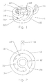
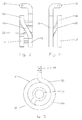
- the shorting stub 10 is formed extending outward from an inner conductor connection 12, through a connecting portion 14 that may include one or more loop segment(s) 16 before reaching an outer conductor connection 18.
- the loop segment(s) 16 may be arranged in parallel planes joined one to another by a transition segment 20.
- the loop segment(s) 16 may be formed in a wide range of configurations, or combinations of configurations such as linear, circular, arcurate, spiral, helical or the like.
- the loop segment(s) 16 may each extend from the inner conductor connection 12 to a common or multiple outer conductor connection(s) 18. Alternatively, the loop segment(s) 16 may be joined end to end.
- the inner conductor connection 12 and or the outer conductor connection 18 may be formed, for example, as loops, pins, tabs, wedges, screw ends, sockets or the like.
- one or more support(s) 22 may be included in the design that are later easily removed from the finished shorting stub.
- each of the support(s) 22, for example, parallel to a longitudinal axis of the inner conductor and with a frangible connection to each of the multiple planar loop segment(s) 16 enables easy removal of the supports without requiring an additional machining step. Placement of the supports along an inner diameter of the loop segment(s) 16 minimizes the overall size requirement of the MIM mold.
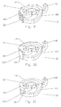
- the support(s) 22 may be formed, for example, along the outer diameter of the loop segment(s) 16, as a unitary support band 24 or as post(s) 26 positioned between the loop segment(s) 16.
- Support (22) configurations of this type may introduce cavities and overhanging portions not easily obtained by single piece molding. In these configurations separate parts may be molded to obtain "green" molded pieces that are then stacked together for the sintering step. The sintering step then joins the mating surfaces of the stacked pieces together to form a single integral component. If the support(s) 22 are formed in a configuration not easily adapted for removal by breaking a frangible joint, they may be removed with a secondary machining operation.
- One method of manufacture according to the invention includes the steps of forming a shorting stub 10 according to a desired configuration via MIM manufacturing process(s), the shorting stub 10 formed from Tungsten and or a Tungsten alloy. Any support(s) 22 included in the configuration are removed after at least the sintering steps of the MIM manufacturing process(s) have been completed.
- Adaptations to standardized MIM procedures advantageous when Tungsten and or Tungsten alloy material is being applied include selection of a compatible polymer and solvent pair for the de-binding step. Polymer rather than wax may be applied and nitric acid used as the solvent for polymer removal during de-binding. Nitric acid would react with Copper and Copper alloy material, but provides desirable de-binding results when applied to Tungsten or Tungsten alloy material.
- Tungsten and or Tungsten alloys may be applied to other RF devices with similar benefit.
- previously RF filter elements have been manufactured from specialized alloys such as INVARTM (FeNi36) a Nickel Iron alloy, known for having an extremely low thermal expansion property (2 ⁇ in/in-°C).
- INVARTM FeNi36
- Nickel Iron alloy known for having an extremely low thermal expansion property (2 ⁇ in/in-°C).
- Application of Tungsten in place of INVARTM provides an acceptable thermal expansion characteristic at a significant cost reduction.
- a shorting stub or other RF device such as a filter element may be formed according to the invention from Tungsten and or a Tungsten alloy by other manufacturing processes.
Landscapes
- Engineering & Computer Science (AREA)
- Manufacturing & Machinery (AREA)
- Powder Metallurgy (AREA)
- Injection Moulding Of Plastics Or The Like (AREA)
- Manufacturing Of Electrical Connectors (AREA)
- Waveguides (AREA)
- Details Of Aerials (AREA)
Applications Claiming Priority (2)
| Application Number | Priority Date | Filing Date | Title |
|---|---|---|---|
| US74792006P | 2006-05-22 | 2006-05-22 | |
| US11/468,708 US7583489B2 (en) | 2006-05-22 | 2006-08-30 | Tungsten shorting stub and method of manufacture |
Publications (2)
| Publication Number | Publication Date |
|---|---|
| EP1860745A2 true EP1860745A2 (de) | 2007-11-28 |
| EP1860745A3 EP1860745A3 (de) | 2012-12-05 |
Family
ID=38429951
Family Applications (1)
| Application Number | Title | Priority Date | Filing Date |
|---|---|---|---|
| EP07106799A Withdrawn EP1860745A3 (de) | 2006-05-22 | 2007-04-24 | Wolfram-Kurzschlussplatte und Herstellungsverfahren dafür |
Country Status (6)
| Country | Link |
|---|---|
| US (1) | US7583489B2 (de) |
| EP (1) | EP1860745A3 (de) |
| JP (1) | JP2007312384A (de) |
| BR (1) | BRPI0702598A (de) |
| CA (1) | CA2585101A1 (de) |
| MX (1) | MX2007004983A (de) |
Families Citing this family (1)
| Publication number | Priority date | Publication date | Assignee | Title |
|---|---|---|---|---|
| US8456789B2 (en) | 2010-12-15 | 2013-06-04 | Andrew Llc | Tunable coaxial surge arrestor |
Family Cites Families (31)
| Publication number | Priority date | Publication date | Assignee | Title |
|---|---|---|---|---|
| US3289117A (en) * | 1964-03-23 | 1966-11-29 | Sylvania Electric Prod | Surge arrestor utilizing quarter wave stubs |
| US4236188A (en) * | 1979-01-15 | 1980-11-25 | The United States Of America As Represented By The Secretary Of The Army | Coaxial terminal protection device with disposable cartridge |
| US4409637A (en) * | 1980-04-08 | 1983-10-11 | Block Roger R | Connector for electromagnetic impulse suppression |
| FR2527846A1 (fr) * | 1982-05-28 | 1983-12-02 | Labo Electronique Physique | Coupleur directionnel hyperfrequence a quatre lignes de transmission et circuit repartiteur de puissance passif realise de facon similaire |
| US4584624A (en) * | 1984-12-10 | 1986-04-22 | Northern Telecom Limited | Station protector for telecommunications systems |
| US4701825A (en) * | 1986-04-07 | 1987-10-20 | Tii Industries, Inc. | Line protector |
| US4731111A (en) * | 1987-03-16 | 1988-03-15 | Gte Products Corporation | Hydrometallurical process for producing finely divided spherical refractory metal based powders |
| US5053910A (en) * | 1989-10-16 | 1991-10-01 | Perma Power Electronics, Inc. | Surge suppressor for coaxial transmission line |
| US5314658A (en) * | 1992-04-03 | 1994-05-24 | Amax, Inc. | Conditioning metal powder for injection molding |
| JPH06260305A (ja) * | 1993-03-08 | 1994-09-16 | Fuji Electric Co Ltd | 避雷器の電流端子引出し構造 |
| AU671565B2 (en) * | 1993-10-07 | 1996-08-29 | Andrew Corporation | Surge protector connector |
| JPH09120880A (ja) * | 1995-10-26 | 1997-05-06 | Shinko Electric Ind Co Ltd | 避雷管 |
| US5745328A (en) * | 1997-03-03 | 1998-04-28 | Watkins-Johnson Company | Electromagnetic impulse suppression curcuit |
| DE19717802B4 (de) * | 1997-04-26 | 2009-09-17 | Dehn + Söhne GmbH + Co KG | Funkenstrecke |
| US6061223A (en) * | 1997-10-14 | 2000-05-09 | Polyphaser Corporation | Surge suppressor device |
| AU740311B2 (en) * | 1998-02-17 | 2001-11-01 | Huber & Suhner Ag | EMP - charge eliminator |
| JP2001094334A (ja) * | 1999-09-22 | 2001-04-06 | Mitsubishi Electric Corp | アンテナ素子、これを用いたアレイアンテナ及びアンテナ素子の製造方法 |
| JP2001148308A (ja) * | 1999-11-19 | 2001-05-29 | Toyota Motor Corp | ソレノイド |
| JP2001222935A (ja) * | 2000-02-08 | 2001-08-17 | Toshiba Corp | 真空開閉装置 |
| US6452773B1 (en) * | 2000-03-21 | 2002-09-17 | Andrew Corporation | Broadband shorted stub surge protector |
| ATE377859T1 (de) * | 2000-10-25 | 2007-11-15 | Huber+Suhner Ag | Störschutzfilter- und blitzstromableiter- einrichtung |
| US6636408B2 (en) * | 2001-03-26 | 2003-10-21 | Marconi Communications, Inc. | Coaxial transmission line surge protector assembly with an integral fuse link |
| US6790252B2 (en) * | 2001-04-18 | 2004-09-14 | Hard Metals Partnership | Tungsten-carbide articles made by metal injection molding and method |
| WO2002103875A1 (en) * | 2001-06-15 | 2002-12-27 | Kauffman George M | Protective device |
| US6721155B2 (en) * | 2001-08-23 | 2004-04-13 | Andrew Corp. | Broadband surge protector with stub DC injection |
| US6785110B2 (en) * | 2001-10-12 | 2004-08-31 | Polyphaser Corporation | Rf surge protection device |
| US6688916B1 (en) * | 2002-12-23 | 2004-02-10 | Chun Te Lee | Signal connector having function of abrupt wave protection |
| JP2005100832A (ja) * | 2003-09-25 | 2005-04-14 | Hamamatsu Photonics Kk | 放電灯用電極 |
| DE102004006954A1 (de) * | 2004-02-12 | 2005-09-01 | Basf Ag | Verfahren zum Verbinden von anorganischen, aus Pulverspritzgussmassen durch Spritzgießen hergestellten Formkörpern mit nach einem anderen Verfahren als Spritzgießen hergestellten anorganischen Formkörpern |
| US7483251B2 (en) * | 2006-01-13 | 2009-01-27 | Andrew Llc | Multiple planar inductive loop surge suppressor |
| JP2007242242A (ja) * | 2006-03-03 | 2007-09-20 | Sanyo Electric Industries Co Ltd | 避雷素子及びその製造方法 |
-
2006
- 2006-08-30 US US11/468,708 patent/US7583489B2/en active Active
-
2007
- 2007-04-17 CA CA002585101A patent/CA2585101A1/en not_active Abandoned
- 2007-04-24 EP EP07106799A patent/EP1860745A3/de not_active Withdrawn
- 2007-04-25 MX MX2007004983A patent/MX2007004983A/es active IP Right Grant
- 2007-05-09 JP JP2007125091A patent/JP2007312384A/ja active Pending
- 2007-05-21 BR BRPI0702598-0A patent/BRPI0702598A/pt not_active IP Right Cessation
Also Published As
| Publication number | Publication date |
|---|---|
| EP1860745A3 (de) | 2012-12-05 |
| MX2007004983A (es) | 2008-12-02 |
| BRPI0702598A (pt) | 2008-01-15 |
| US20070268645A1 (en) | 2007-11-22 |
| CA2585101A1 (en) | 2007-11-22 |
| JP2007312384A (ja) | 2007-11-29 |
| US7583489B2 (en) | 2009-09-01 |
Similar Documents
| Publication | Publication Date | Title |
|---|---|---|
| US20080170346A1 (en) | Folded Surface Capacitor In-line Assembly | |
| US6693601B2 (en) | Ceramic-embedded micro-electromagnetic device and method of fabrication thereof | |
| US8382534B2 (en) | System, method and apparatus for stranded canted coil spring | |
| EP4128441B1 (de) | Steckkontakt | |
| CA2631078A1 (en) | Angled coaxial connector with inner conductor transition and method of manufacture | |
| US20110003507A1 (en) | Multi-shot Connector Assembly and Method of Manufacture | |
| EP2296231A1 (de) | Multishotgegossener Koaxialstecker und Herstellungsverfahren | |
| EP2706544A1 (de) | Oberflächen-montierte Induktivität | |
| EP2475043B1 (de) | Antenne | |
| US9190707B2 (en) | Method for manufacturing an RF filter and an RF filter | |
| EP1860745A2 (de) | Wolfram-Kurzschlussplatte und Herstellungsverfahren dafür | |
| JP5479841B2 (ja) | L字型同軸コネクタ | |
| CN106098649B (zh) | 大功率贴片元件及其加工工装、制作方法 | |
| JP2007188865A (ja) | 複数平面誘導性ループ・サージ抑制装置 | |
| US10886056B2 (en) | Inductor element | |
| US12347978B2 (en) | Overmold-overmold micro radio frequency connector | |
| CN101079335A (zh) | 钨短接线及制造方法 | |
| JP6294037B2 (ja) | 複合型ノイズフィルタ | |
| JPS63124385A (ja) | 雌タ−ミナルの製造方法 | |
| CN211265727U (zh) | 一种高压大电流连接装置 | |
| BR102017005229A2 (pt) | Comutador, e, método para fabricação de um comutador. | |
| US20070259538A1 (en) | Connector for mezzanine mounting of a printed wiring board | |
| US9972443B2 (en) | Tantalum capacitor | |
| CN220856986U (zh) | 连接器、电子设备 | |
| US20180166413A1 (en) | Electrically conductive bond between at least two electrical components at a carrier mounted with electronic and/or electrical devices, said bond being formed by a bond wire |
Legal Events
| Date | Code | Title | Description |
|---|---|---|---|
| PUAI | Public reference made under article 153(3) epc to a published international application that has entered the european phase |
Free format text: ORIGINAL CODE: 0009012 |
|
| AK | Designated contracting states |
Kind code of ref document: A2 Designated state(s): AT BE BG CH CY CZ DE DK EE ES FI FR GB GR HU IE IS IT LI LT LU LV MC MT NL PL PT RO SE SI SK TR |
|
| AX | Request for extension of the european patent |
Extension state: AL BA HR MK YU |
|
| PUAL | Search report despatched |
Free format text: ORIGINAL CODE: 0009013 |
|
| AK | Designated contracting states |
Kind code of ref document: A3 Designated state(s): AT BE BG CH CY CZ DE DK EE ES FI FR GB GR HU IE IS IT LI LT LU LV MC MT NL PL PT RO SE SI SK TR |
|
| AX | Request for extension of the european patent |
Extension state: AL BA HR MK RS |
|
| RIC1 | Information provided on ipc code assigned before grant |
Ipc: H01P 1/202 20060101ALI20121029BHEP Ipc: H01R 24/48 20110101ALI20121029BHEP Ipc: H01R 13/646 20110101AFI20121029BHEP Ipc: H01P 1/28 20060101ALI20121029BHEP Ipc: H01P 11/00 20060101ALI20121029BHEP |
|
| AKY | No designation fees paid | ||
| REG | Reference to a national code |
Ref country code: DE Ref legal event code: R108 Effective date: 20130814 |
|
| STAA | Information on the status of an ep patent application or granted ep patent |
Free format text: STATUS: THE APPLICATION IS DEEMED TO BE WITHDRAWN |
|
| 18D | Application deemed to be withdrawn |
Effective date: 20130606 |