EP1860312B1 - A Method of operating a fuel injector - Google Patents
A Method of operating a fuel injector Download PDFInfo
- Publication number
- EP1860312B1 EP1860312B1 EP07252101A EP07252101A EP1860312B1 EP 1860312 B1 EP1860312 B1 EP 1860312B1 EP 07252101 A EP07252101 A EP 07252101A EP 07252101 A EP07252101 A EP 07252101A EP 1860312 B1 EP1860312 B1 EP 1860312B1
- Authority
- EP
- European Patent Office
- Prior art keywords
- injection
- fuel
- injector
- stack
- voltage
- Prior art date
- Legal status (The legal status is an assumption and is not a legal conclusion. Google has not performed a legal analysis and makes no representation as to the accuracy of the status listed.)
- Not-in-force
Links
- 239000000446 fuel Substances 0.000 title claims description 123
- 238000000034 method Methods 0.000 title claims description 48
- 238000002347 injection Methods 0.000 claims description 224
- 239000007924 injection Substances 0.000 claims description 224
- 230000008859 change Effects 0.000 claims description 48
- 238000012937 correction Methods 0.000 claims description 6
- 238000013500 data storage Methods 0.000 claims description 4
- 238000004590 computer program Methods 0.000 claims description 2
- 238000012544 monitoring process Methods 0.000 claims description 2
- 238000000926 separation method Methods 0.000 description 14
- 230000000694 effects Effects 0.000 description 13
- 238000002485 combustion reaction Methods 0.000 description 8
- 230000002123 temporal effect Effects 0.000 description 8
- 230000007423 decrease Effects 0.000 description 6
- 230000004044 response Effects 0.000 description 6
- 230000006870 function Effects 0.000 description 4
- 238000012360 testing method Methods 0.000 description 3
- 230000001276 controlling effect Effects 0.000 description 2
- 239000000463 material Substances 0.000 description 2
- 230000009467 reduction Effects 0.000 description 2
- 238000012546 transfer Methods 0.000 description 2
- 230000002411 adverse Effects 0.000 description 1
- 230000008901 benefit Effects 0.000 description 1
- 239000013078 crystal Substances 0.000 description 1
- 230000003247 decreasing effect Effects 0.000 description 1
- 230000000977 initiatory effect Effects 0.000 description 1
- 230000001105 regulatory effect Effects 0.000 description 1
- 230000008685 targeting Effects 0.000 description 1
- 230000007704 transition Effects 0.000 description 1
Images


Classifications
-
- F—MECHANICAL ENGINEERING; LIGHTING; HEATING; WEAPONS; BLASTING
- F02—COMBUSTION ENGINES; HOT-GAS OR COMBUSTION-PRODUCT ENGINE PLANTS
- F02D—CONTROLLING COMBUSTION ENGINES
- F02D41/00—Electrical control of supply of combustible mixture or its constituents
- F02D41/20—Output circuits, e.g. for controlling currents in command coils
- F02D41/2096—Output circuits, e.g. for controlling currents in command coils for controlling piezoelectric injectors
-
- F—MECHANICAL ENGINEERING; LIGHTING; HEATING; WEAPONS; BLASTING
- F02—COMBUSTION ENGINES; HOT-GAS OR COMBUSTION-PRODUCT ENGINE PLANTS
- F02D—CONTROLLING COMBUSTION ENGINES
- F02D41/00—Electrical control of supply of combustible mixture or its constituents
- F02D41/24—Electrical control of supply of combustible mixture or its constituents characterised by the use of digital means
- F02D41/2406—Electrical control of supply of combustible mixture or its constituents characterised by the use of digital means using essentially read only memories
- F02D41/2425—Particular ways of programming the data
- F02D41/2429—Methods of calibrating or learning
- F02D41/2451—Methods of calibrating or learning characterised by what is learned or calibrated
- F02D41/2464—Characteristics of actuators
- F02D41/2467—Characteristics of actuators for injectors
-
- F—MECHANICAL ENGINEERING; LIGHTING; HEATING; WEAPONS; BLASTING
- F02—COMBUSTION ENGINES; HOT-GAS OR COMBUSTION-PRODUCT ENGINE PLANTS
- F02D—CONTROLLING COMBUSTION ENGINES
- F02D41/00—Electrical control of supply of combustible mixture or its constituents
- F02D41/30—Controlling fuel injection
- F02D41/38—Controlling fuel injection of the high pressure type
- F02D41/40—Controlling fuel injection of the high pressure type with means for controlling injection timing or duration
- F02D41/402—Multiple injections
-
- F—MECHANICAL ENGINEERING; LIGHTING; HEATING; WEAPONS; BLASTING
- F02—COMBUSTION ENGINES; HOT-GAS OR COMBUSTION-PRODUCT ENGINE PLANTS
- F02D—CONTROLLING COMBUSTION ENGINES
- F02D41/00—Electrical control of supply of combustible mixture or its constituents
- F02D41/20—Output circuits, e.g. for controlling currents in command coils
- F02D2041/202—Output circuits, e.g. for controlling currents in command coils characterised by the control of the circuit
- F02D2041/2051—Output circuits, e.g. for controlling currents in command coils characterised by the control of the circuit using voltage control
-
- F—MECHANICAL ENGINEERING; LIGHTING; HEATING; WEAPONS; BLASTING
- F02—COMBUSTION ENGINES; HOT-GAS OR COMBUSTION-PRODUCT ENGINE PLANTS
- F02D—CONTROLLING COMBUSTION ENGINES
- F02D2250/00—Engine control related to specific problems or objectives
- F02D2250/04—Fuel pressure pulsation in common rails
-
- F—MECHANICAL ENGINEERING; LIGHTING; HEATING; WEAPONS; BLASTING
- F02—COMBUSTION ENGINES; HOT-GAS OR COMBUSTION-PRODUCT ENGINE PLANTS
- F02D—CONTROLLING COMBUSTION ENGINES
- F02D41/00—Electrical control of supply of combustible mixture or its constituents
- F02D41/24—Electrical control of supply of combustible mixture or its constituents characterised by the use of digital means
- F02D41/2406—Electrical control of supply of combustible mixture or its constituents characterised by the use of digital means using essentially read only memories
- F02D41/2425—Particular ways of programming the data
- F02D41/2429—Methods of calibrating or learning
- F02D41/2438—Active learning methods
-
- F—MECHANICAL ENGINEERING; LIGHTING; HEATING; WEAPONS; BLASTING
- F02—COMBUSTION ENGINES; HOT-GAS OR COMBUSTION-PRODUCT ENGINE PLANTS
- F02D—CONTROLLING COMBUSTION ENGINES
- F02D41/00—Electrical control of supply of combustible mixture or its constituents
- F02D41/24—Electrical control of supply of combustible mixture or its constituents characterised by the use of digital means
- F02D41/2406—Electrical control of supply of combustible mixture or its constituents characterised by the use of digital means using essentially read only memories
- F02D41/2425—Particular ways of programming the data
- F02D41/2429—Methods of calibrating or learning
- F02D41/2451—Methods of calibrating or learning characterised by what is learned or calibrated
- F02D41/2464—Characteristics of actuators
- F02D41/2467—Characteristics of actuators for injectors
- F02D41/247—Behaviour for small quantities
-
- F—MECHANICAL ENGINEERING; LIGHTING; HEATING; WEAPONS; BLASTING
- F02—COMBUSTION ENGINES; HOT-GAS OR COMBUSTION-PRODUCT ENGINE PLANTS
- F02D—CONTROLLING COMBUSTION ENGINES
- F02D41/00—Electrical control of supply of combustible mixture or its constituents
- F02D41/30—Controlling fuel injection
- F02D41/38—Controlling fuel injection of the high pressure type
- F02D41/40—Controlling fuel injection of the high pressure type with means for controlling injection timing or duration
- F02D41/402—Multiple injections
- F02D41/403—Multiple injections with pilot injections
-
- Y—GENERAL TAGGING OF NEW TECHNOLOGICAL DEVELOPMENTS; GENERAL TAGGING OF CROSS-SECTIONAL TECHNOLOGIES SPANNING OVER SEVERAL SECTIONS OF THE IPC; TECHNICAL SUBJECTS COVERED BY FORMER USPC CROSS-REFERENCE ART COLLECTIONS [XRACs] AND DIGESTS
- Y02—TECHNOLOGIES OR APPLICATIONS FOR MITIGATION OR ADAPTATION AGAINST CLIMATE CHANGE
- Y02T—CLIMATE CHANGE MITIGATION TECHNOLOGIES RELATED TO TRANSPORTATION
- Y02T10/00—Road transport of goods or passengers
- Y02T10/10—Internal combustion engine [ICE] based vehicles
- Y02T10/40—Engine management systems
Definitions
- the invention reiaies to a method of operating a fuei injector. More specifically, the invention relates to a method of operating a piezoelectrically actuated fuel injector in order to improve combustion efficiency.
- a piezoelectric injector typically includes a piezoelectric actuator that is operable to control an injection nozzle.
- the injection nozzle houses an injector valve needle which is movable relative to a valve needle seat under the control of the actuator.
- a hydraulic amplifier is situated between the actuator and the needle such that axial movement of the actuator causes an amplified axial movement of the needle.
- the valve needle is either caused to disengage the valve seat, in which case fuel is delivered into the associated engine cylinder through a set of outlets provided in a tip of the nozzle, or is caused to engage the valve seat, in which case fuel delivery is prevented.
- An injector drive voltage is applied to the actuator to control an injection event comprising one or more pilot injections, a main injection, and one or more post injections depending on an operating strategy which controls the volume and timing of fuel delivery in accordance with the engine demands.
- the injector drive voltage is controlled by an engine control unit.
- pilot injection may affect subsequent pilot injections
- main injection may affect a first post injection
- post injection may affect subsequent post injections. This is caused by the first injection setting up pressure variations within the nozzle.
- an injector drive voltage may comprise first and second pilot pulses and a single main injection pulse. If the magnitude and duration of the first pilot pulse are substantially equal to the magnitude and duration of the second pilot pulse, the resultant delivery rate for each pilot injection is substantially equal. Thus, the volume of fuel delivered by each pilot injection should ideally be equal.
- varying the temporal separation of the voltage pulses for the first and second pilot injections results in a variation in delivery volume, even when the same delivery volume is demanded.
- the purpose of a pilot injection is to deliver a precise amount of fuel into the combustion chamber prior to the main injection in order to initiate the combustion process gradually.
- a variation in fuel delivery volume between pilot injections is undesirable since it reduces the controllability of the combustion process. Therefore, a method of regulating the volume of fuel delivered between pilot injections is required.
- a method for controlling the volume of fuel delivered during an injection by a piezoelectrically actuated fuel injector comprising a stack of piezoelectric elements comprises driving a current through the stack for an injector opening phase to initiate the injection, and measuring a change in voltage across the stack over an injector dwell phase during which the injector is injecting.
- the method further includes adjusting an injection control parameter for at least one subsequent injection on the basis of the measured change in voltage in order to ensure a correct volume of fuel is delivered during the at least one subsequent injection.
- the method advantageously regulates the volume of fuel delivered in order to improve the controllability of the combustion process.
- the method includes adjusting the injection control parameter after a preceding injection of comparable or larger injected volume.
- an initial (preceding) injection has a comparable or larger injected fuel delivery volume compared with a subsequent injection
- the subsequent injection may be affected by the preceding injection.
- the injection control parameter By adjusting the injection control parameter to take account of the effects of the preceding injection, the accuracy of fuel volume delivery is improved.
- the method may include adjusting the injection control parameter for a second pilot injection following a first pilot injection and preceding a main injection.
- the method includes adjusting the injection control parameter for a post injection foiiowing a main injection or a preceding post injection.
- adjusting the injection control parameter includes applying a correction factor to a predetermined injection control parameter.
- the method may include determining the correction factor (e.g. using one or more look-up tables and/or data maps) on the basis of a calculated change in fuel volume delivery.
- This method may further comprise calculating the change in fuel volume delivery (e.g. using one or more look-up tables and/or data maps) on the basis of the measured change in voltage across the stack.
- the method includes determining an injector on time comprising the opening phase and the dwell phase, wherein the step of adjusting the injection control parameter includes adjusting the injector on time for the at least one subsequent injection on the basis of the measured change in voltage.
- the injection control parameter may be the dwell time.
- the injection control parameter may be the current that is driven through the stack for the injector opening phase.
- the method may further comprise selecting an operating strategy from a plurality of operating strategies on the basis of one or more engine operating conditions and performing the aforementioned steps of the invention each time a new operating strategy is selected.
- the method includes monitoring the one or more engine operating conditions, and selecting a new operating strategy from the plurality of operating strategies on the basis of changes in the one or more engine operating conditions.
- the one or more engine operating conditions may include at least one of torque, speed and fuel pressure.
- the method may include driving the injector by applying a discharge current to the stack to cause the injection of fuel, and applying a charge current to the stack in order to cease the injection of fuel.
- the method may include driving the injector by applying a charge current to the stack to cause the injection of fuel, and applying a discharge current to the stack in order to cease the injection of fuel.
- aspects of the invention relate to a computer program product comprising at least one computer program software portion which, when executed in an executing environment, is operable to implement the method of the first aspect of the invention, a data storage medium having the or each said computer software portion stored thereon, and a microcomputer provided with said data storage medium.
- a controller for a stack of a piezoelectric actuator for use in a fuel injector comprising means for driving a current through the stack for an injector opening phase, means for measuring a change in voltage across the stack over a dwell phase during which the injector is injecting, and means for adjusting an injection control parameter for at least one subsequent injection on the basis of the measured change in voltage in order to ensure a correct volume of fuel is delivered during the at least one subsequent injection.
- an injection event shall be taken to comprise one or more pilot injections, a main injection, and one or more post injections.
- An engine control unit which is associated with all of the injectors of the engine, determines an operating strategy which needs to be implemented in order to deliver the engine performance as demanded by a driver.
- An injection includes an opening phase, a dwell phase and a closing phase. The dwell phase lasts for a dwell period, t dwell , which is the time between the end of the opening phase and the start of the closing phase.
- the piezoelectric actuator controls movement of the injector valve needle in order to deliver fuel into the cylinder.
- the piezoelectric actuator is effectively a 'stack' of piezoelectric material which, when operating in an 'actuating mode', expands and contracts depending upon the voltage across it. It is known to situate the stack in a chamber of pressurised fuel (referred to as the stack chamber).
- the stack chamber itself forms a part of the supply passage between the injector inlet and the nozzle outlets.
- One injector of the type in which the stack is located within a fuel volume is described in the Applicant's granted patent number EP 0995901 .
- the injector is driven by charging the stack to different energisation levels by driving a current into or out of the stack for a given time. This results in the voltage across the stack changing and charge transfer to or from the stack. The amount of charge transferred to or from the stack determines the extent of movement of the stack, which in turn dictates the extent of lift of the injector valve needle.
- the stack When situated in a chamber of pressurised fuel, the stack, under equilibrium conditions, is referred to as being hydrostatically loaded (i.e. there is equal pressure on all sides), and in this state does not produce a change in voltage across it.
- the piezoelectric material responds to distortions in its crystal structure in order to produce a change in the voltage across the stack. For example, an increase in the voltage across the stack can be attributed to either an increase in axial pressure or a reduction in the pressure along the length of the stack.
- Figure 1 shows a torque-speed curve 1 for an engine, including fuel pressure bars 2.
- the torque-speed curve 1 is split into different areas A, B, C, D, E, and F defining various operating strategies. Each of the different strategies corresponds to a different injection event.
- strategy A may include one pilot injection, a main injection and a post injection while strategy B may include two pilot injections, a main injection and one post injection.
- the operating strategy also determines the timing of all of the injections, usually in reference to top dead centre (TDC).
- Top dead centre is a reference to the cylinder piston position associated with an injector. Combustion occurs at or around TDC once fuel is injected into the cylinder.
- Figure 1 is only an illustration and the torque-speed curve 1 may be split into far more operating strategies in practice.
- the engine control unit determines, for a required torque, speed and fuel pressure, the operating strategy, A, B, C, D, E or F, in which the engine control unit must operate to ensure the desired engine performance.
- the operating strategy determines the number and type of injections within each injection event, as well as the timing between each injection of the event.
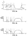
- FIG. 2a An example injection event showing an injector drive voltage that may be applied to an injector actuator is shown in Figure 2a .
- the injector drive voltage is applied by means of the engine control unit.
- the drive voltage 4 transitions from a relatively high voltage, V 0 , at which no fuel delivery occurs, to a relatively low voltage, V 1 , which initiates fuel delivery.
- An injector responsive to this drive voltage is referred to as a 'de-energise to inject' injector because, as a result of the voltage across the injector decreasing, an injection occurs.
- a corresponding ideal delivery rate profile is shown in Figure 2b .
- the injector drive voltage 4 comprises first and second pilot pulses, P1 and P2, and a single main injection pulse, P main .
- the magnitude and duration of the first pilot pulse, P1 are substantially equal to the magnitude and duration of the second pilot pulse, P2. Accordingly, the delivery rate for each pilot injection is substantially equal and, thus, the volume of fuel delivered by each pilot injection (the area under the curve) should ideally be equal, as shown in Figure 2b .
- Figure 2c shows a realistic delivery rate profile in which the fuel delivered during the second pilot injection, P2, is greater than the fuel delivered during the first pilot injection, P1, regardless of the fact that the drive pulse for the second pilot injection, P2, has the same magnitude and duration as for the first pilot injection, P1.
- the first effect is due to the movement of the valve needle from start to end of the first pilot injection, P1, initiating a pressure wave which travels through the internal fuel passages of the injector before being reflected back down to the tip of the nozzle.
- the pressure wave oscillates up and down the internal fuel passages at a particular frequency and in turn this alters the pressure along the length of the stack.
- a high pressure wave is set up such that if the needle is again caused to lift from the valve seat before the wave has dissipated there is an increase in the fuel volume delivered through the nozzle outlets.
- Fuel delivery of the second pilot injection in Figure 2c could equally have been reduced had the injector valve been caused to lift from its seat at a time when the pressure within the internal fuel passages had been low. As a result, the pressure within the internal fuel passages has a direct effect on the variation in fuel delivery, which is undesirable.
- the second effect is due to the vibrations within the nozzle and needle.
- the needle disengages and re-engages with the valve seat.
- the needle is caused to vibrate in an axial direction.
- the needle re-engages with the seat, it is still vibrating and as a result also causes the nozzle to vibrate.
- the degree to which the needle lifts during pilot injections is critical.
- the needle lift is caused to vary because of these vibrations, and as a result the volume of fuel delivery also varies.
- the needle lift will be higher than if there had been no vibration.
- the effective aperture(s) through which fuel is delivered is larger than if there had been no vibration (as in the case of the first pilot injection, P1), and a larger volume of fuel is delivered.
- the needle lift will be lower than if there had been no vibration.
- the aperture(s) through which fuel is delivered is smaller, and a smaller volume of fuel is delivered.
- the actuator When the actuator is not operating in the actuating mode, i.e. when no charge is being applied or removed from the stack, i.e. during the dwell period, the actuator effectively operates in a 'sensing mode' in which a voltage is produced by the stack in response to the variations in pressure.
- the stack is sensitive to variations in axial pressure and also variations in pressure along the length of the stack.
- the pressure waves within the internal fuel passages when there is a high pressure wave at the tip of the nozzle there is a low pressure wave at the stack. This is equivalent to a reduction in pressure along the length of the stack which, as described above, causes an increase in the voltage across the stack.
- low pressure at the tip of the nozzle results in an increase in pressure along the length of the stack and a decrease in the voltage across the stack in comparison to an expected nominal voltage increase, ⁇ V nominal , which is described in more detail later.
- Figure 3 shows the effect of varying the temporal separation of the voltage pulses for the first and second pilot injections, P1 and P2.
- varying the time between the pilot injections has no effect on the fuel delivery volume of the first pilot injection, P1, since no pressure wave has been set up as a result of a previous injection pulse (the fuel pressure can be considered as being in a steady state condition), and the needle is not vibrating as a result of previous injections.
- the fuel delivery volume for the second pilot injection, P2 which corresponds to the pressure wave oscillating back and forth through the fuel passages, and the vibrations within the needle and nozzle causing variations in needle lift.
- Figure 3 shows the peak-to-peak variation in fuel delivery volume, ⁇ FDVpk-pk.
- Figure 4 is a graph of change in actuator voltage, ⁇ V, during the dwell period, t dwell , versus the temporal separation between the pilot injections, P1 and P2.
- the actuator voltage measured during the dwell period, t dwell varies as the separation between the pilot injections is increased.
- the relationship between the change in actuator voltage, ⁇ V, and the injection separation is substantially sinusoidal and, by comparing Figure 4 with Figure 3 , it can be seen that both waveforms have substantially the same frequency and phase.
- Reference numeral 7 in particular shows that the peaks and troughs of Figures 3 and 4 coincide.
- the present invention is borne from the inventor's realisation that a change in voltage across the stack, which is not in response to the drive voltage, is indicative of a variation in fuel pressure along the length of the stack and/or a variation in axial pressure on the stack. These variations either separately or in combination cause an unwanted variation in fuel delivery.
- the perceived change in voltage can be used to adjust the drive voltage of the second pilot injection P2 in order to remove or alleviate the variation in fuel delivery.
- Figure 5a shows a voltage profile for the first and second pilot injections, P1 and P2.
- the actuator voltage decreases from a high voltage level, V 0 , to a low voltage level, V 1 , during the discharge/opening phase.
- the voltage increases slightly from V 1 to V 2_nominal .
- the discharge/opening phase and the dwell period, t dwell together correspond to an injector on time, TON, as shown in Figure 5b .
- the injector on time, TON is a control parameter for the injector, which is determined by the engine control unit (ECU), and is a function of fuel pressure.
- the injector on time, TON is controlled by the ECU in order to ensure that the correct volume of fuel is delivered.
- the voltage subsequently increases back to V 0 during a charging/closing phase prior to the second pilot injection, P2, in which the voltage decreases again to V 1 .
- the voltage across the stack increases to a voltage between V 2_low and V 2_high . If the voltage increases to V 2_nominal , the fuel delivery volume during the second pilot injection, P2, will equal the fuel volume during the first pilot injection, P1(i.e. the desired volume of fuel will be delivered). This corresponds, as shown in Figure 3 , to where the waveform for the second pilot injection, P2, crosses the waveform for the first pilot injection, P1, at reference 6 (i.e. where delivered fuel volumes are equal).
- a nominal voltage increase, ⁇ V nominal, is typical for both the first and second pilot injections, P1 and P2. This is the voltage increase which results in the desired volume of fuel being delivered, again corresponding to where the waveform for the first pilot injection, P1, intersects the waveform for the second-pilot injection, P2, in Figure 3 .
- a voltage increase smaller than the nominal voltage increase, ⁇ V nominal is indicative of low pressure at the tip of the nozzle and/or low needle lift causing a decrease in the fuel delivery volume, as shown by the long dashed line 8 in Figure 5c
- a voltage increase larger than the nominal voltage increase ⁇ V nominal is indicative of high pressure at the tip of the nozzle and/or high needle lift causing an increase in the fuel delivery volume, as shown by the short dashed line 10 in Figure 5c .
- the invention provides a method for compensating for such a variation between the desired volume of fuel to be delivered and the actual volume of fuel delivered by compensating for the effects of the pressure waves and needle lift variations that are setup as a result of an earlier injection.
- the relationship between the change in voltage, ⁇ V, and the pilot injection separation shown in Figure 3 has the same frequency and phase as the change in fuel volume delivery, ⁇ del, shown in Figure 4 . Therefore, it can be said that the change in fuel volume delivery, ⁇ deI, varies as a function of the change in voltage, ⁇ V.
- the function itself is not important to the control method since during testing of the injector, data is mapped into look-up tables or data maps and this data is then accessed real-time to apply the appropriate correction.
- Figure 6 shows this relationship graphically for a particular fuel pressure, in this case 1000 bar. This graph will vary for different fuel pressures, injector on times TONs, and stack temperatures.
- ⁇ and ⁇ are deduced and stored in look-up tables or data maps for a range of fuel pressures and stack temperatures.
- the change in fuel volume delivery, ⁇ del, resulting from a change in voltage, ⁇ V can be derived from the look-up tables or data maps, in accordance with the above equation, depending on rail pressure and stack temperature.
- values for the change in fuel volume delivery, ⁇ deI can be stored directly in look-up tables or data maps for a range of changes in voltage, ⁇ V, measured during testing.
- Figure 7 shows the relationship between the volume of fuel delivered and the injector on time, TON, at different fuel pressures. Data corresponding to these graphs is also stored in look-up tables or data maps.
- the change in fuel volume delivery, ⁇ deI, determined above is used to determine a required change in the injector on time, TON, (i.e. the injector on time calculated to deliver the desired volume of fuel is adjusted by ⁇ TON to ensure consistent fuel delivery).
- TON there is a delay of one injection event before the corrected injector on time, can be implemented to correct the fuel volume delivery error.
- the error in fuel delivery has to occur once in order for the change in voltage, ⁇ V, during the second pilot injection, P2, to occur.
- This change in voltage, ⁇ V is then used to calculate the required change in injector on time, ⁇ TON, which is then applied to all subsequent injection events of this nature operating with the same operating strategy (i.e. the adjustment to the injector on time that is calculated for a second pilot injection is applied to the second pilot injection in a subsequent injection event sequence).
- the error associated with one occurrence of an injection event with an erroneous fuel delivery is negligible.
- the present invention advantageously ensures that the volume of fuel delivered is consistent. Furthermore, combustion efficiency is improved due to the greater degree of control that is provided over the volume of fuel delivered.
- the engine control unit selects an operating strategy depending on fuel pressure, engine demand, and engine temperature. This is achieved using look up tables or data maps that are populated with information derived from a graph like that shown in Figure 1 .
- an initial injection event sequence injector drive waveform
- injector drive waveform is determined, including determining (i) the number and timing of injections within the injection event, and (ii) a predetermined injector on time, TON_det, for each injection within the injection event.
- the injection event includes one, two or more pilot injections, a main injection and one, two or more post injections.
- step 102 for each injection within the selected injection event, the engine control unit drives the injector for the opening phase of the predetermined injector on time, TON_det.
- step 103 the engine control unit monitors the change in voltage, ⁇ V, that occurs during the dwell periods, t dwell , of the second and subsequent pilot injections (if any) and all of the post injections (if any), and records these values in its memory.
- step 104 the operating strategy is again determined and the next injection event sequence is initiated. Assuming a steady state condition (i.e. the operating strategy has not changed), the next injection event sequence will be equivalent to the initial injection event sequence of step 101.
- the engine control unit uses the measured values for ⁇ V, as recorded in step 103, to determine a required change in injector on time, ⁇ TON, for each of the second and subsequent pilot injections and all of the post injections of the next injection sequence, by reference to predetermined look-up tables or data maps.
- the predetermined injector on times, TON_det are adjusted on the basis of the required change in injector on time, ⁇ TON (i.e. as determined in step 105).
- TON_adj each comprising an opening phase and a dwell phase
- this step applies a correction factor to the injector on time, so that when the corrected injector on time is applied to the next injection event sequence the required volume of fuel delivery is achieved.
- the discharge current level remains unchanged and the dwell time remains unchanged.
- the opening phase is adjusted, however, so that the amount of charge transferred from the stack is adjusted.
- the amount of charge transferred from the stack will increase so that the actuator stack is extended further and, hence, the injector valve needle is lifted higher.
- the injector is driven for the opening phases of the injector on times using the predetermined injector in times, TON_det (as determined in step 101) for the first pilot injection, P1, and the main injection (i.e. these injector on times are not corrected).
- TON_det as determined in step 101
- the injector is driven for the opening phases of the adjusted injector on times, TON_adj, as determined in step 105.
- Steps 104, 105, 106 and 107 continue for as long as the injection event sequence remains the same (i.e. the operating strategy remains in a steady state condition), so that the adjusted injector on times continue to be applied to the second and subsequent pilot injections and all of the post injections.
- steps 104, 105, 106 and 107 will be repeated for as long as the injection event sequence remains unchanged (i.e. the new operating strategy remains the same).
- the invention provides a closed loop system that compensates for possible errors in fuel delivery that occur between adjacent injection event sequences. It will be appreciated that
- the engine control unit only monitors those injections that follow a preceding injection have a comparable or larger injected fuel volume as it is only those injections for which the aforementioned pressure wave effects and needle lift variations are significant.
- all injections of the initial injection event sequence may be monitored in step 103, even if they return a nil value for ⁇ V.
- an adjusted injector on time TON_adj may therefore be determined, even if the data map has returned a nil value for ⁇ TON.
- the injector is driven by driving a selected current into or out of the piezoelectric stack for a predetermined period of time, in order to transfer a demanded amount of charge to/from the piezoelectric actuator.
- This has the effect of varying the voltage across the stack and is referred to as a "charge control" method.
- the invention is equally applicable to a method in which the injector is driven by controlling directly the voltage across the piezoelectric stack, targeting a demanded voltage and measuring the voltage across the piezoelectric stack in a "voltage control" method.
- an alternative injection control parameter may be adjusted in response to the measured change in voltage, ⁇ V, in order to ensure a consistent fuel delivery volume.
- the injector on time, TON instead of adjusting the injector on time, TON, the level of current that is driven through the injector may be adjusted, depending on the measured change in voltage, ⁇ V. As the injector on time TON remains unchanged, the opening phase and the dwell time remain unchanged and, as the current level is adjusted, the amount of charge transferred from the stack during the discharge phase of a second (and subsequent) injection will also be adjusted.
- the dwell time of the injection event is adjusted for a second (and subsequent) injection in response to the measured change in voltage, ⁇ V, but the injector on time, TON, and the discharge current level remain unchanged.
- the amount of charge that is transferred from the stack for the second (and subsequent) injection remains the unchanged so the extent of movement of the actuator remains unchanged and, hence, the lift of the valve needle remains unchanged.
Description
- The invention reiaies to a method of operating a fuei injector. More specifically, the invention relates to a method of operating a piezoelectrically actuated fuel injector in order to improve combustion efficiency.
- In an internal combustion engine, it is known to deliver fuel into cylinders of the engine by means of a fuel injector associated with each cylinder. One such type of fuel injector that permits precise metering of fuel is a so-called 'piezoelectric injector'.
- Typically, a piezoelectric injector includes a piezoelectric actuator that is operable to control an injection nozzle. The injection nozzle houses an injector valve needle which is movable relative to a valve needle seat under the control of the actuator. A hydraulic amplifier is situated between the actuator and the needle such that axial movement of the actuator causes an amplified axial movement of the needle. Depending on the voltage applied to the piezoelectric actuator, the valve needle is either caused to disengage the valve seat, in which case fuel is delivered into the associated engine cylinder through a set of outlets provided in a tip of the nozzle, or is caused to engage the valve seat, in which case fuel delivery is prevented.
- An injector drive voltage is applied to the actuator to control an injection event comprising one or more pilot injections, a main injection, and one or more post injections depending on an operating strategy which controls the volume and timing of fuel delivery in accordance with the engine demands. The injector drive voltage is controlled by an engine control unit.
- It has been observed that, using current engine control methods, some injections may adversely effect subsequent injections of a comparable or smaller size. A pilot injection may affect subsequent pilot injections, a main injection may affect a first post injection, or a post injection may affect subsequent post injections. This is caused by the first injection setting up pressure variations within the nozzle.
- For example, an injector drive voltage may comprise first and second pilot pulses and a single main injection pulse. If the magnitude and duration of the first pilot pulse are substantially equal to the magnitude and duration of the second pilot pulse, the resultant delivery rate for each pilot injection is substantially equal. Thus, the volume of fuel delivered by each pilot injection should ideally be equal.
- However, it has now been observed that varying the temporal separation of the voltage pulses for the first and second pilot injections results in a variation in delivery volume, even when the same delivery volume is demanded. The purpose of a pilot injection is to deliver a precise amount of fuel into the combustion chamber prior to the main injection in order to initiate the combustion process gradually. A variation in fuel delivery volume between pilot injections is undesirable since it reduces the controllability of the combustion process. Therefore, a method of regulating the volume of fuel delivered between pilot injections is required.
- For further information regarding a known injection valve and control method, the reader is directed to
DE-A-10024662 . - According to a first aspect of the invention, a method for controlling the volume of fuel delivered during an injection by a piezoelectrically actuated fuel injector comprising a stack of piezoelectric elements, comprises driving a current through the stack for an injector opening phase to initiate the injection, and measuring a change in voltage across the stack over an injector dwell phase during which the injector is injecting. The method further includes adjusting an injection control parameter for at least one subsequent injection on the basis of the measured change in voltage in order to ensure a correct volume of fuel is delivered during the at least one subsequent injection.
- The method advantageously regulates the volume of fuel delivered in order to improve the controllability of the combustion process.
- In a preferred embodiment, the method includes adjusting the injection control parameter after a preceding injection of comparable or larger injected volume.
- If an initial (preceding) injection has a comparable or larger injected fuel delivery volume compared with a subsequent injection, the subsequent injection may be affected by the preceding injection. By adjusting the injection control parameter to take account of the effects of the preceding injection, the accuracy of fuel volume delivery is improved.
- By way of example, the method may include adjusting the injection control parameter for a second pilot injection following a first pilot injection and preceding a main injection. In another example, the method includes adjusting the injection control parameter for a post injection foiiowing a main injection or a preceding post injection.
- Preferably, adjusting the injection control parameter includes applying a correction factor to a predetermined injection control parameter.
- In one embodiment, for example, the method may include determining the correction factor (e.g. using one or more look-up tables and/or data maps) on the basis of a calculated change in fuel volume delivery. This method may further comprise calculating the change in fuel volume delivery (e.g. using one or more look-up tables and/or data maps) on the basis of the measured change in voltage across the stack.
- In one embodiment, the method includes determining an injector on time comprising the opening phase and the dwell phase, wherein the step of adjusting the injection control parameter includes adjusting the injector on time for the at least one subsequent injection on the basis of the measured change in voltage.
- In another embodiment, the injection control parameter may be the dwell time.
- In a still further embodiment, the injection control parameter may be the current that is driven through the stack for the injector opening phase.
- The method may further comprise selecting an operating strategy from a plurality of operating strategies on the basis of one or more engine operating conditions and performing the aforementioned steps of the invention each time a new operating strategy is selected.
- Preferably, the method includes monitoring the one or more engine operating conditions, and selecting a new operating strategy from the plurality of operating strategies on the basis of changes in the one or more engine operating conditions.
- For example, the one or more engine operating conditions may include at least one of torque, speed and fuel pressure.
- The method may include driving the injector by applying a discharge current to the stack to cause the injection of fuel, and applying a charge current to the stack in order to cease the injection of fuel. Alternatively, the method may include driving the injector by applying a charge current to the stack to cause the injection of fuel, and applying a discharge current to the stack in order to cease the injection of fuel.
- Other aspects of the invention relate to a computer program product comprising at least one computer program software portion which, when executed in an executing environment, is operable to implement the method of the first aspect of the invention, a data storage medium having the or each said computer software portion stored thereon, and a microcomputer provided with said data storage medium.
- According to a still further aspect of the invention, there is provided a controller for a stack of a piezoelectric actuator for use in a fuel injector, comprising means for driving a current through the stack for an injector opening phase, means for measuring a change in voltage across the stack over a dwell phase during which the injector is injecting, and means for adjusting an injection control parameter for at least one subsequent injection on the basis of the measured change in voltage in order to ensure a correct volume of fuel is delivered during the at least one subsequent injection.
- It will be appreciated that any of the steps of the method of the first aspect of the invention may be implemented within a controller of the further aspect of the invention, alone or in appropriate combination.
- Preferred embodiments of the invention will now be described, by way of example only, with reference to the accompanying drawings in which:
-
- Figure 1
- shows a torque-speed curve for an engine and illustrates a number of pressure bars,
- Figure 2a
- shows an injector drive voltage signal for an injection event comprising voltage pulses for a first pilot injection, a second pilot injection and a main injection,
- Figure 2b
- shows the ideal fuel delivery volume waveform resulting from the drive voltage signal of
Figure 2a , - Figure 2c
- shows an example of a fuel volume delivery waveform, which may result in response to the drive voltage signal of
Figure 2a , - Figure 3
- shows the variation in fuel delivery volume as a function of the temporal separation of the voltage pulses for the first and second pilot injections,
- Figure 4
- is a graph of the change in actuator voltage against pilot pulse separation for a dwell phase (dwell period) between the end of an opening phase and the start of a closing phase,
- Figure 5a
- is a voltage discharge profile of the first and second pilot injections separated by a first predetermined time interval,
- Figure 5b
- shows the "injector on time" TON associated with the voltage discharge profile of
Figure 5a , - Figure 5c
- shows a fuel volume delivery waveform associated with the voltage discharge profile of
Figure 5a , - Figure 6
- shows the linear relationship between change in fuel volume delivered and change in voltage over the dwell period,
- Figure 7
- shows graphs for fuel volume delivered versus an "injector on time" TON for a number of different fuel pressures, and
- Figure 8
- is a flow chart illustrating a control method according to an embodiment of the invention.
- For the purpose of the following description, an injection event shall be taken to comprise one or more pilot injections, a main injection, and one or more post injections. An engine control unit, which is associated with all of the injectors of the engine, determines an operating strategy which needs to be implemented in order to deliver the engine performance as demanded by a driver. An injection includes an opening phase, a dwell phase and a closing phase. The dwell phase lasts for a dwell period, tdwell, which is the time between the end of the opening phase and the start of the closing phase.
- During an injection, the piezoelectric actuator controls movement of the injector valve needle in order to deliver fuel into the cylinder. The piezoelectric actuator is effectively a 'stack' of piezoelectric material which, when operating in an 'actuating mode', expands and contracts depending upon the voltage across it. It is known to situate the stack in a chamber of pressurised fuel (referred to as the stack chamber). The stack chamber itself forms a part of the supply passage between the injector inlet and the nozzle outlets. One injector of the type in which the stack is located within a fuel volume is described in the Applicant's
granted patent number EP 0995901 . - The injector is driven by charging the stack to different energisation levels by driving a current into or out of the stack for a given time. This results in the voltage across the stack changing and charge transfer to or from the stack. The amount of charge transferred to or from the stack determines the extent of movement of the stack, which in turn dictates the extent of lift of the injector valve needle.
- When situated in a chamber of pressurised fuel, the stack, under equilibrium conditions, is referred to as being hydrostatically loaded (i.e. there is equal pressure on all sides), and in this state does not produce a change in voltage across it. The piezoelectric material responds to distortions in its crystal structure in order to produce a change in the voltage across the stack. For example, an increase in the voltage across the stack can be attributed to either an increase in axial pressure or a reduction in the pressure along the length of the stack.
-
Figure 1 shows a torque-speed curve 1 for an engine, including fuel pressure bars 2. The torque-speed curve 1 is split into different areas A, B, C, D, E, and F defining various operating strategies. Each of the different strategies corresponds to a different injection event. For example, strategy A may include one pilot injection, a main injection and a post injection while strategy B may include two pilot injections, a main injection and one post injection. The operating strategy also determines the timing of all of the injections, usually in reference to top dead centre (TDC). Top dead centre is a reference to the cylinder piston position associated with an injector. Combustion occurs at or around TDC once fuel is injected into the cylinder.Figure 1 is only an illustration and the torque-speed curve 1 may be split into far more operating strategies in practice. - The engine control unit determines, for a required torque, speed and fuel pressure, the operating strategy, A, B, C, D, E or F, in which the engine control unit must operate to ensure the desired engine performance. The operating strategy determines the number and type of injections within each injection event, as well as the timing between each injection of the event.
- Changes between operating in one operating strategy (i.e. an injection event sequence having a specific injector drive waveform) and another typically occur over a long period of time in comparison to the length of the injection event sequences themselves. As a result, an injection event sequence associated with one operating strategy will occur many times before conditions change and a different injection event sequence is required.
- An example injection event showing an injector drive voltage that may be applied to an injector actuator is shown in
Figure 2a . The injector drive voltage is applied by means of the engine control unit. The drive voltage 4 transitions from a relatively high voltage, V0, at which no fuel delivery occurs, to a relatively low voltage, V1, which initiates fuel delivery. An injector responsive to this drive voltage is referred to as a 'de-energise to inject' injector because, as a result of the voltage across the injector decreasing, an injection occurs. A corresponding ideal delivery rate profile is shown inFigure 2b . - In
Figure 2a , the injector drive voltage 4 comprises first and second pilot pulses, P1 and P2, and a single main injection pulse, Pmain. The magnitude and duration of the first pilot pulse, P1, are substantially equal to the magnitude and duration of the second pilot pulse, P2. Accordingly, the delivery rate for each pilot injection is substantially equal and, thus, the volume of fuel delivered by each pilot injection (the area under the curve) should ideally be equal, as shown inFigure 2b . -
Figure 2c shows a realistic delivery rate profile in which the fuel delivered during the second pilot injection, P2, is greater than the fuel delivered during the first pilot injection, P1, regardless of the fact that the drive pulse for the second pilot injection, P2, has the same magnitude and duration as for the first pilot injection, P1. - There are two effects within the injector which, either separately or in combination, can be attributed to variations in the volume of fuel delivered during second and subsequent injections of an injection event sequence.
- The first effect is due to the movement of the valve needle from start to end of the first pilot injection, P1, initiating a pressure wave which travels through the internal fuel passages of the injector before being reflected back down to the tip of the nozzle. The pressure wave oscillates up and down the internal fuel passages at a particular frequency and in turn this alters the pressure along the length of the stack. When the pressure wave travels towards the tip of the nozzle, a high pressure wave is set up such that if the needle is again caused to lift from the valve seat before the wave has dissipated there is an increase in the fuel volume delivered through the nozzle outlets. Conversely, when the pressure wave travels away from the tip of the nozzle, a low pressure wave is set up, such that if the needle is again caused to lift from the valve seat before the wave has dissipated there is a decrease in the fuel volume delivered through the nozzle outlets. As a result, the actual fuel volume delivered between pilot injections for the same drive voltage varies considerably, depending upon the temporal separation of the pilot injections.
- Fuel delivery of the second pilot injection in
Figure 2c could equally have been reduced had the injector valve been caused to lift from its seat at a time when the pressure within the internal fuel passages had been low. As a result, the pressure within the internal fuel passages has a direct effect on the variation in fuel delivery, which is undesirable. - The second effect is due to the vibrations within the nozzle and needle. During the first pilot injection the needle disengages and re-engages with the valve seat. When the needle disengages from the valve seat, the needle is caused to vibrate in an axial direction. When the needle re-engages with the seat, it is still vibrating and as a result also causes the nozzle to vibrate. The degree to which the needle lifts during pilot injections (or any injection where only a relatively small volume of fuel is to be delivered) is critical. Depending upon the temporal separation of the first and second pilot injections, P1 and P2, the needle lift is caused to vary because of these vibrations, and as a result the volume of fuel delivery also varies.
- For example, if, for the second pilot injection, the needle is caused to disengage from the valve seat while the vibration is causing the needle to move in a direction away from the seat, then during the second pilot injection, P2, the needle lift will be higher than if there had been no vibration. As a result, the effective aperture(s) through which fuel is delivered is larger than if there had been no vibration (as in the case of the first pilot injection, P1), and a larger volume of fuel is delivered. Conversely if, for the second pilot injection, the needle is caused to disengage from the valve seat while the vibration is causing the needle to move in a direction towards the seat, then, during the second pilot injection, P2, the needle lift will be lower than if there had been no vibration. As a result, the aperture(s) through which fuel is delivered is smaller, and a smaller volume of fuel is delivered. The vibrations within the needle and nozzle also have a direct effect on the variation in fuel delivery and this is undesirable.
- As described above, variations in the temporal separation of the pilot injections cause variations in the volume of fuei delivered during the second pilot injection, P2, and this can be attributed to either or both of the aforedescribed pressure waves or needle lift variations. However, the piezoelectric stack, being immersed in high pressure fuel within the stack chamber, is also affected by the pressure waves and needle lift variations.
- When the actuator is not operating in the actuating mode, i.e. when no charge is being applied or removed from the stack, i.e. during the dwell period, the actuator effectively operates in a 'sensing mode' in which a voltage is produced by the stack in response to the variations in pressure. As described above, the stack is sensitive to variations in axial pressure and also variations in pressure along the length of the stack. With regard to the pressure waves within the internal fuel passages, when there is a high pressure wave at the tip of the nozzle there is a low pressure wave at the stack. This is equivalent to a reduction in pressure along the length of the stack which, as described above, causes an increase in the voltage across the stack. Conversely, low pressure at the tip of the nozzle results in an increase in pressure along the length of the stack and a decrease in the voltage across the stack in comparison to an expected nominal voltage increase, ΔVnominal, which is described in more detail later.
- Similarly, with regard to the needle lift variations caused by the vibrations, when the needle lift is higher than it would be if there were no vibrations, the needle exerts increased axial pressure on the stack (by way of the hydraulic amplifier). As described above, an increase in axial pressure results in an increase in the voltage across the stack. Conversely, low axial pressure results in a decrease in the voltage across the stack in comparison to the expected nominal voltage increase, ΔVnominal.
-
Figure 3 shows the effect of varying the temporal separation of the voltage pulses for the first and second pilot injections, P1 and P2. As shown, varying the time between the pilot injections has no effect on the fuel delivery volume of the first pilot injection, P1, since no pressure wave has been set up as a result of a previous injection pulse (the fuel pressure can be considered as being in a steady state condition), and the needle is not vibrating as a result of previous injections. However, there is a cyclical variation in the fuel delivery volume for the second pilot injection, P2, which corresponds to the pressure wave oscillating back and forth through the fuel passages, and the vibrations within the needle and nozzle causing variations in needle lift.Figure 3 shows the peak-to-peak variation in fuel delivery volume, ΔFDVpk-pk. - The perceived effect of the pressure waves and needle lift variations as a result of varying the temporal separation between pilot injections, P1 and P2, is shown in
Figure 4 , which is a graph of change in actuator voltage, ΔV, during the dwell period, tdwell, versus the temporal separation between the pilot injections, P1 and P2. As shown, the actuator voltage measured during the dwell period, tdwell, varies as the separation between the pilot injections is increased. The relationship between the change in actuator voltage, ΔV, and the injection separation is substantially sinusoidal and, by comparingFigure 4 withFigure 3 , it can be seen that both waveforms have substantially the same frequency and phase. Reference numeral 7 in particular shows that the peaks and troughs ofFigures 3 and 4 coincide.
Without being bound by theory, the present invention is borne from the inventor's realisation that a change in voltage across the stack, which is not in response to the drive voltage, is indicative of a variation in fuel pressure along the length of the stack and/or a variation in axial pressure on the stack. These variations either separately or in combination cause an unwanted variation in fuel delivery. The perceived change in voltage can be used to adjust the drive voltage of the second pilot injection P2 in order to remove or alleviate the variation in fuel delivery. -
Figure 5a shows a voltage profile for the first and second pilot injections, P1 and P2. As shown, for the first pilot injection, P1, the actuator voltage decreases from a high voltage level, V0, to a low voltage level, V1, during the discharge/opening phase. During the dwell period, tdwell, of the first pilot injection, P1, the voltage increases slightly from V1 to V2_nominal. - The discharge/opening phase and the dwell period, tdwell, together correspond to an injector on time, TON, as shown in
Figure 5b . The injector on time, TON, is a control parameter for the injector, which is determined by the engine control unit (ECU), and is a function of fuel pressure. The injector on time, TON, is controlled by the ECU in order to ensure that the correct volume of fuel is delivered. - After the dwell period tdwell, the voltage subsequently increases back to V0 during a charging/closing phase prior to the second pilot injection, P2, in which the voltage decreases again to V1. During the dwell phase of the second pilot injection the voltage across the stack increases to a voltage between V2_low and V2_high. If the voltage increases to V2_nominal, the fuel delivery volume during the second pilot injection, P2, will equal the fuel volume during the first pilot injection, P1(i.e. the desired volume of fuel will be delivered). This corresponds, as shown in
Figure 3 , to where the waveform for the second pilot injection, P2, crosses the waveform for the first pilot injection, P1, at reference 6 (i.e. where delivered fuel volumes are equal). In other words, when the separation between pilot injections is chosen to be of one particular duration, it happens that the volume of fuel delivered during the second pilot injection, P2, equals the volume delivered during the first pilot injection, P1 (i.e. the desired fuel volume is delivered). However, at other separation durations the volume of fuel delivered during the second pilot injection, P2, can be significantly different from the desired amount. - A nominal voltage increase, ΔVnominal, is typical for both the first and second pilot injections, P1 and P2. This is the voltage increase which results in the desired volume of fuel being delivered, again corresponding to where the waveform for the first pilot injection, P1, intersects the waveform for the second-pilot injection, P2, in
Figure 3 . - However, during the dwell period, tdwell, of the second pilot injection, P2, the pressure variations described above cause a voltage change either greater or smaller than the nominal voltage, V2-nominal. A voltage increase smaller than the nominal voltage increase, ΔVnominal (i.e. between V2_low and V2_nominal) is indicative of low pressure at the tip of the nozzle and/or low needle lift causing a decrease in the fuel delivery volume, as shown by the long dashed line 8 in
Figure 5c , and a voltage increase larger than the nominal voltage increase ΔVnominal (i.e. between V2_nominal and V2_high) is indicative of high pressure at the tip of the nozzle and/or high needle lift causing an increase in the fuel delivery volume, as shown by the short dashedline 10 inFigure 5c . - The invention provides a method for compensating for such a variation between the desired volume of fuel to be delivered and the actual volume of fuel delivered by compensating for the effects of the pressure waves and needle lift variations that are setup as a result of an earlier injection.
- As described above, the relationship between the change in voltage, ΔV, and the pilot injection separation shown in
Figure 3 has the same frequency and phase as the change in fuel volume delivery, Δdel, shown inFigure 4 . Therefore, it can be said that the change in fuel volume delivery, ΔdeI, varies as a function of the change in voltage, ΔV. The function itself is not important to the control method since during testing of the injector, data is mapped into look-up tables or data maps and this data is then accessed real-time to apply the appropriate correction. - As an example, supposing that the relationship between the change in voltage, ΔV, and the resultant change in fuel volume delivery, Δdel, is considered to be substantially linear then the relationship would be given by the equation:

where φ and ψ are constants -
Figure 6 shows this relationship graphically for a particular fuel pressure, in thiscase 1000 bar. This graph will vary for different fuel pressures, injector on times TONs, and stack temperatures. During testing values for φ and ψ are deduced and stored in look-up tables or data maps for a range of fuel pressures and stack temperatures. As a result, the change in fuel volume delivery, Δdel, resulting from a change in voltage, ΔV, can be derived from the look-up tables or data maps, in accordance with the above equation, depending on rail pressure and stack temperature. - Alternatively, values for the change in fuel volume delivery, ΔdeI, can be stored directly in look-up tables or data maps for a range of changes in voltage, ΔV, measured during testing.
-
Figure 7 shows the relationship between the volume of fuel delivered and the injector on time, TON, at different fuel pressures. Data corresponding to these graphs is also stored in look-up tables or data maps. The change in fuel volume delivery, ΔdeI, determined above is used to determine a required change in the injector on time, TON, (i.e. the injector on time calculated to deliver the desired volume of fuel is adjusted by ΔTON to ensure consistent fuel delivery). - It is worth noting that there is a delay of one injection event before the corrected injector on time, TON, can be implemented to correct the fuel volume delivery error. In other words, the error in fuel delivery has to occur once in order for the change in voltage, ΔV, during the second pilot injection, P2, to occur. This change in voltage, ΔV, is then used to calculate the required change in injector on time, ΔTON, which is then applied to all subsequent injection events of this nature operating with the same operating strategy (i.e. the adjustment to the injector on time that is calculated for a second pilot injection is applied to the second pilot injection in a subsequent injection event sequence). As changes in operating strategy occur over a much longer time scale than the injection events themseives, the error associated with one occurrence of an injection event with an erroneous fuel delivery is negligible.
- The present invention advantageously ensures that the volume of fuel delivered is consistent. Furthermore, combustion efficiency is improved due to the greater degree of control that is provided over the volume of fuel delivered.
- It is to be appreciated that although the above description relates to an operating strategy which has two pilot injections, the invention need not be limited to pilot injections as will be understood from the example below.
- The method of the invention is further described with reference to the flow chart of
Figure 8 . - As shown, at
step 101 the engine control unit selects an operating strategy depending on fuel pressure, engine demand, and engine temperature. This is achieved using look up tables or data maps that are populated with information derived from a graph like that shown inFigure 1 . Depending on the selected operating strategy, an initial injection event sequence (injector drive waveform) is determined, including determining (i) the number and timing of injections within the injection event, and (ii) a predetermined injector on time, TON_det, for each injection within the injection event. Typically the injection event includes one, two or more pilot injections, a main injection and one, two or more post injections. - In
step 102, for each injection within the selected injection event, the engine control unit drives the injector for the opening phase of the predetermined injector on time, TON_det. - In
step 103, the engine control unit monitors the change in voltage, ΔV, that occurs during the dwell periods, tdwell, of the second and subsequent pilot injections (if any) and all of the post injections (if any), and records these values in its memory. - Once the initial injection event sequence has completed, at
step 104 the operating strategy is again determined and the next injection event sequence is initiated. Assuming a steady state condition (i.e. the operating strategy has not changed), the next injection event sequence will be equivalent to the initial injection event sequence ofstep 101. - At
step 105, the engine control unit uses the measured values for ΔV, as recorded instep 103, to determine a required change in injector on time, ΔTON, for each of the second and subsequent pilot injections and all of the post injections of the next injection sequence, by reference to predetermined look-up tables or data maps. - At
step 106, the predetermined injector on times, TON_det (i.e. as determined in step 101) are adjusted on the basis of the required change in injector on time, ΔTON (i.e. as determined in step 105). This gives an adjusted injector on time, TON_adj (each comprising an opening phase and a dwell phase) for each of the second and subsequent pilot injections and all of the post injections, as necessary. Essentially, this step applies a correction factor to the injector on time, so that when the corrected injector on time is applied to the next injection event sequence the required volume of fuel delivery is achieved. - Despite correcting the injector on time, the discharge current level remains unchanged and the dwell time remains unchanged. The opening phase is adjusted, however, so that the amount of charge transferred from the stack is adjusted. For an increase in the injector on time, the amount of charge transferred from the stack will increase so that the actuator stack is extended further and, hence, the injector valve needle is lifted higher.
- At
step 107 the injector is driven for the opening phases of the injector on times using the predetermined injector in times, TON_det (as determined in step 101) for the first pilot injection, P1, and the main injection (i.e. these injector on times are not corrected). However, for the second and subsequent pilot injections and all of the post injections, the injector is driven for the opening phases of the adjusted injector on times, TON_adj, as determined instep 105. -
Steps - If a new operating strategy is determined, the method returns to step 101. Again, steps 104, 105, 106 and 107 will be repeated for as long as the injection event sequence remains unchanged (i.e. the new operating strategy remains the same).
- By the aforedescribed method, the invention provides a closed loop system that compensates for possible errors in fuel delivery that occur between adjacent injection event sequences. It will be appreciated that
- It is to be noted that, in the embodiment described previously, the engine control unit only monitors those injections that follow a preceding injection have a comparable or larger injected fuel volume as it is only those injections for which the aforementioned pressure wave effects and needle lift variations are significant. In a variation to this embodiment, however, all injections of the initial injection event sequence may be monitored in
step 103, even if they return a nil value for ΔV. For each injection in the next injection event sequence for the same operating strategy, regardless of its delivery volume and position within the sequence, an adjusted injector on time TON_adj may therefore be determined, even if the data map has returned a nil value for ΔTON. - In the method described, the injector is driven by driving a selected current into or out of the piezoelectric stack for a predetermined period of time, in order to transfer a demanded amount of charge to/from the piezoelectric actuator. This has the effect of varying the voltage across the stack and is referred to as a "charge control" method. However, the invention is equally applicable to a method in which the injector is driven by controlling directly the voltage across the piezoelectric stack, targeting a demanded voltage and measuring the voltage across the piezoelectric stack in a "voltage control" method.
- In another embodiment of the invention to that described previously, an alternative injection control parameter may be adjusted in response to the measured change in voltage, ΔV, in order to ensure a consistent fuel delivery volume. By way of example, instead of adjusting the injector on time, TON, the level of current that is driven through the injector may be adjusted, depending on the measured change in voltage, ΔV. As the injector on time TON remains unchanged, the opening phase and the dwell time remain unchanged and, as the current level is adjusted, the amount of charge transferred from the stack during the discharge phase of a second (and subsequent) injection will also be adjusted.
- In a still further alternative embodiment, the dwell time of the injection event is adjusted for a second (and subsequent) injection in response to the measured change in voltage, ΔV, but the injector on time, TON, and the discharge current level remain unchanged. In this case the amount of charge that is transferred from the stack for the second (and subsequent) injection remains the unchanged so the extent of movement of the actuator remains unchanged and, hence, the lift of the valve needle remains unchanged.
- In view of these alternative embodiments, it will be appreciated that it is possible to adjust different injection control parameters in response to the measured change in voltage, ΔV, other than the injector on time, TON, whilst achieving the same benefit.
Claims (19)
- A method for controlling the volume of fuel delivered during an injection by a piezoelectrically actuated fuel injector comprising a stack of piezoelectric elements, the method comprising:driving a current through the stack for an injector opening phase to initiate the injection,measuring a change in voltage (ΔV) across the stack over an injector dwell phase (tdwell) during which the injector is injecting, andadjusting an injection control parameter (TON) for at least one subsequent injection on the basis of the measured change in voltage (ΔV) in order to ensure a correct volume of fuel is delivered during the at least one subsequent injection.
- The method as claimed in Claim 1, comprising adjusting the injection control parameter (TON) after a preceding injection of comparable or larger injected volume.
- The method as claimed in Claim 1 or Claim 2, comprising adjusting the injection control parameter (TON) for a second pilot injection (P2) following a first pilot injection (P1) and preceding a main injection (Pmain).
- The method as claimed in any preceding claim, comprising adjusting the injection control parameter (TON) for a post injection following a main injection (Pmain) or a preceding post injection.
- The method as claimed in any preceding claim, wherein adjusting the injection control parameter includes applying a correction factor (ΔTON) to a predetermined injection control parameter (TON).
- The method as claimed in Claim 5, further comprising determining the correction factor (ΔTON) on the basis of a calculated change in fuel volume delivery (Δdel).
- The method as claimed in Claim 6, further comprising calculating the change in fuel volume delivery (Δdel) on the basis of the measured change in voltage (ΔV) across the stack.
- The method as claimed in any preceding claim, further comprising determining an injector on time (TON_det) comprising the opening phase and the dwell phase (tdwell), and wherein adjusting the injection control parameter includes adjusting the injector on time (TON) for the at least one subsequent injection on the basis of the measured change in voltage (ΔV).
- The method as claimed in any of Claims 1 to 7, wherein the injection control parameter is the dwell time (tdwell).
- The method as claimed in any of Claims 1 to 7, wherein the injection control parameter is the current that is driven through the stack for the injector opening phase.
- The method as claimed in any preceding claim, further comprising selecting an operating strategy from a plurality of operating strategies (A, B, C, D, E, F) on the basis of one or more engine operating conditions and performing the steps of any of claims 1 to 10 each time a new operating strategy is selected.
- The method as claimed in Claim 11, comprising monitoring the one or more engine operating conditions, and selecting a new operating strategy from the plurality of operating strategies (A, B, C, D, E, F) on the basis of changes in the one or more engine operating conditions.
- The method as claimed in Claim 11 or Claim 12, wherein the one or more engine operating conditions includes at least one of torque, speed and fuel pressure.
- The method as claimed in any preceding claim, wherein driving the injector comprises applying a discharge current to the stack to cause the injection of fuel, and applying a charge current to the stack in order to cease the injection of fuel.
- The method as claimed in any preceding claim, wherein driving the injector comprises applying a charge current to the stack to cause the injection of fuel, and applying a discharge current to the stack in order to cease the injection of fuel.
- A computer program product comprising at least one computer program software portion which, when executed in an executing environment, is operable to implement the method of any of Claims 1 to 15.
- A data storage medium having the or each computer software portion of Claim 16 stored thereon.
- A microcomputer provided with the data storage medium of Claim 17.
- A controller for a stack of a piezoelectric actuator for use in a fuel injector, the controller comprising;means for driving a current through the stack for an injector opening phase,means for measuring a change in voltage (ΔV) across the stack over a dwell phase (tdwell) during which the injector is injecting, andmeans for adjusting an injection control parameter (TON) for at least one subsequent injection on the basis of the measured change in voltage (ΔV) in order to ensure a correct volume of fuel is delivered during the at least one subsequent injection.
Priority Applications (1)
| Application Number | Priority Date | Filing Date | Title |
|---|---|---|---|
| EP07252101A EP1860312B1 (en) | 2006-05-23 | 2007-05-22 | A Method of operating a fuel injector |
Applications Claiming Priority (3)
| Application Number | Priority Date | Filing Date | Title |
|---|---|---|---|
| GBGB0610232.1A GB0610232D0 (en) | 2006-05-23 | 2006-05-23 | A method of operating a fuel injector |
| EP06254516 | 2006-08-30 | ||
| EP07252101A EP1860312B1 (en) | 2006-05-23 | 2007-05-22 | A Method of operating a fuel injector |
Publications (2)
| Publication Number | Publication Date |
|---|---|
| EP1860312A1 EP1860312A1 (en) | 2007-11-28 |
| EP1860312B1 true EP1860312B1 (en) | 2009-03-18 |
Family
ID=38457793
Family Applications (1)
| Application Number | Title | Priority Date | Filing Date |
|---|---|---|---|
| EP07252101A Not-in-force EP1860312B1 (en) | 2006-05-23 | 2007-05-22 | A Method of operating a fuel injector |
Country Status (1)
| Country | Link |
|---|---|
| EP (1) | EP1860312B1 (en) |
Families Citing this family (6)
| Publication number | Priority date | Publication date | Assignee | Title |
|---|---|---|---|---|
| DE102008027516B3 (en) | 2008-06-10 | 2010-04-01 | Continental Automotive Gmbh | Method for injection quantity deviation detection and correction of an injection quantity and injection system |
| DE102009018289B3 (en) * | 2009-04-21 | 2010-06-17 | Continental Automotive Gmbh | Method and device for operating an injection valve |
| WO2011072293A2 (en) * | 2009-12-11 | 2011-06-16 | Purdue Research Foundation | Flow rate estimation for piezo-electric fuel injection |
| GB2497293B (en) * | 2011-12-05 | 2018-01-10 | Gm Global Tech Operations Llc | Method for operating an internal combustion engine |
| WO2014039800A1 (en) * | 2012-09-08 | 2014-03-13 | Purdue Research Foundation | Rapid estimation of piezoelectric fuel injection events |
| US9441594B2 (en) * | 2013-08-27 | 2016-09-13 | Caterpillar Inc. | Valve actuator assembly with current trim and fuel injector using same |
Family Cites Families (7)
| Publication number | Priority date | Publication date | Assignee | Title |
|---|---|---|---|---|
| US6420817B1 (en) * | 2000-02-11 | 2002-07-16 | Delphi Technologies, Inc. | Method for detecting injection events in a piezoelectric actuated fuel injector |
| DE10024662B4 (en) | 2000-05-18 | 2005-12-15 | Siemens Ag | Method for operating an injection valve |
| DE50009866D1 (en) * | 2000-07-01 | 2005-04-28 | Bosch Gmbh Robert | Piezoelectric actuator of an injection valve |
| JP4161635B2 (en) * | 2002-08-19 | 2008-10-08 | 株式会社デンソー | Fuel injection control device |
| DE10340137A1 (en) * | 2003-09-01 | 2005-04-07 | Robert Bosch Gmbh | Method for determining the drive voltage of a piezoelectric actuator of an injection valve |
| US6978770B2 (en) * | 2004-05-12 | 2005-12-27 | Cummins Inc. | Piezoelectric fuel injection system with rate shape control and method of controlling same |
| DE102004037719A1 (en) * | 2004-08-04 | 2006-03-16 | Robert Bosch Gmbh | Fuel injection system controlling method for internal combustion engine, involves modulating control voltage that determines operation of piezoelectric actuator and is adjusted to pressure waves at nozzle needles in form of waves |
-
2007
- 2007-05-22 EP EP07252101A patent/EP1860312B1/en not_active Not-in-force
Also Published As
| Publication number | Publication date |
|---|---|
| EP1860312A1 (en) | 2007-11-28 |
Similar Documents
| Publication | Publication Date | Title |
|---|---|---|
| US7913666B2 (en) | Method and device for controlling an injection valve of an internal combustion engine | |
| EP1541842B1 (en) | Adaptive fuel injector trimming during a zero fuel condition | |
| JP4588971B2 (en) | Method and apparatus for controlling an internal combustion engine | |
| EP1860312B1 (en) | A Method of operating a fuel injector | |
| US7319930B2 (en) | Method for balancing out the differences in the injection quantities between the cylinders in an internal combustion engine | |
| EP1318288B1 (en) | Fuel injection system for internal combustion engine | |
| JP3695213B2 (en) | Common rail fuel injection system | |
| JP4089600B2 (en) | Injection quantity control device for internal combustion engine | |
| EP1854987B1 (en) | A method for adjusting an on-time calculation model or look up table and a system for controlling an injector of a cylinder in a combustion engine | |
| US9677496B2 (en) | System and method of injector control for multipulse fuel injection | |
| US20070056563A1 (en) | Method for controlling an injection system of an internal combustion engine | |
| JP5287915B2 (en) | Fuel injection state estimation device | |
| US6298830B1 (en) | Method of jetting high-pressure fuel and apparatus therefor | |
| JP7367614B2 (en) | injection control device | |
| US7720594B2 (en) | Fuel injector control method | |
| JP6221913B2 (en) | Pump control device | |
| KR100768358B1 (en) | Method and device for controlling an internal combustion engine | |
| JP4515487B2 (en) | Control device for fuel injector and method for operating fuel injector | |
| CN110778407B (en) | Method for operating an internal combustion engine | |
| EP1447546B1 (en) | Engine control unit including phase advance compensator | |
| US20040250794A1 (en) | Method for operating an internal combustion engine | |
| JP5229965B2 (en) | Fuel injection control device | |
| JP2005534862A (en) | Method and apparatus for driving and controlling actuator | |
| JP4061982B2 (en) | Fuel injection system | |
| JP3982506B2 (en) | Injection quantity control device for internal combustion engine |
Legal Events
| Date | Code | Title | Description |
|---|---|---|---|
| PUAI | Public reference made under article 153(3) epc to a published international application that has entered the european phase |
Free format text: ORIGINAL CODE: 0009012 |
|
| AK | Designated contracting states |
Kind code of ref document: A1 Designated state(s): AT BE BG CH CY CZ DE DK EE ES FI FR GB GR HU IE IS IT LI LT LU LV MC MT NL PL PT RO SE SI SK TR |
|
| AX | Request for extension of the european patent |
Extension state: AL BA HR MK YU |
|
| 17P | Request for examination filed |
Effective date: 20080422 |
|
| AKX | Designation fees paid |
Designated state(s): AT BE BG CH CY CZ DE DK EE ES FI FR GB GR HU IE IS IT LI LT LU LV MC MT NL PL PT RO SE SI SK TR |
|
| GRAP | Despatch of communication of intention to grant a patent |
Free format text: ORIGINAL CODE: EPIDOSNIGR1 |
|
| GRAS | Grant fee paid |
Free format text: ORIGINAL CODE: EPIDOSNIGR3 |
|
| GRAA | (expected) grant |
Free format text: ORIGINAL CODE: 0009210 |
|
| AK | Designated contracting states |
Kind code of ref document: B1 Designated state(s): AT BE BG CH CY CZ DE DK EE ES FI FR GB GR HU IE IS IT LI LT LU LV MC MT NL PL PT RO SE SI SK TR |
|
| REG | Reference to a national code |
Ref country code: GB Ref legal event code: FG4D |
|
| REG | Reference to a national code |
Ref country code: CH Ref legal event code: EP |
|
| REG | Reference to a national code |
Ref country code: IE Ref legal event code: FG4D |
|
| REF | Corresponds to: |
Ref document number: 602007000706 Country of ref document: DE Date of ref document: 20090430 Kind code of ref document: P |
|
| PG25 | Lapsed in a contracting state [announced via postgrant information from national office to epo] |
Ref country code: SI Free format text: LAPSE BECAUSE OF FAILURE TO SUBMIT A TRANSLATION OF THE DESCRIPTION OR TO PAY THE FEE WITHIN THE PRESCRIBED TIME-LIMIT Effective date: 20090318 Ref country code: NL Free format text: LAPSE BECAUSE OF FAILURE TO SUBMIT A TRANSLATION OF THE DESCRIPTION OR TO PAY THE FEE WITHIN THE PRESCRIBED TIME-LIMIT Effective date: 20090318 Ref country code: LT Free format text: LAPSE BECAUSE OF FAILURE TO SUBMIT A TRANSLATION OF THE DESCRIPTION OR TO PAY THE FEE WITHIN THE PRESCRIBED TIME-LIMIT Effective date: 20090318 Ref country code: FI Free format text: LAPSE BECAUSE OF FAILURE TO SUBMIT A TRANSLATION OF THE DESCRIPTION OR TO PAY THE FEE WITHIN THE PRESCRIBED TIME-LIMIT Effective date: 20090318 |
|
| PG25 | Lapsed in a contracting state [announced via postgrant information from national office to epo] |
Ref country code: SE Free format text: LAPSE BECAUSE OF FAILURE TO SUBMIT A TRANSLATION OF THE DESCRIPTION OR TO PAY THE FEE WITHIN THE PRESCRIBED TIME-LIMIT Effective date: 20090618 Ref country code: LV Free format text: LAPSE BECAUSE OF FAILURE TO SUBMIT A TRANSLATION OF THE DESCRIPTION OR TO PAY THE FEE WITHIN THE PRESCRIBED TIME-LIMIT Effective date: 20090318 Ref country code: PL Free format text: LAPSE BECAUSE OF FAILURE TO SUBMIT A TRANSLATION OF THE DESCRIPTION OR TO PAY THE FEE WITHIN THE PRESCRIBED TIME-LIMIT Effective date: 20090318 Ref country code: AT Free format text: LAPSE BECAUSE OF FAILURE TO SUBMIT A TRANSLATION OF THE DESCRIPTION OR TO PAY THE FEE WITHIN THE PRESCRIBED TIME-LIMIT Effective date: 20090318 |
|
| NLV1 | Nl: lapsed or annulled due to failure to fulfill the requirements of art. 29p and 29m of the patents act | ||
| PG25 | Lapsed in a contracting state [announced via postgrant information from national office to epo] |
Ref country code: BE Free format text: LAPSE BECAUSE OF FAILURE TO SUBMIT A TRANSLATION OF THE DESCRIPTION OR TO PAY THE FEE WITHIN THE PRESCRIBED TIME-LIMIT Effective date: 20090318 |
|
| PG25 | Lapsed in a contracting state [announced via postgrant information from national office to epo] |
Ref country code: EE Free format text: LAPSE BECAUSE OF FAILURE TO SUBMIT A TRANSLATION OF THE DESCRIPTION OR TO PAY THE FEE WITHIN THE PRESCRIBED TIME-LIMIT Effective date: 20090318 Ref country code: PT Free format text: LAPSE BECAUSE OF FAILURE TO SUBMIT A TRANSLATION OF THE DESCRIPTION OR TO PAY THE FEE WITHIN THE PRESCRIBED TIME-LIMIT Effective date: 20090827 Ref country code: CZ Free format text: LAPSE BECAUSE OF FAILURE TO SUBMIT A TRANSLATION OF THE DESCRIPTION OR TO PAY THE FEE WITHIN THE PRESCRIBED TIME-LIMIT Effective date: 20090318 Ref country code: ES Free format text: LAPSE BECAUSE OF FAILURE TO SUBMIT A TRANSLATION OF THE DESCRIPTION OR TO PAY THE FEE WITHIN THE PRESCRIBED TIME-LIMIT Effective date: 20090629 |
|
| PG25 | Lapsed in a contracting state [announced via postgrant information from national office to epo] |
Ref country code: IS Free format text: LAPSE BECAUSE OF FAILURE TO SUBMIT A TRANSLATION OF THE DESCRIPTION OR TO PAY THE FEE WITHIN THE PRESCRIBED TIME-LIMIT Effective date: 20090718 Ref country code: RO Free format text: LAPSE BECAUSE OF FAILURE TO SUBMIT A TRANSLATION OF THE DESCRIPTION OR TO PAY THE FEE WITHIN THE PRESCRIBED TIME-LIMIT Effective date: 20090318 Ref country code: SK Free format text: LAPSE BECAUSE OF FAILURE TO SUBMIT A TRANSLATION OF THE DESCRIPTION OR TO PAY THE FEE WITHIN THE PRESCRIBED TIME-LIMIT Effective date: 20090318 |
|
| PG25 | Lapsed in a contracting state [announced via postgrant information from national office to epo] |
Ref country code: MC Free format text: LAPSE BECAUSE OF NON-PAYMENT OF DUE FEES Effective date: 20090531 |
|
| PLBE | No opposition filed within time limit |
Free format text: ORIGINAL CODE: 0009261 |
|
| STAA | Information on the status of an ep patent application or granted ep patent |
Free format text: STATUS: NO OPPOSITION FILED WITHIN TIME LIMIT |
|
| PG25 | Lapsed in a contracting state [announced via postgrant information from national office to epo] |
Ref country code: DK Free format text: LAPSE BECAUSE OF FAILURE TO SUBMIT A TRANSLATION OF THE DESCRIPTION OR TO PAY THE FEE WITHIN THE PRESCRIBED TIME-LIMIT Effective date: 20090318 Ref country code: BG Free format text: LAPSE BECAUSE OF FAILURE TO SUBMIT A TRANSLATION OF THE DESCRIPTION OR TO PAY THE FEE WITHIN THE PRESCRIBED TIME-LIMIT Effective date: 20090618 |
|
| 26N | No opposition filed |
Effective date: 20091221 |
|
| REG | Reference to a national code |
Ref country code: FR Ref legal event code: ST Effective date: 20100129 |
|
| PG25 | Lapsed in a contracting state [announced via postgrant information from national office to epo] |
Ref country code: IE Free format text: LAPSE BECAUSE OF NON-PAYMENT OF DUE FEES Effective date: 20090522 Ref country code: FR Free format text: LAPSE BECAUSE OF NON-PAYMENT OF DUE FEES Effective date: 20090602 |
|
| PG25 | Lapsed in a contracting state [announced via postgrant information from national office to epo] |
Ref country code: GR Free format text: LAPSE BECAUSE OF FAILURE TO SUBMIT A TRANSLATION OF THE DESCRIPTION OR TO PAY THE FEE WITHIN THE PRESCRIBED TIME-LIMIT Effective date: 20090619 |
|
| PG25 | Lapsed in a contracting state [announced via postgrant information from national office to epo] |
Ref country code: IT Free format text: LAPSE BECAUSE OF FAILURE TO SUBMIT A TRANSLATION OF THE DESCRIPTION OR TO PAY THE FEE WITHIN THE PRESCRIBED TIME-LIMIT Effective date: 20090318 |
|
| PG25 | Lapsed in a contracting state [announced via postgrant information from national office to epo] |
Ref country code: LU Free format text: LAPSE BECAUSE OF NON-PAYMENT OF DUE FEES Effective date: 20090522 Ref country code: MT Free format text: LAPSE BECAUSE OF FAILURE TO SUBMIT A TRANSLATION OF THE DESCRIPTION OR TO PAY THE FEE WITHIN THE PRESCRIBED TIME-LIMIT Effective date: 20090318 |
|
| PG25 | Lapsed in a contracting state [announced via postgrant information from national office to epo] |
Ref country code: HU Free format text: LAPSE BECAUSE OF FAILURE TO SUBMIT A TRANSLATION OF THE DESCRIPTION OR TO PAY THE FEE WITHIN THE PRESCRIBED TIME-LIMIT Effective date: 20090919 |
|
| PG25 | Lapsed in a contracting state [announced via postgrant information from national office to epo] |
Ref country code: TR Free format text: LAPSE BECAUSE OF FAILURE TO SUBMIT A TRANSLATION OF THE DESCRIPTION OR TO PAY THE FEE WITHIN THE PRESCRIBED TIME-LIMIT Effective date: 20090318 |
|
| PG25 | Lapsed in a contracting state [announced via postgrant information from national office to epo] |
Ref country code: CY Free format text: LAPSE BECAUSE OF FAILURE TO SUBMIT A TRANSLATION OF THE DESCRIPTION OR TO PAY THE FEE WITHIN THE PRESCRIBED TIME-LIMIT Effective date: 20090318 |
|
| REG | Reference to a national code |
Ref country code: CH Ref legal event code: PL |
|
| GBPC | Gb: european patent ceased through non-payment of renewal fee |
Effective date: 20110522 |
|
| PG25 | Lapsed in a contracting state [announced via postgrant information from national office to epo] |
Ref country code: LI Free format text: LAPSE BECAUSE OF NON-PAYMENT OF DUE FEES Effective date: 20110531 Ref country code: CH Free format text: LAPSE BECAUSE OF NON-PAYMENT OF DUE FEES Effective date: 20110531 |
|
| PG25 | Lapsed in a contracting state [announced via postgrant information from national office to epo] |
Ref country code: GB Free format text: LAPSE BECAUSE OF NON-PAYMENT OF DUE FEES Effective date: 20110522 |
|
| REG | Reference to a national code |
Ref country code: DE Ref legal event code: R082 Ref document number: 602007000706 Country of ref document: DE Representative=s name: MANITZ, FINSTERWALD & PARTNER GBR, DE |
|
| REG | Reference to a national code |
Ref country code: DE Ref legal event code: R082 Ref document number: 602007000706 Country of ref document: DE Representative=s name: MANITZ, FINSTERWALD & PARTNER GBR, DE Effective date: 20140702 Ref country code: DE Ref legal event code: R081 Ref document number: 602007000706 Country of ref document: DE Owner name: DELPHI INTERNATIONAL OPERATIONS LUXEMBOURG S.A, LU Free format text: FORMER OWNER: DELPHI TECHNOLOGIES HOLDING S.A.R.L., BASCHARAGE, LU Effective date: 20140702 |
|
| PGFP | Annual fee paid to national office [announced via postgrant information from national office to epo] |
Ref country code: DE Payment date: 20150528 Year of fee payment: 9 |
|
| REG | Reference to a national code |
Ref country code: DE Ref legal event code: R119 Ref document number: 602007000706 Country of ref document: DE |
|
| PG25 | Lapsed in a contracting state [announced via postgrant information from national office to epo] |
Ref country code: DE Free format text: LAPSE BECAUSE OF NON-PAYMENT OF DUE FEES Effective date: 20161201 |