JP4061982B2 - Fuel injection system - Google Patents
Fuel injection system Download PDFInfo
- Publication number
- JP4061982B2 JP4061982B2 JP2002178007A JP2002178007A JP4061982B2 JP 4061982 B2 JP4061982 B2 JP 4061982B2 JP 2002178007 A JP2002178007 A JP 2002178007A JP 2002178007 A JP2002178007 A JP 2002178007A JP 4061982 B2 JP4061982 B2 JP 4061982B2
- Authority
- JP
- Japan
- Prior art keywords
- injection
- approximate expression
- injector
- pulse period
- characteristic
- Prior art date
- Legal status (The legal status is an assumption and is not a legal conclusion. Google has not performed a legal analysis and makes no representation as to the accuracy of the status listed.)
- Expired - Fee Related
Links
- 238000002347 injection Methods 0.000 title claims description 182
- 239000007924 injection Substances 0.000 title claims description 182
- 239000000446 fuel Substances 0.000 title claims description 39
- 230000014509 gene expression Effects 0.000 claims description 93
- 238000005259 measurement Methods 0.000 claims description 6
- 238000002485 combustion reaction Methods 0.000 claims description 5
- 238000012937 correction Methods 0.000 description 11
- 238000010586 diagram Methods 0.000 description 9
- 238000007796 conventional method Methods 0.000 description 3
- 238000000034 method Methods 0.000 description 3
- 230000000737 periodic effect Effects 0.000 description 3
- 239000002828 fuel tank Substances 0.000 description 2
- 230000006870 function Effects 0.000 description 2
- 238000009825 accumulation Methods 0.000 description 1
- 238000013459 approach Methods 0.000 description 1
- 230000007423 decrease Effects 0.000 description 1
- 230000003247 decreasing effect Effects 0.000 description 1
- 230000000694 effects Effects 0.000 description 1
- 238000012986 modification Methods 0.000 description 1
- 230000004048 modification Effects 0.000 description 1
Images


Classifications
-
- F—MECHANICAL ENGINEERING; LIGHTING; HEATING; WEAPONS; BLASTING
- F02—COMBUSTION ENGINES; HOT-GAS OR COMBUSTION-PRODUCT ENGINE PLANTS
- F02D—CONTROLLING COMBUSTION ENGINES
- F02D41/00—Electrical control of supply of combustible mixture or its constituents
- F02D41/24—Electrical control of supply of combustible mixture or its constituents characterised by the use of digital means
- F02D41/2406—Electrical control of supply of combustible mixture or its constituents characterised by the use of digital means using essentially read only memories
- F02D41/2409—Addressing techniques specially adapted therefor
- F02D41/2416—Interpolation techniques
-
- F—MECHANICAL ENGINEERING; LIGHTING; HEATING; WEAPONS; BLASTING
- F02—COMBUSTION ENGINES; HOT-GAS OR COMBUSTION-PRODUCT ENGINE PLANTS
- F02M—SUPPLYING COMBUSTION ENGINES IN GENERAL WITH COMBUSTIBLE MIXTURES OR CONSTITUENTS THEREOF
- F02M45/00—Fuel-injection apparatus characterised by having a cyclic delivery of specific time/pressure or time/quantity relationship
- F02M45/02—Fuel-injection apparatus characterised by having a cyclic delivery of specific time/pressure or time/quantity relationship with each cyclic delivery being separated into two or more parts
- F02M45/04—Fuel-injection apparatus characterised by having a cyclic delivery of specific time/pressure or time/quantity relationship with each cyclic delivery being separated into two or more parts with a small initial part, e.g. initial part for partial load and initial and main part for full load
- F02M45/08—Injectors peculiar thereto
- F02M45/086—Having more than one injection-valve controlling discharge orifices
-
- F—MECHANICAL ENGINEERING; LIGHTING; HEATING; WEAPONS; BLASTING
- F02—COMBUSTION ENGINES; HOT-GAS OR COMBUSTION-PRODUCT ENGINE PLANTS
- F02D—CONTROLLING COMBUSTION ENGINES
- F02D2200/00—Input parameters for engine control
- F02D2200/02—Input parameters for engine control the parameters being related to the engine
- F02D2200/06—Fuel or fuel supply system parameters
- F02D2200/0602—Fuel pressure
- F02D2200/0604—Estimation of fuel pressure
-
- F—MECHANICAL ENGINEERING; LIGHTING; HEATING; WEAPONS; BLASTING
- F02—COMBUSTION ENGINES; HOT-GAS OR COMBUSTION-PRODUCT ENGINE PLANTS
- F02D—CONTROLLING COMBUSTION ENGINES
- F02D2200/00—Input parameters for engine control
- F02D2200/02—Input parameters for engine control the parameters being related to the engine
- F02D2200/06—Fuel or fuel supply system parameters
- F02D2200/0625—Fuel consumption, e.g. measured in fuel liters per 100 kms or miles per gallon
-
- F—MECHANICAL ENGINEERING; LIGHTING; HEATING; WEAPONS; BLASTING
- F02—COMBUSTION ENGINES; HOT-GAS OR COMBUSTION-PRODUCT ENGINE PLANTS
- F02D—CONTROLLING COMBUSTION ENGINES
- F02D41/00—Electrical control of supply of combustible mixture or its constituents
- F02D41/20—Output circuits, e.g. for controlling currents in command coils
- F02D41/2096—Output circuits, e.g. for controlling currents in command coils for controlling piezoelectric injectors
-
- F—MECHANICAL ENGINEERING; LIGHTING; HEATING; WEAPONS; BLASTING
- F02—COMBUSTION ENGINES; HOT-GAS OR COMBUSTION-PRODUCT ENGINE PLANTS
- F02M—SUPPLYING COMBUSTION ENGINES IN GENERAL WITH COMBUSTIBLE MIXTURES OR CONSTITUENTS THEREOF
- F02M2200/00—Details of fuel-injection apparatus, not otherwise provided for
- F02M2200/46—Valves, e.g. injectors, with concentric valve bodies
Description
【0001】
【発明の属する技術分野】
本発明は、内燃機関の気筒内に燃料を噴射するインジェクタを備えた燃料噴射システムに関する。
【0002】
【従来の技術】
従来より、ディーゼル機関の燃料噴射システムとして、コモンレールに蓄えられた高圧燃料をインジェクタからディーゼル機関の気筒内に噴射する蓄圧式燃料噴射システムが知られている。
この燃料噴射システムに使用されるインジェクタには、例えば100MPa以上の高圧下において高い調量精度が要求される。しかし、個々のインジェクタには、個体差による噴射量のバラツキ(個体間バラツキと呼ぶ)が生じるため、高い調量精度を実現するためには、インジェクタの個体間バラツキを補正する必要がある。
【0003】
従来の個体間バラツキを補正する方法は、個々のインジェクタの噴射量を噴射圧力(以下Pc)×指令噴射パルス期間(以下Tq)を座標軸とするマップ上に実測値で何点か記録し、この実測データを車載ECU(噴射制御用CPU)に読み込ませておく。そして、毎回噴射時に、要求噴射量に対してTqをどれだけ増減させれば良いかを、先のマップ上に記録された実測データから補間計算して求めている。
【0004】
【発明が解決しようとする課題】
上記の補正方法は、要求噴射量(以下Qt)に対してTqが直線的に変化する(Tq−Qt線図上に変曲点が現れない)インジェクタでは精度良く、且つ比較的簡単なロジックで補正可能であった。ところが、ノズルのニードル開弁速度が速いインジェクタ(例えばノズルのフルリフト領域を使用するインジェクタ)では、フルリフトの前後でTq−Qt線図上に変曲点が現れる。この変曲点前後では、Qtに対するTqの増加率(直線の傾き)が変化するため、変曲点付近での補正精度が極端に悪化するという問題があった。
【0005】
本発明は、上記事情に基づいて成されたもので、その目的は、インジェクタの個体間バラツキをロジック補正する際に、Tq−Qt線図上に現れる変曲点の位置を明らかにすることで、変曲点付近での補正精度を向上できる燃料噴射システムを提供することにある。
【0006】
【課題を解決するための手段】
(請求項1の発明)
本発明の燃料噴射システムは、内燃機関の気筒内に燃料を噴射するインジェクタと、このインジェクタの噴射圧力に応じた噴射量と噴射パルス期間との相関を示す噴射特性の近似式を記憶する近似式記憶手段と、指令噴射パルス期間に基づいてインジェクタの作動を制御する制御手段とを有し、この制御手段は、要求噴射量に対して近似式から指令噴射パルス期間を算出することを特徴とする。
【0007】
本発明によれば、要求噴射量に対して指令噴射パルス期間を求める際に、従来の様に、マップ上に記録された噴射特性の実測データから補間計算する必要がなく、噴射特性の近似式から直接的に求めることができるので、制御手段の演算を簡略化できる。
また、インジェクタの噴射特性が略直線的に変化する場合(周期的なうねりが現れない状態)は、近似式が噴射特性と略一致するため、近似式から要求噴射量に対する指令噴射パルス期間を精度良く求めることができる。
また、本発明では、制御手段は、インジェクタの機種に共通な基準となる基準噴射特性を記憶する基準噴射特性記憶手段と、基準噴射特性の実測データから算出した基準近似式を記憶する基準近似式記憶手段とを有し、要求噴射量に対して基準噴射特性から基準指令噴射パルス期間を求め、この基準指令噴射パルス期間を基準近似式に代入して基準噴射量を算出した後、更に近似式から基準噴射量に対する指令噴射パルス期間を求めることを特徴とする。
この構成によれば、インジェクタの機種に共通な基準噴射特性と基準近似式との偏差分(うねり分)が、近似式に反映されるため、インジェクタの噴射特性に周期的なうねりが現れる場合でも、高い補正精度を維持することができる。
【0008】
(請求項2の発明)
本発明の燃料噴射システムは、内燃機関の気筒内に燃料を噴射するインジェクタと、このインジェクタの噴射圧力に応じた噴射量と噴射パルス期間との相関を示す噴射特性の近似式を記憶する近似式記憶手段と、指令噴射パルス期間に基づいてインジェクタの作動を制御する制御手段とを有し、この制御手段は、要求噴射量に対して近似式から指令噴射パルス期間を算出する燃料噴射システムであって、近似式記憶手段に記憶される近似式は、インジェクタの噴射特性に変曲点が存在する場合に、その変曲点より噴射パルス期間が小さい領域と大きい領域とで、それぞれ複数の実測データから算出される第1の近似式と第2の近似式であることを特徴とする。
この場合、第1の近似式と第2の近似式によって変曲点の位置を精度良く算出できる(第1の近似式と第2の近似式とが交わる点を変曲点とする)ので、要求噴射量に対して指令噴射パルス期間を求める際に、マップ上に記録した実測データから補間計算する従来の方法と比較して、変曲点付近の補正精度が向上する。
さらに、本発明では、制御手段が、インジェクタの機種に共通な基準となる基準噴射特性を記憶する基準噴射特性記憶手段と、基準噴射特性に変曲点が存在する場合に、その変曲点より噴射パルス期間が小さい領域と大きい領域とで、それぞれ複数の実測データから第1の基準近似式と第2の基準近似式とを算出し、その第1の基準近似式と第2の基準近似式とを記憶する基準近似式記憶手段とを有し、要求噴射量に対して基準噴射特性から基準指令噴射パルス期間を求め、この基準指令噴射パルス期間を第1の基準近似式または第2の基準近似式に代入して基準噴射量を算出した後、更に第1の近似式または第2の近似式から基準噴射量に対する指令噴射パルス期間を求めることを特徴とする。
この構成によれば、インジェクタの機種に共通な基準噴射特性と第1の基準近似式または第2の基準近似式との偏差分(うねり分)が、第1の近似式または第2の近似式に反映されるため、インジェクタの噴射特性に周期的なうねりが現れる場合でも、高い補正精度を維持することができる。
【0013】
(請求項3の発明)
請求項1または2に記載した燃料噴射システムにおいて、
近似式記憶手段は、インジェクタに搭載されるメモリであることを特徴とする。この場合、個々のインジェクタとそれぞれの近似式のデータとの対応が確実に確保されるので、信頼性の高い燃料噴射システムを実現できる。
【0014】
【発明の実施の形態】
次に、本発明の実施形態を図面に基づいて説明する。
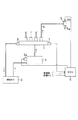
図1はインジェクタの噴射量と指令噴射パルス期間との相関を示す噴射特性(Tq−Qt線図)と、その近似式を示すマップである。
本実施例の燃料噴射システムは、例えば4気筒のディーゼル機関(図示しない)に適用されるもので、図2に示す様に、燃料を高圧状態で蓄えるコモンレール1と、燃料タンク2から汲み上げられた燃料を加圧してコモンレール1に圧送する高圧ポンプ3と、コモンレール1より高圧配管4を通って供給される高圧燃料をディーゼル機関の気筒内に噴射するインジェクタ5等を備え、ECU6(本発明の制御手段)により制御される。
【0015】
コモンレール1には、コモンレール1内の燃料圧力を検出してECU6に出力する圧力センサ7と、コモンレール1内の燃料圧力が予め設定された上限値を超えないように制限するプレッシャリミッタ8が取り付けられている。
高圧ポンプ3は、燃料タンク2から汲み上げられた燃料をポンプ室(図示しない)に導入する燃料通路(図示しない)に電磁調量弁3aが設けられ、ポンプ室に内蔵されるプランジャの上昇中に電磁調量弁3aが燃料通路を遮断すると、ポンプ室の燃料がプランジャによって加圧され、図示しない逆止弁を押し開いてコモンレール1へ高圧燃料を圧送する。
【0016】
インジェクタ5は、ニードル(図示しない)を内蔵するノズル5aと、ピエゾ素子(図示しない)を用いてニードルの背圧を制御する駆動弁5bとを有し、この駆動弁5bの通電時にノズル5aより燃料噴射を行う。具体的には、駆動弁5bに通電すると、ノズル5aの背後に設けられる圧力制御室の燃料圧力が低下するため、ニードルが上昇して噴射が開始される。その後、駆動弁5bへの通電を停止すると、圧力制御室の燃料圧力が上昇するため、ニードルが押し下げられて噴射が終了する。従って、駆動弁5bへの通電時期により噴射時期が制御され、駆動弁5bへの通電期間(指令噴射パルス期間)により噴射量が制御される。
【0017】
このインジェクタ5は、メモリ等の記憶媒体(例えばQRコード:本発明の近似式記憶手段)を搭載し、この記憶媒体には、噴射圧力Pcに応じて噴射量Qtと噴射パルス期間Tqとの相関を示す噴射特性の近似式が記憶されている。
なお、本実施例のインジェクタ5は、ノズル5aのニードル開弁速度が速く、フルリフト領域を使用するものであり、図1に示す様に、噴射特性に変曲点が現れる。
ここで、噴射特性の近似式について説明する。
インジェクタ5の組み付け完了後に、例えば3段階の噴射圧力(高圧、中圧、低圧)で、それぞれ噴射量と噴射パルス期間との相関を示す噴射特性のデータを何点か計測する。
【0018】
続いて、変曲点より噴射パルス期間Tqが小さい領域と大きい領域とで、それぞれ複数の実測データより、そのデータ上を通過する近似式を立てる。
ここで、近似式が1次式の場合は、次式▲1▼で表される様に、未知数がaとbの二つであることから、データは2点必要となる。
y=ax+b(Qt=a・Tq+b)……………………………………▲1▼
また、2次式の場合は、次式▲2▼で表される様に、未知数がa、b、cの三つであることから、データは3点必要となる。
y=ax2 +bx+c(Qt=a・Tq2 +b・Tq+c)…………▲2▼
【0019】
なお、変曲点より噴射パルス期間Tqが大きい領域では、噴射特性が略直線を示しているので、1次式が適当である。
また、近似式の数は、変曲点の数が1つとは限らないため、変曲点の数+1の式が必要となり、それを測定圧力毎に算出する(図1参照)。
算出された各近似式の係数a、b、c…をインジェクタ5に搭載されたメモリに記憶させ、インジェクタ5毎に出荷出来るようにする。
【0020】
ECU6は、ディーゼル機関の運転状態などを検出する各種センサから入力される情報に基づいてインジェクタ5の噴射時期及び要求噴射量を算出し、これらの演算結果に従ってインジェクタ5の駆動弁5bを電子制御する。
このECU6は、インジェクタ5の機種に共通な基準となる噴射特性(基準噴射特性)の実測データをコモンレール1の圧力に応じて細かく記録した基準マップ(本発明の基準噴射特性記憶手段)を有している。なお、この基準噴射特性にもインジェクタ5の噴射特性と同様に変曲点が存在する(図4参照)。
また、ECU6は、上述したインジェクタ5の場合と同様の方法で算出された基準噴射特性の近似式(基準近似式)がメモリ(本発明の基準近似式記憶手段)に記憶されている。
【0021】
次に、実際の噴射時にECU6が行う演算について、図3に示すフローチャートを基に説明する。
Step10…インジェクタ5のメモリに記憶された各近似式の係数(a、b、c…)を読み込む。
Step20…圧力P1 で要求された噴射量Qtに対して、図4に示す基準マップ上の実測データより基準Tqを求める。
Step30…基準近似式に基準Tqを代入して基準噴射量Qkを求める。
【0022】
Step40…圧力P1 におけるインジェクタ5の近似式を求める。
例えば、変曲点が1点の場合、近似式は以下の2本(第1の近似式と第2の近似式)であり、各式の係数を求める。
y=aP1・x+bP1…(第1の近似式)
y=cP1・x+dP1…(第2の近似式)
係数(aP1、bP1、cP1、dP1)は、インジェクタ5の仕様により一様の傾向があり、例えば図5の様になる。よって、この傾向を式またはマップとしてECU6に記憶させておけば、各圧力に対する近似式の係数(a、b、c、d)が求められる。
【0023】
Step50…基準噴射量Qkに対する噴射パルス期間Tqを求める。
具体的には、上記Step40で求めた2本の近似式より逆関数(xについて解いた式)を求め、その逆関数のy項に基準噴射量Qkを代入して算出される値(x1 、x2 )=(TqA、TqB)を比較し、大きい方の値TqB(図4参照)を指令噴射パルス期間とする。
この指令噴射パルス期間TqBでインジェクタ5を駆動すると、実際の噴射特性に対する実噴射量Qで噴射し、要求噴射量Qtに対して近い噴射量で噴射することができる。
【0024】
(本実施例の効果)
本実施例では、個々のインジェクタ5に対して、噴射特性の実測データから算出された第1の近似式と第2の近似式とが交わる点を変曲点として求めることができる。その結果、要求噴射量に対して指令噴射パルス期間を求める際に、マップ上に記録された粗い実測データから補間計算する従来の方法と比較して、変曲点付近の補正精度が向上する。例えば、図4に示す様に、基準近似式では変曲点より小さいTq領域に要求噴射量が与えられるのに対し、実際のインジェクタ5では変曲点より大きいTq領域で実噴射量が求められているが、変曲点の位置が精度良く算出されることにより、変曲点付近の補正精度が他の領域に比べて極端に悪くなることがない。
【0025】
また、図6に示す様に、要求噴射量と実噴射量とが、変曲点に対して同じTq領域にある場合も同様に補正精度が向上する。これは、一般にうねりが噴射開始から起こり、同周期の振動となるため、振動の中心を通る近似式がTq方向にずれると同位相に近づくことから、基準噴射量Qkにうねり分がコピーされて、補正精度を高める一因となっている。
【0026】
(変形例)
上記の実施例では、インジェクタ5の噴射特性にうねりが生じる場合を示しているが、噴射特性が略直線的に変化する場合(うねりが現れない状態)は、近似式が噴射特性と略一致するため、要求噴射量に対する指令噴射パルス期間を近似式から直接求めることができる。
また、上記の実施例では、インジェクタ5の噴射特性に変曲点が存在することを前提に説明しているが、変曲点が存在しない場合、つまり噴射特性の近似式が1つの式y=ax+bで示される場合にも本発明を適用することができる。
また、インジェクタ5に使用される駆動弁5bは、ピエゾ素子による駆動形式以外にも、例えばソレノイドを用いた電磁弁でも良い。
【図面の簡単な説明】
【図1】インジェクタの噴射特性と近似式を示す特性図である。
【図2】燃料噴射システムの全体構成図である。
【図3】指令噴射パルス期間の算出手順を示すフローチャートである。
【図4】要求噴射量に対する指令噴射パルス期間を求めるための特性図である。
【図5】近似式の係数と圧力との関係を示す相関図である。
【図6】基準噴射特性とインジェクタの噴射特性のうねりを比較した特性図である。
【符号の説明】
5 インジェクタ
6 ECU(制御手段)[0001]
BACKGROUND OF THE INVENTION
The present invention relates to a fuel injection system including an injector that injects fuel into a cylinder of an internal combustion engine.
[0002]
[Prior art]
2. Description of the Related Art Conventionally, as a fuel injection system for a diesel engine, a pressure accumulation type fuel injection system that injects high-pressure fuel stored in a common rail into a cylinder of the diesel engine from an injector is known.
An injector used in this fuel injection system is required to have high metering accuracy under a high pressure of, for example, 100 MPa or more. However, since individual injectors vary in injection amount due to individual differences (referred to as individual variations), it is necessary to correct the individual variations in injectors in order to achieve high metering accuracy.
[0003]
The conventional method of correcting the individual variation is to record the injection amount of each injector as a measured value on a map with the injection pressure (hereinafter referred to as Pc) × commanded injection pulse period (hereinafter referred to as Tq) as coordinate axes. The actually measured data is read into the in-vehicle ECU (injection control CPU). Then, at each injection, how much Tq should be increased or decreased with respect to the required injection amount is obtained by interpolation calculation from actual measurement data recorded on the previous map.
[0004]
[Problems to be solved by the invention]
The above correction method is accurate and relatively simple logic for an injector in which Tq changes linearly with respect to the required injection amount (hereinafter Qt) (no inflection point appears on the Tq-Qt diagram). Correction was possible. However, in an injector having a fast nozzle opening speed of the nozzle (for example, an injector using the full lift region of the nozzle), an inflection point appears on the Tq-Qt diagram before and after the full lift. Before and after the inflection point, the rate of increase of Tq with respect to Qt (straight line) changes, so that the correction accuracy near the inflection point is extremely deteriorated.
[0005]
The present invention has been made on the basis of the above circumstances, and its purpose is to clarify the position of an inflection point appearing on a Tq-Qt diagram when correcting the variation of injectors among individuals. Another object of the present invention is to provide a fuel injection system capable of improving the correction accuracy near the inflection point.
[0006]
[Means for Solving the Problems]
(Invention of Claim 1)
The fuel injection system according to the present invention includes an injector that injects fuel into a cylinder of an internal combustion engine, and an approximate expression that stores an approximate expression of an injection characteristic that indicates a correlation between an injection amount corresponding to an injection pressure of the injector and an injection pulse period. It has a storage means and a control means for controlling the operation of the injector based on the command injection pulse period, and this control means calculates the command injection pulse period from the approximate expression for the required injection amount. .
[0007]
According to the present invention, when calculating the command injection pulse period for the required injection amount, it is not necessary to perform interpolation calculation from the actual measurement data of the injection characteristics recorded on the map as in the prior art, and the approximate expression of the injection characteristics Therefore, the calculation of the control means can be simplified.
In addition, when the injection characteristic of the injector changes substantially linearly (in a state where no periodic undulation appears), the approximate expression is approximately the same as the injection characteristic, so the command injection pulse period for the required injection amount can be accurately determined from the approximate expression. You can ask well.
Further, in the present invention, the control means stores a reference injection characteristic storage means for storing a reference injection characteristic serving as a reference common to injector models, and a reference approximate expression for storing a reference approximate expression calculated from actually measured data of the reference injection characteristics. A reference command injection pulse period from the reference injection characteristic for the required injection amount, and substituting the reference command injection pulse period into a reference approximate expression to calculate a reference injection amount, A command injection pulse period with respect to the reference injection amount is obtained from the above.
According to this configuration, since the deviation (waviness) between the reference injection characteristic common to the injector model and the reference approximate expression is reflected in the approximate expression, even when periodic undulation appears in the injection characteristic of the injector High correction accuracy can be maintained.
[0008]
(Invention of Claim 2)
The fuel injection system according to the present invention includes an injector that injects fuel into a cylinder of an internal combustion engine, and an approximate expression that stores an approximate expression of an injection characteristic that indicates a correlation between an injection amount corresponding to an injection pressure of the injector and an injection pulse period. Storage means and control means for controlling the operation of the injector based on the command injection pulse period. This control means is a fuel injection system that calculates the command injection pulse period from the approximate expression for the required injection amount. Thus, the approximate expression stored in the approximate expression storage means is that when there is an inflection point in the injection characteristic of the injector, there are a plurality of measured data respectively for the region where the injection pulse period is smaller and larger than the inflection point. The first approximate expression and the second approximate expression calculated from
In this case, since the position of the inflection point can be accurately calculated by the first approximate expression and the second approximate expression (the point at which the first approximate expression and the second approximate expression intersect is used as the inflection point), When obtaining the command injection pulse period for the required injection amount, the correction accuracy near the inflection point is improved as compared with the conventional method in which interpolation calculation is performed from actually measured data recorded on the map.
Further, in the present invention, when the control means has a reference injection characteristic storage means for storing a reference injection characteristic serving as a reference common to the model of the injector, and an inflection point exists in the reference injection characteristic, from the inflection point A first reference approximate expression and a second reference approximate expression are calculated from a plurality of actually measured data in a region where the injection pulse period is small and a region where the injection pulse period is large, and the first reference approximate equation and the second reference approximate equation are calculated. And a reference approximate expression storage means for storing the reference command injection pulse period from the reference injection characteristic with respect to the required injection amount, and the reference command injection pulse period is determined as the first reference approximate expression or the second reference. After calculating the reference injection amount by substituting into the approximate expression, a command injection pulse period for the reference injection amount is further obtained from the first approximate expression or the second approximate expression.
According to this configuration, the deviation (undulation) between the reference injection characteristic common to the injector model and the first reference approximate expression or the second reference approximate expression is the first approximate expression or the second approximate expression. Therefore, even when periodic undulation appears in the injection characteristics of the injector, high correction accuracy can be maintained.
[0013]
(Invention of Claim 3 )
In fuel injection system of
The approximate expression storage means is a memory mounted on an injector. In this case, since the correspondence between the individual injectors and the data of the approximate equations is ensured, a highly reliable fuel injection system can be realized.
[0014]
DETAILED DESCRIPTION OF THE INVENTION
Next, embodiments of the present invention will be described with reference to the drawings.
FIG. 1 is a map showing an injection characteristic (Tq-Qt diagram) showing a correlation between an injection amount of an injector and a command injection pulse period and an approximate expression thereof.
The fuel injection system of this embodiment is applied to, for example, a four-cylinder diesel engine (not shown). As shown in FIG. 2, the fuel injection system is pumped up from a common rail 1 for storing fuel in a high pressure state and a
[0015]
A
The high-
[0016]
The
[0017]
The
The
Here, an approximate expression of the injection characteristic will be described.
After completing the assembly of the
[0018]
Subsequently, an approximate expression that passes over the data is established from a plurality of measured data in a region where the injection pulse period Tq is smaller and a region larger than the inflection point.
Here, when the approximate expression is a linear expression, since the unknowns are two, a and b, as shown by the following expression (1), two points of data are required.
y = ax + b (Qt = a · Tq + b) …………………………………… ▲ 1 ▼
In the case of a quadratic expression, as represented by the following expression (2), since there are three unknowns a, b, and c, three points of data are required.
y = ax 2 + bx + c (Qt = a · Tq 2 + b · Tq + c) ………… (2)
[0019]
Note that in the region where the injection pulse period Tq is longer than the inflection point, the injection characteristic shows a substantially straight line, so the linear expression is appropriate.
In addition, since the number of inflection points is not necessarily one, the number of inflection points is calculated by the number of inflection points + 1, which is calculated for each measurement pressure (see FIG. 1).
The calculated coefficients a, b, c... Of each approximate expression are stored in a memory mounted on the
[0020]
The
This
Further, the
[0021]
Next, calculations performed by the
Step 10... The coefficients (a, b, c...) Of each approximate expression stored in the memory of the
Step 20: The reference Tq is obtained from the actually measured data on the reference map shown in FIG. 4 for the injection amount Qt requested at the pressure P1.
Step 30: Substituting the reference Tq into the reference approximate expression to obtain the reference injection amount Qk.
[0022]
Step 40: An approximate expression of the
For example, when there is one inflection point, there are the following two approximate expressions (first approximate expression and second approximate expression), and the coefficient of each expression is obtained.
y = a P1 · x + b P1 (first approximate expression)
y = c P1 · x + d P1 (second approximate expression)
The coefficients (a P1 , b P1 , c P1 , d P1 ) tend to be uniform depending on the specifications of the
[0023]
Step 50: An injection pulse period Tq with respect to the reference injection amount Qk is obtained.
Specifically, an inverse function (an expression solved for x) is obtained from the two approximate expressions obtained in Step 40 above, and a value (x 1) calculated by substituting the reference injection amount Qk into the y term of the inverse function. , X 2 ) = (TqA, TqB), and the larger value TqB (see FIG. 4) is set as the command injection pulse period.
When the
[0024]
(Effect of this embodiment)
In the present embodiment, for each
[0025]
Further, as shown in FIG. 6, the correction accuracy is also improved when the required injection amount and the actual injection amount are in the same Tq region with respect to the inflection point. This is because the undulation generally occurs from the start of injection and becomes a vibration of the same period, so that the approximate expression passing through the center of the vibration approaches the same phase when shifted in the Tq direction. This is one reason for improving the correction accuracy.
[0026]
(Modification)
In the above embodiment, the case where the swell occurs in the injection characteristic of the
Further, in the above-described embodiment, the description has been made on the assumption that the injection characteristic of the
Further, the
[Brief description of the drawings]
FIG. 1 is a characteristic diagram showing an injection characteristic and an approximate expression of an injector.
FIG. 2 is an overall configuration diagram of a fuel injection system.
FIG. 3 is a flowchart showing a procedure for calculating a command injection pulse period.
FIG. 4 is a characteristic diagram for obtaining a command injection pulse period with respect to a required injection amount.
FIG. 5 is a correlation diagram showing the relationship between the coefficient of the approximate expression and the pressure.
FIG. 6 is a characteristic diagram comparing the swell of the reference injection characteristic and the injection characteristic of the injector.
[Explanation of symbols]
5
Claims (3)
このインジェクタの噴射圧力に応じた噴射量と噴射パルス期間との相関を示す噴射特性の近似式を記憶する近似式記憶手段と、
指令噴射パルス期間に基づいて前記インジェクタの作動を制御する制御手段とを有し、
前記制御手段は、要求噴射量に対して前記近似式から前記指令噴射パルス期間を算出する燃料噴射システムであって、
前記制御手段は、
a)前記インジェクタの機種に共通な基準となる噴射特性(基準噴射特性)を記憶する基準噴射特性記憶手段と、
b)前記基準噴射特性の実測データから算出した基準近似式を記憶する基準近似式記憶手段とを有し、
前記要求噴射量に対して前記基準噴射特性から基準指令噴射パルス期間を求め、この基準指令噴射パルス期間を前記基準近似式に代入して基準噴射量を算出した後、更に前記近似式から前記基準噴射量に対する指令噴射パルス期間を求めることを特徴とする燃料噴射システム。 An injector for injecting fuel into a cylinder of the internal combustion engine;
An approximate expression storage means for storing an approximate expression of an injection characteristic indicating a correlation between an injection amount according to an injection pressure of the injector and an injection pulse period;
Based on the command injection pulse duration have a control means for controlling the operation of the injector,
Wherein said control means is a fuel injection system that calculates the command injection pulse duration from the approximate expression for the request injection quantity,
The control means includes
a) reference injection characteristic storage means for storing an injection characteristic (reference injection characteristic) serving as a reference common to the injector models;
b) reference approximate expression storage means for storing a reference approximate expression calculated from the actual measurement data of the reference injection characteristics;
A reference command injection pulse period is obtained from the reference injection characteristic with respect to the required injection quantity, and the reference injection quantity is calculated by substituting the reference command injection pulse period into the reference approximate expression. A fuel injection system for obtaining a command injection pulse period for an injection amount.
このインジェクタの噴射圧力に応じた噴射量と噴射パルス期間との相関を示す噴射特性の近似式を記憶する近似式記憶手段と、
指令噴射パルス期間に基づいて前記インジェクタの作動を制御する制御手段とを有し、
前記制御手段は、要求噴射量に対して前記近似式から前記指令噴射パルス期間を算出する燃料噴射システムであって、
前記近似式記憶手段に記憶される近似式は、前記インジェクタの噴射特性に変曲点が存在する場合に、その変曲点より噴射パルス期間が小さい領域と大きい領域とで、それぞれ複数の実測データから算出される第1の近似式と第2の近似式であり、
前記制御手段は、
a)前記インジェクタの機種に共通な基準となる噴射特性(基準噴射特性)を記憶する基準噴射特性記憶手段と、
b)前記基準噴射特性に変曲点が存在する場合に、その変曲点より噴射パルス期間が小さい領域と大きい領域とで、それぞれ複数の実測データから第1の基準近似式と第2の基準近似式とを算出し、その第1の基準近似式と第2の基準近似式とを記憶する基準近似式記憶手段とを有し、
前記要求噴射量に対して前記基準噴射特性から基準指令噴射パルス期間を求め、この基準指令噴射パルス期間を前記第1の基準近似式または前記第2の基準近似式に代入して基準噴射量を算出した後、更に前記第1の近似式または前記第2の近似式から前記基準噴射量に対する指令噴射パルス期間を求めることを特徴とする燃料噴射システム。 An injector for injecting fuel into a cylinder of the internal combustion engine;
An approximate expression storage means for storing an approximate expression of an injection characteristic indicating a correlation between an injection amount according to an injection pressure of the injector and an injection pulse period;
Control means for controlling the operation of the injector based on a command injection pulse period;
The control means is a fuel injection system that calculates the command injection pulse period from the approximate expression with respect to a required injection amount,
When the inflection point exists in the injection characteristic of the injector, the approximate expression stored in the approximate expression storage means includes a plurality of actually measured data in a region where the injection pulse period is smaller and larger than the inflection point. first approximate expression and the second approximate expression der calculated from is,
The control means includes
a) reference injection characteristic storage means for storing an injection characteristic (reference injection characteristic) serving as a reference common to the injector models;
b) When an inflection point exists in the reference injection characteristic, a first reference approximate expression and a second reference are obtained from a plurality of actually measured data in an area where the injection pulse period is smaller and larger than the inflection point, respectively. A reference approximate expression storage means for calculating the approximate expression and storing the first reference approximate expression and the second reference approximate expression;
A reference command injection pulse period is obtained from the reference injection characteristic with respect to the required injection quantity, and this reference command injection pulse period is substituted into the first reference approximate expression or the second reference approximate expression to obtain a reference injection quantity. After the calculation , a fuel injection system, wherein a command injection pulse period for the reference injection amount is further obtained from the first approximate expression or the second approximate expression .
前記近似式記憶手段は、前記インジェクタに搭載されるメモリであることを特徴とする燃料噴射システム。 The fuel injection system according to claim 1 or 2 ,
The fuel injection system according to claim 1, wherein the approximate expression storage means is a memory mounted on the injector .
Priority Applications (2)
| Application Number | Priority Date | Filing Date | Title |
|---|---|---|---|
| JP2002178007A JP4061982B2 (en) | 2002-06-19 | 2002-06-19 | Fuel injection system |
| DE10327533.9A DE10327533B4 (en) | 2002-06-19 | 2003-06-18 | Fuel injection system |
Applications Claiming Priority (1)
| Application Number | Priority Date | Filing Date | Title |
|---|---|---|---|
| JP2002178007A JP4061982B2 (en) | 2002-06-19 | 2002-06-19 | Fuel injection system |
Publications (2)
| Publication Number | Publication Date |
|---|---|
| JP2004019602A JP2004019602A (en) | 2004-01-22 |
| JP4061982B2 true JP4061982B2 (en) | 2008-03-19 |
Family
ID=29996501
Family Applications (1)
| Application Number | Title | Priority Date | Filing Date |
|---|---|---|---|
| JP2002178007A Expired - Fee Related JP4061982B2 (en) | 2002-06-19 | 2002-06-19 | Fuel injection system |
Country Status (2)
| Country | Link |
|---|---|
| JP (1) | JP4061982B2 (en) |
| DE (1) | DE10327533B4 (en) |
Families Citing this family (4)
| Publication number | Priority date | Publication date | Assignee | Title |
|---|---|---|---|---|
| DE102006007076A1 (en) | 2006-02-15 | 2007-08-16 | Siemens Ag | Injection system for an internal combustion engine and internal combustion engine |
| DE102006007786B3 (en) | 2006-02-20 | 2007-06-21 | Siemens Ag | Fuel injection quantity control parameters estimating method for piezo injection system, involves finding injection control grid with grid points, finding test points and estimating parameters using limited linear regression between points |
| JP6217396B2 (en) * | 2014-01-06 | 2017-10-25 | 株式会社デンソー | Fuel injection control device |
| JP2017031939A (en) * | 2015-08-05 | 2017-02-09 | 株式会社デンソー | Electromagnetic valve drive unit |
Family Cites Families (2)
| Publication number | Priority date | Publication date | Assignee | Title |
|---|---|---|---|---|
| DE19540416A1 (en) | 1995-10-30 | 1997-05-07 | Bayerische Motoren Werke Ag | Device for the electronic control of the internal combustion engine in motor vehicles with an injection valve |
| AT2164U3 (en) | 1997-08-07 | 1999-02-25 | Avl List Gmbh | INJECTION NOZZLE FOR A DIRECTLY INJECTING INTERNAL COMBUSTION ENGINE |
-
2002
- 2002-06-19 JP JP2002178007A patent/JP4061982B2/en not_active Expired - Fee Related
-
2003
- 2003-06-18 DE DE10327533.9A patent/DE10327533B4/en not_active Expired - Fee Related
Also Published As
| Publication number | Publication date |
|---|---|
| DE10327533B4 (en) | 2018-06-21 |
| DE10327533A1 (en) | 2004-01-29 |
| JP2004019602A (en) | 2004-01-22 |
Similar Documents
| Publication | Publication Date | Title |
|---|---|---|
| US6142121A (en) | Method and device for fuel injection of engine | |
| US7255087B2 (en) | Method for controlling an injection system of an internal combustion engine | |
| US7913666B2 (en) | Method and device for controlling an injection valve of an internal combustion engine | |
| JP4678397B2 (en) | Fuel injection state detection device | |
| US7201148B2 (en) | Pressure accumulation fuel injection controller | |
| EP1668235B1 (en) | Fuel injection control apparatus for internal combustion engine | |
| US6311669B1 (en) | Method for determining the injection time in a direct-injection internal combustion engine | |
| KR101033062B1 (en) | Device and method for correction of the injection behaviour of an injector | |
| JP4555513B2 (en) | Method for defining a control voltage for a piezoelectric actuator of an injection valve | |
| JP5723244B2 (en) | Fuel injection control device | |
| JP4118652B2 (en) | Accumulated fuel injection system | |
| KR20100051623A (en) | Method for the determination of an injected fuel mass of a preinjection | |
| JP4061982B2 (en) | Fuel injection system | |
| JP2011007203A (en) | Fuel injection state detector | |
| JP5024430B2 (en) | Fuel injection control device | |
| WO2019225546A1 (en) | Fuel injection valve control device and control method for same | |
| JP2009057853A (en) | Fuel injection control device and fuel injection quantity learning method of internal combustion engine | |
| JP6028603B2 (en) | Fuel injection state estimation device | |
| JP2011256839A (en) | Pressure-accumulation fuel injection device and control device of the same | |
| JP2009097501A (en) | Controller for fuel injection system | |
| JP6507982B2 (en) | Fuel injection state detection device | |
| WO2011039889A1 (en) | Spray control device, spray control method, and target spray amount correction method | |
| JP7021595B2 (en) | Fuel passage characteristic acquisition device | |
| JP2005163559A (en) | Accumulator fuel injection device | |
| JP5229965B2 (en) | Fuel injection control device |
Legal Events
| Date | Code | Title | Description |
|---|---|---|---|
| A621 | Written request for application examination |
Free format text: JAPANESE INTERMEDIATE CODE: A621 Effective date: 20040712 |
|
| A977 | Report on retrieval |
Free format text: JAPANESE INTERMEDIATE CODE: A971007 Effective date: 20070403 |
|
| A131 | Notification of reasons for refusal |
Free format text: JAPANESE INTERMEDIATE CODE: A131 Effective date: 20070907 |
|
| A521 | Written amendment |
Free format text: JAPANESE INTERMEDIATE CODE: A523 Effective date: 20071102 |
|
| TRDD | Decision of grant or rejection written | ||
| A01 | Written decision to grant a patent or to grant a registration (utility model) |
Free format text: JAPANESE INTERMEDIATE CODE: A01 Effective date: 20071204 |
|
| A61 | First payment of annual fees (during grant procedure) |
Free format text: JAPANESE INTERMEDIATE CODE: A61 Effective date: 20071217 |
|
| R150 | Certificate of patent or registration of utility model |
Free format text: JAPANESE INTERMEDIATE CODE: R150 |
|
| FPAY | Renewal fee payment (event date is renewal date of database) |
Free format text: PAYMENT UNTIL: 20110111 Year of fee payment: 3 |
|
| FPAY | Renewal fee payment (event date is renewal date of database) |
Free format text: PAYMENT UNTIL: 20120111 Year of fee payment: 4 |
|
| FPAY | Renewal fee payment (event date is renewal date of database) |
Free format text: PAYMENT UNTIL: 20130111 Year of fee payment: 5 |
|
| FPAY | Renewal fee payment (event date is renewal date of database) |
Free format text: PAYMENT UNTIL: 20140111 Year of fee payment: 6 |
|
| R250 | Receipt of annual fees |
Free format text: JAPANESE INTERMEDIATE CODE: R250 |
|
| R250 | Receipt of annual fees |
Free format text: JAPANESE INTERMEDIATE CODE: R250 |
|
| R250 | Receipt of annual fees |
Free format text: JAPANESE INTERMEDIATE CODE: R250 |
|
| LAPS | Cancellation because of no payment of annual fees |