JP4515487B2 - Control device for fuel injector and method for operating fuel injector - Google Patents
Control device for fuel injector and method for operating fuel injector Download PDFInfo
- Publication number
- JP4515487B2 JP4515487B2 JP2007136349A JP2007136349A JP4515487B2 JP 4515487 B2 JP4515487 B2 JP 4515487B2 JP 2007136349 A JP2007136349 A JP 2007136349A JP 2007136349 A JP2007136349 A JP 2007136349A JP 4515487 B2 JP4515487 B2 JP 4515487B2
- Authority
- JP
- Japan
- Prior art keywords
- control device
- voltage
- injector
- pressure wave
- actuator
- Prior art date
- Legal status (The legal status is an assumption and is not a legal conclusion. Google has not performed a legal analysis and makes no representation as to the accuracy of the status listed.)
- Expired - Fee Related
Links
- 239000000446 fuel Substances 0.000 title claims description 46
- 238000000034 method Methods 0.000 title claims description 16
- 238000002347 injection Methods 0.000 claims description 61
- 239000007924 injection Substances 0.000 claims description 61
- 238000013500 data storage Methods 0.000 claims description 4
- 230000004044 response Effects 0.000 claims description 3
- 230000009849 deactivation Effects 0.000 claims description 2
- 230000000694 effects Effects 0.000 description 7
- 238000002485 combustion reaction Methods 0.000 description 6
- 230000008859 change Effects 0.000 description 3
- 238000000926 separation method Methods 0.000 description 3
- 230000002123 temporal effect Effects 0.000 description 2
- 230000008901 benefit Effects 0.000 description 1
- 230000005540 biological transmission Effects 0.000 description 1
- 230000004048 modification Effects 0.000 description 1
- 238000012986 modification Methods 0.000 description 1
- 230000010355 oscillation Effects 0.000 description 1
- 230000003252 repetitive effect Effects 0.000 description 1
- 239000000243 solution Substances 0.000 description 1
Images


Classifications
-
- F—MECHANICAL ENGINEERING; LIGHTING; HEATING; WEAPONS; BLASTING
- F02—COMBUSTION ENGINES; HOT-GAS OR COMBUSTION-PRODUCT ENGINE PLANTS
- F02D—CONTROLLING COMBUSTION ENGINES
- F02D41/00—Electrical control of supply of combustible mixture or its constituents
- F02D41/20—Output circuits, e.g. for controlling currents in command coils
- F02D41/2096—Output circuits, e.g. for controlling currents in command coils for controlling piezoelectric injectors
-
- F—MECHANICAL ENGINEERING; LIGHTING; HEATING; WEAPONS; BLASTING
- F02—COMBUSTION ENGINES; HOT-GAS OR COMBUSTION-PRODUCT ENGINE PLANTS
- F02D—CONTROLLING COMBUSTION ENGINES
- F02D2250/00—Engine control related to specific problems or objectives
- F02D2250/04—Fuel pressure pulsation in common rails
-
- F—MECHANICAL ENGINEERING; LIGHTING; HEATING; WEAPONS; BLASTING
- F02—COMBUSTION ENGINES; HOT-GAS OR COMBUSTION-PRODUCT ENGINE PLANTS
- F02D—CONTROLLING COMBUSTION ENGINES
- F02D41/00—Electrical control of supply of combustible mixture or its constituents
- F02D41/30—Controlling fuel injection
- F02D41/38—Controlling fuel injection of the high pressure type
- F02D41/40—Controlling fuel injection of the high pressure type with means for controlling injection timing or duration
- F02D41/402—Multiple injections
- F02D41/403—Multiple injections with pilot injections
Description
本発明は、一つの燃料噴射器用制御装置及び一つの燃料噴射器を作動する方法に関する。更に詳細には、本発明は、パイロット燃料噴射事象の一貫性を改善するため、一つの圧電作動式燃料噴射器を作動する方法に関する。 The present invention relates to a method of operating a single fuel injectors controller and one fuel injector. More particularly, the present invention relates to a method of operating a single piezoelectric actuated fuel injector to improve the consistency of pilot fuel injection events.
内燃エンジンに関し、燃料噴射器によって燃料をエンジンのシリンダに送出することは周知である。燃料の送出を正確に計量できる、一つのこのような種類の燃料噴射器は、いわゆる「圧電噴射器」である。 For internal combustion engines, it is well known to deliver fuel to a cylinder of the engine by a fuel injector. One such type of fuel injector that can accurately meter fuel delivery is a so-called “piezoelectric injector”.
図1を参照すると、圧電噴射器2は、圧電アクチュエータ4を含む。この圧電アクチュエータ4は、噴射器バルブニードル6の位置をバルブニードル座8に対して制御するように作動できる。圧電アクチュエータ4に加わる駆動電圧分布「V」に応じて、バルブニードル6を、バルブニードル座8と係合した状態から外すか或いは、バルブニードル座8と係合させるかのいずれかである。バルブニードル座8と係合した状態から外れた場合には、燃料が、一組のノズル出口10を通って、関連した燃焼室(図示せず)内に送出される。バルブニードル座8と係合させた場合には、燃料の送出が阻止される。
Referring to FIG. 1, the piezoelectric injector 2 includes a piezoelectric actuator 4. This piezoelectric actuator 4 is operable to control the position of the injector valve needle 6 relative to the valve needle seat 8. Depending on the drive voltage distribution “V” applied to the piezoelectric actuator 4, either the valve needle 6 is removed from the engaged state with the valve needle seat 8 or is engaged with the valve needle seat 8. When out of engagement with the valve needle seat 8, fuel is delivered through a set of
圧電噴射器は、エンジン制御ユニット(ECU)22の一体の部分を形成する噴射器制御ユニット(ICU)20によって制御される。ECU22は、複数のエンジンパラメータ24を監視し、エンジン出力要求信号をICU20に供給する。ICU20は、必要な噴射事象順序を(プロセッサ21を使用して)計算し、必要な出力をエンジンに提供し、電圧パルス分布25を噴射器駆動回路26に出力する。噴射器駆動回路26は、高圧側電圧信号VHI及び低圧側電圧信号VLOを介して電圧駆動分布25を噴射器に印加する。
The piezoelectric injector is controlled by an injector control unit (ICU) 20 that forms an integral part of an engine control unit (ECU) 22. The ECU 22 monitors a plurality of
噴射を開始するため、駆動回路26により、VHIとVLOとの間の差動電圧を、燃料の送出が行われない場合の高電圧(代表的には250V)から、燃料の送出を開始する比較的低い電圧(代表的には50V)まで変化する。
In order to start the injection, the
この駆動波形に応答する噴射器を「消勢噴射」噴射器と呼ぶ。 An injector that responds to this drive waveform is referred to as a “de-energized” injector.
このような燃料噴射器は、一回の噴射事象内で一回又はそれ以上の燃料噴射を送出するように作動できる。例えば、噴射事象は、一回又はそれ以上のいわゆる「予備」噴射又は「パイロット」噴射、主噴射、及び一回又はそれ以上の「後」噴射が含まれていてもよい。一般的には、一回の噴射事象内での幾つかのこのような噴射を行うことは、エンジンの燃焼効率を向上するため、好ましい。 Such fuel injectors can be operated to deliver one or more fuel injections within a single injection event. For example, an injection event may include one or more so-called “preliminary” or “pilot” injections, a main injection, and one or more “post” injections. In general, performing several such injections within a single injection event is preferred because it improves the combustion efficiency of the engine.
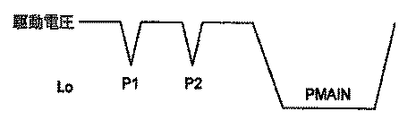
噴射事象中に噴射器に印加される代表的な噴射器駆動電圧分布を図2に示し、対応する理想的送出量分布を図3に示す。 A typical injector drive voltage distribution applied to the injector during an injection event is shown in FIG. 2, and the corresponding ideal delivery volume distribution is shown in FIG.
噴射器駆動電圧分布は、第1及び第2のパイロット放電パルスP1及びP2と、単一の主噴射放電パルスPMAINとを含む。パイロット放電パルスP1、P2の大きさ及び持続時間は、実質的に同じである。従って、各パイロット噴射P1、P2の各々についての送出量は実質的に等しく、及びかくして送出された燃料の容積(距離の下の面積)は、パイロット噴射間で一貫している。 The injector drive voltage distribution includes first and second pilot discharge pulses P1 and P2 and a single main injection discharge pulse PMAIN. The magnitude and duration of the pilot discharge pulses P1, P2 are substantially the same. Thus, the delivery for each pilot injection P1, P2 is substantially equal, and thus the volume of fuel delivered (area under the distance) is consistent between pilot injections.
しかしながら、同じ電圧放電分布についてのパイロット噴射間の実際の送出量は大幅に変化することが観察された。例えば、図4は、実際に観察された燃料送出量分布を示し、この分布では、第2パイロット噴射について送出された燃料が、第1パイロット噴射中に送出された燃料よりも多い。 However, it has been observed that the actual delivery between pilot injections for the same voltage discharge distribution varies significantly. For example, FIG. 4 shows an actually observed fuel delivery volume distribution, where more fuel is delivered for the second pilot injection than fuel delivered during the first pilot injection.
パイロット噴射の目的は、燃焼プロセスを徐々に開始するため、主噴射前に正確な量の燃料を燃焼室に送出することである。従って、パイロット噴射間で燃料送出量が変化することは望ましくない。これは、燃焼プロセスの制御性を低下するためである。従って、パイロット噴射間に送出される燃料の容積を調節する方法が必要とされている。 The purpose of the pilot injection is to deliver the correct amount of fuel to the combustion chamber before the main injection in order to gradually start the combustion process. Therefore, it is undesirable for the fuel delivery amount to change between pilot injections. This is to reduce the controllability of the combustion process. Accordingly, there is a need for a method for adjusting the volume of fuel delivered between pilot injections.
本発明の目的は、パイロット噴射間に送出される燃料の容積を調節するための、一つの燃料噴射器用制御装置及び一つの燃料噴射器を作動する方法を提供することである。 It is an object of the present invention to provide a fuel injector controller and a method of operating a fuel injector to adjust the volume of fuel delivered during pilot injection.
以上に鑑み、本発明の第1の特徴は、圧電アクチュエータを持つ燃料噴射器の作動を制御するための制御装置であって、アクチュエータは、アクチュエータに電圧駆動分布を印加することによって作動できる、制御装置において、一つ又はそれ以上のエンジンパラメータに関するデータを受け入れるための入力部と、アクチュエータを一つ又はそれ以上のエンジンパラメータに応じて制御するため、電圧駆動分布を決定するためのプロセッサであって、電圧駆動分布は、噴射事象を開始する作動電圧成分と、噴射事象を終了する作動停止電圧成分とを含むように構成されており、作動電圧成分及び作動停止電圧成分は、時間間隔TONによって分離されている、プロセッサと、プロセッサによって決定された電圧駆動分布をアクチュエータに出力するための出力部とを備えており、プロセッサは、時間間隔TONを、噴射器内の圧力波サイクルの所定の圧力波期間(TP)よりも大きいか或いは等しいように設定するように構成されている、制御装置を提供することである。 In view of the above, a first feature of the present invention is a control device for controlling the operation of a fuel injector having a piezoelectric actuator, wherein the actuator can be operated by applying a voltage drive distribution to the actuator. In the apparatus, an input for accepting data relating to one or more engine parameters and a processor for determining a voltage drive distribution for controlling the actuator in response to one or more engine parameters. The voltage drive distribution is configured to include an operation voltage component that starts an injection event and an operation stop voltage component that ends an injection event, and the operation voltage component and the operation stop voltage component are determined by a time interval T ON . Separated processor and voltage drive distribution determined by processor to actuator And the processor sets the time interval T ON to be greater than or equal to a predetermined pressure wave period (T P ) of the pressure wave cycle in the injector. It is to provide a control device that is configured.
本発明は、その一つの噴射器内での圧力波効果を補償することによって、噴射事象間の燃料送出の一貫性を改良するという利点を提供する。噴射器「オン」時間(放電開始と充電開始との間の時間間隔)を、圧力波(噴射事象中にバルブニードルが係合解除し、及び再係合することによって生じる)が噴射器内の燃料通路まで移動し、反射されて噴射器チップに戻るのに要する時間よりも大きいか或いは等しいように増大することによって、続いて行われる噴射事象に及ぼされる圧力波の作用を低減できる。 The present invention offers the advantage of improving the consistency of fuel delivery between injection events by compensating for pressure wave effects within that one injector. The injector “on” time (the time interval between the start of discharge and charge) is the pressure wave (which is caused by the valve needle disengaging and re-engaging during the injection event) within the injector. By increasing to a time equal to or greater than the time required to travel to the fuel passage and be reflected back to the injector tip, the effect of pressure waves on subsequent injection events can be reduced.
適切には、噴射器オン期間は、圧力波期間よりも長い。好ましくは、噴射器オン期間は、圧力波期間の倍数であるように選択される。 Suitably, the injector on period is longer than the pressure wave period. Preferably, the injector on period is selected to be a multiple of the pressure wave period.
噴射器オン期間が長くなったことにより、噴射器によって噴射される燃料が増大する。適切には、燃料供給レベルを維持するのが望ましい場合には、制御装置は、任意の所与のエンジン作動条件で噴射された燃料を一定量に維持するため、アクチュエータに送出される電圧駆動分布のピーク電圧レベルを低下できる。 Due to the longer injector-on period, the fuel injected by the injector increases. Suitably, if it is desired to maintain the fuel supply level, the controller may provide a voltage drive profile delivered to the actuator to maintain a constant amount of fuel injected at any given engine operating condition. The peak voltage level can be reduced.
適切には、制御装置は、記憶された記録即ち圧力波期間を、様々なエンジン作動条件に応じて維持する。 Suitably, the controller maintains a stored record or pressure wave period in response to various engine operating conditions.
好ましくは、制御装置は、エンジンの作動パラメータに応じて変化する圧力波期間の機能マップを含み、噴射器用のバルブをオンタイムで設定する場合に機能マップを参照する。機能マップは、適切には、制御装置内の又は制御装置と関連したデータ記憶装置に記憶されていてもよい。 Preferably, the control device includes a function map of a pressure wave period that varies according to an operating parameter of the engine, and refers to the function map when setting the injector valve on time. The function map may suitably be stored in a data storage device in or associated with the control device.
本発明の第1の特徴の制御装置は、適切には、車輛のエンジン制御ユニット内に組み込まれていてもよい。 The control device of the first aspect of the present invention may suitably be incorporated in the vehicle engine control unit.
本発明の第2の特徴によれば、圧電アクチュエータを持つ燃料噴射器を作動する方法であって、圧電アクチュエータは、作動電圧レベルをアクチュエータに印加することによって噴射事象を開始し、作動停止電圧をアクチュエータに印加することによって噴射事象を終了するように作動できる、方法において、噴射事象を開始するように、アクチュエータに作動電圧を印加する工程と、所定の時間間隔(TON)の経過後、噴射を終了するように、アクチュエータに作動停止電圧を印加する工程とを含み、所定の時間間隔は、噴射器内の圧力波サイクルの所定の圧力波期間(TP)よりも大きいか或いは等しい、方法が提供される。 According to a second aspect of the present invention, a method of operating a fuel injector having a piezoelectric actuator, wherein the piezoelectric actuator initiates an injection event by applying an operating voltage level to the actuator, and provides an operation stop voltage. In a method, which can be operated to terminate an injection event by applying to the actuator, the step of applying an actuation voltage to the actuator to initiate the injection event and after a predetermined time interval (T ON ) Applying a deactivation voltage to the actuator such that the predetermined time interval is greater than or equal to a predetermined pressure wave period (T P ) of the pressure wave cycle in the injector. Is provided.
所定の圧力波期間は、二つの方法のうちの一方で決定してもよい。通常のエンジンの使用前に期間を試験装置(試験リグ)で物理的に計測でき、計測した値を、後に使用するために(例えば機能マップに)記憶する。別の態様では、燃料送出システムの周知の寸法及び形状に基づいて期間を計算できる。 The predetermined pressure wave period may be determined in one of two ways. The period can be physically measured with a test device (test rig) prior to normal engine use, and the measured value is stored for later use (eg, in a function map). In another aspect, the time period can be calculated based on known dimensions and shapes of the fuel delivery system.
更に、本発明の第1の態様の好ましい特徴を、本発明の第2の態様に適用してもよい。 Furthermore, the preferred features of the first aspect of the invention may be applied to the second aspect of the invention.
次に、本発明を添付図面を参照して単なる一例として説明する。 The present invention will now be described by way of example only with reference to the accompanying drawings.
図5を参照すると、パイロット噴射電圧放電パルスの一時的分離により、噴射間の送出エラーが周期的に変化することが観察された。この現象の原因は、噴射事象中にバルブニードル6がバルブニードル座8と係合した状態から外れるとき及び再係合するときに生じる噴射器2内の圧力波効果である。バルブニードル6がバルブニードル座8と係合した状態から外れてパイロット噴射を開始するとき、圧力波が発生し、この圧力波が噴射器2内の内部燃料通路まで移動する。次いで、圧力波は、反射して噴射器2のチップに戻る。高圧波面がバルブニードル座8からのバルブニードル6の持ち上げと一致した場合には、この効果により、第2パイロット噴射中にノズル出口10を通る燃料の送出量を増大する。逆に、低圧波面がバルブニードル座8からのバルブニードル6の持ち上げと一致した場合には、この効果により、第2パイロット噴射中にノズル出口10を通る燃料の送出容積が減少する。
Referring to FIG. 5, it was observed that the delivery error between injections changed periodically due to the temporal separation of pilot injection voltage discharge pulses. The cause of this phenomenon is the pressure wave effect in the injector 2 that occurs when the valve needle 6 is disengaged from the valve needle seat 8 and reengaged during the injection event. When the valve needle 6 is disengaged from the state of engagement with the valve needle seat 8 and starts pilot injection, a pressure wave is generated, and this pressure wave moves to the internal fuel passage in the injector 2. The pressure wave is then reflected back to the tip of the injector 2. When the high pressure wave front coincides with the lifting of the valve needle 6 from the valve needle seat 8, this effect increases the amount of fuel delivered through the
本出願人は、パイロット噴射電圧放電波形を変化させることによって、噴射器2における圧力波効果を補償でき、パイロット噴射間の大きな変化に対して保護できるということを発見した。 The Applicant has discovered that by changing the pilot injection voltage discharge waveform, the pressure wave effect in the injector 2 can be compensated and protected against large changes between pilot injections.
以下に提案する解決策は、送出容積の変化を小さくし、放電分布の二つの態様を制御することである。即ち、
i)両パイロット噴射に対してピーク電圧放電レベルの大きさを小さくすること、及び
ii)放電の開始と充電の開始との間の時間間隔(本明細書中下文において、「噴射器オン時間」と言う)を長くし、圧力波期間よりも長いか或いはほぼ等しくなるようにすることである。
The solution proposed below is to reduce the change in delivery volume and control two aspects of the discharge distribution. That is,
i) reducing the magnitude of the peak voltage discharge level for both pilot injections; and
ii) The time interval between the start of discharge and the start of charge (hereinafter referred to as “injector on time”) is increased so that it is longer than or approximately equal to the pressure wave period. That is.
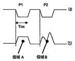
以上の二つの態様を図6(a)及び(b)に示す。これらの図は、パイロット噴射P1及びP2についての電圧放電分布及び対応する燃料送出量を示す。 The above two modes are shown in FIGS. 6 (a) and 6 (b). These figures show the voltage discharge distribution and corresponding fuel delivery for pilot injections P1 and P2.
以上の工程の結果、第2パイロット噴射P2中のバルブニードルの開放の持続時間は、単一の圧力振動についての期間とほぼ等しい。かくして、ノズル出口での燃料の圧力は、比較的高い圧力にまで上昇し、同じパイロット送出期間中は比較的低圧である。その結果、第2パイロット噴射送出分布(領域B)の下の面積は、第1パイロット噴射送出分布(領域A)の下の面積とほぼ等しい。換言すると、全送出容積には、噴射器ノズルの定在波セットアップ及びパイロット噴射分離の悪影響が実質的に及ぼされない。 As a result of the above steps, the duration of opening of the valve needle during the second pilot injection P2 is approximately equal to the period for a single pressure oscillation. Thus, the fuel pressure at the nozzle outlet rises to a relatively high pressure and is relatively low during the same pilot delivery period. As a result, the area under the second pilot injection delivery distribution (region B) is substantially equal to the area under the first pilot injection delivery distribution (region A). In other words, the total delivery volume is substantially unaffected by the injector nozzle standing wave setup and pilot injection separation.
上側の電圧放電波形は、「消勢噴射」噴射器に適用できる。しかしながら、本発明は、いわゆる「賦勢噴射」噴射器にも適用できるということは理解されるべきである。このような噴射器では、電圧放電パルスでなく、電圧充電パルスをアクチュエータに印加することによって噴射事象を開始する。 The upper voltage discharge waveform can be applied to a “de-energized” injector. However, it is to be understood that the present invention is also applicable to so-called “energized injection” injectors. In such injectors, an injection event is initiated by applying a voltage charge pulse to the actuator rather than a voltage discharge pulse.
換言すると「消勢噴射」の場合、電圧駆動分布の「作動電圧成分」は電圧放電パルスであり、「作動停止電圧成分」は電圧充電パルスである。「賦勢噴射」の場合には、電圧駆動分布の「作動電圧成分」は電圧充電パルスであり、「作動停止電圧成分」は電圧放電パルスである。 In other words, in the case of “extinguishing injection”, the “operation voltage component” of the voltage drive distribution is a voltage discharge pulse, and the “operation stop voltage component” is a voltage charge pulse. In the case of “energized injection”, the “operation voltage component” of the voltage drive distribution is a voltage charge pulse, and the “operation stop voltage component” is a voltage discharge pulse.
「噴射器オン時間」TONは、圧力波期間と等しくなるように選択される必要はないということは理解されるべきである。別の実施形態では、噴射器オン時間TONは、圧力波期間よりも大きくなるように選択してもよい。 It should be understood that the “injector on time” T ON need not be selected to be equal to the pressure wave period. In another embodiment, the injector on time T ON may be selected to be greater than the pressure wave time period.
本発明の効果は、図5に示す送出エラーを減少しようとすることであるということに着目されたい。換言すると、本発明の方法及び制御装置を作動すると、図5の繰り返し変化のピーク振幅が減少するのである。 It should be noted that the effect of the present invention is to reduce the transmission error shown in FIG. In other words, operating the method and controller of the present invention reduces the peak amplitude of the repetitive change of FIG.
圧力波期間は、燃料噴射システムの形状及び寸法を参照して計算してもよいし、別の態様では、試験装置で計測できる。いずれの場合でも、所与のエンジン作動パラメータについての圧力波期間は、適切には、制御装置20内の機能マップ30に記憶されていてもよい(図1参照)。変形例として、機能マップ30は、ECU又は車輛内のどこかのいずれかのデータ記憶装置32に記憶されていてもよい。
The pressure wave period may be calculated with reference to the shape and dimensions of the fuel injection system, or in another aspect can be measured with a test device. In any case, the pressure wave period for a given engine operating parameter may suitably be stored in a
上文中に説明した実施形態は、単なる例であって、本発明を限定しようとするものではなく、本発明の範囲は特許請求の範囲によって定義されるということは理解されよう。更に、上述の実施形態は、個々に使用してもよいし、組み合わせて使用してもよいということは理解されよう。 It will be understood that the embodiments described above are merely examples and are not intended to limit the invention, the scope of the invention being defined by the claims. Furthermore, it will be appreciated that the above-described embodiments may be used individually or in combination.
2 噴射器
4 アクチュエータ
6 バルブニードル
8 バルブニードル座
10 ノズル出口
20 噴射器制御ユニット(ICU)
22 エンジン制御ユニット(ECU)
24 エンジンパラメータ
25 電圧パルス分布
26 噴射器駆動回路
30 機能マップ
32 データ記憶装置
2 Injector 4 Actuator 6 Valve needle 8
22 Engine control unit (ECU)
24
Claims (13)
一つ又はそれ以上のエンジンパラメータに関するデータ(24)を受け入れるための入力部と、
前記アクチュエータ(4)を前記一つ又はそれ以上のエンジンパラメータ(24)に応じて制御するために、電圧駆動分布(25)を決定するためのプロセッサ(21)であって、前記電圧駆動分布は、噴射事象を開始する作動電圧成分と、噴射事象を終了する作動停止電圧成分とを含むように構成されており、前記作動電圧成分及び前記作動停止電圧成分は、時間間隔TONによって分離されている、プロセッサ(21)と、
前記プロセッサによって決定された前記電圧駆動分布(25)を前記アクチュエータに出力するための出力部とを備えており、
前記プロセッサ(21)は、時間間隔TONを、前記噴射器内の圧力波サイクルの所定の圧力波期間T P よりも大きいか或いは等しいように設定すべく構成される、制御装置。 A control apparatus for controlling the operation of one fuel injector (2) with a single piezoelectric actuator (4) (20), said actuator is operable by applying a voltage drive profile to the actuator In the control device,
An input for accepting data (24) relating to one or more engine parameters;
A processor (21) for determining a voltage drive distribution (25) to control the actuator (4) in response to the one or more engine parameters (24), the voltage drive distribution being The operation voltage component for starting the injection event and the operation stop voltage component for ending the injection event are included, and the operation voltage component and the operation stop voltage component are separated by a time interval T ON . A processor (21);
An output unit for outputting the voltage drive distribution (25) determined by the processor to the actuator;
It said processor (21), the time interval T ON, configured so as to set to be greater than or equal to a predetermined pressure wave time period T P of the pressure wave cycle within the injector, the control apparatus.
TON>TPである、制御装置。 The control device according to claim 1,
A T ON> T P, the control apparatus.
TON=nTPであり、ここで、n=1、2、3、・・・である、制御装置。 The control device according to claim 1 or 2,
A T ON = nT P, where, n = 1, 2, 3, a., Controller.
前記プロセッサは、前記噴射器(2)を通る燃料送出量を一定に維持するように、TONが変化する際の前記電圧パルス分布内のピーク電圧レベルを低下するように構成される、制御装置。 The control device according to claim 1, 2, or 3,
The processor is configured to maintain a fuel delivery rate through the injector (2) constant and to decrease the peak voltage level of the voltage pulse distribution when the T ON is changed, the controller .
前記一つ又はそれ以上のエンジンパラメータに応じて変化する所定の圧力波期間の値が、前記制御装置(20)に記憶される、制御装置。 In the control device according to any one of claims 1 to 4,
A control device, wherein a value of a predetermined pressure wave period that varies according to the one or more engine parameters is stored in the control device (20).
エンジンパラメータに応じて変化するTPの機能マップを備えており、前記制御装置は、TONを設定するとき、前記機能マップ(30)を参照するように構成される、制御装置。 The control device according to any one of claims 1 to 5, further comprising:
It has a function map of T P which varies according to the engine parameters, the control device, when setting the T ON, configured to refer to the function map (30), the control device.
前記機能マップ(30)を記憶するためのデータ記憶装置(32)を備える、制御装置。 The control device according to claim 6, further comprising:
A control device comprising a data storage device (32) for storing the function map (30).
所定の時間間隔T ON の経過後に、噴射事象を開始するように、前記アクチュエータに作動電圧(25)を印加する工程と、
噴射を終了するように、前記アクチュエータに作動停止電圧(25)を印加する工程とを含み、
前記所定の時間間隔T ON は、前記噴射器内の圧力波サイクルの所定の圧力波期間T P よりも大きいか或いは等しい、方法。 A method of operating a fuel injector (2) with a single piezoelectric actuator (4), wherein the piezoelectric actuator is to initiate an injection event by applying the operating voltage level to the actuator, operation stop voltage In a method operable to terminate an injection event by applying to the actuator;
Applying an actuation voltage (25) to the actuator to initiate an injection event after a predetermined time interval T ON has elapsed;
Applying a deactivation voltage (25) to the actuator to terminate injection,
It said predetermined time interval T ON is greater than or equal to a predetermined pressure wave time period T P of the pressure wave cycle within the injector, the method.
前記第1印加工程の前に、前記噴射器内の圧力波サイクルの前記圧力波期間を試験装置で計測する、方法。 The method of claim 9, wherein
The method of measuring the pressure wave period of the pressure wave cycle in the injector with a test device before the first application step.
前記第1印加工程の前に、前記噴射器内の圧力波サイクルの前記圧力波期間を、前記燃料噴射器及び関連した燃料噴射システムの寸法に基づいて計算する、方法。 The method of claim 9, wherein
Prior to the first application step, calculating the pressure wave duration of a pressure wave cycle in the injector based on dimensions of the fuel injector and associated fuel injection system.
前記圧力波期間は、所定範囲のエンジン作動条件について計測され、又は計算され、計測された又は計算された期間を機能マップ(30)に記憶する、方法。 12. The method according to claim 10 or 11,
The pressure wave period is measured or calculated for a predetermined range of engine operating conditions, and the measured or calculated period is stored in the function map (30).
Applications Claiming Priority (2)
| Application Number | Priority Date | Filing Date | Title |
|---|---|---|---|
| GB0610230A GB0610230D0 (en) | 2006-05-23 | 2006-05-23 | A method of operating a fuel injector |
| GB0621156A GB0621156D0 (en) | 2006-05-23 | 2006-10-24 | A method of operating a fuel injector |
Publications (3)
| Publication Number | Publication Date |
|---|---|
| JP2007315393A JP2007315393A (en) | 2007-12-06 |
| JP2007315393A5 JP2007315393A5 (en) | 2010-03-04 |
| JP4515487B2 true JP4515487B2 (en) | 2010-07-28 |
Family
ID=38440282
Family Applications (1)
| Application Number | Title | Priority Date | Filing Date |
|---|---|---|---|
| JP2007136349A Expired - Fee Related JP4515487B2 (en) | 2006-05-23 | 2007-05-23 | Control device for fuel injector and method for operating fuel injector |
Country Status (3)
| Country | Link |
|---|---|
| US (1) | US7681555B2 (en) |
| EP (1) | EP1860311B1 (en) |
| JP (1) | JP4515487B2 (en) |
Families Citing this family (5)
| Publication number | Priority date | Publication date | Assignee | Title |
|---|---|---|---|---|
| GB0614855D0 (en) * | 2006-07-26 | 2006-09-06 | Delphi Tech Inc | Method of operating a fuel injector |
| EP1956221B1 (en) * | 2007-02-02 | 2009-12-02 | Delphi Technologies, Inc. | A method of operating a piezoelectric actuator |
| DE102009018288B4 (en) * | 2009-04-21 | 2011-09-22 | Continental Automotive Gmbh | Method and device for determining a pressure in a high-pressure accumulator |
| US8161946B2 (en) * | 2009-11-20 | 2012-04-24 | Ford Global Technologies, Llc | Fuel injector interface and diagnostics |
| US11914408B2 (en) | 2022-01-21 | 2024-02-27 | Hamilton Sundstrand Corporation | Active flow control system |
Citations (4)
| Publication number | Priority date | Publication date | Assignee | Title |
|---|---|---|---|---|
| JPS61135980A (en) * | 1984-12-06 | 1986-06-23 | Diesel Kiki Co Ltd | Valve opening pressure detecting device and valve opening pressure control device for fuel injection valve |
| JPS61252846A (en) * | 1985-05-01 | 1986-11-10 | Nippon Soken Inc | Fuel injection valve controller having driving element which are energized electrically |
| JPH11159372A (en) * | 1997-11-25 | 1999-06-15 | Toyota Motor Corp | Injection control device for accumulator multiple cylinder engine |
| JP2006503533A (en) * | 2002-10-15 | 2006-01-26 | ローベルト ボツシユ ゲゼルシヤフト ミツト ベシユレンクテル ハフツング | Method and apparatus for controlling a piezo actuator |
Family Cites Families (18)
| Publication number | Priority date | Publication date | Assignee | Title |
|---|---|---|---|---|
| US4784102A (en) * | 1984-12-25 | 1988-11-15 | Nippon Soken, Inc. | Fuel injector and fuel injection system |
| JPS63243454A (en) * | 1987-03-12 | 1988-10-11 | ダイムラー―ベンツ・アクチェンゲゼルシャフト | Device for obtaining injection process in internal combustion engine, etc. |
| US5235954A (en) * | 1992-07-09 | 1993-08-17 | Anatoly Sverdlin | Integrated automated fuel system for internal combustion engines |
| JPH10213041A (en) * | 1997-01-31 | 1998-08-11 | Yamaha Motor Co Ltd | Liquid injector for internal combustion engine |
| EP1064457B1 (en) * | 1998-03-16 | 2002-06-12 | Siemens Aktiengesellschaft | Method for determining the injection time in a direct injection internal combustion engine |
| EP1081372B1 (en) * | 1999-08-31 | 2004-10-13 | Denso Corporation | Fuel injection device |
| US6364221B1 (en) * | 1999-09-29 | 2002-04-02 | Siemens Automotive Corporation | Electronic fuel injector actuated by magnetostrictive transduction |
| DE10061856A1 (en) * | 2000-12-12 | 2002-06-27 | Bosch Gmbh Robert | Method, computer program and control and / or regulating device for operating an internal combustion engine and internal combustion engine |
| US6792921B2 (en) * | 2001-12-17 | 2004-09-21 | Caterpillar Inc | Electronically-controlled fuel injector |
| JP4161635B2 (en) * | 2002-08-19 | 2008-10-08 | 株式会社デンソー | Fuel injection control device |
| DE10305525B4 (en) * | 2003-02-11 | 2014-04-24 | Robert Bosch Gmbh | Method and device for adapting the pressure wave correction in a high-pressure injection system of a motor vehicle while driving |
| JP4353781B2 (en) * | 2003-02-27 | 2009-10-28 | 株式会社日本自動車部品総合研究所 | Piezo actuator drive circuit |
| DE10311141B4 (en) * | 2003-03-14 | 2019-03-28 | Robert Bosch Gmbh | Method, computer program, storage medium and control and / or regulating device for operating an internal combustion engine, and internal combustion engine, in particular for a motor vehicle |
| ITBO20030642A1 (en) * | 2003-10-31 | 2005-05-01 | Magneti Marelli Powertrain Spa | METHOD FOR PILOTING AN INJECTOR WITH VERIFICATION |
| DE10355411B3 (en) * | 2003-11-27 | 2005-07-14 | Siemens Ag | Injection system and injection method for an internal combustion engine |
| DE102004053418B4 (en) * | 2004-03-24 | 2016-05-04 | Robert Bosch Gmbh | Method and device for pressure wave compensating control of temporally successive injections in an injection system of an internal combustion engine |
| DE102004037719A1 (en) * | 2004-08-04 | 2006-03-16 | Robert Bosch Gmbh | Fuel injection system controlling method for internal combustion engine, involves modulating control voltage that determines operation of piezoelectric actuator and is adjusted to pressure waves at nozzle needles in form of waves |
| US7140353B1 (en) * | 2005-06-28 | 2006-11-28 | Cummins Inc. | Fuel injector with piezoelectric actuator preload |
-
2007
- 2007-05-22 EP EP07252092A patent/EP1860311B1/en not_active Not-in-force
- 2007-05-22 US US11/805,494 patent/US7681555B2/en not_active Expired - Fee Related
- 2007-05-23 JP JP2007136349A patent/JP4515487B2/en not_active Expired - Fee Related
Patent Citations (4)
| Publication number | Priority date | Publication date | Assignee | Title |
|---|---|---|---|---|
| JPS61135980A (en) * | 1984-12-06 | 1986-06-23 | Diesel Kiki Co Ltd | Valve opening pressure detecting device and valve opening pressure control device for fuel injection valve |
| JPS61252846A (en) * | 1985-05-01 | 1986-11-10 | Nippon Soken Inc | Fuel injection valve controller having driving element which are energized electrically |
| JPH11159372A (en) * | 1997-11-25 | 1999-06-15 | Toyota Motor Corp | Injection control device for accumulator multiple cylinder engine |
| JP2006503533A (en) * | 2002-10-15 | 2006-01-26 | ローベルト ボツシユ ゲゼルシヤフト ミツト ベシユレンクテル ハフツング | Method and apparatus for controlling a piezo actuator |
Also Published As
| Publication number | Publication date |
|---|---|
| US20070273247A1 (en) | 2007-11-29 |
| JP2007315393A (en) | 2007-12-06 |
| EP1860311A3 (en) | 2008-08-27 |
| US7681555B2 (en) | 2010-03-23 |
| EP1860311B1 (en) | 2009-04-22 |
| EP1860311A2 (en) | 2007-11-28 |
Similar Documents
| Publication | Publication Date | Title |
|---|---|---|
| US7913666B2 (en) | Method and device for controlling an injection valve of an internal combustion engine | |
| JP5348154B2 (en) | Failure injection device for fuel injection system | |
| US8631785B2 (en) | Method for detecting deviations of injection quantities and for correcting the injection quantity, and injection system | |
| JP4515487B2 (en) | Control device for fuel injector and method for operating fuel injector | |
| JP4550862B2 (en) | Improvements in fuel injector control | |
| JP5796567B2 (en) | Fuel injection valve | |
| JP3867468B2 (en) | Common rail fuel injection system | |
| US8365704B2 (en) | Method and device for forming an electric control signal for an injection impulse | |
| JP5287915B2 (en) | Fuel injection state estimation device | |
| US9556814B2 (en) | Method for controlling pressure in a high-pressure region of an internal combustion engine | |
| JP5278472B2 (en) | Abnormality diagnosis device for fuel injection valve | |
| EP1860312B1 (en) | A Method of operating a fuel injector | |
| US7815128B2 (en) | Method and injection system for injecting a fluid | |
| JP2010101245A (en) | Fuel injection device | |
| WO2011078153A1 (en) | Device for determining abnormality in fuel injection valve, and method for determining abnormality in fuel injection valve | |
| US20090301431A1 (en) | Method of Controlling Common Rail Fuel Injection Device | |
| US20120166067A1 (en) | Method for controlling a fuel injector | |
| US20070169756A1 (en) | Controller and control method for an engine control unit | |
| JP2010007504A (en) | Fuel injection device | |
| KR101664626B1 (en) | Method and apparatus for controlling injector drive | |
| JP5392277B2 (en) | Fuel injection control device | |
| JP2020084851A (en) | Fuel injection control device of internal combustion engine | |
| JP5799895B2 (en) | Fuel injection control device | |
| JP2010084613A (en) | Fuel injection device | |
| JP2004124842A (en) | Fuel injection device for common rail system |
Legal Events
| Date | Code | Title | Description |
|---|---|---|---|
| A131 | Notification of reasons for refusal |
Free format text: JAPANESE INTERMEDIATE CODE: A131 Effective date: 20091014 |
|
| A524 | Written submission of copy of amendment under section 19 (pct) |
Free format text: JAPANESE INTERMEDIATE CODE: A524 Effective date: 20100114 |
|
| A521 | Written amendment |
Free format text: JAPANESE INTERMEDIATE CODE: A821 Effective date: 20100114 |
|
| TRDD | Decision of grant or rejection written | ||
| A01 | Written decision to grant a patent or to grant a registration (utility model) |
Free format text: JAPANESE INTERMEDIATE CODE: A01 Effective date: 20100413 |
|
| A01 | Written decision to grant a patent or to grant a registration (utility model) |
Free format text: JAPANESE INTERMEDIATE CODE: A01 |
|
| A61 | First payment of annual fees (during grant procedure) |
Free format text: JAPANESE INTERMEDIATE CODE: A61 Effective date: 20100512 |
|
| R150 | Certificate of patent or registration of utility model |
Free format text: JAPANESE INTERMEDIATE CODE: R150 |
|
| FPAY | Renewal fee payment (event date is renewal date of database) |
Free format text: PAYMENT UNTIL: 20130521 Year of fee payment: 3 |
|
| FPAY | Renewal fee payment (event date is renewal date of database) |
Free format text: PAYMENT UNTIL: 20130521 Year of fee payment: 3 |
|
| S111 | Request for change of ownership or part of ownership |
Free format text: JAPANESE INTERMEDIATE CODE: R313113 |
|
| FPAY | Renewal fee payment (event date is renewal date of database) |
Free format text: PAYMENT UNTIL: 20130521 Year of fee payment: 3 |
|
| R350 | Written notification of registration of transfer |
Free format text: JAPANESE INTERMEDIATE CODE: R350 |
|
| LAPS | Cancellation because of no payment of annual fees |