EP1064457B1 - Method for determining the injection time in a direct injection internal combustion engine - Google Patents
Method for determining the injection time in a direct injection internal combustion engine Download PDFInfo
- Publication number
- EP1064457B1 EP1064457B1 EP99913110A EP99913110A EP1064457B1 EP 1064457 B1 EP1064457 B1 EP 1064457B1 EP 99913110 A EP99913110 A EP 99913110A EP 99913110 A EP99913110 A EP 99913110A EP 1064457 B1 EP1064457 B1 EP 1064457B1
- Authority
- EP
- European Patent Office
- Prior art keywords
- injection
- pressure
- fuel
- combustion engine
- internal combustion
- Prior art date
- Legal status (The legal status is an assumption and is not a legal conclusion. Google has not performed a legal analysis and makes no representation as to the accuracy of the status listed.)
- Expired - Lifetime
Links
Images


Classifications
-
- F—MECHANICAL ENGINEERING; LIGHTING; HEATING; WEAPONS; BLASTING
- F02—COMBUSTION ENGINES; HOT-GAS OR COMBUSTION-PRODUCT ENGINE PLANTS
- F02D—CONTROLLING COMBUSTION ENGINES
- F02D41/00—Electrical control of supply of combustible mixture or its constituents
- F02D41/30—Controlling fuel injection
- F02D41/38—Controlling fuel injection of the high pressure type
- F02D41/3809—Common rail control systems
- F02D41/3836—Controlling the fuel pressure
-
- F—MECHANICAL ENGINEERING; LIGHTING; HEATING; WEAPONS; BLASTING
- F02—COMBUSTION ENGINES; HOT-GAS OR COMBUSTION-PRODUCT ENGINE PLANTS
- F02D—CONTROLLING COMBUSTION ENGINES
- F02D41/00—Electrical control of supply of combustible mixture or its constituents
- F02D41/30—Controlling fuel injection
- F02D41/38—Controlling fuel injection of the high pressure type
- F02D41/40—Controlling fuel injection of the high pressure type with means for controlling injection timing or duration
- F02D41/402—Multiple injections
- F02D41/403—Multiple injections with pilot injections
-
- F—MECHANICAL ENGINEERING; LIGHTING; HEATING; WEAPONS; BLASTING
- F02—COMBUSTION ENGINES; HOT-GAS OR COMBUSTION-PRODUCT ENGINE PLANTS
- F02B—INTERNAL-COMBUSTION PISTON ENGINES; COMBUSTION ENGINES IN GENERAL
- F02B3/00—Engines characterised by air compression and subsequent fuel addition
- F02B3/06—Engines characterised by air compression and subsequent fuel addition with compression ignition
-
- F—MECHANICAL ENGINEERING; LIGHTING; HEATING; WEAPONS; BLASTING
- F02—COMBUSTION ENGINES; HOT-GAS OR COMBUSTION-PRODUCT ENGINE PLANTS
- F02D—CONTROLLING COMBUSTION ENGINES
- F02D41/00—Electrical control of supply of combustible mixture or its constituents
- F02D41/24—Electrical control of supply of combustible mixture or its constituents characterised by the use of digital means
- F02D41/26—Electrical control of supply of combustible mixture or its constituents characterised by the use of digital means using computer, e.g. microprocessor
- F02D41/28—Interface circuits
- F02D2041/286—Interface circuits comprising means for signal processing
- F02D2041/288—Interface circuits comprising means for signal processing for performing a transformation into the frequency domain, e.g. Fourier transformation
-
- F—MECHANICAL ENGINEERING; LIGHTING; HEATING; WEAPONS; BLASTING
- F02—COMBUSTION ENGINES; HOT-GAS OR COMBUSTION-PRODUCT ENGINE PLANTS
- F02D—CONTROLLING COMBUSTION ENGINES
- F02D41/00—Electrical control of supply of combustible mixture or its constituents
- F02D41/30—Controlling fuel injection
- F02D41/38—Controlling fuel injection of the high pressure type
- F02D2041/389—Controlling fuel injection of the high pressure type for injecting directly into the cylinder
-
- F—MECHANICAL ENGINEERING; LIGHTING; HEATING; WEAPONS; BLASTING
- F02—COMBUSTION ENGINES; HOT-GAS OR COMBUSTION-PRODUCT ENGINE PLANTS
- F02D—CONTROLLING COMBUSTION ENGINES
- F02D2200/00—Input parameters for engine control
- F02D2200/02—Input parameters for engine control the parameters being related to the engine
- F02D2200/06—Fuel or fuel supply system parameters
- F02D2200/0602—Fuel pressure
-
- F—MECHANICAL ENGINEERING; LIGHTING; HEATING; WEAPONS; BLASTING
- F02—COMBUSTION ENGINES; HOT-GAS OR COMBUSTION-PRODUCT ENGINE PLANTS
- F02D—CONTROLLING COMBUSTION ENGINES
- F02D2200/00—Input parameters for engine control
- F02D2200/02—Input parameters for engine control the parameters being related to the engine
- F02D2200/06—Fuel or fuel supply system parameters
- F02D2200/0614—Actual fuel mass or fuel injection amount
-
- F—MECHANICAL ENGINEERING; LIGHTING; HEATING; WEAPONS; BLASTING
- F02—COMBUSTION ENGINES; HOT-GAS OR COMBUSTION-PRODUCT ENGINE PLANTS
- F02D—CONTROLLING COMBUSTION ENGINES
- F02D2250/00—Engine control related to specific problems or objectives
- F02D2250/04—Fuel pressure pulsation in common rails
-
- F—MECHANICAL ENGINEERING; LIGHTING; HEATING; WEAPONS; BLASTING
- F02—COMBUSTION ENGINES; HOT-GAS OR COMBUSTION-PRODUCT ENGINE PLANTS
- F02D—CONTROLLING COMBUSTION ENGINES
- F02D2250/00—Engine control related to specific problems or objectives
- F02D2250/31—Control of the fuel pressure
-
- F—MECHANICAL ENGINEERING; LIGHTING; HEATING; WEAPONS; BLASTING
- F02—COMBUSTION ENGINES; HOT-GAS OR COMBUSTION-PRODUCT ENGINE PLANTS
- F02D—CONTROLLING COMBUSTION ENGINES
- F02D41/00—Electrical control of supply of combustible mixture or its constituents
- F02D41/30—Controlling fuel injection
- F02D41/38—Controlling fuel injection of the high pressure type
- F02D41/40—Controlling fuel injection of the high pressure type with means for controlling injection timing or duration
- F02D41/402—Multiple injections
-
- Y—GENERAL TAGGING OF NEW TECHNOLOGICAL DEVELOPMENTS; GENERAL TAGGING OF CROSS-SECTIONAL TECHNOLOGIES SPANNING OVER SEVERAL SECTIONS OF THE IPC; TECHNICAL SUBJECTS COVERED BY FORMER USPC CROSS-REFERENCE ART COLLECTIONS [XRACs] AND DIGESTS
- Y02—TECHNOLOGIES OR APPLICATIONS FOR MITIGATION OR ADAPTATION AGAINST CLIMATE CHANGE
- Y02T—CLIMATE CHANGE MITIGATION TECHNOLOGIES RELATED TO TRANSPORTATION
- Y02T10/00—Road transport of goods or passengers
- Y02T10/10—Internal combustion engine [ICE] based vehicles
- Y02T10/40—Engine management systems
Definitions
- the invention relates to a method for determining the injection time in a direct injection internal combustion engine according to the preamble of claim 1.
- Diesel direct injection is one Control.
- the combustion process with regard to exhaust gas emissions and to optimize the combustion noise, it is known, the injection process in one or more pilot injections and in one or more main injections divide.
- the required amount of injection into the cylinders required control time of the injectors is determined by a map determined.
- An important input variable for the map is the current pressure in the supply line or in Pressure accumulator, often as a common rail or simply as a rail referred to, since this is measured.
- the pressure in the supply is assumed to be constant in known systems. That the control time becomes the same pressure of the injectors for the pre and the main injection determined.
- the pressure between two consecutive injections e.g. between pre and main injection but can only be regarded as constant in rough approximation, as measurements prove.
- the invention has for its object a method for Determining the injection time in an internal combustion engine Specify initially mentioned type, so that in a division of the injection process into several injections The amount of fuel corresponds as closely as possible to the target value.
- the pressure fluctuations that occur during two consecutive Injections (e.g. pre and main injection) within the same working cycle of a cylinder in the supply line to the injector are taken into account with a correction term and with the corrected pressure the activation time of the Injectors determined so that the desired amount of fuel is injected.
- the correction term is determined using a Least squares estimator, which depends on the geometric data of the system, especially the length of the Supply from the rail to the injector and the physical Boundary conditions, e.g. the fuel temperature the injection pressure at the injector nozzle.
- Figure 1 shows schematically the structure of a fuel injection system for a direct injection internal combustion engine, as they are called common rail system above all used in vehicles with a diesel internal combustion engine becomes.
- the control unit 19 is preferably in one integrated electronic control unit 28 of the internal combustion engine, all of which are necessary to operate the internal combustion engine Controls and / or regulates processes.
- the control unit 28 of the internal combustion engine by means of a corresponding Sensor input signals ES supplied.
- the individual actuators and components are output signals AS controlled that to operate the internal combustion engine are necessary.
- Pressure control valve 16 controls and / or regulates one Fuel line 25 excess fuel that is not used Maintaining a desired one in the high pressure accumulator 17 Pressure is required in the fuel tank 10, wherein the holding pressure of the pressure control valve 16 from the control unit 19 is set via a control line 24.
- Pressure control in the high-pressure accumulator 17 is also a pressure sensor 23 provided. This pressure sensor 23 is used for detection of the one currently prevailing in the high-pressure accumulator 17 Pressure p, on the basis of which the control unit 19 accordingly the desired operating conditions of the internal combustion engine performs the pressure control via the pressure control valve 16.
- Fuel pressures from 0 to 1500 generate bar are available via fuel injection lines 27 on injectors or injection valves 18 (only one shown) in the combustion chambers of the internal combustion engine (not shown) are arranged. These injectors 18 generally have an injector which are closed with a spring-loaded needle is. The injection process is done by the control unit 19 triggered via control lines 26 with the injection valves 18 is connected. The one in the injectors 18 leakage current continues to occur via fuel lines 21 returned to the fuel tank 10.
- FIG. 2 shows the time course of the control signal U shown for an injector.
- the injector controlled to trigger a pre-injection.
- To a time interval at a given speed in this example corresponds to 60 ° crank angle KW, takes place at Time t2 the main injection.
- FIG. 3 The result of such a control of the injector pressure course over time is shown in FIG. 3.
- the Opening the injector nozzle triggers a pressure fluctuation, that at the time of the start of the main injection has not subsided.
- the starting pressure at the beginning of the main injection is different to the pressure at the start of the pre-injection.
- the starting pressure for the main injection can be higher or be lower and also changes in the form of a muted Vibration constantly its value.
- the short-time FFT is used for transient signals, analyze the frequency response over time. This will the measured data set in sections where the signal can be regarded as stationary, divided and these then individually transformed into the frequency domain using an FFT.
- Short-time FFT cannot start the oscillation be determined because the frequency resolution is too low.
- a One possibility is to use the cross correlation function. A vibration limited in time to a period the frequency sought is correlated with the measurement data set. The resulting relative extremum corresponds then the start of the vibration.
- the frequency f is derived from the frequency analysis using the FFT received and the start time of the vibration with the Cross correlation function obtained.
- the amplitude A, the Attenuation d and phase ⁇ are used for the signal model, namely with the least squares estimator described later certainly.
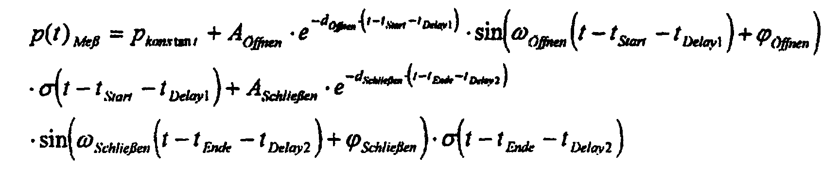
- p (t) measuring p cons tan t + p ( t ) To open + p ( t ) Conclude . wherein p cons tan t to the pressure sensor 23 is determined (Fig. 1).
- the least squares estimator is a linear estimator, i.e. the frequencies of the vibrations must be from a time-frequency analysis be won.
- Attenuation d can be corrected using a constant during design or estimated using a power series approach.
- e -dt 1- dt 1! + ( dt ) 2 2! - ( dt ) 3 3! + ...
- the least squares estimator provides phase and damping.
- the estimator is set up here as an example for a frequency for a damped oscillation that occurs.
- This estimated pressure curve p (t) is shown graphically in FIG. 4b.
- the pressure curve actually occurring in the feed line (fuel injection line 27 in FIG. 1) to the injector is shown in FIG. 4a.
- the absolute error is plotted in FIG. 4c as the difference between the measured pressure curve (FIG. 4a) and the estimated pressure curve (FIG. 4b).
- the pressure can be determined using the specified Procedures can be estimated. Since the time of Start of the subsequent injection process (e.g. main injection) can be freely chosen and is known, the pressure value present at the time of the injection time calculation considered for this injection process become. This can be done, for example, in that Input variable for a in a memory 29 of the control unit 19 stored map KF, in which depending on the current Value for the rail pressure and the required fuel injection quantity Injection times are stored, not the measured one Pressure in the rail, but one around the estimated pressure value corrected pressure value is used at the start of injection. This enables the required amount of fuel to be measured with high accuracy be measured.
Description
Die Erfindung betrifft ein Verfahren zum Bestimmen der Einspritzzeit bei einer direkteinspritzenden Brennkraftmaschine gemäß dem Oberbegriff des Patentanspruches 1.The invention relates to a method for determining the injection time in a direct injection internal combustion engine according to the preamble of claim 1.
Bei der Diesel-Direkt-Einspritzung handelt es sich um eine Steuerung. Um den Verbrennungsverlauf hinsichtlich der Abgasemission und des Vebrennungsgeräusches zu optimieren, ist es bekannt, den Einspritzvorgang in eine oder mehrere Voreinspritzungen und in einen oder mehrere Haupteinspritzungen aufzuteilen. Die für die gewünschte Einspritzmenge in die Zylinder erforderliche Ansteuerzeit der Injektoren wird mittels eines Kennfelds ermittelt. Eine wichtige Eingangsgröße für das Kennfeld ist der momentane Druck in der Zuleitung bzw. im Druckspeicher, vielfach als Common Rail oder einfach als Rail bezeichnet, da dieser meßtechnisch erfaßt wird. Der Druck in der Zuleitung wird bei bekannten Systemen als konstant vorausgesetzt. D.h. es wird mit demselben Druck die Ansteuerzeit der Injektoren für die Vor- als auch die Haupteinspritzung ermittelt. Der Druck zwischen zwei aufeinanderfolgenden Einspritzungen, z.B. zwischen Vor- und Haupteinspritzung kann jedoch nur in grober Näherung als konstant angesehen werden, wie Messungen belegen. Es ergeben sich Druckschwankungen im Injektor und in der Zuleitung, die zu einer merklichen Änderung der Einspritzmenge führen.Diesel direct injection is one Control. The combustion process with regard to exhaust gas emissions and to optimize the combustion noise, it is known, the injection process in one or more pilot injections and in one or more main injections divide. The required amount of injection into the cylinders required control time of the injectors is determined by a map determined. An important input variable for the map is the current pressure in the supply line or in Pressure accumulator, often as a common rail or simply as a rail referred to, since this is measured. The pressure in the supply is assumed to be constant in known systems. That the control time becomes the same pressure of the injectors for the pre and the main injection determined. The pressure between two consecutive injections, e.g. between pre and main injection but can only be regarded as constant in rough approximation, as measurements prove. There are pressure fluctuations in the Injector and in the supply line leading to a noticeable change of the injection quantity.
Der Erfindung liegt die Aufgabe zugrunde, ein Verfahren zum Bestimmen der Einspritzzeit bei einer Brennkraftmaschine der Eingangs genannnten Art anzugeben, so daß bei einer Aufteilung des Einspritzvorganges in mehrere Einspritzungen die zuzuführende Kraftstoffmenge möglichst genau dem Sollwert entspricht.The invention has for its object a method for Determining the injection time in an internal combustion engine Specify initially mentioned type, so that in a division of the injection process into several injections The amount of fuel corresponds as closely as possible to the target value.
Diese Aufgabe wird durch die Merkmale des Patentanspruches 1 gelöst. Vorteilhafte Weiterbildungen sind in den Unteransprüchen angegeben.This object is achieved by the features of claim 1 solved. Advantageous further developments are in the subclaims specified.
Die auftretenden Druckschwankungen während zwei aufeinanderfolgenden Einspritzungen (z.B. Vor-und Haupteinspritzung) innerhalb desselben Arbeitsspieles eines Zylinders in der Zuleitung zum Injektor werden mit einem Korrekturterm berücksichtigt und mit dem korrigierten Druck die Ansteuerzeit der Injektoren ermittelt, so daß die gewünschte Kraftstoffmenge eingespritzt wird. Der Korrekturterm wird mit Hilfe eines Least-Squares-Schätzers bestimmt, der in Abhängigkeit der geometrischen Daten des Systems, insbesondere der Länge der Zuleitung vom Rail zu dem Injektor und der physikalischen Randbedingungen, z.B. der Kraftstofftemperatur den Einspritzdruck an der Düse des Injektors schätzt.The pressure fluctuations that occur during two consecutive Injections (e.g. pre and main injection) within the same working cycle of a cylinder in the supply line to the injector are taken into account with a correction term and with the corrected pressure the activation time of the Injectors determined so that the desired amount of fuel is injected. The correction term is determined using a Least squares estimator, which depends on the geometric data of the system, especially the length of the Supply from the rail to the injector and the physical Boundary conditions, e.g. the fuel temperature the injection pressure at the injector nozzle.
Die Erfindung wird anhand der Figuren näher erläutert. Es zeigen
- Figur 1
- eine schematische Darstellung eines Einspritzsystems für eine direkteinspritzende Brennkraftmaschine,
- Figur 2
- den Verlauf der Ansteuerspannung für den Injektor,
- Figur 3
- den Druckverlauf in der Zuleitung bei einer Vor-und einer Haupteinspritzung,
- Figur 4
- einen Vergleich zwischen gemessenem Druckverlauf, geschätztem Druckverlauf und den daraus berechneten Fehler des Schätzers
- Figure 1
- 1 shows a schematic representation of an injection system for a direct-injection internal combustion engine,
- Figure 2
- the course of the control voltage for the injector,
- Figure 3
- the pressure curve in the supply line for a pre-injection and a main injection,
- Figure 4
- a comparison between the measured pressure curve, the estimated pressure curve and the error of the estimator calculated therefrom
Die Figur 1 zeigt schematisch den Aufbau eines Kraftstoffeinspritzsystems für eine direkteinspritzende Brennkraftmaschine, wie sie unter der Bezeichnung Common-Rail-System vor allem bei Fahrzeugen mit einer Diesel-Brennkraftmaschine eingesetzt wird.Figure 1 shows schematically the structure of a fuel injection system for a direct injection internal combustion engine, as they are called common rail system above all used in vehicles with a diesel internal combustion engine becomes.
Bei diesem Einspritzsystem wird Kraftstoff aus einem Kraftstoffvorratsbehälter
10 über eine Kraftstoffleitung 11 durch
eine Vorförderpumpe 12 angesaugt. Die Vorförderpumpe 12 fördert
den Kraftstoff über einen Kraftstoffilter 13 zu einer
Hochdruckpumpe 15, die den Kraftstoff verdichtet und unter
hohem Druck in einen Hochdruckspeicher 17 einspeist.With this injection system, fuel is generated from a
Um den Volumenstrom der Hochdruckpumpe 15 in den Hochdruckspeicher
17 entsprechend den jeweiligen Betriebsbedingungen
der Brennkraftmaschine bedarfsabhängig einstellen zu können,
ist in der Kraftstoffleitung 11 zwischen der Vorförderpumpe
12 und der Hochdruckpumpe 15 ein zusätzliches Saugdrosselventil
14 angeordnet, mit dessen Hilfe der Förderstrom der Hochdruckpumpe
15 geregelt werden kann. Dieses Saugdrosselventil
14 wird von einer Steuereinheit 19 über eine Steuerleitung 22
angesteuert. Die Steuereinheit 19 ist vorzugsweise in ein
elektronisches Steuergerät 28 der Brennkraftmaschine integriert,
das alle zum Betrieb der Brennkraftmaschine nötigen
Abläufe steuert und/oder regelt. Hierzu werden dem Steuergerät
28 der Brennkraftmaschine eine Vielzahl mittels entsprechender
Sensorik aufgenommene Eingangssignale ES zugeführt.
Über Ausgangssignale AS werden die einzelnen Aktoren und Komponenten
angesteuert, die zum Betrieb der Brennkraftmaschine
notwendig sind.To the volume flow of the
Um den Druck im Hochdruckspeicher 17 entsprechend den gewünschten
Betriebsbedingungen der Brennkraftmaschine einstellen
zu können, ist weiterhin nach der Hochdruckpumpe 15 ein
Druckregelventil 16 in die Kraftstoffleitung 11 geschaltet.
Dieses Druckregelventil 16 steuert und/ oder regelt über eine
Kraftstoffleitung 25 überschüssigen Kraftstoff, der nicht zur
Aufrechterhaltung eines im Hochdruckspeicher 17 gewünschten
Drucks benötigt wird, in den Kraftstoffvorratsbehälter 10 ab,
wobei der Haltedruck des Druckregelventils 16 von der Steuereinheit
19 über eine Steuerleitung 24 eingestellt wird. Zur
Druckregelung im Hochdruckspeicher 17 ist weiter ein Drucksensor
23 vorgesehen. Dieser Drucksensor 23 dient zum Erfassen
des augenblicklich im Hochdruckspeicher 17 herrschenden
Druckes p, auf dessen Grundlage die Steuereinheit 19 entsprechend
den gewünschten Betriebsbedingungen der Brennkraftmaschine
die Druckregelung über das Druckregelventil 16 vornimmt.To the pressure in the
Im Hochdruckspeicher 17 lassen sich mit Hilfe der dargestellten
Druckregeleinrichtungen Kraftstoffdrücke von 0 bis 1500
bar erzeugen. Diese Kraftstoffdrücke stehen über Kraftstoffeinspritzleitungen
27 an Injektoren oder Einspritzventilen 18
(nur eines gezeigt), die in den Brennkammern der Brennkraftmaschine
(nicht gezeigt) angeordnet sind, an. Diese Einspritzventile
18 weisen im allgemeinen eine Einspritzdüse
auf, die mit einer unter Federkraft stehenden Nadel verschlossen
ist. Der Einspritzvorgang wird durch die Steuereinheit
19 ausgelöst, die über Steuerleitungen 26 mit den Einspritzventilen
18 verbunden ist. Der in den Einspritzventilen
18 weiterhin auftretende Leckagestrom wird über Kraftstoffleitungen
21 in den Kraftstoffvorratsbehälter 10 zurückgeführt.In the high-
In Figur 2 ist der zeitliche Verlauf des Ansteuersignals U für einen Injektor dargestellt. Zum Zeitpunkt t1 wird der Injektor zur Auslösung einer Voreinspritzung angesteuert. Nach einem zeitlichen Abstand, der bei einer vorgegebenen Drehzahl in diesem Bespiel 60°Kurbelwinkel KW entspricht, erfolgt um Zeitpunkt t2 die Haupteinspritzung.FIG. 2 shows the time course of the control signal U shown for an injector. At time t1 the injector controlled to trigger a pre-injection. To a time interval at a given speed in this example corresponds to 60 ° crank angle KW, takes place at Time t2 the main injection.
Der sich aufgrund einer solchen Ansteuerung des Injektors ergebende zeitliche Druckverlauf ist in Figur 3 gezeigt. Das Öffnen der Düse des Injektors löst eine Druckschwankung aus, die zum Zeitpunkt des Beginns der Haupteinspritzung noch nicht abgeklungen ist. Wie aus dieser Darstellung ersichtlich ist, ist der Startdruck zu Beginn der Haupteinspritzung unterschiedlich zu dem Druck bei Beginn der Voreinspritzung. In Abhängigkeit von dem Abstand zwischen den beiden Einspritzungen kann der Startdruck für die Haupteinspritzung höher oder niedriger sein und ändert zudem in Form einer gedämpften Schwingung ständig seinen Wert.The result of such a control of the injector pressure course over time is shown in FIG. 3. The Opening the injector nozzle triggers a pressure fluctuation, that at the time of the start of the main injection has not subsided. As can be seen from this illustration the starting pressure at the beginning of the main injection is different to the pressure at the start of the pre-injection. In Depends on the distance between the two injections the starting pressure for the main injection can be higher or be lower and also changes in the form of a muted Vibration constantly its value.
Mit Hilfe der aus der Signalverarbeitung bekannten Short-Time FFT (Fast Fourier Transformation) werden die typischen Frequenzen und die Amplitude der Schwingungen ermittelt, die durch den Einspritzvorgang ausgelöst werden.With the help of the short time known from signal processing FFT (Fast Fourier Transformation) are the typical frequencies and determined the amplitude of the vibrations that are triggered by the injection process.
Die Short-Time-FFT dient dazu, bei instationären Signalen, den Frequenzverlauf über der Zeit zu analysieren. Dazu wird der gemessene Datensatz in Abschnitte, in denen das Signal als stationär angesehen werden kann, unterteilt und diese dann einzeln mittels einer FFT in den Frequenzbereich transformiert.The short-time FFT is used for transient signals, analyze the frequency response over time. This will the measured data set in sections where the signal can be regarded as stationary, divided and these then individually transformed into the frequency domain using an FFT.
Der Beginn der Schwingung kann nicht mittels Short-Time-FFT bestimmt werden, da die Frequenzauflösung zu gering wird. Eine Möglichkeit ist die Verwendung der Kreuzkorrelationsfunktion. Eine auf eine Periode zeitlich beschränkte Schwingung der gesuchten Frequenz wird hierbei mit dem Meßdatensatz korreliert. Das sich dabei ergebende relative Extremum entspricht dann dem zeitlichen Beginn der Schwingung.Short-time FFT cannot start the oscillation be determined because the frequency resolution is too low. A One possibility is to use the cross correlation function. A vibration limited in time to a period the frequency sought is correlated with the measurement data set. The resulting relative extremum corresponds then the start of the vibration.
Die durch den Einspritzvorgang ausgelösten Druckschwankungen
können mit dem Signalansatz für eine gedämpfte Schwingung beschrieben
werden. Es gilt allgemein:

- A
- Amplitude
- d
- Dämpfungsfaktor
- t0
- Startzeitpunkt der Schwingung
- f
- Frequenz
- ϕ
- Phase
- σ(t - t 0)
- Sprungfunktion zum Zeitpunkt t0=0
- A
- amplitude
- d
- damping factor
- t 0
- Start time of the vibration
- f
- frequency
- φ
- phase
- σ ( t - t 0 )
- Jump function at time t 0 = 0
Die Frequenz f wird aus der Frequenzanalyse mittels der FFT erhalten und der Startzeitpunkt der Schwingung mit der Kreuzkorrelationsfunktion gewonnen. Die Amplitude A, die Dämpfung d und die Phase ϕ werden für das Signalmodell, nämlich mit dem später näher beschriebenen Least-Squares-Schätzer bestimmt.The frequency f is derived from the frequency analysis using the FFT received and the start time of the vibration with the Cross correlation function obtained. The amplitude A, the Attenuation d and phase ϕ are used for the signal model, namely with the least squares estimator described later certainly.
Die Kraftstoffmasse in der Zuleitung des Injektors wird vor
dem Beginn der Voreinspritzung als ruhend angenommen. Durch
das Öffnen der Düsennadel des Injektors breitet sich ausgehend
vom Sackloch eine Druckwelle aus. Diese Verdünnungswelle
bewegt sich durch den Injektor, in die Zuleitung und schließlich
in das Rail. Aufgrund des Druckabfalls am Sackloch setzt
sich die Kraftstoffmasse in Bewegung. Kraftstoffteilchen die
nahe am Sackloch liegen, setzen sich in Bewegung, der Kraftstoff
entspannt sich. Das heißt die Verdünnungswelle löst eine
Verdichtungswelle mit entgegengesetzter Ausbreitungsrichtung
aus. Dadurch wird der Druck im Sackloch wieder erhöht.
Durch diese Bewegung entsteht eine gedämpfte Schwingung des
Druckes im Sackloch. Diese Schwingung kann ausgehend von der
oben allgemein angegebenen Gleichung angegeben werden zu:

- Aöffnen
- Amplitude der Öffnungswelle
- dÖffnen
- Dämpfung der Öffnungswelle
- ϕÖffnen
- Phase der Öffnungswelle
- ωÖffnen
- Frequenz der Öffnungswelle
- tStart
- Start der Ansteuerung
- tDelay1
- Verzugszeit bis zum öffnen der Nadel
- t0
- = tDelay1 - tStart
- Open A
- Amplitude of the opening wave
- d Open
- Damping the opening shaft
- ϕ Open
- Phase of the opening wave
- ω open
- Frequency of the opening wave
- t start
- Start of control
- t Delay1
- Delay time until the needle opens
- t 0
- = t Delay1 - t start
Durch das Schließen der Düsennadel wird die Kraftstoffmenge
im Sackloch ruckartig abgebremst. Es läuft eine Verdichtungswelle
durch den Injektor in die Leitung und ins Rail (vgl.
oben).
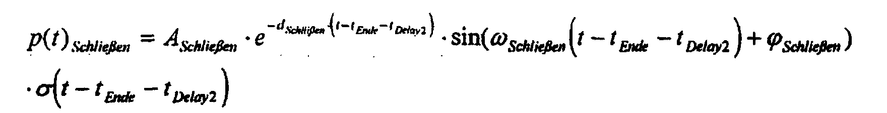
- ASchließen
- Amplitude der Schließwelle
- dSchließen
- Dämpfung der Schließwelle
- ϕSchließen n
- Phase der Schließwelle
- ωSchließen
- Frequenz der Schließwelle
- tEnde
- Ende der Ansteuerung
- tDelay2
- Verzugszeit bis zum Schließen der Nadel
- A close
- Amplitude of the closing shaft
- d Close
- Damping the closing shaft
- ϕ Close n
- Phase of the closing shaft
- ω close
- Frequency of the closing wave
- t end
- End of control
- t Delay2
- Delay time until the needle closes
Bezeichnet man mit p(t) Meß den Druckverlauf, wie er sich aufgrund
des öffnens und Schließens der Düsennadel, sowie des
konstanten Raildruckes pkons tan t einstellt, so gilt:
Werden in diese Gleichung die oben angegebenen Terme eingesetzt,
so ergibt sich
Der Least-Squares-Schätzer ist ein linearer Schätzer, d.h. die Frequenzen der Schwingungen müssen aus einer Zeit-Frequenz-Analyse gewonnen werden.The least squares estimator is a linear estimator, i.e. the frequencies of the vibrations must be from a time-frequency analysis be won.
Die Dämpfung d kann mittels einer Konstanten während des Entwurfs
korrigiert werden oder mittels eines Potenzreihenansatzes
geschätzt werden.
Eine weitere Möglichkeit zur besseren Bestimmung der Amplitude, Phase und der Dämpfung bietet der Least-Squares-Schätzer.Another way to better determine the amplitude, The least squares estimator provides phase and damping.
Der Schätzer wird hier exemplarisch für eine Frequenz für eine
auftretende gedämpfte Schwingung aufgestellt.


Allgemein gilt für einen linearen Least-Square-Schätzer:

![]()
![]()
![]()
![]()
Für den Schätzer folgt nun:
Diese Inverse existieren immer, wenn die Basis b1,b2 linear unabhängig ist.These inverses always exist when the bases b1, b2 are linear is independent.
Das Symbol "Λ" über dem jeweiligen Parameter bedeutet, daß es sich um Schätzwerte handelt.The symbol "Λ" above the respective parameter means that they are estimates.
Es ergeben sich dann:
Daraus folgt für die Phase die Beziehung
Das geschätzte Signal, d.h. der geschätzte Druckverlauf ergibt
sich dann zu:

In Figur 4b ist dieser geschätzte Druckverlauf p(t) graphisch
dargestellt. Der in der Zuleitung (Kraftstoffeinspritzleitung
27 in Figur 1) zum Injektor tatsächlich auftretende
Druckverlauf ist in Figur 4a dargestellt. Zum Zeitpunkt t1
(=tStart) wird die Voreinspritzung ausgelöst. Bis zu diesem
Zeitpunkt wird die Kraftstoffmasse als ruhend angenommen
(konstanter Wert des Druckes 780 bar). In Figur 4c ist der
absolute Fehler als Differenz zwischen gemessenem Druckverlauf
(Figur 4a) und geschätztem Druckverlauf (Figur 4b) aufgetragen.This estimated pressure curve p (t) is shown graphically in FIG. 4b. The pressure curve actually occurring in the feed line (
Zu jedem beliebigen Zeitpunkt nach erfolgtem Einspritzvorgang
(z.B. Voreinspritzung) kann also der Druck mittels dem angegebenen
Verfahren abgeschätzt werden. Da der Zeitpunkt des
Beginns des nachfolgenden Einspritzvorganges (z.B. Haupteinspritzung)
frei gewählt werden kann und bekannt ist, kann der
zu diesem Zeitpunkt vorliegende Druckwert bei der Einspritzzeitberechnung
für diesen Einspritzvorgang berücksichtigt
werden. Dies kann beispielsweise dadurch geschehen, daß als
Eingangsgröße für ein in einem Speicher 29 der Steuereinheit
19 abgelegtes Kennfeld KF, in dem abhängig vom momentanen
Wert für den Raildruck und der geforderten Kraftstoffeinspritzmenge
Einspritzzeiten abgelegt sind, nicht der gemessene
Druck im Rail, sondern ein um den geschätzten Druckwert
zum Einspritzbeginn korrigierter Druckwert verwendet wird.
Damit kann die geforderte Kraftstoffmenge mit hoher Genauigkeit
zugemessen werden.At any time after the injection process
(e.g. pre-injection), the pressure can be determined using the specified
Procedures can be estimated. Since the time of
Start of the subsequent injection process (e.g. main injection)
can be freely chosen and is known, the
pressure value present at the time of the injection time calculation
considered for this injection process
become. This can be done, for example, in that
Input variable for a in a
Claims (8)
- Method for determining the injection time in a direct-injection internal combustion engine having a high-pressure reservoir (17) which contains fuel and is connected to an injector (18) so that fuel can be injected under control into the cylinder of the internal combustion engine as a function of at least the pressure in the high-pressure reservoir (17) and the required fuel quantity,the calculated total quantity of fuel which is to be fed to a cylinder of the internal combustion engine being split up into at least two injection processes per cylinder stroke, andthe pressure fluctuations in the injector (18), which occur between two individual injection processes (n, n+1), and in the line (27) between the high-pressure reservoir (17) and injector (18) are taken into account when determining the injection time for the next injection process (n+1).
- Method according to Claim 1, characterized in that the total quantity of fuel is dosed by means of a pre-injection (n) and a main injection (n+1), and the pressure fluctuations initiated by the pre-injection are taken into account when determining the injection time for the main injection.
- Method according to Claim 1, characterized in that the total quantity of fuel is dosed by means of a plurality of pre-injections (n, n+1, n+i) and one main injection (n+i+1) and the pressure fluctuations initiated by the respective pre-injections are taken into account when determining the injection time for the respectively following pre-injection or the following main injection.
- Method according to one of Claims 1-3, characterized in that the pressure fluctuations occurring between the individual injection processes (n,n+1) are used in each case to determine a correction term with the aid of which the pressure in the high-pressure reservoir (17) is corrected, and the injection time is determined with the aid of the corrected pressure value.
- Method according to Claim 4, characterized in that the corrected pressure value is an input variable of a characteristic diagram (KF) in which the injection times are stored as a function of the required fuel quantity.
- Method according to Claim 1, characterized in that the correction term is determined with the aid of a least-squares estimator which, on the basis of the equation of the damped oscillation for the pressure fluctuations determines the injection pressure at the nozzle of the injector (17) as a function of the geometrical data of the injection system and of the physical boundary conditions.
- Method according to Claim 6, characterized in that it holds for the estimation equation for the pressure fluctuations thatwhere

- A
- is the amplitude of the oscillation
- d
- is the damping factor
- t0
- is the starting instant of the oscillation
- f
- is the frequency
- ϕ
- is the phase, and
- σ(t-t 0)
- is the jump function at the instant t=0.
- Method according to Claim 7, characterized in that the following equation holds for the estimated pressure characteristic:

Applications Claiming Priority (3)
| Application Number | Priority Date | Filing Date | Title |
|---|---|---|---|
| DE19811359 | 1998-03-16 | ||
| DE19811359 | 1998-03-16 | ||
| PCT/DE1999/000652 WO1999047802A1 (en) | 1998-03-16 | 1999-03-10 | Method for determining the injection time in a direct injection internal combustion engine |
Publications (2)
| Publication Number | Publication Date |
|---|---|
| EP1064457A1 EP1064457A1 (en) | 2001-01-03 |
| EP1064457B1 true EP1064457B1 (en) | 2002-06-12 |
Family
ID=7861064
Family Applications (1)
| Application Number | Title | Priority Date | Filing Date |
|---|---|---|---|
| EP99913110A Expired - Lifetime EP1064457B1 (en) | 1998-03-16 | 1999-03-10 | Method for determining the injection time in a direct injection internal combustion engine |
Country Status (4)
| Country | Link |
|---|---|
| US (1) | US6311669B1 (en) |
| EP (1) | EP1064457B1 (en) |
| DE (1) | DE59901733D1 (en) |
| WO (1) | WO1999047802A1 (en) |
Cited By (4)
| Publication number | Priority date | Publication date | Assignee | Title |
|---|---|---|---|---|
| DE10316811A1 (en) * | 2003-04-11 | 2004-11-04 | Siemens Ag | Method for determining the injection period in an internal combustion engine with a map value and a correction value and method for determining the correction value |
| DE102006033459B3 (en) * | 2006-07-19 | 2007-10-31 | Siemens Ag | Operating method for IC engines with fuel injection valves comprises determining point at which pressure fluctuations in fuel appear and calculating period from start of injection, correction being used to derive corrected injection time |
| DE102006042098B3 (en) * | 2006-09-07 | 2008-05-21 | Siemens Ag | Method for determining a correction of a partial injection quantity of an internal combustion engine |
| DE202015005278U1 (en) * | 2015-07-24 | 2016-10-31 | GM Global Technology Operations LLC (n. d. Ges. d. Staates Delaware) | Computer-readable data carrier and device for controlling a fuel injector |
Families Citing this family (37)
| Publication number | Priority date | Publication date | Assignee | Title |
|---|---|---|---|---|
| FR2799544B1 (en) * | 1999-10-08 | 2002-01-04 | Siemens Automotive Sa | METHOD FOR MEASURING THE FUEL PRESSURE OF AN ELECTROMAGNETIC FUEL INJECTOR IN ONE OF THE CYLINDERS OF A DIRECT INJECTION INTERNAL COMBUSTION ENGINE |
| DE19948971A1 (en) * | 1999-10-12 | 2001-04-19 | Bosch Gmbh Robert | Method and device for controlling an internal combustion engine |
| DE10018050C2 (en) * | 2000-04-12 | 2002-06-13 | Bosch Gmbh Robert | Method for operating an internal combustion engine |
| FR2833654B1 (en) * | 2001-12-17 | 2004-02-20 | Renault | INJECTOR CONTROL METHOD |
| US6694953B2 (en) * | 2002-01-02 | 2004-02-24 | Caterpillar Inc | Utilization of a rail pressure predictor model in controlling a common rail fuel injection system |
| WO2003069146A1 (en) * | 2002-02-18 | 2003-08-21 | Toyota Jidosha Kabushiki Kaisha | Fuel injection control device of internal combustion engine, and method of injection-feeding high-pressure fuel |
| JP4118652B2 (en) | 2002-02-20 | 2008-07-16 | 株式会社デンソー | Accumulated fuel injection system |
| JP3855846B2 (en) * | 2002-05-21 | 2006-12-13 | トヨタ自動車株式会社 | Fuel injection control device for internal combustion engine |
| JP2004027910A (en) * | 2002-06-24 | 2004-01-29 | Toyota Motor Corp | Fuel injection controlling device |
| FR2841940B1 (en) * | 2002-07-08 | 2004-09-10 | Renault Sa | METHOD FOR CONTROLLING THE INJECTOR OF A COMMON RAMP COMPRESSION IGNITION ENGINE |
| EP1424480A1 (en) * | 2002-11-28 | 2004-06-02 | STMicroelectronics S.r.l. | Virtual pressure sensor for a common rail injection system |
| DE10302806B4 (en) * | 2003-01-24 | 2004-12-09 | Siemens Ag | Method for calculating pressure fluctuations in a fuel supply system of an internal combustion engine working with direct fuel injection and for controlling its injection valves |
| DE10305525B4 (en) * | 2003-02-11 | 2014-04-24 | Robert Bosch Gmbh | Method and device for adapting the pressure wave correction in a high-pressure injection system of a motor vehicle while driving |
| DE10313419A1 (en) * | 2003-03-25 | 2004-11-04 | Robert Bosch Gmbh | Stroke-controlled common rail injector with actuator for vibration excitation |
| DE10328789A1 (en) * | 2003-06-26 | 2005-01-27 | Robert Bosch Gmbh | Method and device for pressure wave compensating control of an injection system of an internal combustion engine |
| JP3941761B2 (en) * | 2003-09-01 | 2007-07-04 | トヨタ自動車株式会社 | Fuel injection device for internal combustion engine |
| DE102004006558B3 (en) * | 2004-02-10 | 2005-09-08 | Siemens Ag | Method for determining the required actuator energy for the different types of injection of an actuator of an internal combustion engine |
| DE102004053418B4 (en) * | 2004-03-24 | 2016-05-04 | Robert Bosch Gmbh | Method and device for pressure wave compensating control of temporally successive injections in an injection system of an internal combustion engine |
| DE102004057963A1 (en) * | 2004-12-01 | 2006-06-08 | Robert Bosch Gmbh | Method and device for exciting pressure fluctuations in a fuel supply system of an internal combustion engine |
| JP4506526B2 (en) * | 2005-03-18 | 2010-07-21 | トヨタ自動車株式会社 | Control device for internal combustion engine |
| JP2006307800A (en) * | 2005-05-02 | 2006-11-09 | Nissan Motor Co Ltd | Fuel supply device for engine |
| DE102005036190A1 (en) * | 2005-08-02 | 2007-02-08 | Robert Bosch Gmbh | Method and device for controlling an injection system of an internal combustion engine |
| DE102005036192A1 (en) * | 2005-08-02 | 2007-02-08 | Robert Bosch Gmbh | Fuel injection system e.g. high pressure-based fuel injection system, controlling method for e.g. self-ignition internal combustion engine, involves implementing compression wave correction based on periodic model that models masses wave |
| US7681555B2 (en) * | 2006-05-23 | 2010-03-23 | Delphi Technologies, Inc. | Controller for a fuel injector and a method of operating a fuel injector |
| JP2007332783A (en) * | 2006-06-12 | 2007-12-27 | Nissan Motor Co Ltd | Fuel supply method for engine and fuel supply device for engine |
| EP1990528B1 (en) * | 2007-05-08 | 2020-05-06 | Denso Corporation | Injection characteristic detection apparatus, control system, and method for the same |
| JP4462307B2 (en) * | 2007-08-31 | 2010-05-12 | 株式会社デンソー | Fuel injection device and fuel injection system |
| EP2105606B1 (en) * | 2008-03-04 | 2010-11-03 | Magneti Marelli S.p.A. | Direct injection assembly of the common-rail type provided with a shut-off valve for controlling the delivery of a high-pressure fuel pump |
| KR101033323B1 (en) * | 2008-11-27 | 2011-05-09 | 현대자동차주식회사 | Apparatus and method for controlling fule quantity in common rail diesel engine |
| GB2475060A (en) * | 2009-11-03 | 2011-05-11 | Gm Global Tech Operations Inc | Estimating fuel injecting pressure in an i.c. engine |
| JP5522779B2 (en) * | 2009-12-09 | 2014-06-18 | ボッシュ株式会社 | Correction amount control method and common rail fuel injection control device in fuel injection amount correction |
| DE102010030545B4 (en) | 2010-06-25 | 2016-12-08 | Continental Automotive Gmbh | Method for controlling a fuel injection system of an internal combustion engine |
| GB2485560A (en) * | 2010-11-18 | 2012-05-23 | Gm Global Tech Operations Inc | A method for estimating an instantaneous pressure value in a fuel line |
| WO2014091273A1 (en) * | 2012-12-14 | 2014-06-19 | Renault Trucks | Method for controlling an injection system of an internal combustion engine having a common rail, injection system and automotive vehicle |
| US10240545B2 (en) | 2015-12-21 | 2019-03-26 | Ford Global Technologies, Llc | Air charge estimation via manifold pressure sample at intake valve closing |
| DE102015226461B4 (en) | 2015-12-22 | 2018-10-04 | Continental Automotive Gmbh | Method for determining the start of injection time and the injection quantity of the fuel in normal operation of an internal combustion engine |
| CN113062811B (en) * | 2021-03-08 | 2022-02-22 | 哈尔滨工程大学 | Method for identifying key time characteristics of oil injection process according to frequency spectrum characteristics of pressure signal at inlet of oil injector |
Family Cites Families (10)
| Publication number | Priority date | Publication date | Assignee | Title |
|---|---|---|---|---|
| US4841936A (en) * | 1985-06-27 | 1989-06-27 | Toyota Jidosha Kabushiki Kaisha | Fuel injection control device of an internal combustion engine |
| JPS62186034A (en) * | 1986-02-10 | 1987-08-14 | Toyota Motor Corp | Fuel injector for internal combustion engine |
| DE3937918A1 (en) * | 1989-11-15 | 1991-05-16 | Man Nutzfahrzeuge Ag | INJECTION DEVICE FOR SELF-IGNITIONING INTERNAL COMBUSTION ENGINE |
| US5176122A (en) * | 1990-11-30 | 1993-01-05 | Toyota Jidosha Kabushiki Kaisha | Fuel injection device for an internal combustion engine |
| US5678521A (en) * | 1993-05-06 | 1997-10-21 | Cummins Engine Company, Inc. | System and methods for electronic control of an accumulator fuel system |
| DE19700738C1 (en) * | 1997-01-11 | 1998-04-16 | Daimler Benz Ag | Fuel injection priming charge regulation method for IC engines |
| US5924403A (en) * | 1997-06-06 | 1999-07-20 | Detroit Diesel Corporation | Method for enhanced split injection in internal combustion engines |
| JP3590239B2 (en) * | 1997-09-02 | 2004-11-17 | 株式会社日立ユニシアオートモティブ | Fuel injection control device for direct injection gasoline engine |
| DE19747231A1 (en) * | 1997-10-25 | 1999-04-29 | Bosch Gmbh Robert | Method for injecting fuel into the combustion chambers of an air-compressing, self-igniting internal combustion engine |
| US6082331A (en) * | 1997-12-19 | 2000-07-04 | Caterpillar Inc. | Electronic control and method for consistently controlling the amount of fuel injected by a hydraulically activated, electronically controlled injector fuel system to an engine |
-
1999
- 1999-03-10 WO PCT/DE1999/000652 patent/WO1999047802A1/en active IP Right Grant
- 1999-03-10 EP EP99913110A patent/EP1064457B1/en not_active Expired - Lifetime
- 1999-03-10 DE DE59901733T patent/DE59901733D1/en not_active Expired - Lifetime
-
2000
- 2000-09-18 US US09/663,587 patent/US6311669B1/en not_active Expired - Lifetime
Cited By (4)
| Publication number | Priority date | Publication date | Assignee | Title |
|---|---|---|---|---|
| DE10316811A1 (en) * | 2003-04-11 | 2004-11-04 | Siemens Ag | Method for determining the injection period in an internal combustion engine with a map value and a correction value and method for determining the correction value |
| DE102006033459B3 (en) * | 2006-07-19 | 2007-10-31 | Siemens Ag | Operating method for IC engines with fuel injection valves comprises determining point at which pressure fluctuations in fuel appear and calculating period from start of injection, correction being used to derive corrected injection time |
| DE102006042098B3 (en) * | 2006-09-07 | 2008-05-21 | Siemens Ag | Method for determining a correction of a partial injection quantity of an internal combustion engine |
| DE202015005278U1 (en) * | 2015-07-24 | 2016-10-31 | GM Global Technology Operations LLC (n. d. Ges. d. Staates Delaware) | Computer-readable data carrier and device for controlling a fuel injector |
Also Published As
| Publication number | Publication date |
|---|---|
| EP1064457A1 (en) | 2001-01-03 |
| DE59901733D1 (en) | 2002-07-18 |
| WO1999047802A1 (en) | 1999-09-23 |
| US6311669B1 (en) | 2001-11-06 |
Similar Documents
| Publication | Publication Date | Title |
|---|---|---|
| EP1064457B1 (en) | Method for determining the injection time in a direct injection internal combustion engine | |
| DE102012102559B4 (en) | Device for estimating a fuel condition | |
| US7152575B2 (en) | Method for determining the injection duration in an internal combustion engine | |
| DE102006034514B4 (en) | Method for controlling an internal combustion engine | |
| EP1561029A1 (en) | Method and device for measuring the injection rate of an injection valve for liquids | |
| DE102011052138A1 (en) | Control device for pressure reducing valves | |
| DE102011055779A1 (en) | Fuel injection characteristics learning device | |
| DE102011050899B4 (en) | Waveform detection device for a fuel pressure | |
| EP1843028B1 (en) | Method for leakage testing of a fuel injector comprising a solenoid valve | |
| DE10302806B4 (en) | Method for calculating pressure fluctuations in a fuel supply system of an internal combustion engine working with direct fuel injection and for controlling its injection valves | |
| DE10029349A1 (en) | Fuel injection control arrangement for a cylinder injection engine | |
| DE102006007365B3 (en) | Method for controlling and regulating an internal combustion engine, involves setting of minimum pressurization level from maximum individual accumulator pressure in first step | |
| DE102007052451A1 (en) | Method for determining current steady leakage volume of hydraulic system, particularly injectors, involves injecting fuel in combustion chamber of internal combustion engine by multiple injectors | |
| DE102017212762A1 (en) | Method for operating an internal combustion engine and electronic control unit for an internal combustion engine | |
| DE102013224706A1 (en) | Method for calculating the injection rate profile | |
| DE102005058445B3 (en) | Fuel amount reporting process for internal combustion engine cylinder involves detecting setting or movement signals at least when engine is switched off | |
| DE102015113518B4 (en) | fuel density detection device | |
| DE102006042098B3 (en) | Method for determining a correction of a partial injection quantity of an internal combustion engine | |
| DE102006033459B3 (en) | Operating method for IC engines with fuel injection valves comprises determining point at which pressure fluctuations in fuel appear and calculating period from start of injection, correction being used to derive corrected injection time | |
| DE102007063102A1 (en) | Method for detecting a periodically pulsating operating parameter | |
| DE10305525B4 (en) | Method and device for adapting the pressure wave correction in a high-pressure injection system of a motor vehicle while driving | |
| DE102014100338A1 (en) | Fuel injector | |
| DE112016004877T5 (en) | Method and system for determining the pressure in a fuel storage tank of an engine | |
| DE102008002216A1 (en) | Fuel injection system operating method for internal-combustion engine, involves determining pressure in rails depending on fuel amount conveyed by high pressure pump, flow rates and fuel amounts injected by injectors | |
| DE10018050A1 (en) | Procedure for running of internal combustion engine with direct fuel injection entails calculating opening duration of injection valve in consideration of typical periodic pulse pattern of accumulator pressure for fuel metering system |
Legal Events
| Date | Code | Title | Description |
|---|---|---|---|
| PUAI | Public reference made under article 153(3) epc to a published international application that has entered the european phase |
Free format text: ORIGINAL CODE: 0009012 |
|
| 17P | Request for examination filed |
Effective date: 20000417 |
|
| AK | Designated contracting states |
Kind code of ref document: A1 Designated state(s): DE FR GB |
|
| GRAG | Despatch of communication of intention to grant |
Free format text: ORIGINAL CODE: EPIDOS AGRA |
|
| GRAG | Despatch of communication of intention to grant |
Free format text: ORIGINAL CODE: EPIDOS AGRA |
|
| GRAH | Despatch of communication of intention to grant a patent |
Free format text: ORIGINAL CODE: EPIDOS IGRA |
|
| 17Q | First examination report despatched |
Effective date: 20010717 |
|
| GRAH | Despatch of communication of intention to grant a patent |
Free format text: ORIGINAL CODE: EPIDOS IGRA |
|
| GRAA | (expected) grant |
Free format text: ORIGINAL CODE: 0009210 |
|
| AK | Designated contracting states |
Kind code of ref document: B1 Designated state(s): DE FR GB |
|
| REG | Reference to a national code |
Ref country code: GB Ref legal event code: FG4D Free format text: NOT ENGLISH |
|
| REF | Corresponds to: |
Ref document number: 59901733 Country of ref document: DE Date of ref document: 20020718 |
|
| GBT | Gb: translation of ep patent filed (gb section 77(6)(a)/1977) |
Effective date: 20020815 |
|
| ET | Fr: translation filed | ||
| PLBE | No opposition filed within time limit |
Free format text: ORIGINAL CODE: 0009261 |
|
| STAA | Information on the status of an ep patent application or granted ep patent |
Free format text: STATUS: NO OPPOSITION FILED WITHIN TIME LIMIT |
|
| 26N | No opposition filed |
Effective date: 20030313 |
|
| PGFP | Annual fee paid to national office [announced via postgrant information from national office to epo] |
Ref country code: GB Payment date: 20090325 Year of fee payment: 11 |
|
| PGFP | Annual fee paid to national office [announced via postgrant information from national office to epo] |
Ref country code: FR Payment date: 20090312 Year of fee payment: 11 |
|
| GBPC | Gb: european patent ceased through non-payment of renewal fee |
Effective date: 20100310 |
|
| REG | Reference to a national code |
Ref country code: FR Ref legal event code: ST Effective date: 20101130 |
|
| PG25 | Lapsed in a contracting state [announced via postgrant information from national office to epo] |
Ref country code: FR Free format text: LAPSE BECAUSE OF NON-PAYMENT OF DUE FEES Effective date: 20100331 |
|
| PG25 | Lapsed in a contracting state [announced via postgrant information from national office to epo] |
Ref country code: GB Free format text: LAPSE BECAUSE OF NON-PAYMENT OF DUE FEES Effective date: 20100310 |
|
| PGFP | Annual fee paid to national office [announced via postgrant information from national office to epo] |
Ref country code: DE Payment date: 20180331 Year of fee payment: 20 |
|
| REG | Reference to a national code |
Ref country code: DE Ref legal event code: R071 Ref document number: 59901733 Country of ref document: DE |