EP1859131B1 - Verfahren zur abgasnachbehandlung bei dieselmotoren oder dergleichen, und vorrichtung zur durchführung dieses verfahrens - Google Patents
Verfahren zur abgasnachbehandlung bei dieselmotoren oder dergleichen, und vorrichtung zur durchführung dieses verfahrens Download PDFInfo
- Publication number
- EP1859131B1 EP1859131B1 EP06704442A EP06704442A EP1859131B1 EP 1859131 B1 EP1859131 B1 EP 1859131B1 EP 06704442 A EP06704442 A EP 06704442A EP 06704442 A EP06704442 A EP 06704442A EP 1859131 B1 EP1859131 B1 EP 1859131B1
- Authority
- EP
- European Patent Office
- Prior art keywords
- exhaust
- exhaust gas
- particle filter
- catalytic converter
- scr
- Prior art date
- Legal status (The legal status is an assumption and is not a legal conclusion. Google has not performed a legal analysis and makes no representation as to the accuracy of the status listed.)
- Not-in-force
Links
Images
Classifications
-
- F—MECHANICAL ENGINEERING; LIGHTING; HEATING; WEAPONS; BLASTING
- F01—MACHINES OR ENGINES IN GENERAL; ENGINE PLANTS IN GENERAL; STEAM ENGINES
- F01N—GAS-FLOW SILENCERS OR EXHAUST APPARATUS FOR MACHINES OR ENGINES IN GENERAL; GAS-FLOW SILENCERS OR EXHAUST APPARATUS FOR INTERNAL COMBUSTION ENGINES
- F01N3/00—Exhaust or silencing apparatus having means for purifying, rendering innocuous, or otherwise treating exhaust
- F01N3/08—Exhaust or silencing apparatus having means for purifying, rendering innocuous, or otherwise treating exhaust for rendering innocuous
- F01N3/10—Exhaust or silencing apparatus having means for purifying, rendering innocuous, or otherwise treating exhaust for rendering innocuous by thermal or catalytic conversion of noxious components of exhaust
- F01N3/18—Exhaust or silencing apparatus having means for purifying, rendering innocuous, or otherwise treating exhaust for rendering innocuous by thermal or catalytic conversion of noxious components of exhaust characterised by methods of operation; Control
- F01N3/20—Exhaust or silencing apparatus having means for purifying, rendering innocuous, or otherwise treating exhaust for rendering innocuous by thermal or catalytic conversion of noxious components of exhaust characterised by methods of operation; Control specially adapted for catalytic conversion ; Methods of operation or control of catalytic converters
- F01N3/2066—Selective catalytic reduction [SCR]
-
- F—MECHANICAL ENGINEERING; LIGHTING; HEATING; WEAPONS; BLASTING
- F01—MACHINES OR ENGINES IN GENERAL; ENGINE PLANTS IN GENERAL; STEAM ENGINES
- F01N—GAS-FLOW SILENCERS OR EXHAUST APPARATUS FOR MACHINES OR ENGINES IN GENERAL; GAS-FLOW SILENCERS OR EXHAUST APPARATUS FOR INTERNAL COMBUSTION ENGINES
- F01N13/00—Exhaust or silencing apparatus characterised by constructional features ; Exhaust or silencing apparatus, or parts thereof, having pertinent characteristics not provided for in, or of interest apart from, groups F01N1/00 - F01N5/00, F01N9/00, F01N11/00
- F01N13/009—Exhaust or silencing apparatus characterised by constructional features ; Exhaust or silencing apparatus, or parts thereof, having pertinent characteristics not provided for in, or of interest apart from, groups F01N1/00 - F01N5/00, F01N9/00, F01N11/00 having two or more separate purifying devices arranged in series
-
- F—MECHANICAL ENGINEERING; LIGHTING; HEATING; WEAPONS; BLASTING
- F01—MACHINES OR ENGINES IN GENERAL; ENGINE PLANTS IN GENERAL; STEAM ENGINES
- F01N—GAS-FLOW SILENCERS OR EXHAUST APPARATUS FOR MACHINES OR ENGINES IN GENERAL; GAS-FLOW SILENCERS OR EXHAUST APPARATUS FOR INTERNAL COMBUSTION ENGINES
- F01N3/00—Exhaust or silencing apparatus having means for purifying, rendering innocuous, or otherwise treating exhaust
- F01N3/02—Exhaust or silencing apparatus having means for purifying, rendering innocuous, or otherwise treating exhaust for cooling, or for removing solid constituents of, exhaust
- F01N3/021—Exhaust or silencing apparatus having means for purifying, rendering innocuous, or otherwise treating exhaust for cooling, or for removing solid constituents of, exhaust by means of filters
- F01N3/023—Exhaust or silencing apparatus having means for purifying, rendering innocuous, or otherwise treating exhaust for cooling, or for removing solid constituents of, exhaust by means of filters using means for regenerating the filters, e.g. by burning trapped particles
- F01N3/025—Exhaust or silencing apparatus having means for purifying, rendering innocuous, or otherwise treating exhaust for cooling, or for removing solid constituents of, exhaust by means of filters using means for regenerating the filters, e.g. by burning trapped particles using fuel burner or by adding fuel to exhaust
- F01N3/0253—Exhaust or silencing apparatus having means for purifying, rendering innocuous, or otherwise treating exhaust for cooling, or for removing solid constituents of, exhaust by means of filters using means for regenerating the filters, e.g. by burning trapped particles using fuel burner or by adding fuel to exhaust adding fuel to exhaust gases
-
- F—MECHANICAL ENGINEERING; LIGHTING; HEATING; WEAPONS; BLASTING
- F01—MACHINES OR ENGINES IN GENERAL; ENGINE PLANTS IN GENERAL; STEAM ENGINES
- F01N—GAS-FLOW SILENCERS OR EXHAUST APPARATUS FOR MACHINES OR ENGINES IN GENERAL; GAS-FLOW SILENCERS OR EXHAUST APPARATUS FOR INTERNAL COMBUSTION ENGINES
- F01N3/00—Exhaust or silencing apparatus having means for purifying, rendering innocuous, or otherwise treating exhaust
- F01N3/02—Exhaust or silencing apparatus having means for purifying, rendering innocuous, or otherwise treating exhaust for cooling, or for removing solid constituents of, exhaust
- F01N3/021—Exhaust or silencing apparatus having means for purifying, rendering innocuous, or otherwise treating exhaust for cooling, or for removing solid constituents of, exhaust by means of filters
- F01N3/033—Exhaust or silencing apparatus having means for purifying, rendering innocuous, or otherwise treating exhaust for cooling, or for removing solid constituents of, exhaust by means of filters in combination with other devices
- F01N3/035—Exhaust or silencing apparatus having means for purifying, rendering innocuous, or otherwise treating exhaust for cooling, or for removing solid constituents of, exhaust by means of filters in combination with other devices with catalytic reactors, e.g. catalysed diesel particulate filters
-
- F—MECHANICAL ENGINEERING; LIGHTING; HEATING; WEAPONS; BLASTING
- F01—MACHINES OR ENGINES IN GENERAL; ENGINE PLANTS IN GENERAL; STEAM ENGINES
- F01N—GAS-FLOW SILENCERS OR EXHAUST APPARATUS FOR MACHINES OR ENGINES IN GENERAL; GAS-FLOW SILENCERS OR EXHAUST APPARATUS FOR INTERNAL COMBUSTION ENGINES
- F01N3/00—Exhaust or silencing apparatus having means for purifying, rendering innocuous, or otherwise treating exhaust
- F01N3/08—Exhaust or silencing apparatus having means for purifying, rendering innocuous, or otherwise treating exhaust for rendering innocuous
- F01N3/10—Exhaust or silencing apparatus having means for purifying, rendering innocuous, or otherwise treating exhaust for rendering innocuous by thermal or catalytic conversion of noxious components of exhaust
- F01N3/18—Exhaust or silencing apparatus having means for purifying, rendering innocuous, or otherwise treating exhaust for rendering innocuous by thermal or catalytic conversion of noxious components of exhaust characterised by methods of operation; Control
- F01N3/20—Exhaust or silencing apparatus having means for purifying, rendering innocuous, or otherwise treating exhaust for rendering innocuous by thermal or catalytic conversion of noxious components of exhaust characterised by methods of operation; Control specially adapted for catalytic conversion ; Methods of operation or control of catalytic converters
-
- F—MECHANICAL ENGINEERING; LIGHTING; HEATING; WEAPONS; BLASTING
- F01—MACHINES OR ENGINES IN GENERAL; ENGINE PLANTS IN GENERAL; STEAM ENGINES
- F01N—GAS-FLOW SILENCERS OR EXHAUST APPARATUS FOR MACHINES OR ENGINES IN GENERAL; GAS-FLOW SILENCERS OR EXHAUST APPARATUS FOR INTERNAL COMBUSTION ENGINES
- F01N2340/00—Dimensional characteristics of the exhaust system, e.g. length, diameter or volume of the apparatus; Spatial arrangements of exhaust apparatuses
- F01N2340/02—Dimensional characteristics of the exhaust system, e.g. length, diameter or volume of the apparatus; Spatial arrangements of exhaust apparatuses characterised by the distance of the apparatus to the engine, or the distance between two exhaust treating apparatuses
-
- F—MECHANICAL ENGINEERING; LIGHTING; HEATING; WEAPONS; BLASTING
- F01—MACHINES OR ENGINES IN GENERAL; ENGINE PLANTS IN GENERAL; STEAM ENGINES
- F01N—GAS-FLOW SILENCERS OR EXHAUST APPARATUS FOR MACHINES OR ENGINES IN GENERAL; GAS-FLOW SILENCERS OR EXHAUST APPARATUS FOR INTERNAL COMBUSTION ENGINES
- F01N2610/00—Adding substances to exhaust gases
- F01N2610/02—Adding substances to exhaust gases the substance being ammonia or urea
-
- Y—GENERAL TAGGING OF NEW TECHNOLOGICAL DEVELOPMENTS; GENERAL TAGGING OF CROSS-SECTIONAL TECHNOLOGIES SPANNING OVER SEVERAL SECTIONS OF THE IPC; TECHNICAL SUBJECTS COVERED BY FORMER USPC CROSS-REFERENCE ART COLLECTIONS [XRACs] AND DIGESTS
- Y02—TECHNOLOGIES OR APPLICATIONS FOR MITIGATION OR ADAPTATION AGAINST CLIMATE CHANGE
- Y02A—TECHNOLOGIES FOR ADAPTATION TO CLIMATE CHANGE
- Y02A50/00—TECHNOLOGIES FOR ADAPTATION TO CLIMATE CHANGE in human health protection, e.g. against extreme weather
- Y02A50/20—Air quality improvement or preservation, e.g. vehicle emission control or emission reduction by using catalytic converters
-
- Y—GENERAL TAGGING OF NEW TECHNOLOGICAL DEVELOPMENTS; GENERAL TAGGING OF CROSS-SECTIONAL TECHNOLOGIES SPANNING OVER SEVERAL SECTIONS OF THE IPC; TECHNICAL SUBJECTS COVERED BY FORMER USPC CROSS-REFERENCE ART COLLECTIONS [XRACs] AND DIGESTS
- Y02—TECHNOLOGIES OR APPLICATIONS FOR MITIGATION OR ADAPTATION AGAINST CLIMATE CHANGE
- Y02T—CLIMATE CHANGE MITIGATION TECHNOLOGIES RELATED TO TRANSPORTATION
- Y02T10/00—Road transport of goods or passengers
- Y02T10/10—Internal combustion engine [ICE] based vehicles
- Y02T10/12—Improving ICE efficiencies
Definitions
- the present invention relates to a method for exhaust aftertreatment in diesel engines or the like, in which the exhaust gas is passed through a respectively arranged in the exhaust line regenerable particulate filter and a NOx catalyst, and an apparatus for performing this method.
- diesel engines or the like means engines whose exhaust gases contain negligible amounts of soot particles or similar combustion residues.
- urea SCR Selective Catalytic Reduction
- urea or an aqueous urea solution is introduced via a metering system in front of the NOx catalyst in the exhaust line, in which case ammonia is formed in the NOx catalyst in two chemical steps, which in turn reacts with the nitrogen oxides collected in the NOx catalyst to nitrogen.
- ammonia is formed in the NOx catalyst in two chemical steps, which in turn reacts with the nitrogen oxides collected in the NOx catalyst to nitrogen.
- Particulate filters of the CSF type have proven useful for filtering out soot particles from the exhaust gas. These are particulate filters, which have a catalytic coating to improve the Rußabbrand or allow. Particulate filters of the CSF type are passive, i. continuously operating systems with a long service life. Another advantage is their low space requirement.
- SCR type NOx catalysts on the one hand and CSF type particulate filters on the other hand are therefore particularly suitable for use in motor vehicles.
- a particulate filter of the CSF type and an NOx catalyst of the SCR type with respect to the flow direction of the exhaust gas in a row are arranged in the exhaust system.
- a close-coupled arrangement of the particulate filter ensures reliable Rußabbrand because of the relatively high exhaust gas temperature.
- the urea SCR technology can only be used with sufficient stability from an exhaust gas temperature of more than 200 ° C.
- a system for temperature management of a diesel engine in which upstream of an SCR catalytic converter, a controllable heat exchanger and an additional heat source are provided. Upstream of the heat exchanger, a diesel oxidation catalyst is arranged, while downstream of the SCR catalyst, a diesel particulate filter is arranged.
- the inventive method provides that the exhaust gas is first passed through a close-coupled urea SCR type NOx catalyst and then through a particulate filter of the CSF type, wherein the particle required for its regeneration energy is supplied from the outside.
- the operating window of the catalytic converter is better utilized due to the arrangement of the SCR catalytic converter close to the engine;
- the conversion of nitrogen oxides starts earlier, which leads to an increase in the denitrification rate over the whole Operating time (for example, an MVEG test cycle) leads.
- the urea required for the regeneration is injected into the exhaust gas line in front of the SCR catalytic converter.
- the energy required for its regeneration is supplied to it from the outside.
- This energy can be supplied in different ways, namely in the form of heat energy by means of microwave or electric heaters, or in the form of fuels that react with the oxygen excess contained in the exhaust gas.
- the fuel used for the operation of the engine is used as regeneration means for the CSF particle filter, since this is always available in operation and, for example, requires no separate tanks.
- the regeneration of the particulate filter can not take place via a mixture enrichment controlled by the engine management, since the resulting exhaust gas temperatures of more than 650 ° C., which are set somewhat less in the SCR catalyst, would clearly lie with its tolerance limits.
- an increased hydrocarbon concentration caused by post-injection when passing over certain types of SCR catalyst would lead to poisoning of the catalyst and thus to loss of efficiency.
- the fuel is injected into the exhaust gas line in front of the particle filter (HCl process).
- the method according to the invention therefore advantageously achieves good utilization of the working window of the SCR catalytic converter on the one hand and engine-friendly particle filter regeneration on the other hand.
- An apparatus is characterized by a motomah arranged urea SCR type NOx catalyst and a CSF type particulate filter disposed downstream therefrom, and means for supplying the energy required for its regeneration to the particulate filter ,
- a device is provided to inject fuel into the exhaust gas line in front of the particle filter.
- the fuel preferably provided for the operation of the diesel engine fuel is used, so that the means for injecting fuel can be connected directly to the fuel tank of the diesel engine and a separate fuel tank is not required.
- the particulate filter is arranged in the underfloor region of the motor vehicle, where the heat emitted by this heat can be discharged directly to the environment.
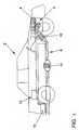
- the single FIGURE schematically shows a motor vehicle with an internal combustion engine, in whose exhaust gas system behind one another an SCR catalytic converter and a CSF particle filter are arranged.
- the motor vehicle 2 shown schematically in the figure is driven by a diesel engine 4.
- the diesel engine 4 is equipped with a Abgas turbocharger'6, which uses the exhaust gases of the diesel engine 4 in a known manner to charge this.
- the exhaust gases are discharged through an exhaust system designated 8 as a whole into the environment.
- an SCR catalytic converter 10 is arranged directly behind the diesel engine 4, in which the exhaust gases are de-embroidered in a first process step.
- the SCR catalytic converter 10 operates with urea or an aqueous urea solution as reducing agent, which is taken from a urea tank 12 arranged, for example, in the rear of the vehicle and injected into the exhaust gas line 8 before the SCR catalytic converter 10.
- the urea SCR catalyst 10 operates at an exhaust gas temperature well within the heat tolerability limits of the SCR catalyst in an effective area of the SCR work window.
- a regenerable particle filter 14 is arranged in the exhaust gas line, which removes soot particles from the exhaust gas.
- the particulate filter 14 is a particulate filter of the CSF type, which is coated with a catalytically active material.
- the particle filter 14 is regenerated by means of fuel, which is taken from the fuel tank 16 of the motor vehicle 2 and injected into the exhaust gas line 8 before the particle filter 14. Through a regulated metering of the fuel injection, the particulate filter can be operated at an optimum temperature for soot burn-off
Description
- Die vorliegende Erfindung betrifft ein Verfahren zur Abgasnachbehandlung bei Dieselmotoren oder dergleichen, bei welchem das Abgas durch einen jeweils im Abgasstrang angeordneten regenerierbaren Partikelfilter sowie einen NOx-Katalysator geleitet wird, sowie eine Vorrichtung zum Durchführen dieses Verfahrens. Unter dem Begriff "Dieselmotoren oder dergleichen" werden Motoren verstanden, deren Abgase nicht vernachlässigbare Mengen an Rußpartikeln oder ähnlichen Verbrennungsrückständen enthalten.
- Es ist bereits bekannt, den Gehalt an Rußpartikeln und Stickoxiden im Abgas durch getrennte Aggregate so weit abzusenken, dass das Abgas den gesetzlich vorgeschriebenen Abgasgrenzwerten entspricht.
- Eine seit Jahren erprobe Technologie zur NOx-Minderung ist die Harnstoff-SCR-Technologie (SCR = selective catalytic reduction). Dabei wird Harnstoff bzw. eine wässrige Harnstofflösung über ein Dosiersystem vor dem NOx-Katalysator in den Abgasstrang eingebracht, wobei dann im NOx-Katalysator in zwei chemischen Schritten Ammoniak entsteht, welches wiederum mit den im NOx-Katalysator gesammelten Stickoxiden zu Stickstoff reagiert. Der Vorteil einer Verwendung von Harnstoff liegt darin, dass der Umgang bei Transport und Lagerung völlig problemlos ist, da Harnstoff farblos, geruchsfrei, ungiftig und biologisch unbedenklich ist.
- Zum Ausfiltern von Rußpartikeln aus dem Abgas haben sich Partikelfilter vom CSF-Typ bewährt (CSF = catalysed soot filter). Es handelt sich dabei um Partikelfilter, die eine katalytische Beschichtung aufweisen, um den Rußabbrand zu verbessern bzw. zu ermöglichen. Partikelfilter vom CSF-Typ sind passive, d.h. kontinuierlich arbeitende Systeme mit einer hohen Lebensdauer. Ein weiterer Vorteil ist ihr geringer Bauraumbedarf.
- NOx-Katalysatoren vom SCR-Typ einerseits und Partikelfilter vom CSF-Typ andererseits sind deshalb besonders für die Verwendung in Kraftfahrzeugen geeignet. Es sind bereits in der Literatur Anlagen diskutiert worden, bei denen ein Partikelfilter vom CSF-Typ und ein NOx-Katalysator vom SCR-Typ bezüglich der Strömungsrichtung des Abgases hintereinander im Abgasstrang angeordnet sind. Eine motornahe Anordnung des Partikelfilters gewährleistet wegen der verhältnismäßig hohen Abgastemperatur einen zuverlässigen Rußabbrand. Ein problem ergibt sich jedoch aus der motorfernen Anordnung des SCR-Katalysators. Die Harnstoff-SCR-Technologie kann erst ab einer Abgastemperatur von mehr als 200°C hinreichend stabil eingesetzt werden. Unterhalb dieser Temperatur kann kein frische Reduktionsmittel in den Abgasstrang eingespritzt werden, da eine-vollständige Auflösung der Harnstofflösung im Abgasstrang bei Temperaturen unter 200°C nicht-gewährleistet ist. Es kann dann nämlich zu einer Polymerisation des Harnstoffes kommen, die zu irreversiblen Ablagerungen im Abgasstrang führt und diesen im Laufe der Zeit verstopft.
- Das bedeutet, dass eine nennenswerte Entstickung des Abgases erst einsetzen kann, nachdem der SCR-Katalysator nach einer bestimmten Betriebszeit auf eine ausreichende Temperatur aufgeheizt worden ist. Bei einem MVEG-Testzyklus (MVEG = motor vehicle emissions group), bei welchem die Abgastemperatur an dem nachgeordneten SCR-Katalysator sehr lange unterhalb von 200°C bleibt, ist deshalb nur eine verhältnismäßig niedrige Entstickungsrate zu erwarten.
- Aus der
EP 1.469 173 A1 ist ein System zum Temperaturmanagement eines Dieselmotors bekannt, bei dem stromaufwärts eines SCR-Katalysotors ein steuerbarer Wärmetauscher sowie eine zusätzliche Wärmequelle vorgesehen sind. Stromaufwärts des Wärmetauschers ist ein Dieseloxidationskatalysator angeordnet, während stromabwärts des SCR-Katalysators ein Dieselpartikelfilter angeordnet ist. - Es ist die Aufgabe der vorliegenden Erfindung, ein Verfahren der im Oberbegriff des Anspruches 1 genannten Art sowie eine Vorrichtung zur Durchführung dieses Verfahrens zu schaffen, bei denen der Wirkungsgrad des SCR-Katalysators in allen Betriebsbereichen verbessert wird, wobei gleichzeitig ein ordnungsgemäßer Betrieb des CSF-Partikelfilters gewährleistet ist.
- Diese Aufgabe ist erfindungsgemäß durch ein Verfahren mit den Merkmalen des Anspruches 1 sowie eine Vorrichtung mit den Merkmalen des Anspruches 3 gelöst. Bevorzugte Ausgestaltungen der Erfindung sind Gegenstand der Unteransprüche.
- Das erfindungsgemäße Verfahren sieht vor, dass das Abgas zuerst durch einen motornah angeordneten NOx-Katalysator vom Harnstoff-SCR-Typ und anschließend durch einen Partikelfilter vom CSF-Typ geleitet wird, wobei dem Partikelfilter die für seine Regeneration erforderliche Energie von außen zugeführt wird.
- Durch die motornahe Anordnung des SCR-Katalysators wird infolge der höheren Abgastemperatur das Arbeitsfenster des Katalysators besser genutzt; die Konvertierung der Stickoxide beginnt früher, was zu einer Steigerung der Entstickungsrate über die gesamte Betriebszeit (beispielsweise einen MVEG-Testzyklus) führt. Der für die Regeneration erforderliche Harnstoff wird vor dem SCR-Katalysator in den Abgasstrang gespritzt.
- Um trotz der motorfernen Anordnung des CSF-Partikelfilters dessen ordnungsgemäßen Betrieb sicherzustellen, wird diesem die für seine Regeneration erforderliche Energie von außen zugeführt. Diese Energie kann in unterschiedlicher Weise zugeführt werden, nämlich etwa in Form von Wärmeenergie mittels Mikrowellen- oder Elektro-Heizeinrichtungen, oder in der Form von Brennstoffen, die mit dem im Abgas enthaltenen Sauerstoffüberschuss reagieren. In einer bevorzugten Ausgestaltung der Erfindung ist vorgesehen, dass als Regenerationsmittel für den CSF-Partikelfilter der für den Betrieb des Motors vorgesehene Kraftstoff verwendet wird, da dieser im Betrieb immer zur Verfügung steht und beispielsweise keine gesonderten Tanks erfordert. Die Regeneration des Partikelfilters kann dabei jedoch nicht über eine vom Motormanagement gesteuerte Gemischanreicherung erfolgen, da die daraus resultierenden Abgastemperaturen von über 650°C, die sich etwas vermindert auch im SCR-Katalysator einstellen, deutlich an dessen Toleranzgrenzen liegen würden. Darüber hinaus würde eine durch Nacheinspritzen verursachte erhöhte Kohlenwasserstoffkonzentration beim Überleiten über bestimmte Typen von SCR-Katalysator zu einer Vergiftung des Katalysators und damit zu Einbußen im Wirkungsgrad führen.
- Gemäß der Erfindung ist deshalb vorgesehen, dass der Kraftstoff vor dem Partikelfilter in den Abgasstrang eingespritzt wird (HCl-Verfahren).
- Mit dem erfindungsgemäßen Verfahren wird deshalb in vorteilhafter Weise eine gute Ausnutzung des Arbeitsfensters des SCR-Katalysators einerseits und eine motorschonende Partikelfilter-Regeneration andererseits erzielt.
- Eine Vorrichtung gemäß dem Oberbegriff des Anspruches 3 ist erfindungsgemäß gekennzeichnet durch einen motomah angeordneten NOx-Katalysator vom Harnstoff-SCR-Typ und einen stromabwärts davon angeordneten Partikelfilter vom CSF-Typ, und durch eine dem Partikelfilter zugeordnete Einrichtung zum Zuführen der für seine Regeneration erforderlich Energie. Wie bereits weiter vorne ausgeführt wurde, ist gemäß einer bevorzugten Ausgestaltung der Erfindung eine Einrichtung vorgesehen, um vor dem Partikelfilter Kraftstoff in den Abgasstrang einzuspritzen. Als Kraftstoff wird vorzugsweise der für den Betrieb des Dieselmotors vorgesehene Kraftstoff verwendet, so dass die Einrichtung zum Einspritzen von Kraftstoff direkt an den Kraftstofftank des Dieselmotors angeschlossen sein kann und ein gesonderter Kraftstofftank nicht erforderlich ist.
- Wenn die beschriebene Vorrichtung zur Abgasnachbehandlung bei einem Kraftfahrzeug verwendet wird, ist gemäß einer weiteren Ausgestaltung der Erfindung vorgesehen, dass der Partikelfilter im Unterbodenbereich des Kraftfahrzeuges angeordnet ist, wo die von diesem abgegebene Wärme direkt an die Umgebung abgeführt .werden kann.
- Ein Ausführungsbeispiel der Erfindung ist in der Zeichnung dargestellt und im folgenden näher beschrieben.
- Die einzige Figur zeigt schematisch ein Kraftfahrzeug mit einem Verbrennungsmotor, in dessen Abgasstrang hintereinander ein SCR-Katalysator und ein CSF-Partikelfilter angeordnet sind.
- Das in der Figur schematisch dargestellte Kraftfahrzeug 2 wird durch einen Dieselmotor 4 angetrieben. Wie ebenfalls schematisch dargestellt ist, ist der Dieselmotor 4 mit einem Abgasturbolader'6 ausgestattet, welcher in bekannter Weise die Abgase des Dieselmotors 4 nutzt, um diesen aufzuladen.
- Die Abgase werden durch einen als Ganzes mit 8 bezeichneten Abgasstrang in die Umgebung abgeführt. In diesem Abgasstrang 8 ist unmittelbar hinter dem Dieselmotor 4 ein SCR-Katalysator 10 angeordnet, in welchem die Abgase in einem ersten Verfahrensschritt entstickt werden. Der SCR-Katalysator 10 arbeitet mit Harnstoff bzw. einer wässrigen Harnstofflösung als Reduktionsmittel, welche, einem beispielsweise im Heck des Fahrzeuges angeordneten Hamstofftank 12 entnommen und vor dem SCR-Katalysator 10 in den Abgasstrang 8 eingespritzt wird. Der Harnstoff SCR-Katalysator 10 arbeitet bei einer Abgastemperatur deutlich innerhalb der Wärmeverträglichkeitsgrenzen des SCR-Katalysators in einem wirksamen Bereich des SCR-Arbeitsfensters.
- Stromabwärts des SCR-Katalysators ist im Abgasstrang ein regenerierbarer Partikelfilter 14 angeordnet, welcher dem Abgas Rußpartikel entzieht. Der Partikelfilter 14 ist ein Partikelfilter vom CSF-Typ, welcher mit einem katalytisch aktiven Material beschichtet ist. Der Partikelfilter 14 wird mittels Kraftstoff regeneriert, welcher dem Kraftstofftank 16 des Kraftfahrzeug 2 entnommen und vor dem Partikelfilter 14 in den Abgasstrang 8 eingespritzt wird. Durch eine geregelte Dosierung der Kraftstoffeinspritzung kann der Partikelfilter bei einer für den Rußabbrand optimalen Temperatur betrieben werden
-
- 2
- Kraftfahrzeug
- 4
- Dieselmotors
- 6
- Abgasturbolader
- 8
- Abgasstrang
- 10
- SCR-Katalysator
- 12
- Harnstofftank
- 14
- Partikelfilter
- 16
- Kraftstofftank
Claims (6)
- Verfahren zur Abgasnachbehandlung bei Dieselmotoren oder dergleichen, bei welchem das Abgas durch einen jeweils im Abgasstrang angeordneten regenerierbaren Partikelfilter sowie einen NOx-Katalysator geleitet wird, dadurch gekennzeichnet, dass das Abgas zuerst durch einen unmittelbar nach dem Dieselmotor angeordneten NOx-Katalysator (10) vom Harnstoff-SCR-Typ (SCR = selective catalytic reduction) und anschließend durch einen Partikelfilter (14) vom CSF-Typ (CSF = catalysed soot filter) geleitet wird, wobei dem Partikelfilter (14) die für seine Regeneration erforderliche Energie von außen zugeführt wird.
- Verfahren nach Anspruch 1, dadurch gekennzeichnet, dass vor dem Partikelfilter (14) Kraftstoff in den Abgasstrang (8) eingespritzt wird.
- Vorrichtung zur Abgasnachbehandlung bei Dieselmotoren oder dergleichen, umfassend einen jeweils im Abgasstrang angeordneten regenerierbaren Partikelfilter sowie einen NOx-Katalysator, gekennzeichnet durch einen unmittelbar nach dem Dieselmotor angeordneten NOx-Katalysator (10) vom Harnstoff SCR-Typ und einen stromabwärts davon angeordneten Partikelfilter (14) vom CSF-Typ, und durch eine dem Partikelfilter (14) zugeordnete Einrichtung zum Zuführen der für seine Regeneration erforderlichen Energie.
- Vorrichtung nach Anspruch 3, gekennzeichnet durch eine Einrichtung zum Einspritzen von Kraftstoff vor dem Partikelfilter (14) in den Abgasstrang (8).
- Vorrichtung nach Anspruch 4, dadurch gekennzeichnet, dass die Einrichtung zum Einspritzen von Kraftstoff an den Kraftstofftank (16) des Dieselmotors (4) angeschlossen ist.
- Vorrichtung nach einem der Ansprüche 3 bis 5 zur Verwendung in einem Kraftfahrzeug, dadurch gekennzeichnet, dass der Partikelfilter (14) im Unterbodenbereich des Kraftfahrzeuges (2) angeordnet ist.
Applications Claiming Priority (2)
| Application Number | Priority Date | Filing Date | Title |
|---|---|---|---|
| DE102005009686A DE102005009686A1 (de) | 2005-03-03 | 2005-03-03 | Verfahren zur Abgasnachbehandlung bei Dieselmotoren oder dergleichen, und Vorrichtung zur Durchführung dieses Verfahrens |
| PCT/EP2006/000591 WO2006092190A1 (de) | 2005-03-03 | 2006-01-24 | Verfahren zur abgasnachbehandlung bei dieselmotoren oder dergleichen, und vorrichtung zur durchführung dieses verfahrens |
Publications (2)
| Publication Number | Publication Date |
|---|---|
| EP1859131A1 EP1859131A1 (de) | 2007-11-28 |
| EP1859131B1 true EP1859131B1 (de) | 2008-10-08 |
Family
ID=36007394
Family Applications (1)
| Application Number | Title | Priority Date | Filing Date |
|---|---|---|---|
| EP06704442A Not-in-force EP1859131B1 (de) | 2005-03-03 | 2006-01-24 | Verfahren zur abgasnachbehandlung bei dieselmotoren oder dergleichen, und vorrichtung zur durchführung dieses verfahrens |
Country Status (5)
| Country | Link |
|---|---|
| US (1) | US20080041041A1 (de) |
| EP (1) | EP1859131B1 (de) |
| AT (1) | ATE410589T1 (de) |
| DE (2) | DE102005009686A1 (de) |
| WO (1) | WO2006092190A1 (de) |
Families Citing this family (6)
| Publication number | Priority date | Publication date | Assignee | Title |
|---|---|---|---|---|
| DE102007019912A1 (de) | 2007-04-27 | 2008-11-06 | Daimler Ag | Anordnung eines Bauteils an einer Unterseite eines Personenkraftwagens |
| DE102008022517A1 (de) * | 2008-05-07 | 2009-11-12 | Emitec Gesellschaft Für Emissionstechnologie Mbh | Vorrichtung zur Bereitstellung von Reduktionsmittellösung in ein Abgassystem und entsprechendes Abgassystem |
| DE102009014236B4 (de) | 2009-03-20 | 2016-12-29 | Audi Ag | Vorrichtung zur Abgasreinigung für eine Brennkraftmaschine |
| CH699643B1 (de) * | 2009-08-05 | 2010-04-15 | Hochschule Rapperswil Inst Fue | Verfahren und Vorrichtung zur Regeneration von Partikelfiltern. |
| US9046019B2 (en) | 2011-11-04 | 2015-06-02 | GM Global Technology Operations LLC | System and method for particulate filter regeneration |
| EP2826971A1 (de) | 2013-07-17 | 2015-01-21 | DEUTZ Aktiengesellschaft | Verfahren zur Verminderung von Stickoxiden in dieselmotorischen Abgasen und Abgasnachbehandlungssystem zur Durchführung des Verfahrens |
Family Cites Families (11)
| Publication number | Priority date | Publication date | Assignee | Title |
|---|---|---|---|---|
| DE3720829A1 (de) * | 1987-06-24 | 1989-01-05 | Zeuna Staerker Kg | Verfahren und vorrichtung zum reinigen eines russfilters |
| US4902487A (en) * | 1988-05-13 | 1990-02-20 | Johnson Matthey, Inc. | Treatment of diesel exhaust gases |
| US6826906B2 (en) * | 2000-08-15 | 2004-12-07 | Engelhard Corporation | Exhaust system for enhanced reduction of nitrogen oxides and particulates from diesel engines |
| JP3788501B2 (ja) * | 2001-06-28 | 2006-06-21 | 三菱ふそうトラック・バス株式会社 | 内燃機関の排気浄化装置 |
| US6928806B2 (en) * | 2002-11-21 | 2005-08-16 | Ford Global Technologies, Llc | Exhaust gas aftertreatment systems |
| DE10300298A1 (de) * | 2003-01-02 | 2004-07-15 | Daimlerchrysler Ag | Abgasnachbehandlungseinrichtung und -verfahren |
| US7031827B2 (en) * | 2003-04-11 | 2006-04-18 | Ford Global Technologies, Llc | Computer algorithm to estimate particulate filter regeneration rates |
| US6871489B2 (en) * | 2003-04-16 | 2005-03-29 | Arvin Technologies, Inc. | Thermal management of exhaust systems |
| US7155331B1 (en) * | 2003-12-15 | 2006-12-26 | Donaldson Company, Inc. | Method of prediction of NOx mass flow in exhaust |
| DE102004036036A1 (de) * | 2004-07-24 | 2006-03-16 | Daimlerchrysler Ag | Abgassystem, insbesondere für eine Brennkraftmaschine eines Kraftfahrzeugs |
| DE202005001257U1 (de) * | 2004-09-17 | 2005-04-07 | Arvinmeritor Emissions Tech | Abgasanlage eines Kfzs mit Dieselmotor |
-
2005
- 2005-03-03 DE DE102005009686A patent/DE102005009686A1/de not_active Withdrawn
-
2006
- 2006-01-24 AT AT06704442T patent/ATE410589T1/de not_active IP Right Cessation
- 2006-01-24 US US11/885,602 patent/US20080041041A1/en not_active Abandoned
- 2006-01-24 WO PCT/EP2006/000591 patent/WO2006092190A1/de active Application Filing
- 2006-01-24 DE DE502006001752T patent/DE502006001752D1/de active Active
- 2006-01-24 EP EP06704442A patent/EP1859131B1/de not_active Not-in-force
Also Published As
| Publication number | Publication date |
|---|---|
| DE102005009686A1 (de) | 2006-09-07 |
| WO2006092190A1 (de) | 2006-09-08 |
| DE502006001752D1 (de) | 2008-11-20 |
| US20080041041A1 (en) | 2008-02-21 |
| EP1859131A1 (de) | 2007-11-28 |
| ATE410589T1 (de) | 2008-10-15 |
Similar Documents
| Publication | Publication Date | Title |
|---|---|---|
| EP2138681B1 (de) | Verfahren und Vorrichtung zur Reinigung von Dieselabgasen | |
| DE102014103678B4 (de) | Kompaktes abgasbehandlungssystem für einen dieselmotor | |
| EP2568137B1 (de) | Beheiztes Injektionssystem für Dieselmotor-Abgassysteme | |
| DE102011012401A1 (de) | Gas/Flüssigkeits-Mischvorrichtung für Abgasnachbehandlung | |
| DE102013200361B4 (de) | Abgasnachbehandlungssystem, Kraftfahrzeug und Verfahren zur Abgasnachbehandlung | |
| DE102008040000B4 (de) | Vorrichtung für die Reduktion von in Abgas enthaltenem Stickstoffoxid und Verwendung | |
| WO2017088958A1 (de) | Abgasnachbehandlungseinrichtung für eine verbrennungskraftmaschine sowie verfahren zum betreiben einer antriebseinrichtung mit einer solchen abgasnachbehandlungseinrichtung | |
| DE102015200023A1 (de) | Verwendung einer stromaufwärts eines Stickoxidspeicherkatalysators angeordneten elektrischen Heizvorrichtung | |
| EP1859131B1 (de) | Verfahren zur abgasnachbehandlung bei dieselmotoren oder dergleichen, und vorrichtung zur durchführung dieses verfahrens | |
| DE102015212485B4 (de) | Abgastrakt mit gegen eine Strömungsrichtung spritzende Dosiereinrichtung, Verfahren zum Betrieb eines Abgastraktes sowie Fahrzeug mit Abgastrakt | |
| DE102009035304C5 (de) | System zur Reinigung von Abgas | |
| EP1554474A2 (de) | Abgasreinigungsanlage einer brennkraftmaschine und verfahren zur reinigung deren abgase | |
| DE212015000170U1 (de) | Abgasnachbehandlungssystem für einen Dieselmotor | |
| DE102018126621A1 (de) | Abgasnachbehandlungssystem sowie Verfahren zur Abgasnachbehandlung eines Verbrennungsmotors | |
| DE102018220121A1 (de) | Abgasnachbehandlungssystem und Verfahren zur Abgasnachbehandlung eines Verbrennungsmotors | |
| DE102007056202A1 (de) | Abgasnachbehandlungseinrichtung für eine Brennkraftmaschine und Verfahren zur Nachbehandlung von Abgasen einer Brennkraftmaschine | |
| DE102017008695A1 (de) | Verfahren zum Betreiben einer Abgasanlage, insbesondere eines Kraftfahrzeugs | |
| EP1957767B1 (de) | Verfahren zur abgasnachbehandlung bei verbrennungsmotoren, und vorrichtung zur durchführung dieses verfahrens | |
| DE102018119047B4 (de) | Verfahren zur bestimmung der russbeladung in einer partikelfiltervorrichtung mit selektiver katalytischer reduktion | |
| DE102014221322A1 (de) | Abgasbehandlungseinrichtung für eine Abgasanlage einer Brennkraftmaschine | |
| DE102018132833A1 (de) | Verfahren zur Abgasnachbehandlung eines Verbrennungsmotors sowie Abgasnachbehandlungssystem | |
| DE102015106947A1 (de) | Abgasreinigungssystem für ein Fahrzeug | |
| DE102020128786A1 (de) | Verfahren zur Verminderung der Lachgasemissionen eines Verbrennungsmotors sowie Abgasnachbehandlungssystem | |
| EP3428414B1 (de) | Vorrichtung und verfahren für abgasreinigungssysteme von dieselfahrzeugen, insbesondere zur nachrüstung von diesel-bestandsfahrzeugen mit einem dieselpartikelfilter, insbesondere für den innerstädtischen fahrbetrieb | |
| DE10361220B4 (de) | Verfahren zum Regenerieren eines Partikelfilters |
Legal Events
| Date | Code | Title | Description |
|---|---|---|---|
| PUAI | Public reference made under article 153(3) epc to a published international application that has entered the european phase |
Free format text: ORIGINAL CODE: 0009012 |
|
| 17P | Request for examination filed |
Effective date: 20071004 |
|
| AK | Designated contracting states |
Kind code of ref document: A1 Designated state(s): AT BE BG CH CY CZ DE DK EE ES FI FR GB GR HU IE IS IT LI LT LU LV MC NL PL PT RO SE SI SK TR |
|
| RIN1 | Information on inventor provided before grant (corrected) |
Inventor name: DUESTERDIEK, THORSTEN Inventor name: JUTKA, CARSTEN Inventor name: FREITAG, ACHIM Inventor name: KOESTERS, MARTINA |
|
| 17Q | First examination report despatched |
Effective date: 20071227 |
|
| R17C | First examination report despatched (corrected) |
Effective date: 20080111 |
|
| DAX | Request for extension of the european patent (deleted) | ||
| GRAP | Despatch of communication of intention to grant a patent |
Free format text: ORIGINAL CODE: EPIDOSNIGR1 |
|
| GRAS | Grant fee paid |
Free format text: ORIGINAL CODE: EPIDOSNIGR3 |
|
| GRAA | (expected) grant |
Free format text: ORIGINAL CODE: 0009210 |
|
| AK | Designated contracting states |
Kind code of ref document: B1 Designated state(s): AT BE BG CH CY CZ DE DK EE ES FI FR GB GR HU IE IS IT LI LT LU LV MC NL PL PT RO SE SI SK TR |
|
| REG | Reference to a national code |
Ref country code: GB Ref legal event code: FG4D Free format text: NOT ENGLISH |
|
| REG | Reference to a national code |
Ref country code: CH Ref legal event code: EP |
|
| REG | Reference to a national code |
Ref country code: IE Ref legal event code: FG4D Free format text: LANGUAGE OF EP DOCUMENT: GERMAN |
|
| REF | Corresponds to: |
Ref document number: 502006001752 Country of ref document: DE Date of ref document: 20081120 Kind code of ref document: P |
|
| PG25 | Lapsed in a contracting state [announced via postgrant information from national office to epo] |
Ref country code: SI Free format text: LAPSE BECAUSE OF FAILURE TO SUBMIT A TRANSLATION OF THE DESCRIPTION OR TO PAY THE FEE WITHIN THE PRESCRIBED TIME-LIMIT Effective date: 20081008 |
|
| NLV1 | Nl: lapsed or annulled due to failure to fulfill the requirements of art. 29p and 29m of the patents act | ||
| PG25 | Lapsed in a contracting state [announced via postgrant information from national office to epo] |
Ref country code: ES Free format text: LAPSE BECAUSE OF FAILURE TO SUBMIT A TRANSLATION OF THE DESCRIPTION OR TO PAY THE FEE WITHIN THE PRESCRIBED TIME-LIMIT Effective date: 20090119 Ref country code: BG Free format text: LAPSE BECAUSE OF FAILURE TO SUBMIT A TRANSLATION OF THE DESCRIPTION OR TO PAY THE FEE WITHIN THE PRESCRIBED TIME-LIMIT Effective date: 20090108 Ref country code: LT Free format text: LAPSE BECAUSE OF FAILURE TO SUBMIT A TRANSLATION OF THE DESCRIPTION OR TO PAY THE FEE WITHIN THE PRESCRIBED TIME-LIMIT Effective date: 20081008 |
|
| PG25 | Lapsed in a contracting state [announced via postgrant information from national office to epo] |
Ref country code: LV Free format text: LAPSE BECAUSE OF FAILURE TO SUBMIT A TRANSLATION OF THE DESCRIPTION OR TO PAY THE FEE WITHIN THE PRESCRIBED TIME-LIMIT Effective date: 20081008 Ref country code: PT Free format text: LAPSE BECAUSE OF FAILURE TO SUBMIT A TRANSLATION OF THE DESCRIPTION OR TO PAY THE FEE WITHIN THE PRESCRIBED TIME-LIMIT Effective date: 20090218 Ref country code: IS Free format text: LAPSE BECAUSE OF FAILURE TO SUBMIT A TRANSLATION OF THE DESCRIPTION OR TO PAY THE FEE WITHIN THE PRESCRIBED TIME-LIMIT Effective date: 20090208 Ref country code: PL Free format text: LAPSE BECAUSE OF FAILURE TO SUBMIT A TRANSLATION OF THE DESCRIPTION OR TO PAY THE FEE WITHIN THE PRESCRIBED TIME-LIMIT Effective date: 20081008 Ref country code: FI Free format text: LAPSE BECAUSE OF FAILURE TO SUBMIT A TRANSLATION OF THE DESCRIPTION OR TO PAY THE FEE WITHIN THE PRESCRIBED TIME-LIMIT Effective date: 20081008 Ref country code: NL Free format text: LAPSE BECAUSE OF FAILURE TO SUBMIT A TRANSLATION OF THE DESCRIPTION OR TO PAY THE FEE WITHIN THE PRESCRIBED TIME-LIMIT Effective date: 20081008 |
|
| REG | Reference to a national code |
Ref country code: IE Ref legal event code: FD4D |
|
| PG25 | Lapsed in a contracting state [announced via postgrant information from national office to epo] |
Ref country code: EE Free format text: LAPSE BECAUSE OF FAILURE TO SUBMIT A TRANSLATION OF THE DESCRIPTION OR TO PAY THE FEE WITHIN THE PRESCRIBED TIME-LIMIT Effective date: 20081008 Ref country code: IE Free format text: LAPSE BECAUSE OF FAILURE TO SUBMIT A TRANSLATION OF THE DESCRIPTION OR TO PAY THE FEE WITHIN THE PRESCRIBED TIME-LIMIT Effective date: 20081008 Ref country code: DK Free format text: LAPSE BECAUSE OF FAILURE TO SUBMIT A TRANSLATION OF THE DESCRIPTION OR TO PAY THE FEE WITHIN THE PRESCRIBED TIME-LIMIT Effective date: 20081008 Ref country code: RO Free format text: LAPSE BECAUSE OF FAILURE TO SUBMIT A TRANSLATION OF THE DESCRIPTION OR TO PAY THE FEE WITHIN THE PRESCRIBED TIME-LIMIT Effective date: 20081008 |
|
| PLBE | No opposition filed within time limit |
Free format text: ORIGINAL CODE: 0009261 |
|
| STAA | Information on the status of an ep patent application or granted ep patent |
Free format text: STATUS: NO OPPOSITION FILED WITHIN TIME LIMIT |
|
| PG25 | Lapsed in a contracting state [announced via postgrant information from national office to epo] |
Ref country code: CZ Free format text: LAPSE BECAUSE OF FAILURE TO SUBMIT A TRANSLATION OF THE DESCRIPTION OR TO PAY THE FEE WITHIN THE PRESCRIBED TIME-LIMIT Effective date: 20081008 Ref country code: MC Free format text: LAPSE BECAUSE OF NON-PAYMENT OF DUE FEES Effective date: 20090131 Ref country code: SE Free format text: LAPSE BECAUSE OF FAILURE TO SUBMIT A TRANSLATION OF THE DESCRIPTION OR TO PAY THE FEE WITHIN THE PRESCRIBED TIME-LIMIT Effective date: 20090108 |
|
| 26N | No opposition filed |
Effective date: 20090709 |
|
| PG25 | Lapsed in a contracting state [announced via postgrant information from national office to epo] |
Ref country code: SK Free format text: LAPSE BECAUSE OF FAILURE TO SUBMIT A TRANSLATION OF THE DESCRIPTION OR TO PAY THE FEE WITHIN THE PRESCRIBED TIME-LIMIT Effective date: 20081008 |
|
| PG25 | Lapsed in a contracting state [announced via postgrant information from national office to epo] |
Ref country code: BE Free format text: LAPSE BECAUSE OF NON-PAYMENT OF DUE FEES Effective date: 20090131 |
|
| PG25 | Lapsed in a contracting state [announced via postgrant information from national office to epo] |
Ref country code: AT Free format text: LAPSE BECAUSE OF NON-PAYMENT OF DUE FEES Effective date: 20090124 |
|
| REG | Reference to a national code |
Ref country code: CH Ref legal event code: PL |
|
| GBPC | Gb: european patent ceased through non-payment of renewal fee |
Effective date: 20100124 |
|
| PG25 | Lapsed in a contracting state [announced via postgrant information from national office to epo] |
Ref country code: GR Free format text: LAPSE BECAUSE OF FAILURE TO SUBMIT A TRANSLATION OF THE DESCRIPTION OR TO PAY THE FEE WITHIN THE PRESCRIBED TIME-LIMIT Effective date: 20090109 Ref country code: LI Free format text: LAPSE BECAUSE OF NON-PAYMENT OF DUE FEES Effective date: 20100131 Ref country code: CH Free format text: LAPSE BECAUSE OF NON-PAYMENT OF DUE FEES Effective date: 20100131 |
|
| PG25 | Lapsed in a contracting state [announced via postgrant information from national office to epo] |
Ref country code: GB Free format text: LAPSE BECAUSE OF NON-PAYMENT OF DUE FEES Effective date: 20100124 |
|
| PG25 | Lapsed in a contracting state [announced via postgrant information from national office to epo] |
Ref country code: LU Free format text: LAPSE BECAUSE OF NON-PAYMENT OF DUE FEES Effective date: 20090124 |
|
| PG25 | Lapsed in a contracting state [announced via postgrant information from national office to epo] |
Ref country code: TR Free format text: LAPSE BECAUSE OF FAILURE TO SUBMIT A TRANSLATION OF THE DESCRIPTION OR TO PAY THE FEE WITHIN THE PRESCRIBED TIME-LIMIT Effective date: 20081008 |
|
| PG25 | Lapsed in a contracting state [announced via postgrant information from national office to epo] |
Ref country code: CY Free format text: LAPSE BECAUSE OF FAILURE TO SUBMIT A TRANSLATION OF THE DESCRIPTION OR TO PAY THE FEE WITHIN THE PRESCRIBED TIME-LIMIT Effective date: 20081008 |
|
| PGFP | Annual fee paid to national office [announced via postgrant information from national office to epo] |
Ref country code: FR Payment date: 20120216 Year of fee payment: 7 Ref country code: HU Payment date: 20120109 Year of fee payment: 7 |
|
| PGFP | Annual fee paid to national office [announced via postgrant information from national office to epo] |
Ref country code: DE Payment date: 20120131 Year of fee payment: 7 |
|
| PGFP | Annual fee paid to national office [announced via postgrant information from national office to epo] |
Ref country code: IT Payment date: 20120125 Year of fee payment: 7 |
|
| REG | Reference to a national code |
Ref country code: FR Ref legal event code: ST Effective date: 20130930 |
|
| PG25 | Lapsed in a contracting state [announced via postgrant information from national office to epo] |
Ref country code: HU Free format text: LAPSE BECAUSE OF NON-PAYMENT OF DUE FEES Effective date: 20130125 Ref country code: DE Free format text: LAPSE BECAUSE OF NON-PAYMENT OF DUE FEES Effective date: 20130801 |
|
| REG | Reference to a national code |
Ref country code: DE Ref legal event code: R119 Ref document number: 502006001752 Country of ref document: DE Effective date: 20130801 |
|
| PG25 | Lapsed in a contracting state [announced via postgrant information from national office to epo] |
Ref country code: FR Free format text: LAPSE BECAUSE OF NON-PAYMENT OF DUE FEES Effective date: 20130131 |
|
| PG25 | Lapsed in a contracting state [announced via postgrant information from national office to epo] |
Ref country code: IT Free format text: LAPSE BECAUSE OF NON-PAYMENT OF DUE FEES Effective date: 20130124 |