EP1854165B3 - Verfahren zum ausgewogenen aufladen einer lithiumionen- oder lithium-polymer-batterie - Google Patents
Verfahren zum ausgewogenen aufladen einer lithiumionen- oder lithium-polymer-batterie Download PDFInfo
- Publication number
- EP1854165B3 EP1854165B3 EP06709396.3A EP06709396A EP1854165B3 EP 1854165 B3 EP1854165 B3 EP 1854165B3 EP 06709396 A EP06709396 A EP 06709396A EP 1854165 B3 EP1854165 B3 EP 1854165B3
- Authority
- EP
- European Patent Office
- Prior art keywords
- cell
- cells
- voltage
- charge
- charging
- Prior art date
- Legal status (The legal status is an assumption and is not a legal conclusion. Google has not performed a legal analysis and makes no representation as to the accuracy of the status listed.)
- Not-in-force
Links
Images


Classifications
-
- H—ELECTRICITY
- H01—ELECTRIC ELEMENTS
- H01M—PROCESSES OR MEANS, e.g. BATTERIES, FOR THE DIRECT CONVERSION OF CHEMICAL ENERGY INTO ELECTRICAL ENERGY
- H01M10/00—Secondary cells; Manufacture thereof
- H01M10/42—Methods or arrangements for servicing or maintenance of secondary cells or secondary half-cells
- H01M10/44—Methods for charging or discharging
- H01M10/441—Methods for charging or discharging for several batteries or cells simultaneously or sequentially
-
- Y—GENERAL TAGGING OF NEW TECHNOLOGICAL DEVELOPMENTS; GENERAL TAGGING OF CROSS-SECTIONAL TECHNOLOGIES SPANNING OVER SEVERAL SECTIONS OF THE IPC; TECHNICAL SUBJECTS COVERED BY FORMER USPC CROSS-REFERENCE ART COLLECTIONS [XRACs] AND DIGESTS
- Y02—TECHNOLOGIES OR APPLICATIONS FOR MITIGATION OR ADAPTATION AGAINST CLIMATE CHANGE
- Y02E—REDUCTION OF GREENHOUSE GAS [GHG] EMISSIONS, RELATED TO ENERGY GENERATION, TRANSMISSION OR DISTRIBUTION
- Y02E60/00—Enabling technologies; Technologies with a potential or indirect contribution to GHG emissions mitigation
- Y02E60/10—Energy storage using batteries
Definitions
- the present invention relates to the field of charging or charging rechargeable batteries, and relates to a charging method or load balanced, over time, the cells of a lithium-ion battery or lithium polymer.
- the optimized electric charging of batteries comprising several constituent cells poses problems that are difficult to solve, especially when the number of elements or cells placed in series is high.
- GB 2,372,645 and US 5,773,959 disclose a lithium battery charging device comprising a cell charge control system.
- the lithium-ion and lithium polymer batteries do not accept overload during charging or under load during use (discharge).
- the maximum voltage value adopted, by way of example and not limitation, for the overload for each of the elements of a lithium-ion battery and lithium polymer in series is 4.20 volts and the voltage used to stop the discharge, and thus avoid degradation of the battery, is 2.70 volts.
- FIG. 1 of the attached drawings shows a curve showing the evolution of the voltage at the terminals of a lithium-ion element with respect to its capacitance (for a constant current discharge curve, the time is proportional to the percentage of the capacity stored in the Lithium-ion element considered with: 0 sec ⁇ 95% (4,129 volts), 6,150 seconds ⁇ 50% (3,760 volts) and 12,300 seconds ⁇ 0% (3,600 volts).
- the capacitance is almost linear before degrading rapidly.
- This charge imbalance phenomenon is essentially caused by the differences in capacitance and internal resistance between the constituent elements of the battery, these differences resulting from the variation in the manufacturing quality of the lithium-ion or lithium polymer elements.
- this balancing is done at the end of charging, by deriving the charging current of the charged element at 100%, that is to say when it has reached voltage of 4.20 volts.
- the elements are stopped as they reach 4.20 volts and we then obtain a load at 100% of all the elements at the end of the charging operation.
- lithium-ion or lithium polymer batteries have the potential to be dangerous end of charge, given their nature and the amount of stored energy, the cells are virtually loaded to their maximum level.
- the battery recharge times are long, or very long. It often happens that the actual charging time between two discharge phases is too short to complete the charging operation, and the charge is then interrupted while the imbalances between elements or cells are not yet compensated (in case of presence a balancing system at the end of the load according to the state of the art). The repetition of this phenomenon also leads to a rapid degradation of the performance of the battery concerned.
- the present invention aims to provide an optimized loading solution, having the above advantages and overcoming the drawbacks mentioned above with respect to the existing state of the art.
- the subject of the invention is a balanced loading method having the features of claim 1.
- the moment t 1 from which the controlled charging of the different cells of the battery intervenes can be either fixed by manufacture, or result from a single adjustment after manufacture or possibly be adjustable by the user or by an authorized person specialized maintenance).
- the time t 1 can be fixed immediately after execution of a number of tests of the loading means and the cells, consecutive to the beginning of a loading operation.
- the instant t 1 is temporally offset from the instant t 0 of a fraction of the theoretical maximum charging time of the cells of the battery, thus limiting the controlled supply phase with eventual balancing of the different cells, as well as the number of cycles of the different sequential measurement operations, evaluation and differentiated feeding.
- time t 1 varies during the lifetime of the battery, being relatively distant from the time t 0 of charging or charging start when the battery is new and being closer to this time t 0 end of life of said battery (usually after several hundred cycles of charging / discharging).
- the various cells of the component generally report substantially similar properties and characteristics.
- the balanced load according to the invention should intervene from an early phase of loading, or almost immediately after the start of the charge or recharge operation.
- the charging between t 0 and t 1 can then be carried out in a conventional manner, without control and possible adjustment of the supply of the different cells.
- the interval t 1 - to may vary, for example, from almost a few seconds to several tens percent of the theoretical total charge time of the battery.
- the monitoring of the charge levels is performed by repeated measurements and the differentiated power supply applied during a predefined duration, in case of verification of the imbalance conditions of the required load levels.
- the method consists in switching on each cell of the battery, one after the other, sequentially for a fractional duration of the total charging time of the battery, sequences comprising a refreshed evaluation of the battery level.
- the charge of the cell in question followed, according to its charge level and with respect to all the charge levels of the other cells of the battery, of a uniform or differentiated supply, following a repetitive cycle starting from the moment t 1 and all along the consecutive course of the charging operation.
- the latter relates to a method of charging or balanced charge of n cells 1, with n ⁇ 2, constituting a lithium-ion or lithium polymer battery 2 and associated in series, each cell 1 being composed of an element or several elements mounted in parallel.
- the parameter measured at each cell 1 and used for the evaluation of the amount of energy stored in it is the voltage across the cell 1 considered.
- the load current limitations may possibly affect all the cells in load advance with respect to the least charged cell, possibly with different degrees of power limitation.
- the invention advantageously provides that only the cell (s) whose level (s) of charge is (are) the (them) more in advance on the one of the least loaded cell (during a given fractional duration n), will be subject to a limitation of its (their) load (during the next n + 1 fractional period).
- the cells whose charge level is only slightly higher than that of the least charged cell will continue their charge normally.
- Discrimination between cells subject to temporary load limitation and those that are not (for a fractional duration of the total load duration) may, for example, arise from the situation (in terms of values) of the load levels. load of these cells with respect to a threshold value given by [value of the charge of the least charged cell + delta ( ⁇ )].
- the The invention makes it possible to avoid any risk of overheating of the battery 2 due to late balancing and to guarantee balanced voltages at the level of the cells 1 at the end of charging.
- the current bypass at the level of the cell (s) 1 the (s) more in charge advance is carried out by means of branch circuits 4 each associated, by a parallel connection at one of said cells 1 (a circuit 4 for each cell 1), said circuits 4 each incorporating a switching member 5 and, if appropriate, at least one electrical energy dissipating component 6, possibly adjustable, such as that for example an electrical resistance ( figures 2 and 3 ).
- the switching member 5 may, for example, be selected from the group consisting of electromechanical or electronic relays, bipolar or field effect transistors or the like.
- the energy drift related to the load balancing of the different cells 1 being distributed over a large part, or even if necessary almost the entire duration of the load, the switching component 5, as well as the component dissipation 6 associated, can be optimized.
- the charge of the battery is normally stopped when the overall charging current all of the cells of the latter fall below a predefined values, for example at 50 mA.
- the voltage across each cell 1 is accurately measured by a set 7 corresponding measurement modules 7 ', whose output signals are transmitted, advantageously after digitization, to the digital processing unit 3, the latter controlling, in the following cycle, the switching members 5 of the different branch circuits 4 as a function of the comparative evolution of said output signals provided by the modules 7 '.
- the operations are repeated, from time t 1 and during the entire subsequent charging operation at this time, as a cyclic loop formed by two half-operational cycles, executed successively at each cycle loop, a first half-cycle comprising the following execution of the following operations: successive reading of the voltages of the different cells 1 and switching, offset in time, the balancing resistor 6 for each cell 1 whose voltage difference (dV) from the most late charge cell 1 of the preceding cycle is greater than a threshold value (dVs), and the second half-cycle comprises the following operations: successive disconnections of the balancing resistors 6 of the different cells 1 and waiting for the stabilization of the voltages of the different cells 1 before their reading during the first half-cycle of the next cycle, the two half-cycles having preferably are substantially similar, for example about 2s.
- the method according to the invention makes it possible to accept, at the beginning of charging, significant differences in load levels between cells 1, the "catch-up" or balancing being distributed over the time flowing between the instant t 1 and the end of the charging process of the battery 2.
- the voltage difference threshold value dVs consists of a first predetermined fixed value V1, for example 10 mV, if the voltage difference dV between the voltage of the cell 1 having the highest voltage and the voltage of the cell 1 having the lowest voltage is less than a second predetermined fixed value V2, greater than the first predetermined threshold value V1, for example 100 mV.
- the voltage difference threshold value dVs consists of a third predetermined fixed value V3 lower than said second value V2, for example 30 mV.
- the third predetermined fixed value V3 is greater than said first predetermined fixed value V1.
- the voltage difference threshold value dVs corresponds to a given fraction of the voltage difference dV measured during the preceding cycle between the voltage of the cell 1 having the voltage the highest and the voltage of the cell 1 having the lowest voltage, if during the current cycle said voltage difference dV is still greater than a fourth predetermined fixed value V4, for example 10 mV.
- the measurements of the voltages at the level of the different cells 1 are carried out, each time, only after the lapse of a given time, for example 2 seconds, following the removal of current leads, so as to allow a stabilization of the voltages at the terminals of said cells 1.
- the load management program may include performing a number of tests before the start of the charge and during and at the end of charge.
- the charging method may consist, at the beginning, before starting the execution of the charging operations, to measure the empty voltage Vo of the charger 8 connected to the battery 2 in view of its charging, and to stop said process charging, possibly with triggering of a corresponding alarm and / or display of a message, if said empty voltage Vo is greater than [nx maximum allowable voltage Vmax for each cell 1].
- said method may also consist, before executing a loop or a following cycle (e), in checking whether at least one of the cells 1 of the battery 2 has at its terminals a voltage greater than maximum allowable voltage Vmax (for example and not limited to 4.23 V) and, if so, to interrupt the charging process, possibly with the triggering of a corresponding alarm and / or display of a message.
- Vmax maximum allowable voltage
- the present invention also relates to a device for implementing the method described above, whose main constituent elements are schematically represented on the figures 2 and 3 .
- This device essentially consists, on the one hand, of a set 7 of voltage measuring modules 7 'each associated with one of the cells 1 in series forming the battery 2 and measuring the voltages at the terminals thereof, of on the other hand, by a plurality of branch circuits 4 each mounted in parallel across a corresponding cell 1 and each being selectively openable and closed, and finally by a digital processing and process management unit 3, said unit 3 receiving the measurement signals of said set 7 of voltage measuring modules 7 'and controlling the state [closed / open] of each branch circuit 4.
- each branch circuit 4 comprises a switching member 5 forming a switch and whose state is controlled by the digital processing unit 3 and, where appropriate, at least one electrical energy dissipation component 6, such as that for example one or more resistance (s).
- the set 7 of modules 7 'for measuring the voltage comprises, on the one hand, n analog modules 7' for measuring the voltage, each associated directly to a cell 1 of the battery 2, on the other hand, to a multiplexer circuit 9 whose inputs are connected to the outputs of said modules 7 'and, finally, an analog / digital converter circuit 10 connected as input to the output of the multiplexer circuit 9 and output to the digital processing and management unit 3.
- the device represented on the figures 2 and 3 can be advantageously integrated into a set of power independent power tool.
- bypass circuits 4 individually associated with the cells 1 of the battery 2 may also be used to optionally adjust the charges of said cells 1 to a level compatible with long-term storage, without use, of said battery 2.
Landscapes
- Engineering & Computer Science (AREA)
- Manufacturing & Machinery (AREA)
- Chemical & Material Sciences (AREA)
- Chemical Kinetics & Catalysis (AREA)
- Electrochemistry (AREA)
- General Chemical & Material Sciences (AREA)
- Charge And Discharge Circuits For Batteries Or The Like (AREA)
- Secondary Cells (AREA)
- Battery Electrode And Active Subsutance (AREA)
- Polymerisation Methods In General (AREA)
Claims (20)
- Verfahren zum ausgewogenen Aufladen von n Zellen, wobei n ≥ 2, die eine Lithiumionen- oder Lithium-Polymer-Batterie bilden und in Reihe verbunden sind, wobei jede Zelle aus einem Element oder mehreren Elementen besteht, die parallel montiert sind, wobei das Verfahren dadurch gekennzeichnet ist, dass es für jeden Aufladevorgang darin besteht, von dem Moment (t1) nach dem Start des betreffenden Aufladevorgangs und bis zu dem normalen Abschluss oder dem erwarteten Abbruch dieses Vorgangs kontinuierlich oder zyklisch eine Überwachung der Aufladestände verschiedener Zellen (1) vorzunehmen und in Abhängigkeit von der vorherigen Bewertung der Aufladestände entweder eine gleichmäßige Speisung aller Zellen (1) oder einen Abgleich der Aufladestände der Zellen (1), indem diese letzteren in Abhängigkeit von ihren aktuellen Aufladeständen unterschiedlich gespeist werden, durchzuführen,
wobei das Verfahren dadurch gekennzeichnet ist, dass es darin besteht, für jede Zelle (1) der Batterie nacheinander sequentiell während eines Teilzeitraums der Gesamtaufladezeit der Batterie (2) Sequenzen zu starten, die eine aufgefrischte Bewertung des Aufladestands der betrachteten Zelle (1) umfassen, worauf in Abhängigkeit von deren Aufladestand und im Hinblick auf die Gesamtheit der Aufladestände der anderen Zellen (1) der Batterie eine gleichmäßige oder eine unterschiedliche Speisung folgt, diese einem Wiederholungszyklus von dem Moment (t1) und während des gesamten folgenden Ablaufs des Aufladevorgangs folgen,
dass die Gleichgewichtung der Ladeniveaus der Zellen (1) entweder durch eine Begrenzung des Ladestroms, die alle Zellen, die einen Ladevorsprung gegenüber der am geringsten geladenen Zelle erziehlt wird, oder durch eine Begrenzung des Ladestroms, während einer folgenden Teildauer, der Zelle(n) dessen(deren) Ladeniveau(s) den(die) grössten Ladevorsprünge, während einer jetzigen Teildauer, aufweisen, und
dass eine digitale Verarbeitung der Signale und eine Verwaltung pro digitale Verarbeitungseinheit (3) eingreift, wobei die Überwachung der Ladeniveaus der Zellen (1) mit Hilfe von wiederholten Messungen und einer differenzierten Versorgung mit Strom während eines vorbestimmten Zeitraums ausgeführt wird, falls die erforderlichen Bedingungen des Ungleichgewichts der Ladeniveaus vorliegen. - Verfahren nach Anspruch 1, dadurch gekennzeichnet, dass es mindestens die Ausführung der folgenden Vorgänge unter der Lenkung durch eine digitale Verarbeitungseinheit (3) und dies von dem Moment (t1):- Bewertung, vorzugsweise in regelmäßigen Abständen, der Energiemenge, die in jeder Zelle (1) gespeichert ist, durch Messung eines Parameters, der die Menge anzeigt;- Vergleichsanalyse verschiedener bewerteter Energiemengen oder verschiedener Werte des an jeder Zelle (1) gemessenen Parameters;- Bestimmung der Zelle (1), die mit dem Aufladen am langsamsten ist, und gegebenenfalls der Zelle oder Zellen (1), die mit dem Aufladen am weitesten fortgeschritten ist bzw. sind;- Speisung der unterschiedlichen Zellen (1), die in Reihe montiert sind, gleichmäßig oder mit Begrenzung des Ladungsstroms für die Zellen (1), bei denen es sich nicht um die mit dem Aufladen am langsamsten handelt, oder für die Zelle(n) (1), die mit dem Aufladen am weitesten fortgeschritten ist (sind), durch Ableitung der Gesamtheit oder eines Teils des Stroms auf den Stand dieser letzteren;- sequentielle Wiederholung der verschiedenen oben genannten Vorgänge bis zum Erlangen eines Endaufladezustands der Batterie (2) oder zum Erkennen eines Fehlers, einer Funktionsstörung oder einer Überschreitung des zulässigen Schwellenwerts.
- Verfahren nach Anspruch 2, dadurch gekennzeichnet, dass es sich bei dem Parameter, der hinsichtlich jeder Zelle (1) gemessen und zur Bewertung der Energiemenge, die in dieser gespeichert ist, verwendet wird, um die Spannung an den Klemmen der betrachteten Zelle (1) handelt.
- Verfahren nach Anspruch 2 oder 3, dadurch gekennzeichnet, dass die Stromableitung hinsichtlich der Zelle(n) (1), die mit dem Aufladen am weitesten fortgeschritten ist (sind), mittels Ableitungsstromkreisen (4), die jeweils durch parallele Montage mit einer der Zellen (1) verbunden sind, vorgenommen wird, wobei die Stromkreise (4) jeweils ein Schaltelement (5) und gegebenenfalls mindestens eine Energieablenkungskomponente (6), gegebenenfalls regulierbar, wie beispielsweise einen elektrischen Widerstand, integriert.
- Verfahren nach Anspruch 3 und 4, dadurch gekennzeichnet, dass das Aufladen mit sequentiellem Abgleich insbesondere darin besteht, dass von dem Moment (t1) die folgenden Vorgänge vorgenommen und diese während des gesamten folgenden Aufladens der Batterie (2) wiederholt werden:a) Prüfen aller Zellen (1) der Batterie (2) durch Messen der Spannungen an ihren Klemmen, ohne dass dabei die Ableitungs- oder Abgleichswiderstände (6) angeschlossen sind;b) Erfassen der Zelle (1), die mit dem Aufladen am langsamsten ist;c) Erfassen der Zellen (1), die in Bezug auf die Zelle (1), die am wenigsten aufgeladen ist oder mit dem Aufladen am langsamsten ist, eine Überladung aufweisen, die höher als ein vorher bestimmter Kapazitätsabweichungsschwellenwert ist, der beispielsweise einer Spannungsdifferenz (dVs) von 10 mV entspricht;d) individuelles Anschließen jeder erfassten Zelle (1) mit einer Überladung, die höher als ein vorher bestimmter Schwellenwert ist, an einen entsprechenden Abgleichswiderstand (6), so dass eine Verringerung des Ladungsstroms für die betreffenden Zellen (1), beispielsweise um ungefähr 10 %, während einer vorher bestimmten sequentiellen Zeitdauer, beispielsweise zwei Sekunden, herbeigeführt wird;e) Abziehen der Abgleichswiderstände (6) von allen Zellen (1) nach Ablauf der vorher bestimmten sequentiellen Zeitdauer;f) erneutes Durchführen der Schritte a) bis e) nach Ablauf einer Zeitspanne der Stabilisierung der Spannungen der Zellen (1).
- Verfahren nach einem der Ansprüche 1 bis 5, dadurch gekennzeichnet, dass das Aufladen der Batterie (2) normalerweise gestoppt wird, wenn die Stromstärke der Gesamtaufladung der Gesamtheit der Zellen (1) dieser letzteren unter einen vorher festgelegten Schwellenwert, beispielsweise 50 mA, fällt.
- Verfahren nach einem der Ansprüche 4 und 5, dadurch gekennzeichnet, dass die Spannung an den Klemmen jeder Zelle (1) präzise mit einer entsprechenden Untereinheit (7) von Messmodulen (7') gemessen wird, deren Ausgangssignale vorteilhafterweise nach Digitalisierung an die digitale Verarbeitungseinheit (3) übertragen werden, wobei diese letztere im folgenden Zyklus die Schaltelemente (5) der unterschiedlichen Ableitungsstromkreise (4) in Abhängigkeit von der Vergleichsentwicklung der von den Modulen (7') bereitgestellten Ausgangssignale steuert.
- Verfahren nach einem der Ansprüche 2 bis 5, dadurch gekennzeichnet, dass die Vorgänge von dem Moment (t1) und während des gesamten folgenden Aufladevorgangs als zyklische Schleife wiederholt werden, die von zwei operationellen Halbzyklen gebildet wird, die nacheinander zu jeder Zyklusschleife ausgeführt werden, wobei ein erster Halbzyklus die konsekutive Ausführung der folgenden Vorgänge umfasst: sukzessives Ablesen der Spannungen der unterschiedlichen Zellen (1) und zeitversetztes Einschalten des Abgleichswiderstands (6) für jede Zelle (1), deren Spannungsdifferenz (dV) mit der Zelle (1), die mit dem Aufladen des vorherigen Zyklus am langsamsten ist, höher als ein Schwellenwert (dVs) ist, und der zweite Halbzyklus die folgenden Vorgänge umfasst: sukzessive Abzugsvorgänge der Abgleichswiderstände (6) der unterschiedlichen Zellen (1) und Warten auf die Stabilisierung der Spannungen der unterschiedlichen Zellen (1) vor deren Ablesen während des ersten Halbzyklus des folgenden Zyklus, wobei die zwei Halbzyklen vorzugsweise im Wesentlichen ähnliche Zeitdauern, beispielsweise ungefähr 2 s, aufweisen.
- Verfahren nach Anspruch 8, dadurch gekennzeichnet, dass der Spannungsdifferenz-Schwellenwert (dVs) in einem ersten vorher bestimmten Festwert (V1), beispielsweise 10 mV, besteht, wenn die Spannungsdifferenz (dV) zwischen der Spannung der Zelle (1), die die höchste Spannung aufweist, und der Spannung der Zelle (1), die die niedrigste Spannung aufweist, niedriger als ein zweiter vorher bestimmter Festwert (V2) ist, der höher als der erste vorher bestimmte Festwert (V1) ist, beispielsweise 100 mV.
- Verfahren nach Anspruch 9, dadurch gekennzeichnet, dass, wenn die Spannungsdifferenz (dV) zwischen der Spannung der Zelle (1), die die höchste Spannung aufweist, und der Spannung der Zelle (1), die die niedrigste Spannung aufweist, höher als ein zweiter vorher bestimmter Festwert (V2) ist, beispielsweise 100 mV, der Spannungsdifferenz-Schwellenwert (dVs) in einem dritten vorher bestimmten Festwert (V3) besteht, der niedriger als der zweite Wert (V2) ist, beispielsweise 30 mV.
- Verfahren nach den Ansprüchen 9 und 10, dadurch gekennzeichnet, dass der dritte vorher bestimmte Festwert (V3) höher als der erste vorher bestimmte Festwert (V1) ist.
- Verfahren nach Anspruch 8, dadurch gekennzeichnet, dass der Spannungsdifferenz-Schwellenwert (dVs) einem gegebenen Bruchteil der Spannungsdifferenz (dV) entspricht, die während des vorherigen Zyklus zwischen der Spannung der Zelle (1), die die höchste Spannung aufweist, und der Spannung der Zelle (1), die die niedrigste Spannung aufweist, gemessen wurde, wenn während des ablaufenden Zyklus die Spannungsdifferenz (dV) immer noch höher als ein vierter vorher bestimmter Festwert (V4) ist, beispielsweise 10 mV.
- Verfahren nach einem der Ansprüche 8 bis 12, dadurch gekennzeichnet, dass die Messungen der Spannungen hinsichtlich der unterschiedlichen Zellen (1) nur nach Ablauf einer gegebenen Zeitspanne, beispielsweise 2 Sekunden, auf die die Unterdrückung der Stromableitungen folgt, durchgeführt werden um eine Stabilisierung der Spannungen an den Klemmen der Zellen (1) zu ermöglichen.
- Verfahren nach Anspruch 4 oder nach einem der Ansprüche 5 bis 13 in Kombination mit Anspruch 4, dadurch gekennzeichnet, dass die Leistungen der verschiedenen Ableitungsstromkreise (4) so gewählt werden, dass sie den von der Formel bereitgestellten Werten nahe liegen:
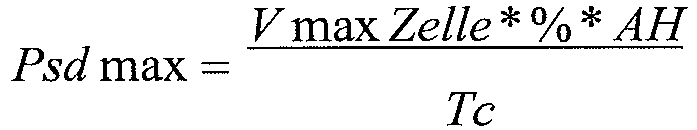 Psd max = maximale, zur Abführung optimierte Leistung, die in Watt ausgedrückt ist;Vmax Zelle = maximale Spannung, die während des Aufladens an den Klemmen einer Zelle gemessen wird und die in Volt ausgedrückt ist;% = als Prozentsatz ausgedrücktes Verhältnis, das dem maximalen Abstand zwischen zwei Zellen entspricht, der bei einem Aufladen ausgeglichen werden soll;AH = Nennkapazität der Batterie, die in Ah (Amperestunden) ausgedrückt ist;Tc = Batterieaufladezeit, die in Stunden ausgedrückt ist.
 - Verfahren nach einem der Ansprüche 2 bis 14, dadurch gekennzeichnet, dass es zu Beginn vor Einleitung der Ausführung der Aufladevorgänge darin besteht, dass die Leerlaufspannung (Vo) eines Ladegeräts (8), das an die Batterie (2) angeschlossen ist, im Hinblick auf deren Aufladung gemessen wird und dass das Aufladeverfahren gestoppt wird, mit gegebenenfalls Auslösung eines entsprechenden Alarms und/oder Anzeige einer Nachricht, wenn die Leerlaufspannung (Vo) höher als [n x maximale zulässige Spannung (Vmax) für jede Zelle (1)] ist.
- Verfahren nach einem der Ansprüche 8 bis 15, dadurch gekennzeichnet, dass es vor Ausführung einer folgenden Schleife darin besteht, dass geprüft wird, ob mindestens eine der Zellen (1) der Batterie (2) an ihren Klemmen eine Spannung aufweist, die höher als die maximale zulässige Spannung (Vmax) ist, und dass bei Bejahung das Aufladeverfahren unterbrochen wird, mit gegebenenfalls Auslösung eines entsprechenden Alarms und/oder Anzeige einer Nachricht.
- Vorrichtung zur Durchführung des Verfahrens nach einem der Ansprüche 1 bis 16, dadurch gekennzeichnet, dass sie im Wesentlichen einerseits aus einer Einheit (7) von Spannungsmessmodulen (7'), die mit jeweils einer der Zellen (1) in Reihe, die die Batterie (2) bilden, verbunden sind und die Spannungen an den Klemmen dieser messen, andererseits aus mehreren Ableitungsstromkreisen (4), die jeweils parallel an den Klemmen einer entsprechenden Zelle (1) montiert sind und die jeweils selektiv geöffnet und geschlossen sein können, und schließlich aus einer digitalen Verarbeitungseinheit (3) zur Lenkung des Verfahrens besteht, wobei die Einheit (3) Messsignale von der Einheit (7) der Spannungsmessmodule (7') empfängt und den Zustand [geschlossen/geöffnet] jedes Ableitungsstromkreises (4) steuert.
- Vorrichtung nach Anspruch 17, dadurch gekennzeichnet, dass jeder Ableitungsstromkreis (4) ein Schaltelement (5), das einen Schalter bildet und dessen Zustand von der digitalen Verarbeitungseinheit (3) gesteuert wird, und gegebenenfalls mindestens eine Stromablenkungskomponente (6), wie beispielsweise einen oder mehrere Widerstände, umfasst.
- Vorrichtung nach einem der Ansprüche 17 und 18, dadurch gekennzeichnet, dass die Einheit (7) der Spannungsmessmodule (7') einerseits n analoge Spannungsmessmodule (7'), die jeweils direkt mit einer Zelle (1) der Batterie (2) verbunden sind, andererseits einen Stromkreis-Mehrfachumschalter (9), dessen Eingänge mit den Ausgängen der Module (7') verbunden sind, und schließlich einen Stromkreis-Analog/Digital-Umsetzer (10), der am Eingang mit dem Ausgang des Stromkreis-Mehrfachumschalters (9) und am Ausgang mit der digitalen Verarbeitungseinheit zur Lenkung (3) verbunden ist, umfasst.
- Vorrichtung nach einem der Ansprüche 17 bis 19, dadurch gekennzeichnet, dass sie in eine unabhängige Elektrowerkzeugeinheit integriert ist.
Applications Claiming Priority (2)
| Application Number | Priority Date | Filing Date | Title |
|---|---|---|---|
| FR0500423A FR2880995B1 (fr) | 2005-01-14 | 2005-01-14 | Procede de chargement equilibre d'une batterie lithium-ion ou lithium polymere |
| PCT/FR2006/050008 WO2006075112A1 (fr) | 2005-01-14 | 2006-01-10 | Procede de chargement equilibre d'une batterie lithium-ion ou lithium polymere |
Publications (3)
| Publication Number | Publication Date |
|---|---|
| EP1854165A1 EP1854165A1 (de) | 2007-11-14 |
| EP1854165B1 EP1854165B1 (de) | 2010-03-24 |
| EP1854165B3 true EP1854165B3 (de) | 2016-06-08 |
Family
ID=34953855
Family Applications (1)
| Application Number | Title | Priority Date | Filing Date |
|---|---|---|---|
| EP06709396.3A Not-in-force EP1854165B3 (de) | 2005-01-14 | 2006-01-10 | Verfahren zum ausgewogenen aufladen einer lithiumionen- oder lithium-polymer-batterie |
Country Status (13)
| Country | Link |
|---|---|
| US (1) | US7880444B2 (de) |
| EP (1) | EP1854165B3 (de) |
| JP (1) | JP5036556B2 (de) |
| CN (1) | CN100533844C (de) |
| AT (1) | ATE462206T1 (de) |
| BR (1) | BRPI0605919B1 (de) |
| CA (1) | CA2594826C (de) |
| DE (1) | DE602006013103D1 (de) |
| DK (1) | DK1854165T3 (de) |
| ES (1) | ES2343367T7 (de) |
| FR (1) | FR2880995B1 (de) |
| RU (1) | RU2364992C2 (de) |
| WO (1) | WO2006075112A1 (de) |
Families Citing this family (38)
| Publication number | Priority date | Publication date | Assignee | Title |
|---|---|---|---|---|
| US8193778B2 (en) | 2007-07-13 | 2012-06-05 | Sanyo Electric Co., Ltd. | Method of charging a battery array |
| FR2923022B1 (fr) * | 2007-10-30 | 2010-01-08 | Peugeot Citroen Automobiles Sa | Procedes de recalage et d'estimation de l'information d'etat de charge d'une batterie et batterie correspondante |
| US8466657B2 (en) * | 2008-10-31 | 2013-06-18 | Bren-Tronics Batteries International, L.L.C. | Autonomous balancing of series connected charge storage devices |
| DE102009003873A1 (de) * | 2009-05-04 | 2010-11-18 | Paade Gmbh | Verfahren und Vorrichtung zum Aufladen von Akkumulatoren |
| US8917061B2 (en) * | 2009-09-18 | 2014-12-23 | Schneider Electric It Corporation | System and method for battery cell balancing |
| JP4928618B2 (ja) * | 2010-02-03 | 2012-05-09 | 日清紡ホールディングス株式会社 | 蓄電モジュール制御装置 |
| US8933666B2 (en) | 2010-07-12 | 2015-01-13 | The Johns Hopkins University | Device and method for continuously equalizing the charge state of lithium ion battery cells |
| RU2550817C2 (ru) * | 2010-12-21 | 2015-05-20 | Ниссан Мотор Ко., Лтд. | Система быстрой зарядки, устройство управления, способ управления количеством накопленной электрической энергии и программа |
| RU2461101C1 (ru) * | 2010-12-24 | 2012-09-10 | Открытое акционерное общество "Информационные спутниковые системы" имени академика М.Ф. Решетнёва" | Способ эксплуатации литий-ионной аккумуляторной батареи в автономной системе электропитания |
| RU2461102C1 (ru) * | 2011-04-01 | 2012-09-10 | Открытое акционерное общество "Информационные спутниковые системы" имени академика М.Ф. Решетнёва" | Способ эксплуатации литий-ионной аккумуляторной батареи в автономной системе электропитания |
| RU2486634C2 (ru) * | 2011-08-05 | 2013-06-27 | Открытое акционерное общество "Информационные спутниковые системы" имени академика М.Ф. Решетнёва" | Способ эксплуатации комплекта никель-водородных аккумуляторных батарей в системе электропитания геостационарного космического аппарата |
| RU2485638C2 (ru) * | 2011-08-05 | 2013-06-20 | Открытое акционерное общество "Информационные спутниковые системы" имени академика М.Ф. Решетнева" | Способ эксплуатации герметичной никель-водородной аккумуляторной батареи в автономной системе электропитания искусственного спутника земли |
| CN102916458B (zh) * | 2011-08-05 | 2015-06-17 | 凹凸电子(武汉)有限公司 | 电池均衡系统、电路及其方法 |
| JP6032473B2 (ja) | 2011-09-09 | 2016-11-30 | 株式会社Gsユアサ | 状態管理装置、蓄電素子の均等化方法 |
| JP6106991B2 (ja) * | 2011-09-09 | 2017-04-05 | 株式会社Gsユアサ | 状態管理装置、蓄電素子の均等化方法 |
| RU2496189C2 (ru) * | 2011-11-10 | 2013-10-20 | Открытое акционерное общество "Информационные спутниковые системы" имени академика М.Ф. Решетнева" | Способ эксплуатации литий-ионной аккумуляторной батареи |
| TWM484846U (zh) * | 2012-03-29 | 2014-08-21 | Bmtpow Shenzhen Ltd | 鋰電池組主動電荷均衡系統 |
| EP2665120B1 (de) | 2012-05-14 | 2016-08-03 | Micro-Beam SA | Verfahren und System zum Ausgleich von Zellen, die Bestandteil einer Batterie sind |
| WO2013181121A1 (en) * | 2012-05-30 | 2013-12-05 | Axion Power International, Inc. | Equalization of string battery configuration |
| FR2993417B1 (fr) | 2012-07-10 | 2014-07-18 | Batscap Sa | Procede de charge d'une batterie et batterie ainsi chargee |
| CN104701899A (zh) * | 2013-12-04 | 2015-06-10 | 哈尔滨智木科技有限公司 | 一种电池均衡管理方法及均衡装置 |
| CN104124480B (zh) * | 2014-07-18 | 2017-04-05 | 刘仲尧 | 一种平衡电芯电压的方法和系统 |
| FR3024299B1 (fr) * | 2014-07-23 | 2016-09-09 | Electricite De France | Pilotage de charge d'une batterie metal-air |
| JP6821584B2 (ja) * | 2015-10-30 | 2021-01-27 | 三洋電機株式会社 | 蓄電システム |
| RU2638825C2 (ru) * | 2015-11-06 | 2017-12-18 | Акционерное общество "Информационные спутниковые системы" имени академика М.Ф. Решетнёва" | Способ эксплуатации литий-ионной аккумуляторной батареи в составе автономной системы электропитания искусственного спутника Земли |
| RU2647128C2 (ru) * | 2015-12-04 | 2018-03-14 | Российская Федерация, от имени которой выступает Министерство обороны Российской Федерации | Способ заряда литий-ионной аккумуляторной батареи |
| RU2610147C1 (ru) * | 2015-12-08 | 2017-02-08 | федеральное государственное бюджетное образовательное учреждение высшего образования "Южно-Российский государственный политехнический университет (НПИ) имени М.И. Платова" | Способ автоматического контроля технического состояния элементов смешанной (последовательное соединение групп параллельных элементов) аккумуляторной батареи и устройство для его осуществления |
| RU2610897C1 (ru) * | 2015-12-08 | 2017-02-17 | федеральное государственное бюджетное образовательное учреждение высшего образования "Южно-Российский государственный политехнический университет (НПИ) имени М.И. Платова" | Способ автоматического контроля технического состояния элементов смешанной (параллельное соединение групп последовательных элементов) аккумуляторной батареи и устройство для его осуществления |
| US9850161B2 (en) | 2016-03-29 | 2017-12-26 | Applied Materials, Inc. | Fluoride glazes from fluorine ion treatment |
| RU2637815C2 (ru) * | 2016-04-11 | 2017-12-07 | Российская Федерация, от имени которой выступает Государственная корпорация по космической деятельности "РОСКОСМОС" | Способ эксплуатации литий-ионной аккумуляторной батареи в составе автономной системы электропитания искусственного спутника Земли |
| CN107332292B (zh) | 2016-04-29 | 2021-02-26 | 华为技术有限公司 | 一种电压采集电路及电路控制方法 |
| CN106558899B (zh) * | 2017-01-04 | 2019-12-06 | 上海广为美线电源电器有限公司 | 电池组平衡修复管理系统 |
| JP2018117438A (ja) * | 2017-01-17 | 2018-07-26 | 太陽誘電株式会社 | リチウムイオンキャパシタを備えた電源モジュール |
| CN106848451B (zh) * | 2017-02-20 | 2019-03-19 | 成都雅骏新能源汽车科技股份有限公司 | 一种电池压差自适应调节方法 |
| CN108512280B (zh) * | 2018-05-04 | 2023-06-30 | 厦门芯阳科技股份有限公司 | 一种串联电池组均衡充电控制方法 |
| CN109037814B (zh) * | 2018-09-05 | 2021-02-19 | 成都芯源系统有限公司 | 一种充电平衡管理电路和方法 |
| RU2699051C1 (ru) * | 2018-09-24 | 2019-09-03 | Акционерное общество "Информационные спутниковые системы" имени академика М.Ф. Решетнёва" | Способ эксплуатации литий-ионной аккумуляторной батареи в автономной системе электропитания |
| RU2747530C1 (ru) * | 2020-10-14 | 2021-05-06 | Общество с ограниченной ответственностью "Литэко" | Способ управления системой балансировки литий-ионной аккумуляторной батареи |
Family Cites Families (14)
| Publication number | Priority date | Publication date | Assignee | Title |
|---|---|---|---|---|
| JPH08213055A (ja) * | 1995-02-08 | 1996-08-20 | Honda Motor Co Ltd | 組電池の充電方法及びその装置 |
| US5773159A (en) * | 1995-07-18 | 1998-06-30 | Beard; Paul | Multicell configuration for lithium cells or the like |
| US5773959A (en) * | 1996-01-11 | 1998-06-30 | Lockheed Martin Corporation | Lithium polymer battery charger methods and apparatus |
| JP3503453B2 (ja) * | 1997-12-26 | 2004-03-08 | 株式会社日立製作所 | 電池システム及びそれを用いた電気自動車 |
| JP3870577B2 (ja) * | 1998-09-14 | 2007-01-17 | 株式会社デンソー | 組電池のばらつき判定方法及びバッテリ装置 |
| JP3684998B2 (ja) * | 2000-04-27 | 2005-08-17 | 新神戸電機株式会社 | 組電池の容量調整方法 |
| JP2002010505A (ja) * | 2000-06-16 | 2002-01-11 | Fuji Electric Co Ltd | 充電制御装置 |
| GB2372645B (en) * | 2001-02-22 | 2005-11-23 | Metrixx Ltd | Battery charging system |
| JP3767422B2 (ja) * | 2001-06-01 | 2006-04-19 | 日産自動車株式会社 | 充電方法および充電装置 |
| DE10203909C1 (de) * | 2002-01-31 | 2003-11-20 | Dialog Semiconductor Gmbh | Lade/Entlade-Schutzschaltung für eine wiederaufladbare Batterie |
| US6700350B2 (en) * | 2002-05-30 | 2004-03-02 | Texas Instruments Incorporated | Method and apparatus for controlling charge balance among cells while charging a battery array |
| US7081737B2 (en) * | 2003-06-19 | 2006-07-25 | O2Micro International Limited | Battery cell monitoring and balancing circuit |
| US7126312B2 (en) * | 2004-07-28 | 2006-10-24 | Enerdel, Inc. | Method and apparatus for balancing multi-cell lithium battery systems |
| US7417405B2 (en) * | 2004-10-04 | 2008-08-26 | Black & Decker Inc. | Battery monitoring arrangement having an integrated circuit with logic controller in a battery pack |
-
2005
- 2005-01-14 FR FR0500423A patent/FR2880995B1/fr not_active Expired - Fee Related
-
2006
- 2006-01-10 AT AT06709396T patent/ATE462206T1/de active
- 2006-01-10 WO PCT/FR2006/050008 patent/WO2006075112A1/fr active Application Filing
- 2006-01-10 DE DE602006013103T patent/DE602006013103D1/de active Active
- 2006-01-10 US US11/795,263 patent/US7880444B2/en not_active Expired - Fee Related
- 2006-01-10 BR BRPI0605919A patent/BRPI0605919B1/pt not_active IP Right Cessation
- 2006-01-10 CN CNB2006800022305A patent/CN100533844C/zh not_active Expired - Fee Related
- 2006-01-10 JP JP2007550819A patent/JP5036556B2/ja not_active Expired - Fee Related
- 2006-01-10 CA CA2594826A patent/CA2594826C/fr not_active Expired - Fee Related
- 2006-01-10 DK DK06709396.3T patent/DK1854165T3/da active
- 2006-01-10 RU RU2007130852/09A patent/RU2364992C2/ru not_active IP Right Cessation
- 2006-01-10 ES ES06709396.3T patent/ES2343367T7/es active Active
- 2006-01-10 EP EP06709396.3A patent/EP1854165B3/de not_active Not-in-force
Also Published As
| Publication number | Publication date |
|---|---|
| EP1854165A1 (de) | 2007-11-14 |
| RU2007130852A (ru) | 2009-02-20 |
| BRPI0605919B1 (pt) | 2017-01-31 |
| CN100533844C (zh) | 2009-08-26 |
| FR2880995A1 (fr) | 2006-07-21 |
| DE602006013103D1 (de) | 2010-05-06 |
| RU2364992C2 (ru) | 2009-08-20 |
| FR2880995B1 (fr) | 2007-04-06 |
| JP2008527963A (ja) | 2008-07-24 |
| WO2006075112A1 (fr) | 2006-07-20 |
| ES2343367T3 (es) | 2010-07-29 |
| DK1854165T3 (da) | 2010-07-19 |
| ATE462206T1 (de) | 2010-04-15 |
| CA2594826A1 (fr) | 2006-07-20 |
| BRPI0605919A2 (pt) | 2009-05-26 |
| ES2343367T7 (es) | 2016-11-22 |
| CA2594826C (fr) | 2013-09-03 |
| US20080197805A1 (en) | 2008-08-21 |
| JP5036556B2 (ja) | 2012-09-26 |
| US7880444B2 (en) | 2011-02-01 |
| EP1854165B1 (de) | 2010-03-24 |
| CN101103487A (zh) | 2008-01-09 |
Similar Documents
| Publication | Publication Date | Title |
|---|---|---|
| EP1854165B3 (de) | Verfahren zum ausgewogenen aufladen einer lithiumionen- oder lithium-polymer-batterie | |
| EP1685622B3 (de) | Gleichgewichts-ladeverfahren für eine lithiumionen- oder lithiumpolymerbatterie | |
| EP1774353B1 (de) | Verfahren zur akkuspeicherverwaltung | |
| EP0216662B1 (de) | Anordnung zur Überwachung einer Akkumulatorenbatterie | |
| EP2397863B1 (de) | Verfahren zur Überwachung des Zustands einer Batterie | |
| EP2164152B1 (de) | Pulsierendes Aufladeverfahren einer Batterie in einem autonomen System, das einen Superkondensator umfasst | |
| EP2600462B1 (de) | Verfahren zum Ausgleich von Spannungen elektrischer Elemente, die auf mehreren parallelen Zweigen angeordnet sind | |
| EP1265336A2 (de) | Ausgleichverfahren für eine elektrische Batterie im diskontinuierlichen Lade-Modus und Batterieverwaltungssystem zur Durchführung des Verfahrens | |
| EP0498715B1 (de) | Verfahren zur Ladungsoptimierung einer Akkumulatorenbatterie und Vorrichtung zu dessen Durchführung | |
| EP2309615B1 (de) | System und Verfahren zur Steuerung des Aufladevorgangs einer Batterie | |
| EP3231057B1 (de) | Verfahren und vorrichtung zur erkennung eines überladezustandes eines akkumulators einer batterie | |
| EP2079125B1 (de) | Verfahren zur Steuerung des Aufladevorgangs einer Batterie | |
| EP4189406A1 (de) | Batterieverwaltungssystem | |
| EP4134695A1 (de) | Überprüfung der messgenauigkeit eines stromzählers | |
| EP3235048B1 (de) | Gepulstes ladeverfahren für lithium-ionen batterien und apparat dafür | |
| EP0549464B1 (de) | Verfahren zur Messung des Ladezustandes eines elektrochemischen Generators | |
| EP3401647B1 (de) | Messsystem für den leistungspegel einer umweltenergiequelle | |
| FR2733093A1 (fr) | Chargeur de batterie | |
| FR2474776A1 (fr) | Appareil pour la charge d'une batterie rechargeable | |
| FR3106447A1 (fr) | Element de stockage d’energie electrique et alimentation sauvegardee associee | |
| FR2978625A1 (fr) | Methode et dispositif d'equilibrage des batteries d'accumulateurs electriques | |
| FR2746216A1 (fr) | Procede de detection de la fin de la charge d'un generateur electro-chimique |
Legal Events
| Date | Code | Title | Description |
|---|---|---|---|
| PUAI | Public reference made under article 153(3) epc to a published international application that has entered the european phase |
Free format text: ORIGINAL CODE: 0009012 |
|
| 17P | Request for examination filed |
Effective date: 20070807 |
|
| AK | Designated contracting states |
Kind code of ref document: A1 Designated state(s): AT BE BG CH CY CZ DE DK EE ES FI FR GB GR HU IE IS IT LI LT LU LV MC NL PL PT RO SE SI SK TR |
|
| DAX | Request for extension of the european patent (deleted) | ||
| GRAP | Despatch of communication of intention to grant a patent |
Free format text: ORIGINAL CODE: EPIDOSNIGR1 |
|
| RAP1 | Party data changed (applicant data changed or rights of an application transferred) |
Owner name: PELLENC (SOCIETE ANONYME) |
|
| GRAS | Grant fee paid |
Free format text: ORIGINAL CODE: EPIDOSNIGR3 |
|
| GRAA | (expected) grant |
Free format text: ORIGINAL CODE: 0009210 |
|
| AK | Designated contracting states |
Kind code of ref document: B1 Designated state(s): AT BE BG CH CY CZ DE DK EE ES FI FR GB GR HU IE IS IT LI LT LU LV MC NL PL PT RO SE SI SK TR |
|
| REG | Reference to a national code |
Ref country code: GB Ref legal event code: FG4D Free format text: NOT ENGLISH |
|
| REG | Reference to a national code |
Ref country code: CH Ref legal event code: EP |
|
| REG | Reference to a national code |
Ref country code: IE Ref legal event code: FG4D |
|
| REF | Corresponds to: |
Ref document number: 602006013103 Country of ref document: DE Date of ref document: 20100506 Kind code of ref document: P |
|
| REG | Reference to a national code |
Ref country code: CH Ref legal event code: NV Representative=s name: SCHNEIDER FELDMANN AG PATENT- UND MARKENANWAELTE |
|
| REG | Reference to a national code |
Ref country code: NL Ref legal event code: T3 |
|
| REG | Reference to a national code |
Ref country code: DK Ref legal event code: T3 |
|
| REG | Reference to a national code |
Ref country code: SE Ref legal event code: TRGR |
|
| REG | Reference to a national code |
Ref country code: GR Ref legal event code: EP Ref document number: 20100401433 Country of ref document: GR |
|
| REG | Reference to a national code |
Ref country code: ES Ref legal event code: FG2A Ref document number: 2343367 Country of ref document: ES Kind code of ref document: T3 |
|
| PG25 | Lapsed in a contracting state [announced via postgrant information from national office to epo] |
Ref country code: LT Free format text: LAPSE BECAUSE OF FAILURE TO SUBMIT A TRANSLATION OF THE DESCRIPTION OR TO PAY THE FEE WITHIN THE PRESCRIBED TIME-LIMIT Effective date: 20100324 |
|
| LTIE | Lt: invalidation of european patent or patent extension |
Effective date: 20100324 |
|
| PG25 | Lapsed in a contracting state [announced via postgrant information from national office to epo] |
Ref country code: SI Free format text: LAPSE BECAUSE OF FAILURE TO SUBMIT A TRANSLATION OF THE DESCRIPTION OR TO PAY THE FEE WITHIN THE PRESCRIBED TIME-LIMIT Effective date: 20100324 Ref country code: PL Free format text: LAPSE BECAUSE OF FAILURE TO SUBMIT A TRANSLATION OF THE DESCRIPTION OR TO PAY THE FEE WITHIN THE PRESCRIBED TIME-LIMIT Effective date: 20100324 Ref country code: LV Free format text: LAPSE BECAUSE OF FAILURE TO SUBMIT A TRANSLATION OF THE DESCRIPTION OR TO PAY THE FEE WITHIN THE PRESCRIBED TIME-LIMIT Effective date: 20100324 |
|
| REG | Reference to a national code |
Ref country code: SK Ref legal event code: T3 Ref document number: E 7607 Country of ref document: SK |
|
| REG | Reference to a national code |
Ref country code: IE Ref legal event code: FD4D |
|
| PG25 | Lapsed in a contracting state [announced via postgrant information from national office to epo] |
Ref country code: RO Free format text: LAPSE BECAUSE OF FAILURE TO SUBMIT A TRANSLATION OF THE DESCRIPTION OR TO PAY THE FEE WITHIN THE PRESCRIBED TIME-LIMIT Effective date: 20100324 Ref country code: EE Free format text: LAPSE BECAUSE OF FAILURE TO SUBMIT A TRANSLATION OF THE DESCRIPTION OR TO PAY THE FEE WITHIN THE PRESCRIBED TIME-LIMIT Effective date: 20100324 |
|
| PG25 | Lapsed in a contracting state [announced via postgrant information from national office to epo] |
Ref country code: IS Free format text: LAPSE BECAUSE OF FAILURE TO SUBMIT A TRANSLATION OF THE DESCRIPTION OR TO PAY THE FEE WITHIN THE PRESCRIBED TIME-LIMIT Effective date: 20100724 Ref country code: CZ Free format text: LAPSE BECAUSE OF FAILURE TO SUBMIT A TRANSLATION OF THE DESCRIPTION OR TO PAY THE FEE WITHIN THE PRESCRIBED TIME-LIMIT Effective date: 20100324 Ref country code: BG Free format text: LAPSE BECAUSE OF FAILURE TO SUBMIT A TRANSLATION OF THE DESCRIPTION OR TO PAY THE FEE WITHIN THE PRESCRIBED TIME-LIMIT Effective date: 20100624 |
|
| PLBE | No opposition filed within time limit |
Free format text: ORIGINAL CODE: 0009261 |
|
| PG25 | Lapsed in a contracting state [announced via postgrant information from national office to epo] |
Ref country code: PT Free format text: LAPSE BECAUSE OF FAILURE TO SUBMIT A TRANSLATION OF THE DESCRIPTION OR TO PAY THE FEE WITHIN THE PRESCRIBED TIME-LIMIT Effective date: 20100726 Ref country code: IE Free format text: LAPSE BECAUSE OF FAILURE TO SUBMIT A TRANSLATION OF THE DESCRIPTION OR TO PAY THE FEE WITHIN THE PRESCRIBED TIME-LIMIT Effective date: 20100324 |
|
| 26N | No opposition filed |
Effective date: 20101228 |
|
| PGFP | Annual fee paid to national office [announced via postgrant information from national office to epo] |
Ref country code: LU Payment date: 20110207 Year of fee payment: 6 |
|
| PGFP | Annual fee paid to national office [announced via postgrant information from national office to epo] |
Ref country code: GR Payment date: 20110127 Year of fee payment: 6 |
|
| PGFP | Annual fee paid to national office [announced via postgrant information from national office to epo] |
Ref country code: MC Payment date: 20120123 Year of fee payment: 7 |
|
| PG25 | Lapsed in a contracting state [announced via postgrant information from national office to epo] |
Ref country code: CY Free format text: LAPSE BECAUSE OF FAILURE TO SUBMIT A TRANSLATION OF THE DESCRIPTION OR TO PAY THE FEE WITHIN THE PRESCRIBED TIME-LIMIT Effective date: 20100324 |
|
| PG25 | Lapsed in a contracting state [announced via postgrant information from national office to epo] |
Ref country code: MC Free format text: LAPSE BECAUSE OF NON-PAYMENT OF DUE FEES Effective date: 20130131 |
|
| REG | Reference to a national code |
Ref country code: GR Ref legal event code: ML Ref document number: 20100401433 Country of ref document: GR Effective date: 20130802 |
|
| PG25 | Lapsed in a contracting state [announced via postgrant information from national office to epo] |
Ref country code: HU Free format text: LAPSE BECAUSE OF FAILURE TO SUBMIT A TRANSLATION OF THE DESCRIPTION OR TO PAY THE FEE WITHIN THE PRESCRIBED TIME-LIMIT Effective date: 20100324 Ref country code: GR Free format text: LAPSE BECAUSE OF NON-PAYMENT OF DUE FEES Effective date: 20130802 |
|
| PGFP | Annual fee paid to national office [announced via postgrant information from national office to epo] |
Ref country code: SK Payment date: 20140110 Year of fee payment: 9 |
|
| PGFP | Annual fee paid to national office [announced via postgrant information from national office to epo] |
Ref country code: TR Payment date: 20140107 Year of fee payment: 9 |
|
| REG | Reference to a national code |
Ref country code: DE Ref legal event code: R055 Ref document number: 602006013103 Country of ref document: DE |
|
| PLCP | Request for limitation filed |
Free format text: ORIGINAL CODE: EPIDOSNLIM1 |
|
| PLCQ | Request for limitation of patent found admissible |
Free format text: ORIGINAL CODE: 0009231 |
|
| LIM1 | Request for limitation found admissible |
Free format text: SEQUENCE NO: 1; FILED AFTER OPPOSITION PERIOD Filing date: 20150319 Effective date: 20150319 |
|
| TPAC | Observations filed by third parties |
Free format text: ORIGINAL CODE: EPIDOSNTIPA |
|
| PG25 | Lapsed in a contracting state [announced via postgrant information from national office to epo] |
Ref country code: LU Free format text: LAPSE BECAUSE OF NON-PAYMENT OF DUE FEES Effective date: 20130110 |
|
| PLBY | Limitation procedure: information modified related to despatch of communication from examining division + time limit |
Free format text: ORIGINAL CODE: EPIDOSCLIR2 |
|
| REG | Reference to a national code |
Ref country code: SK Ref legal event code: MM4A Ref document number: E 7607 Country of ref document: SK Effective date: 20150110 |
|
| PLCO | Limitation procedure: reply received to communication from examining division + time limit |
Free format text: ORIGINAL CODE: EPIDOSNLIR3 |
|
| PG25 | Lapsed in a contracting state [announced via postgrant information from national office to epo] |
Ref country code: SK Free format text: LAPSE BECAUSE OF NON-PAYMENT OF DUE FEES Effective date: 20150110 |
|
| REG | Reference to a national code |
Ref country code: FR Ref legal event code: PLFP Year of fee payment: 11 |
|
| PLCO | Limitation procedure: reply received to communication from examining division + time limit |
Free format text: ORIGINAL CODE: EPIDOSNLIR3 |
|
| PLCR | Communication despatched that request for limitation of patent was allowed |
Free format text: ORIGINAL CODE: 0009245 |
|
| REG | Reference to a national code |
Ref country code: DE Ref legal event code: R097 Ref document number: 602006013103 Country of ref document: DE Ref country code: DE Ref legal event code: R056 Ref document number: 602006013103 Country of ref document: DE |
|
| PGFP | Annual fee paid to national office [announced via postgrant information from national office to epo] |
Ref country code: NL Payment date: 20151229 Year of fee payment: 11 |
|
| PGFP | Annual fee paid to national office [announced via postgrant information from national office to epo] |
Ref country code: DK Payment date: 20160105 Year of fee payment: 11 |
|
| PLCN | Payment of fee for limitation of patent |
Free format text: ORIGINAL CODE: EPIDOSNRAL3 |
|
| PUAM | (expected) publication of b3 document |
Free format text: ORIGINAL CODE: 0009410 |
|
| STAA | Information on the status of an ep patent application or granted ep patent |
Free format text: STATUS: THE PATENT HAS BEEN LIMITED |
|
| PGFP | Annual fee paid to national office [announced via postgrant information from national office to epo] |
Ref country code: AT Payment date: 20160121 Year of fee payment: 11 Ref country code: FI Payment date: 20160118 Year of fee payment: 11 |
|
| REG | Reference to a national code |
Ref country code: CH Ref legal event code: AELM |
|
| REG | Reference to a national code |
Ref country code: SE Ref legal event code: REB3 Effective date: 20160608 |
|
| REG | Reference to a national code |
Ref country code: NL Ref legal event code: MP Effective date: 20100324 |
|
| PG25 | Lapsed in a contracting state [announced via postgrant information from national office to epo] |
Ref country code: FI Free format text: LAPSE BECAUSE OF FAILURE TO SUBMIT A TRANSLATION OF THE DESCRIPTION OR TO PAY THE FEE WITHIN THE PRESCRIBED TIME-LIMIT Effective date: 20160608 |
|
| PG25 | Lapsed in a contracting state [announced via postgrant information from national office to epo] |
Ref country code: NL Free format text: LAPSE BECAUSE OF FAILURE TO SUBMIT A TRANSLATION OF THE DESCRIPTION OR TO PAY THE FEE WITHIN THE PRESCRIBED TIME-LIMIT Effective date: 20100324 |
|
| REG | Reference to a national code |
Ref country code: FR Ref legal event code: PLFP Year of fee payment: 12 |
|
| PG25 | Lapsed in a contracting state [announced via postgrant information from national office to epo] |
Ref country code: TR Free format text: LAPSE BECAUSE OF NON-PAYMENT OF DUE FEES Effective date: 20150110 |
|
| REG | Reference to a national code |
Ref country code: AT Ref legal event code: MM01 Ref document number: 462206 Country of ref document: AT Kind code of ref document: T Effective date: 20170110 |
|
| PG25 | Lapsed in a contracting state [announced via postgrant information from national office to epo] |
Ref country code: AT Free format text: LAPSE BECAUSE OF NON-PAYMENT OF DUE FEES Effective date: 20170110 |
|
| REG | Reference to a national code |
Ref country code: FR Ref legal event code: PLFP Year of fee payment: 13 |
|
| PG25 | Lapsed in a contracting state [announced via postgrant information from national office to epo] |
Ref country code: DK Free format text: LAPSE BECAUSE OF FAILURE TO SUBMIT A TRANSLATION OF THE DESCRIPTION OR TO PAY THE FEE WITHIN THE PRESCRIBED TIME-LIMIT Effective date: 20160608 |
|
| PG25 | Lapsed in a contracting state [announced via postgrant information from national office to epo] |
Ref country code: NL Free format text: LAPSE BECAUSE OF NON-PAYMENT OF DUE FEES Effective date: 20100324 |
|
| PGFP | Annual fee paid to national office [announced via postgrant information from national office to epo] |
Ref country code: GB Payment date: 20200110 Year of fee payment: 15 Ref country code: SE Payment date: 20200116 Year of fee payment: 15 |
|
| PGFP | Annual fee paid to national office [announced via postgrant information from national office to epo] |
Ref country code: BE Payment date: 20200115 Year of fee payment: 15 |
|
| REG | Reference to a national code |
Ref country code: CH Ref legal event code: PFA Owner name: PELLENC (SOCIETE ANONYME), FR Free format text: FORMER OWNER: PELLENC (SOCIETE ANONYME), FR |
|
| PGFP | Annual fee paid to national office [announced via postgrant information from national office to epo] |
Ref country code: IT Payment date: 20210121 Year of fee payment: 16 Ref country code: CH Payment date: 20210120 Year of fee payment: 16 Ref country code: FR Payment date: 20210121 Year of fee payment: 16 |
|
| PGFP | Annual fee paid to national office [announced via postgrant information from national office to epo] |
Ref country code: ES Payment date: 20210326 Year of fee payment: 16 Ref country code: DE Payment date: 20210120 Year of fee payment: 16 |
|
| REG | Reference to a national code |
Ref country code: SE Ref legal event code: EUG |
|
| GBPC | Gb: european patent ceased through non-payment of renewal fee |
Effective date: 20210110 |
|
| REG | Reference to a national code |
Ref country code: BE Ref legal event code: MM Effective date: 20210131 |
|
| PG25 | Lapsed in a contracting state [announced via postgrant information from national office to epo] |
Ref country code: SE Free format text: LAPSE BECAUSE OF NON-PAYMENT OF DUE FEES Effective date: 20210111 Ref country code: GB Free format text: LAPSE BECAUSE OF NON-PAYMENT OF DUE FEES Effective date: 20210110 |
|
| PG25 | Lapsed in a contracting state [announced via postgrant information from national office to epo] |
Ref country code: BE Free format text: LAPSE BECAUSE OF NON-PAYMENT OF DUE FEES Effective date: 20210131 |
|
| REG | Reference to a national code |
Ref country code: DE Ref legal event code: R119 Ref document number: 602006013103 Country of ref document: DE |
|
| REG | Reference to a national code |
Ref country code: CH Ref legal event code: PL |
|
| PG25 | Lapsed in a contracting state [announced via postgrant information from national office to epo] |
Ref country code: DE Free format text: LAPSE BECAUSE OF NON-PAYMENT OF DUE FEES Effective date: 20220802 |
|
| PG25 | Lapsed in a contracting state [announced via postgrant information from national office to epo] |
Ref country code: FR Free format text: LAPSE BECAUSE OF NON-PAYMENT OF DUE FEES Effective date: 20220131 |
|
| PG25 | Lapsed in a contracting state [announced via postgrant information from national office to epo] |
Ref country code: LI Free format text: LAPSE BECAUSE OF NON-PAYMENT OF DUE FEES Effective date: 20220131 Ref country code: CH Free format text: LAPSE BECAUSE OF NON-PAYMENT OF DUE FEES Effective date: 20220131 |
|
| PG25 | Lapsed in a contracting state [announced via postgrant information from national office to epo] |
Ref country code: IT Free format text: LAPSE BECAUSE OF NON-PAYMENT OF DUE FEES Effective date: 20220110 |
|
| REG | Reference to a national code |
Ref country code: ES Ref legal event code: FD2A Effective date: 20230224 |
|
| PG25 | Lapsed in a contracting state [announced via postgrant information from national office to epo] |
Ref country code: ES Free format text: LAPSE BECAUSE OF NON-PAYMENT OF DUE FEES Effective date: 20220111 |