EP1852574A2 - Betriebsmethode für ein Ölsystems einer Gasturbine - Google Patents
Betriebsmethode für ein Ölsystems einer Gasturbine Download PDFInfo
- Publication number
- EP1852574A2 EP1852574A2 EP07251824A EP07251824A EP1852574A2 EP 1852574 A2 EP1852574 A2 EP 1852574A2 EP 07251824 A EP07251824 A EP 07251824A EP 07251824 A EP07251824 A EP 07251824A EP 1852574 A2 EP1852574 A2 EP 1852574A2
- Authority
- EP
- European Patent Office
- Prior art keywords
- oil
- engine
- electric machine
- generator
- electric
- Prior art date
- Legal status (The legal status is an assumption and is not a legal conclusion. Google has not performed a legal analysis and makes no representation as to the accuracy of the status listed.)
- Withdrawn
Links
- 238000000034 method Methods 0.000 title claims abstract description 31
- 239000010705 motor oil Substances 0.000 title description 4
- 238000005086 pumping Methods 0.000 claims abstract description 8
- 239000002826 coolant Substances 0.000 claims abstract description 7
- 238000001816 cooling Methods 0.000 claims description 9
- 239000007858 starting material Substances 0.000 claims description 2
- 239000003921 oil Substances 0.000 description 49
- 239000007789 gas Substances 0.000 description 10
- 239000003570 air Substances 0.000 description 5
- 238000010586 diagram Methods 0.000 description 3
- 239000000567 combustion gas Substances 0.000 description 2
- 239000000446 fuel Substances 0.000 description 2
- 238000012986 modification Methods 0.000 description 2
- 230000004048 modification Effects 0.000 description 2
- 239000012080 ambient air Substances 0.000 description 1
- 238000004891 communication Methods 0.000 description 1
- 230000000694 effects Effects 0.000 description 1
- 230000005611 electricity Effects 0.000 description 1
- 230000010006 flight Effects 0.000 description 1
- 230000001050 lubricating effect Effects 0.000 description 1
- 238000013021 overheating Methods 0.000 description 1
- 238000012552 review Methods 0.000 description 1
- 238000007789 sealing Methods 0.000 description 1
- 230000007704 transition Effects 0.000 description 1
Images
Classifications
-
- F—MECHANICAL ENGINEERING; LIGHTING; HEATING; WEAPONS; BLASTING
- F01—MACHINES OR ENGINES IN GENERAL; ENGINE PLANTS IN GENERAL; STEAM ENGINES
- F01D—NON-POSITIVE DISPLACEMENT MACHINES OR ENGINES, e.g. STEAM TURBINES
- F01D19/00—Starting of machines or engines; Regulating, controlling, or safety means in connection therewith
-
- F—MECHANICAL ENGINEERING; LIGHTING; HEATING; WEAPONS; BLASTING
- F01—MACHINES OR ENGINES IN GENERAL; ENGINE PLANTS IN GENERAL; STEAM ENGINES
- F01D—NON-POSITIVE DISPLACEMENT MACHINES OR ENGINES, e.g. STEAM TURBINES
- F01D25/00—Component parts, details, or accessories, not provided for in, or of interest apart from, other groups
- F01D25/08—Cooling; Heating; Heat-insulation
- F01D25/12—Cooling
- F01D25/125—Cooling of bearings
-
- F—MECHANICAL ENGINEERING; LIGHTING; HEATING; WEAPONS; BLASTING
- F01—MACHINES OR ENGINES IN GENERAL; ENGINE PLANTS IN GENERAL; STEAM ENGINES
- F01D—NON-POSITIVE DISPLACEMENT MACHINES OR ENGINES, e.g. STEAM TURBINES
- F01D25/00—Component parts, details, or accessories, not provided for in, or of interest apart from, other groups
- F01D25/18—Lubricating arrangements
- F01D25/20—Lubricating arrangements using lubrication pumps
-
- F—MECHANICAL ENGINEERING; LIGHTING; HEATING; WEAPONS; BLASTING
- F02—COMBUSTION ENGINES; HOT-GAS OR COMBUSTION-PRODUCT ENGINE PLANTS
- F02C—GAS-TURBINE PLANTS; AIR INTAKES FOR JET-PROPULSION PLANTS; CONTROLLING FUEL SUPPLY IN AIR-BREATHING JET-PROPULSION PLANTS
- F02C7/00—Features, components parts, details or accessories, not provided for in, or of interest apart form groups F02C1/00 - F02C6/00; Air intakes for jet-propulsion plants
- F02C7/26—Starting; Ignition
- F02C7/268—Starting drives for the rotor, acting directly on the rotor of the gas turbine to be started
- F02C7/275—Mechanical drives
-
- F—MECHANICAL ENGINEERING; LIGHTING; HEATING; WEAPONS; BLASTING
- F05—INDEXING SCHEMES RELATING TO ENGINES OR PUMPS IN VARIOUS SUBCLASSES OF CLASSES F01-F04
- F05D—INDEXING SCHEME FOR ASPECTS RELATING TO NON-POSITIVE-DISPLACEMENT MACHINES OR ENGINES, GAS-TURBINES OR JET-PROPULSION PLANTS
- F05D2260/00—Function
- F05D2260/20—Heat transfer, e.g. cooling
- F05D2260/205—Cooling fluid recirculation, i.e. after cooling one or more components is the cooling fluid recovered and used elsewhere for other purposes
-
- F—MECHANICAL ENGINEERING; LIGHTING; HEATING; WEAPONS; BLASTING
- F05—INDEXING SCHEMES RELATING TO ENGINES OR PUMPS IN VARIOUS SUBCLASSES OF CLASSES F01-F04
- F05D—INDEXING SCHEME FOR ASPECTS RELATING TO NON-POSITIVE-DISPLACEMENT MACHINES OR ENGINES, GAS-TURBINES OR JET-PROPULSION PLANTS
- F05D2260/00—Function
- F05D2260/85—Starting
-
- F—MECHANICAL ENGINEERING; LIGHTING; HEATING; WEAPONS; BLASTING
- F05—INDEXING SCHEMES RELATING TO ENGINES OR PUMPS IN VARIOUS SUBCLASSES OF CLASSES F01-F04
- F05D—INDEXING SCHEME FOR ASPECTS RELATING TO NON-POSITIVE-DISPLACEMENT MACHINES OR ENGINES, GAS-TURBINES OR JET-PROPULSION PLANTS
- F05D2260/00—Function
- F05D2260/90—Braking
-
- Y—GENERAL TAGGING OF NEW TECHNOLOGICAL DEVELOPMENTS; GENERAL TAGGING OF CROSS-SECTIONAL TECHNOLOGIES SPANNING OVER SEVERAL SECTIONS OF THE IPC; TECHNICAL SUBJECTS COVERED BY FORMER USPC CROSS-REFERENCE ART COLLECTIONS [XRACs] AND DIGESTS
- Y02—TECHNOLOGIES OR APPLICATIONS FOR MITIGATION OR ADAPTATION AGAINST CLIMATE CHANGE
- Y02T—CLIMATE CHANGE MITIGATION TECHNOLOGIES RELATED TO TRANSPORTATION
- Y02T50/00—Aeronautics or air transport
- Y02T50/60—Efficient propulsion technologies, e.g. for aircraft
Definitions
- the invention relates to gas turbine engines, in more particularly to a method for lubricating a gas turbine engine.
- a gas turbine engine comprises a plurality of rotating elements, such as shafts, rotating at a very high rotation speed when the engine is running. These rotating elements are supported by bearings provided at various strategic locations in the engine. These bearings are lubricated using pressurized oil. Oil is sent to the bearing cavities using oil pumps that are mechanically driven and as a result will start to pump oil to the bearings as soon as the engine starter is engaged.
- One drawback is that when starting the engine or during the run down, the air-oil seals of bearing cavities are inefficient because of the lack of sufficient air pressure. This may result in oil leaks, which is undesirable.
- the present invention provides a method of operating a gas turbine engine having a combustor and at least one turbine shaft drivingly connected to an electric machine, the engine also having an oil system communicating with an electric oil pump, at least one bearing cavity of the engine and a coolant passage of the electric machine, the method comprising: rotating the shaft while the combustor is unlit; controlling the oil pump to intermittently provide oil flow to the oil system for cooling the electric machine.
- the present invention provides a method of operating a gas turbine engine having a motor/generator drivingly connected to a turbine shaft, the engine having an oil system communicating with an electric oil pump, at least one bearing cavity of the engine and a coolant passage of the motor/generator, the method comprising: rotating the shaft with the motor/generator; pumping oil to provide an intermittent oil flow to the oil system; providing pumped oil to the motor/generator for cooling; lighting the engine; and then pumping oil to provide a continuous oil flow to the oil system.
- the present invention provides a method of operating a gas turbine engine having a combustor and at least one electric machine, the engine having an oil system communicating with an electric oil pump, at least one bearing cavity of the engine and a coolant passage of the electric machine, the method comprising the step of pumping oil intermittently to the oil system to cool the electric machine.
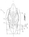
- FIG. 1 schematically illustrates an example of a gas turbine engine 10 of a type preferably provided for use in subsonic flights.
- the engine 10 generally comprises in serial flow communication a fan 12 through which ambient air is propelled, a multi-stage compressor 14 for pressurizing the air, a combustor 16 in which the compressed air is mixed with fuel and ignited for generating a stream of hot combustion gases, and a turbine section 18 for extracting energy from the combustion gases.
- the engine 10 also includes an embedded or integral starter-generator 20 which is oil-cooled and thus communicated with an oil supply 22 via and engine oil system (not shown).
- the engine oil system also communicates with a plurality of engine bearing cavities which house the main engine bearing (not shown), and includes at least one oil pump 24.
- Operation of the starter-generator 20 is controlled by a controller 26 to, in one mode, start the gas turbine engine, and in another mode, generate electricity for powering electrical systems, such as electric fuel pumps, electric oil pump 24, and other engine and aircraft services. Controller 26 also controls at least electric oil pump 24. The controller 26 communicates with a power source 28, such as a battery or auxiliary power unit, to provide power during starting.
- a power source 28 such as a battery or auxiliary power unit
- starter-generator 20 In start-up, electrical power from power source 28 is provided by controller 26 to drive starter-generator 20. As starter-generator 20 operates, the machine tends to heat up, and therefore it is desirable, to circulate cooling oil to the starter-generator 20. For economy of weight and complexity, preferably the oil used for cooling starter-generator 20 is obtained from the general oil system of the engine. However, in order to alleviate the problem of bearing cavity flooding if the engine oil system were fully powered up during starting, the present invention instead provides intermittent oil flow pulses, sufficient to cool the starter-generator 20 and yet insufficient to undesirably flood the bearing cavities, at least until such time as the air pressure in bearing cavities is sufficient to seal them.
- the controller 26 which can be for example the electronic engine control (EEC)
- EEC electronic engine control
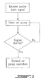
- the controller 26 can be provided with software instructions to command the electric oil pump 24 to intermittently pulse the oil supply during engine start, as mentioned the pulsing large enough to permit extended motoring of the engine without overheating the starter-generator 20, and yet small enough to prevent bearing cavity flooding.
- the oil pump can be operated intermittently for a short period of time, thus providing short, limited burst of oil in order to lower the initial oil flow to the bearing cavities. Normal operation of the oil pump may then begin after the start-up, either instantly or progressively (i.e. the length and/or strength of the intermittent bursts can gradually be extended to transition to normal operation).
- Maximum oil flow is not required, and in fact is not desired, for the bearings until the engine compressor reaches sufficient pressure to provide bearing cavity sealing air pressure.
- pulsing the pump operation can provide intermittent oil pressure for cooling, without flooding the bearing cavities.
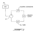
- FIGS 2 and 3 schematically illustrate possible examples of arrangement for performing the method. It should be noted that these figures are schematic in nature since other elements would be provided in a complete system, such as an oil cooler, a strainer, etc.
- Figure 2 shows the EEC 26 that is electrically connected to the oil pump 24 providing oil to starter-generator 20, at least one bearing cavity 30 and an oil tank 22.
- Figure 3 shows a block diagram according to the described method.
- the present invention provides a way to supply oil to portions of the engine during start-up and yet provide means to prevent bearing flooding without completely interrupting the supply of oil to the bearings or any other location.
Landscapes
- Engineering & Computer Science (AREA)
- Mechanical Engineering (AREA)
- General Engineering & Computer Science (AREA)
- Chemical & Material Sciences (AREA)
- Combustion & Propulsion (AREA)
- Motor Or Generator Cooling System (AREA)
Applications Claiming Priority (1)
| Application Number | Priority Date | Filing Date | Title |
|---|---|---|---|
| US11/381,633 US7793505B2 (en) | 2006-05-04 | 2006-05-04 | Gas turbine engine oil system operation |
Publications (1)
| Publication Number | Publication Date |
|---|---|
| EP1852574A2 true EP1852574A2 (de) | 2007-11-07 |
Family
ID=38457864
Family Applications (1)
| Application Number | Title | Priority Date | Filing Date |
|---|---|---|---|
| EP07251824A Withdrawn EP1852574A2 (de) | 2006-05-04 | 2007-05-01 | Betriebsmethode für ein Ölsystems einer Gasturbine |
Country Status (4)
| Country | Link |
|---|---|
| US (1) | US7793505B2 (de) |
| EP (1) | EP1852574A2 (de) |
| CA (1) | CA2643489C (de) |
| WO (1) | WO2007128098A1 (de) |
Cited By (4)
| Publication number | Priority date | Publication date | Assignee | Title |
|---|---|---|---|---|
| FR2914697A1 (fr) * | 2007-04-06 | 2008-10-10 | Turbomeca Sa | Dispositif d'assistance aux phases transitoires d'acceleration et de deceleration |
| FR2925110A1 (fr) * | 2007-12-13 | 2009-06-19 | Hispano Suiza Sa | Dispositif d'alimentation en huile d'un moteur d'aeronef equipe d'au moins un demarreur-generateur. |
| EP3726012A1 (de) * | 2019-04-12 | 2020-10-21 | Rolls-Royce plc | Ölpumpe für einen generator eines gasturbinentriebwerks |
| EP4286657A1 (de) * | 2022-05-31 | 2023-12-06 | Pratt & Whitney Canada Corp. | Gasturbinentriebwerk mit elektrischer maschine im kerntriebwerk |
Families Citing this family (14)
| Publication number | Priority date | Publication date | Assignee | Title |
|---|---|---|---|---|
| JP4495603B2 (ja) * | 2004-01-15 | 2010-07-07 | 株式会社日立製作所 | ガスタービン発電装置およびそれに用いる消音装置 |
| US20130091859A1 (en) * | 2011-10-17 | 2013-04-18 | Omar I. Osorio | Auxiliary power unit fluid system fluid control |
| US9024460B2 (en) * | 2012-01-04 | 2015-05-05 | General Electric Company | Waste heat recovery system generator encapsulation |
| US8984884B2 (en) | 2012-01-04 | 2015-03-24 | General Electric Company | Waste heat recovery systems |
| US9018778B2 (en) * | 2012-01-04 | 2015-04-28 | General Electric Company | Waste heat recovery system generator varnishing |
| FR2993610B1 (fr) * | 2012-07-19 | 2014-07-11 | Snecma | Refroidissement du circuit d'huile d'une turbomachine |
| FR3027061B1 (fr) * | 2014-10-10 | 2019-10-25 | Safran Helicopter Engines | Procede et dispositif de notification d'une autorisation d'arret complet d'un moteur a turbine a gaz d'aeronef |
| US10544717B2 (en) | 2016-09-07 | 2020-01-28 | Pratt & Whitney Canada Corp. | Shared oil system arrangement for an engine component and a generator |
| EP3336320B1 (de) * | 2016-12-14 | 2020-08-12 | Airbus Operations, S.L. | Ölheizungssystem für ein turbinentriebwerk zur reduzierung des anfahrmoments |
| CN109578317B (zh) * | 2018-12-29 | 2020-07-31 | 沈阳鼓风机集团自动控制系统工程有限公司 | 一种离心压缩机润滑油系统的控制方法及装置 |
| US11492969B2 (en) | 2019-12-09 | 2022-11-08 | Meggitt Aerospace Limited | Engine thermal management methods and control systems |
| GB2613246B (en) | 2021-10-15 | 2024-05-29 | Rtx Corp | Lubrication system for turbine engine electric machine |
| US12291998B2 (en) * | 2023-02-27 | 2025-05-06 | Rtx Corporation | Hybrid power system with individualized component lubrication and method for operating the same |
| US20250109709A1 (en) * | 2023-10-03 | 2025-04-03 | Rtx Corporation | Electronically driven lubrication system on gas turbine engines |
Family Cites Families (14)
| Publication number | Priority date | Publication date | Assignee | Title |
|---|---|---|---|---|
| US3769790A (en) * | 1972-03-20 | 1973-11-06 | Gen Motors Corp | Gas turbine lubrication |
| US4002224A (en) * | 1975-02-26 | 1977-01-11 | Westinghouse Electric Corporation | Turbine lubrication and emergency gas system |
| US4309870A (en) * | 1979-10-01 | 1982-01-12 | Carrier Corporation | Lubricating system for a turbomachine including a method of operating same |
| US4629033A (en) * | 1984-06-28 | 1986-12-16 | General Electric Company | Positive displacement pump utilized in lube oil system for turbomachinery |
| US5105875A (en) * | 1991-01-10 | 1992-04-21 | Sundstrand Corporation | Cooling system for auxiliary power unit |
| US5184456A (en) * | 1991-04-08 | 1993-02-09 | Avco Corporation | Gas turbine motor drive |
| GB2260577B (en) * | 1991-10-16 | 1994-10-05 | Rolls Royce Plc | Gas turbine engine starting |
| US7216473B1 (en) * | 1999-07-09 | 2007-05-15 | Hamilton Sundstrand Corporation | Turbojet engine lubrication system |
| US6886324B1 (en) * | 2002-02-15 | 2005-05-03 | The United States Of America As Represented By The Secretary Of The Army | Apparatus for reducing coking in gas turbine bearings |
| GB0218849D0 (en) * | 2002-08-14 | 2002-09-25 | Rolls Royce Plc | Lubrication system for gas turbine engine |
| GB0318400D0 (en) * | 2003-08-06 | 2003-09-10 | Rolls Royce Plc | A fluid system |
| US7373771B2 (en) * | 2004-07-09 | 2008-05-20 | Pratt & Whitney Canada Corp. | Cooling arrangement for an accessory gearbox and method of cooling |
| US7225626B2 (en) * | 2004-08-16 | 2007-06-05 | Honeywell International, Inc. | Thermal management of a gas turbine bearing compartment utilizing separate lubrication and cooling circuits |
| EP1683947A3 (de) | 2005-01-21 | 2007-04-18 | Honeywell International Inc. | Verfahren zur Steuerung des Kraftstoffstroms zur Kühlung eines Starter/Generators während des Anlassens der Machine |
-
2006
- 2006-05-04 US US11/381,633 patent/US7793505B2/en active Active
-
2007
- 2007-04-04 CA CA2643489A patent/CA2643489C/en not_active Expired - Fee Related
- 2007-04-04 WO PCT/CA2007/000555 patent/WO2007128098A1/en not_active Ceased
- 2007-05-01 EP EP07251824A patent/EP1852574A2/de not_active Withdrawn
Cited By (7)
| Publication number | Priority date | Publication date | Assignee | Title |
|---|---|---|---|---|
| FR2914697A1 (fr) * | 2007-04-06 | 2008-10-10 | Turbomeca Sa | Dispositif d'assistance aux phases transitoires d'acceleration et de deceleration |
| WO2008139096A3 (fr) * | 2007-04-06 | 2009-03-26 | Turbomeca | Turbomoteur de helicoptere comrpenant un generateur de gaz et une turbine libre |
| US8201414B2 (en) | 2007-04-06 | 2012-06-19 | Turbomeca | Assistance device for transient acceleration and deceleration phases |
| FR2925110A1 (fr) * | 2007-12-13 | 2009-06-19 | Hispano Suiza Sa | Dispositif d'alimentation en huile d'un moteur d'aeronef equipe d'au moins un demarreur-generateur. |
| EP3726012A1 (de) * | 2019-04-12 | 2020-10-21 | Rolls-Royce plc | Ölpumpe für einen generator eines gasturbinentriebwerks |
| US11421554B2 (en) | 2019-04-12 | 2022-08-23 | Rolls-Royce Plc | Gas turbine engine generator oil pump |
| EP4286657A1 (de) * | 2022-05-31 | 2023-12-06 | Pratt & Whitney Canada Corp. | Gasturbinentriebwerk mit elektrischer maschine im kerntriebwerk |
Also Published As
| Publication number | Publication date |
|---|---|
| US20070256421A1 (en) | 2007-11-08 |
| WO2007128098A1 (en) | 2007-11-15 |
| CA2643489A1 (en) | 2007-11-15 |
| US7793505B2 (en) | 2010-09-14 |
| CA2643489C (en) | 2011-11-29 |
Similar Documents
| Publication | Publication Date | Title |
|---|---|---|
| CA2643489C (en) | Gas turbine engine oil system operation | |
| EP2447507B1 (de) | Kühlanordnung für eine Turbomaschine | |
| US9121309B2 (en) | Gas turbine and method of operating a gas turbine | |
| EP1726879B1 (de) | Kraftstoffsystem mit verringertem gewicht für einen gasturbinenmotor, gasturbinenmotor mit einem derartigen krafstoffsystem und verfahren zur kraffstoffversorgung eines derartigen gasturbinenmotors | |
| CA2955506C (en) | Oil system for turbine engine and related method | |
| US8172512B2 (en) | Accessory gearbox system with compressor driven seal air supply | |
| EP2128389B1 (de) | Gasturbinenmotoranordnung | |
| RU2515912C2 (ru) | Авиационный двигатель с охлаждением электрического пускового устройства | |
| CN102562318B (zh) | 燃气涡轮发动机系统、航空器系统及其操作方法 | |
| EP3726012B1 (de) | Ölpumpe für einen generator eines gasturbinentriebwerks | |
| EP1873358A2 (de) | Vorrichtung und Verfahren zur Steuerung der Autorotation eines Gasturbinentriebwerks | |
| EP1983174A2 (de) | Vorrichtung und Verfahren zum Betreiben eines Gasturbinentriebwerks beim Hochfahren | |
| US20170321610A1 (en) | Anti-Windmilling Starter Generator | |
| EP2574759B1 (de) | Bimodaler Starter einer Turbomaschine | |
| CN114715419A (zh) | 一种辅助动力装置 | |
| US20230184129A1 (en) | Energy recovery for high power pumping systems and methods using exhaust gas heat to generate thermoelectric power | |
| CA2551904C (en) | Scavenge pump system and method | |
| RU2358120C1 (ru) | Турбовинтовой газотурбинный двигатель | |
| US12203417B2 (en) | Free turbine turbomachine comprising equipment driven by the free turbine | |
| GB2395753A (en) | Fuel compressor system for a gas turbine | |
| US20240026801A1 (en) | Rotor cooling system for shutdown | |
| JP2007092640A (ja) | ディーゼル発電設備及びその運転方法 |
Legal Events
| Date | Code | Title | Description |
|---|---|---|---|
| PUAI | Public reference made under article 153(3) epc to a published international application that has entered the european phase |
Free format text: ORIGINAL CODE: 0009012 |
|
| AK | Designated contracting states |
Kind code of ref document: A2 Designated state(s): AT BE BG CH CY CZ DE DK EE ES FI FR GB GR HU IE IS IT LI LT LU LV MC MT NL PL PT RO SE SI SK TR |
|
| AX | Request for extension of the european patent |
Extension state: AL BA HR MK YU |
|
| STAA | Information on the status of an ep patent application or granted ep patent |
Free format text: STATUS: THE APPLICATION IS DEEMED TO BE WITHDRAWN |
|
| 18D | Application deemed to be withdrawn |
Effective date: 20111201 |