EP1852286A1 - Coupling device for a roller blind and roller blind system for a vehicle roof - Google Patents
Coupling device for a roller blind and roller blind system for a vehicle roof Download PDFInfo
- Publication number
- EP1852286A1 EP1852286A1 EP06009100A EP06009100A EP1852286A1 EP 1852286 A1 EP1852286 A1 EP 1852286A1 EP 06009100 A EP06009100 A EP 06009100A EP 06009100 A EP06009100 A EP 06009100A EP 1852286 A1 EP1852286 A1 EP 1852286A1
- Authority
- EP
- European Patent Office
- Prior art keywords
- roller blind
- handle
- blinds
- latching element
- driving device
- Prior art date
- Legal status (The legal status is an assumption and is not a legal conclusion. Google has not performed a legal analysis and makes no representation as to the accuracy of the status listed.)
- Withdrawn
Links
Images


Classifications
-
- B—PERFORMING OPERATIONS; TRANSPORTING
- B60—VEHICLES IN GENERAL
- B60J—WINDOWS, WINDSCREENS, NON-FIXED ROOFS, DOORS, OR SIMILAR DEVICES FOR VEHICLES; REMOVABLE EXTERNAL PROTECTIVE COVERINGS SPECIALLY ADAPTED FOR VEHICLES
- B60J7/00—Non-fixed roofs; Roofs with movable panels, e.g. rotary sunroofs
- B60J7/0007—Non-fixed roofs; Roofs with movable panels, e.g. rotary sunroofs moveable head-liners, screens, curtains or blinds for ceilings
- B60J7/0015—Non-fixed roofs; Roofs with movable panels, e.g. rotary sunroofs moveable head-liners, screens, curtains or blinds for ceilings roller blind
Definitions
- the invention relates to a driving device for a roller blind and a roller blind system for a vehicle with a first roller blind, a second roller blind and such a driving device.
- Roller blinds with several blinds are known from the prior art and are associated with a translucent opening in the vehicle roof.
- the translucent opening may be formed by, for example, a fixed panoramic window or by one or more transparent covers of a sunroof.
- the blinds can be adjusted between an open position in which they do not obstruct the passage of light through the opening, and a closed position in which they prevent the incidence of light through the opening either completely or at least attenuate.
- the blinds can be held in different intermediate positions between the closed and the open position.
- handles which can be operated by vehicle occupants.
- the handle of the rear blinds can be arranged remotely from a vehicle driver. The driver can not take this and thus not adjust the rear roller blind.
- the object of the invention is to provide a driving device for a roller blind, by means of which several blinds are coupled together and a roller blind system for a vehicle roof that allows a plurality of roller blinds to be connected to one another.
- the invention provides a driving device for a roller blind, with a latching element and a handle, wherein the latching element is connected to the handle and can be actuated by the handle.
- the entrainment device is e.g. Part of a roller blind system consisting of two blinds and couples the blinds together so that upon actuation of the first blinds, the second roller blind is taken.
- the first roller blind is preferably the front roller blind, the handle of which can be easily actuated by a vehicle driver.
- a second, rear roller blind can be adjusted so by the driver without this must stop to operate the rear roller blind from the rear.
- the handle can thereby actuate the locking element so that the locking element assumes a position in which it acts on the rear roller blind or in which it does not attack the rear roller blind. It can e.g. be provided a resilient element which acts on the locking element in a position in which it engages the roller blind. The handle must then be operated only for decoupling the two blinds.
- the invention relates to a roller blind system for a vehicle roof, with a first roller blind, a second roller blind and a driving device of the type mentioned above, wherein the driving device can couple the blinds to each other so that when moving the first blinds, the second roller blind is taken.
- FIG. 1 schematically shows a roller blind system which can release a transparent opening of a fixed panorama window or one or more transparent covers of a sliding roof (FIG. 1a) or cover the opening completely (FIGS. 1b and 1c) or partially (FIG. 1d). This works regardless of the lid position.
- the roller blind system consists of a first, front roller blind 10 and a second, rear roller blind 12.
- the roller blinds 10, 12 are adjustable and parallel in two guide rails, not shown, which are arranged along the longitudinal side edges of the roof opening. Both blinds 10, 12 are closed in the direction of travel F by being withdrawn from the winding bodies 20, 22 to the front.
- a driving device 14 by means of which the rear roller blind 12 can be coupled to the front roller blind 10, so that when adjusting the first roller blind 10, the second shade 12 is mitver Robinson.
- FIGS. 1 to 5 the entrainment device 14 is described in a first and second embodiment, while FIGS. 6 and 7 show the entrainment device 14 in a third embodiment.
- the driving device 14 of the first and second embodiments each have a hook-like locking element 24 which can engage a bow 18 of the rear roller blind 12, wherein the bow 18 is mounted on the seen in the direction of travel F front edge of the rear roller blind 12.
- the latching element 24 is spring-loaded (spring-elastic element 26) and is acted upon by the resilient element 26 in the position in which it engages the second roller blind 12.
- a handle 28 (shown schematically in FIGS. 2 and 4) is provided, which is arranged on a bow 16 of the front roller blind 10 and is part of the driving device 14.
- the locking element 24 may be connected to the handle 28 via a cable 30 (FIGS. 2 and 3) or a linkage 32 (FIGS. 4 and 5).
- Figure 2 shows the one-piece, pre-tensioned cable 30, which connects the handle 28 with the two hook-like locking elements 24.
- the locking elements 24 are attached to the ends of the cable 30 and are acted upon by the resilient elements 26 so that they engage in recesses 36 on the bow 18 of the rear roller blind 12, wherein the recesses 36 is preferably adapted to the shape of the locking elements 24.
- There are two pulleys 34 are provided, where the rope 30 attacks.
- the front roller blind 10 can be coupled again to the rear roller blind 12 (FIGS. 1a and 1b).
- the resilient elements 26 press the locking elements 24 counter to the direction A, whereby the locking elements 24 engage in the recesses 36 and the handle 28 is pulled over the cable 30 in the starting position.
- Insertion chamfers 37 could also be provided adjacent to the recesses 36. A coupling of the second shade 12 to the first shade 10 could then take place without actuation of the handle 28, since the resilient elements 26 act on the locking elements 24 in the direction of the recesses 36, that the locking elements 24 with a suitable design of the locking elements 24 and the insertion bevels 37th get into the recesses 36.
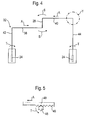
- FIGS. 4 and 5 show a second embodiment of the driving device 14.
- the entrainment device 14 is shown here as a linkage 32 with four rods 38, 40, 42, 44.
- the rods 38, 40 which are directly connected to the pivotable handle 28 (pivoting movement S) are formed as racks with a respective toothing 46.
- a toothed wheel 48 (see FIG. 5) which is provided on the rods 42, 44 can mesh in the respective toothing 46.
- the two locking elements 24 are arranged at the ends of the rods 42, 44.
- the handle 28 To couple the two blinds 10, 12 ( Figures 1a and 1b), the handle 28 must be pivoted back, causing the rods 38, 40 move counter to the direction A and the gears 48 rotate against the rotational movement T. As a result, the latching elements 24 are rotated and engage in the recesses 36.
- a coupling of the second roller blind 12 to the first roller blind 10 could also take place without actuation of the handle 28 with the aid of the resilient elements 26 and the insertion bevels 37 (shown in dashed lines in FIG Insertion bevels 37 could be provided adjacent to the recesses 36.
- FIGS. 6 and 7 show a third embodiment of the driving device 14.
- the locking element 24 and the handle 28 are provided on the front roller blind 10.
- the locking element 24 is formed like a pin and can engage in a recess 36 of a coupling rod 50.
- the coupling rod 50 is attached to the rear roller blind 10.
- the spring-loaded locking elements 24 can be pushed back against the spring force due to the insertion bevels 37 which are provided on the coupling rods 50 and then engage in the recesses 36, whereby the two blinds 10, 12 are coupled to each other.
- the handle 28 To decouple the two blinds 10, 12, the handle 28 must be pivoted (pivoting movement S). As a result, the two latching elements 24 are moved out of the recesses 36.
- the two blinds 10, 12 could also be coupled to one another via a pivoting movement of the handle 28.
- the driving device 14 of all embodiments could be part of a roller blind system whose roller blinds 10, 12 are in opposite directions.
- the winding bodies 20, 22 are arranged in the middle region of the opening, and the first roller blind 10 is pulled in the direction of travel F in order to cover the opening, and the second roller blind 12 is pulled counter to the direction of travel F in order to cover the opening.
Abstract
Description
Die Erfindung betrifft eine Mitnahmevorrichtung für ein Rollo und ein Rollosystem für ein Fahrzeug mit einem ersten Rollo, einem zweiten Rollo und einer solchen Mitnahmevorrichtung.The invention relates to a driving device for a roller blind and a roller blind system for a vehicle with a first roller blind, a second roller blind and such a driving device.
Rollosysteme mit mehreren Rollos sind aus dem Stand der Technik bekannt und sind einer lichtdurchlässigen Öffnung im Fahrzeugdach zugeordnet. Die lichtdurchlässige Öffnung kann gebildet sein durch beispielsweise ein feststehendes Panoramafenster oder durch ein bzw. mehrere transparente Deckel eines Schiebedachs. Die Rollos können zwischen einer geöffneten Stellung, in der sie den Lichtdurchtritt durch die Öffnung nicht behindern, und einer geschlossenen Stellung verstellt werden, in der sie den Lichteinfall durch die Öffnung entweder vollständig verhindern oder wenigstens abschwächen. Je nach Konstruktion können die Rollos auch in verschiedenen Zwischenstellungen zwischen der geschlossenen und der geöffneten Stellung gehalten werden.Roller blinds with several blinds are known from the prior art and are associated with a translucent opening in the vehicle roof. The translucent opening may be formed by, for example, a fixed panoramic window or by one or more transparent covers of a sunroof. The blinds can be adjusted between an open position in which they do not obstruct the passage of light through the opening, and a closed position in which they prevent the incidence of light through the opening either completely or at least attenuate. Depending on the design, the blinds can be held in different intermediate positions between the closed and the open position.
Zur Verstellung von manuell betätigten Rollos sind Griffe vorgesehen, die von Fahrzeuginsassen betätigt werden können. Bei Rollosystemen mit zwei Rollos, d.h. einem vorderen und einem hinteren Rollo, kann der Griff des hinteren Rollos entfernt von einem Fahrzeuglenker angeordnet sein. Der Fahrzeuglenker kann diesen nicht ergreifen und somit das hintere Rollo nicht verstellen.To adjust manually operated blinds handles are provided, which can be operated by vehicle occupants. In roller blind systems with two blinds, i. a front and a rear roller blind, the handle of the rear blinds can be arranged remotely from a vehicle driver. The driver can not take this and thus not adjust the rear roller blind.
Die Aufgabe der Erfindung besteht darin, eine Mitnahmevorrichtung für ein Rollo bereitzustellen, mittels derer mehrere Rollos aneinandergekoppelt werden können, und ein Rollosystem für ein Fahrzeugdach, das ein Aneinanderkoppeln mehrerer Rollos erlaubt.The object of the invention is to provide a driving device for a roller blind, by means of which several blinds are coupled together and a roller blind system for a vehicle roof that allows a plurality of roller blinds to be connected to one another.
Zu diesem Zweck sieht die Erfindung eine Mitnahmevorrichtung für ein Rollo vor, mit einem Rastelement und einem Griff, wobei das Rastelement mit dem Griff verbunden ist und von dem Griff betätigbar ist. Die Mitnahmevorrichtung ist z.B. Teil eines Rollosystems bestehend aus zwei Rollos und koppelt die Rollos so aneinander, daß bei einer Betätigung des ersten Rollos das zweite Rollo mitgenommen wird. Das erste Rollo ist dabei vorzugsweise das vordere Rollo, dessen Griff leicht von einem Fahrzeuglenker betätigt werden kann. Ein zweites, hinteres Rollo kann so vom Fahrzeuglenker mitverstellt werden, ohne daß dieser anhalten muß, um das hintere Rollo vom Fond aus zu betätigen. Der Griff kann das Rastelement dabei so betätigen, daß das Rastelement eine Stellung einnimmt, in der es an dem hinteren Rollo angreift bzw. in der es nicht am hinteren Rollo angreift. Es kann z.B. ein federelastisches Element vorgesehen sein, das das Rastelement in eine Stellung beaufschlagt, in der es an dem Rollo angreift. Der Griff muß dann nur zum Entkoppeln der beiden Rollos betätigt werden.For this purpose, the invention provides a driving device for a roller blind, with a latching element and a handle, wherein the latching element is connected to the handle and can be actuated by the handle. The entrainment device is e.g. Part of a roller blind system consisting of two blinds and couples the blinds together so that upon actuation of the first blinds, the second roller blind is taken. The first roller blind is preferably the front roller blind, the handle of which can be easily actuated by a vehicle driver. A second, rear roller blind can be adjusted so by the driver without this must stop to operate the rear roller blind from the rear. The handle can thereby actuate the locking element so that the locking element assumes a position in which it acts on the rear roller blind or in which it does not attack the rear roller blind. It can e.g. be provided a resilient element which acts on the locking element in a position in which it engages the roller blind. The handle must then be operated only for decoupling the two blinds.
Ferner betrifft die Erfindung ein Rollosystem für ein Fahrzeugdach, mit einem ersten Rollo, einem zweiten Rollo und einer Mitnahmevorrichtung der obengenannten Art, wobei die Mitnahmevorrichtung die Rollos so aneinander koppeln kann, daß bei einem Verschieben des ersten Rollos das zweite Rollo mitgenommen wird. Hinsichtlich der Vorteile wird auf die obigen Erläuterungen verwiesen.Furthermore, the invention relates to a roller blind system for a vehicle roof, with a first roller blind, a second roller blind and a driving device of the type mentioned above, wherein the driving device can couple the blinds to each other so that when moving the first blinds, the second roller blind is taken. With regard to the advantages, reference is made to the above explanations.
Weitere Merkmale und Vorteile ergeben sich aus den Unteransprüchen.Further features and advantages emerge from the subclaims.
Die Erfindung wird nachfolgend anhand von Ausführungsformen beschrieben, die in den Zeichnungen dargestellt sind. In den Zeichnungen zeigen:
- Figur 1 eine schematische, perspektivische Ansicht eines erfindungsgemäßen Rollosystems mit einer erfindungsgemäßen Mitnahmevorrichtung einer ersten und zweiten Ausführungsform und einem ersten und einem zweiten Rollo, wobei in Figur 1a beide Rollos geöffnet sind und die Mitnahmevorrichtung am zweiten Rollo angreift, in Figur 1b beide Rollos geschlossen sind und die Mitnahmevorrichtung am zweiten Rollo angreift, in Figur 1c beide Rollos geschlossen sind und die Mitnahmevorrichtung nicht am zweiten Rollo angreift und in Figur 1d das erste Rollo geschlossen und das zweite Rollo geöffnet ist,
- Figur 2 eine Prinzipskizze der Mitnahmevorrichtung nach Figur 1 gemäß der ersten Ausführungsform,
- Figur 3 einen vergrößerten Ausschnitt des mit X bezeichneten Bereichs in Figur 2 eines Rastelementes, wobei in Figur 3a das Rastelement nicht am Rollo angreift und in Figur 3b das Rastelement am Rollo angreift,
- Figur 4 eine Prinzipskizze der Mitnahmevorrichtung nach Figur 1 gemäß der zweiten Ausführungsform,
- Figur 5 einen vergrößerten Ausschnitt des mit Y bezeichneten Bereichs in Figur 4,
- Figur 6 eine schematische, perspektivische Ansicht eines erfindungsgemäßen Rollosystems mit einer erfindungsgemäßen Mitnahmevorrichtung einer dritten Ausführungsform und einem ersten und einem zweiten Rollo, wobei beide Rollos geöffnet sind, und
- Figur 7 eine Prinzipskizze der Mitnahmevorrichtung nach Figur 6.
- Figure 1 is a schematic, perspective view of a roller blind system according to the invention with a driving device according to the invention a first and second embodiment and a first and a second roller blind, wherein both blinds are opened in Figure 1a and the driving device acts on the second roller blind, both blinds are closed in Figure 1b and the driving device acts on the second roller blind, both blinds are closed in FIG. 1c and the driving device does not act on the second roller blind and in FIG. 1d the first roller blind is closed and the second roller blind is opened,
- FIG. 2 shows a schematic diagram of the entrainment device according to FIG. 1 according to the first embodiment,
- FIG. 3 shows an enlarged detail of the region designated X in FIG. 2 of a latching element, wherein in FIG. 3 a the latching element does not act on the roller blind and in FIG. 3 b engages the latching element on the roller blind,
- FIG. 4 shows a schematic diagram of the entrainment device according to FIG. 1 according to the second embodiment,
- FIG. 5 shows an enlarged section of the region designated by Y in FIG. 4,
- Figure 6 is a schematic, perspective view of a roller blind system according to the invention with a driving device according to the invention a third embodiment and a first and a second roller blind, both blinds are open, and
- 7 shows a schematic diagram of the entrainment device according to FIG. 6.
In Figur 1 ist schematisch ein Rollosystem gezeigt, das eine lichtdurchlässige Öffnung eines feststehenden Panoramafensters oder eines oder mehrerer transparenter Deckel eines Schiebedachs freigeben (Figur 1a) oder die Öffnung vollständig (Figuren 1b und 1c) oder teilweise (Figur 1d) abdecken kann. Dies funktioniert unabhängig von der Deckelstellung. Das Rollosystem besteht aus einem ersten, vorderen Rollo 10 und einem zweiten, hinteren Rollo 12. Die Rollos 10, 12 sind in zwei nicht gezeigten Führungsschienen, die entlang den in Längsrichtung verlaufenden Seitenrändern der Dachöffnung angeordnet sind, verstellbar und gleichläufig, d.h. beide Rollos 10, 12 werden in Fahrtrichtung F geschlossen, indem sie von Wickelkörpern 20, 22 nach vorne abgezogen werden.FIG. 1 schematically shows a roller blind system which can release a transparent opening of a fixed panorama window or one or more transparent covers of a sliding roof (FIG. 1a) or cover the opening completely (FIGS. 1b and 1c) or partially (FIG. 1d). This works regardless of the lid position. The roller blind system consists of a first, front roller blind 10 and a second, rear roller blind 12. The
Es ist eine Mitnahmevorrichtung 14 vorgesehen, mittels der das hintere Rollo 12 an das vordere Rollo 10 gekoppelt werden kann, so daß beim Verstellen des ersten Rollos 10 das zweite Rollo 12 mitverstellt wird.There is provided a
In den Figuren 1 bis 5 ist die Mitnahmevorrichtung 14 in einer ersten und zweiten Ausführungsform beschrieben, während Figuren 6 und 7 die Mitnahmevorrichtung 14 in einer dritten Ausführungsform zeigen.In FIGS. 1 to 5, the
Die Mitnahmevorrichtung 14 der ersten und zweiten Ausführungsform hat jeweils ein hakenartiges Rastelement 24, das an einem Spriegel 18 des hinteren Rollos 12 angreifen kann, wobei der Spriegel 18 am in Fahrtrichtung F gesehen vorderen Rand des hinteren Rollos 12 angebracht ist. Das Rastelement 24 ist federbelastet (federelastisches Element 26) und wird von dem federelastischen Element 26 in die Stellung beaufschlagt, in der es an dem zweiten Rollo 12 angreift.The
Es ist ein Griff 28 (schematisch in den Figuren 2 und 4 gezeigt) vorgesehen, der an einem Spriegel 16 des vorderen Rollos 10 angeordnet und Teil der Mitnahmevorrichtung 14 ist. Das Rastelement 24 kann mit dem Griff 28 über ein Seil 30 (Figuren 2 und 3) oder ein Gestänge 32 (Figuren 4 und 5) verbunden sein.A handle 28 (shown schematically in FIGS. 2 and 4) is provided, which is arranged on a
Figur 2 zeigt das einstückige, vorgespannte Seil 30, das den Griff 28 mit den zwei hakenartigen Rastelementen 24 verbindet. Die Rastelemente 24 sind an den Enden des Seils 30 angebracht und werden von den federelastischen Elementen 26 so beaufschlagt, daß sie in Aussparungen 36 am Spriegel 18 des hinteren Rollos 12 eingreifen, wobei die Aussparungen 36 vorzugsweise an die Form der Rastelemente 24 angepaßt ist. Es sind zwei Umlenkrollen 34 vorgesehen, an denen das Seil 30 angreift.Figure 2 shows the one-piece, pre-tensioned
Bei einer Schwenkbewegung (Pfeil S) des Griffs 28 wird das vorgespannte Seil 30 in Richtung A gezogen. Die hakenartigen Rastelemente 24, die mit dem Seil 30 verbunden sind, werden entgegen der Kraft der federelastischen Elemente 26 in Richtung A gezogen und aus den Aussparungen 36 im Spriegel 18 herausbewegt. Die Kopplung der beiden Rollos 10, 12 ist dann aufgehoben, und das vordere Rollo 10 kann unabhängig vom hinteren Rollo 12 verschoben werden (Figuren 1c und 1d).In a pivoting movement (arrow S) of the
Wird der Griff 28 freigegeben, kann das vordere Rollo 10 erneut an das hintere Rollo 12 gekoppelt werden (Figuren 1a und 1b). Die federelastischen Elemente 26 drücken die Rastelemente 24 entgegen der Richtung A, wodurch die Rastelemente 24 in die Aussparungen 36 eingreifen und der Griff 28 über das Seil 30 in die Ausgangsstellung gezogen wird.When the
Genausogut könnte der Griff 28 in Richtung des Fahrzeuginnenraums gezogen werden, um die Rastelemente 24 aus den Aussparungen 36 zu bewegen und das erste Rollo 10 vom zweiten Rollo 12 zu entkoppeln. Auch ist eine Entkopplung des ersten und des zweiten Rollos 10, 12 durch eine Schiebebewegung des Griffs 28 möglich.Just as the
Es könnten auch Einführschrägen 37 (gestrichelt in Figur 3b gezeigt) angrenzend an die Aussparungen 36 vorgesehen sein. Eine Ankopplung des zweiten Rollos 12 an das erste Rollo 10 könnte dann ohne Betätigung des Griffs 28 erfolgen, da die federelastischen Elemente 26 die Rastelemente 24 so in Richtung der Aussparungen 36 beaufschlagen, daß die Rastelemente 24 bei geeigneter Ausbildung der Rastelemente 24 und der Einführschrägen 37 in die Aussparungen 36 gelangen.Insertion chamfers 37 (shown in dashed lines in FIG. 3 b) could also be provided adjacent to the
In den Figuren 4 und 5 ist eine zweite Ausführungsform der Mitnahmevorrichtung 14 gezeigt. Die Mitnahmevorrichtung 14 ist hier als Gestänge 32 mit vier Stangen 38, 40, 42, 44 gezeigt. Die Stangen 38, 40, die direkt mit dem schwenkbaren Griff 28 (Schwenkbewegung S) verbunden sind, sind als Zahnstangen mit einer jeweiligen Verzahnung 46 ausgebildet. In der jeweiligen Verzahnung 46 kann ein Zahnrad 48 kämmen (vgl. Figur 5), das jeweils an den Stangen 42, 44 vorgesehen ist. Die beiden Rastelemente 24 sind an den Enden der Stangen 42, 44 angeordnet.FIGS. 4 and 5 show a second embodiment of the driving
Bei einer Schwenkbewegung des Griffs 28 (Schwenkbewegung S) werden die Zahnstangen 38, 40 in Richtung A bewegt. Die jeweils an den Stangen 42, 44 vorgesehenen Zahnräder 48 drehen sich, wodurch die hakenartigen Rastelemente 24 aus den Aussparungen 36 am Spriegel 18 herausgedreht werden (Drehbewegung T). Eine Schwenkbewegung des Griffs 28 wird mittels der Zahnstangen und der Zahnräder 48 in eine Drehbewegung T umgewandelt. Sobald die Rastelemente 24 nicht in die Aussparungen 36 eingreifen, ist das erste Rollo 10 vom zweiten Rollo 12 entkoppelt (Figur 1c) und kann unabhängig von diesem verstellt werden (Figur 1d).In a pivoting movement of the handle 28 (pivotal movement S), the
Zur Koppelung der beiden Rollos 10, 12 (Figuren 1a und 1b) muß der Griff 28 zurückgeschwenkt werden, wodurch sich die Stangen 38, 40 entgegen der Richtung A bewegen und sich die Zahnräder 48 entgegen der Drehbewegung T verdrehen. Dadurch werden die Rastelemente 24 gedreht und greifen in die Aussparungen 36 ein.To couple the two
Eine Ankopplung des zweiten Rollos 12 an das erste Rollo 10 könnte auch ohne Betätigung des Griffs 28 mit Hilfe der federelastischen Elemente 26 und der Einführschrägen 37 (gestrichelt in Figur 3b gezeigt) erfolgen, wobei die Einführschrägen 37 angrenzend an die Aussparungen 36 vorgesehen sein könnten.A coupling of the
In den Figuren 6 und 7 ist eine dritte Ausführungsform der Mitnahmevorrichtung 14 gezeigt. Das Rastelement 24 und der Griff 28 sind am vorderen Rollo 10 vorgesehen. Das Rastelement 24 ist stiftartig ausgebildet und kann in eine Aussparung 36 einer Koppelstange 50 eingreifen. Die Koppelstange 50 ist am hinteren Rollo 10 angebracht.FIGS. 6 and 7 show a third embodiment of the driving
Die federbelasteten Rastelemente 24 können aufgrund der Einführschrägen 37, die an den Koppelstangen 50 vorgesehen sind, gegen die Federkraft zurückgedrückt werden und anschließend in die Aussparungen 36 eingreifen, wodurch die beiden Rollos 10, 12 aneinander gekoppelt werden.The spring-loaded
Um die beiden Rollos 10, 12 zu entkoppeln, muß der Griff 28 geschwenkt werden (Schwenkbewegung S). Dadurch werden die beiden Rastelemente 24 aus den Aussparungen 36 bewegt.To decouple the two
Anstatt der Einführschrägen 37 könnten die beiden Rollos 10, 12 auch über eine Schwenkbewegung des Griffs 28 aneinander gekoppelt werden.Instead of the insertion bevels 37, the two
Genausogut könnte die Mitnahmevorrichtung 14 aller Ausführungsformen Teil eines Rollosystems sein, dessen Rollos 10, 12 gegenläufig sind. Bei gegenläufigen Rollos sind die Wickelkörper 20, 22 im mittleren Bereich der Öffnung angeordnet, und das erste Rollo 10 wird in Fahrtrichtung F gezogen, um die Öffnung abzudecken, und das zweite Rollo 12 wird entgegen der Fahrtrichtung F gezogen, um die Öffnung abzudecken.Just as well, the driving
- 10:10:
- Rolloroller blind
- 12:12:
- Rolloroller blind
- 14:14:
- Mitnahmevorrichtungdriving device
- 16, 18:16, 18:
- SpriegelSpriegel
- 20, 22:20, 22:
- Wickelkörperbobbin
- 24:24:
- Rastelementlocking element
- 26:26:
- federelastisches Elementelastic element
- 28:28:
- GriffHandle
- 30:30:
- Seilrope
- 32:32:
- Gestängelinkage
- 34:34:
- Umlenkrolleidler pulley
- 36:36:
- Aussparungrecess
- 37:37:
- Einführschrägechamfer
- 38, 40, 42, 44:38, 40, 42, 44:
- Stangepole
- 46:46:
- Verzahnunggearing
- 48:48:
- Zahnradgear
- 50:50:
- Koppelstangecoupling rod
Claims (10)
Priority Applications (3)
| Application Number | Priority Date | Filing Date | Title |
|---|---|---|---|
| EP06009100A EP1852286A1 (en) | 2006-05-02 | 2006-05-02 | Coupling device for a roller blind and roller blind system for a vehicle roof |
| US11/739,746 US20070256795A1 (en) | 2006-05-02 | 2007-04-25 | Entrainment device for a roller blind and roller blind system for a vehicle roof |
| CNA2007101071428A CN101066662A (en) | 2006-05-02 | 2007-04-30 | Entrainment device for a roller blind and roller blind system for a vehicle roof |
Applications Claiming Priority (1)
| Application Number | Priority Date | Filing Date | Title |
|---|---|---|---|
| EP06009100A EP1852286A1 (en) | 2006-05-02 | 2006-05-02 | Coupling device for a roller blind and roller blind system for a vehicle roof |
Publications (1)
| Publication Number | Publication Date |
|---|---|
| EP1852286A1 true EP1852286A1 (en) | 2007-11-07 |
Family
ID=36954976
Family Applications (1)
| Application Number | Title | Priority Date | Filing Date |
|---|---|---|---|
| EP06009100A Withdrawn EP1852286A1 (en) | 2006-05-02 | 2006-05-02 | Coupling device for a roller blind and roller blind system for a vehicle roof |
Country Status (3)
| Country | Link |
|---|---|
| US (1) | US20070256795A1 (en) |
| EP (1) | EP1852286A1 (en) |
| CN (1) | CN101066662A (en) |
Cited By (2)
| Publication number | Priority date | Publication date | Assignee | Title |
|---|---|---|---|---|
| FR2955803A1 (en) * | 2010-02-02 | 2011-08-05 | Acs France Sas | Occultation device for occultation of glazed roofs on rear window of motor vehicle, has draw bar detached from driving element to allow deployment of occultation element and to make actuation unit immovable |
| DE202016106111U1 (en) | 2016-10-31 | 2017-01-04 | Roof Systems Germany Gmbh | Shading system for a vehicle roof and Fahrzeugfaltdachsystem |
Families Citing this family (5)
| Publication number | Priority date | Publication date | Assignee | Title |
|---|---|---|---|---|
| JP5391165B2 (en) * | 2009-09-24 | 2014-01-15 | 八千代工業株式会社 | Roll shade device for vehicle |
| KR101240988B1 (en) * | 2010-12-07 | 2013-03-11 | 현대자동차주식회사 | Panarama roof apparatus for vehicle |
| KR101394724B1 (en) * | 2012-10-30 | 2014-05-15 | 현대자동차주식회사 | Roll blind system for panorama sunloof of vehicle |
| DE102012220954A1 (en) * | 2012-11-16 | 2014-05-22 | Wacker Chemie Ag | Sandable silicone elastomer composition and use thereof |
| DE102014211617B4 (en) * | 2013-06-28 | 2019-07-04 | Bos Gmbh & Co. Kg | Shading device for a glass surface area of a motor vehicle |
Citations (3)
| Publication number | Priority date | Publication date | Assignee | Title |
|---|---|---|---|---|
| DE10163122A1 (en) * | 2001-12-20 | 2003-07-10 | Bos Gmbh | Double roller blind for car window is wound on two shafts which are biased to wind up blinds by spring motor fitted with free-wheel brake which slows winding process and has control allowing it to be lifted |
| DE10206161A1 (en) * | 2002-02-14 | 2003-09-11 | Webasto Vehicle Sys Int Gmbh | Opening vehicle roof with at least one top and first and second covers has coupling arrangement that can be operated to couple or decouple covers for common adjustment |
| EP1353037A2 (en) * | 2002-04-13 | 2003-10-15 | HAPPICH Fahrzeug- und Industrieteile GmbH | Window roller blind |
Family Cites Families (11)
| Publication number | Priority date | Publication date | Assignee | Title |
|---|---|---|---|---|
| US524712A (en) * | 1894-08-21 | Awning | ||
| US1678229A (en) * | 1928-07-24 | Kino eabisi | ||
| US1841126A (en) * | 1930-12-13 | 1932-01-12 | Indeck Albert | Window screen operator |
| US2585769A (en) * | 1948-09-22 | 1952-02-12 | Lewis W Hamlin | Windshield visor |
| US2870831A (en) * | 1955-06-15 | 1959-01-27 | Peselnick Herman | Multipanel windows |
| CH595541A5 (en) * | 1975-06-13 | 1978-02-15 | Louis Junod | |
| US5520236A (en) * | 1993-10-26 | 1996-05-28 | Speedling, Inc. | Greenhouse curtain system |
| EP1204539B1 (en) * | 2000-06-02 | 2006-04-05 | Webasto Vehicle Systems International GmbH | Driving device for a roll-up sunshield of an automobile roof |
| IT1315679B1 (en) * | 2000-10-05 | 2003-03-14 | Nuova C G A Sistemi Srl | DEFINED AREA CLOSING WALL |
| US6561250B2 (en) * | 2001-08-08 | 2003-05-13 | Chanel, Inc. | Display device |
| DE10237231B3 (en) * | 2002-08-14 | 2004-02-19 | Bos Gmbh & Co. Kg | Window roller blind with bidirectional operating elements |
-
2006
- 2006-05-02 EP EP06009100A patent/EP1852286A1/en not_active Withdrawn
-
2007
- 2007-04-25 US US11/739,746 patent/US20070256795A1/en not_active Abandoned
- 2007-04-30 CN CNA2007101071428A patent/CN101066662A/en active Pending
Patent Citations (3)
| Publication number | Priority date | Publication date | Assignee | Title |
|---|---|---|---|---|
| DE10163122A1 (en) * | 2001-12-20 | 2003-07-10 | Bos Gmbh | Double roller blind for car window is wound on two shafts which are biased to wind up blinds by spring motor fitted with free-wheel brake which slows winding process and has control allowing it to be lifted |
| DE10206161A1 (en) * | 2002-02-14 | 2003-09-11 | Webasto Vehicle Sys Int Gmbh | Opening vehicle roof with at least one top and first and second covers has coupling arrangement that can be operated to couple or decouple covers for common adjustment |
| EP1353037A2 (en) * | 2002-04-13 | 2003-10-15 | HAPPICH Fahrzeug- und Industrieteile GmbH | Window roller blind |
Cited By (2)
| Publication number | Priority date | Publication date | Assignee | Title |
|---|---|---|---|---|
| FR2955803A1 (en) * | 2010-02-02 | 2011-08-05 | Acs France Sas | Occultation device for occultation of glazed roofs on rear window of motor vehicle, has draw bar detached from driving element to allow deployment of occultation element and to make actuation unit immovable |
| DE202016106111U1 (en) | 2016-10-31 | 2017-01-04 | Roof Systems Germany Gmbh | Shading system for a vehicle roof and Fahrzeugfaltdachsystem |
Also Published As
| Publication number | Publication date |
|---|---|
| US20070256795A1 (en) | 2007-11-08 |
| CN101066662A (en) | 2007-11-07 |
Similar Documents
| Publication | Publication Date | Title |
|---|---|---|
| EP1204539B1 (en) | Driving device for a roll-up sunshield of an automobile roof | |
| EP1852286A1 (en) | Coupling device for a roller blind and roller blind system for a vehicle roof | |
| EP2613953B1 (en) | Shading device for a glazed window opening | |
| DE102007057936A1 (en) | Door edge protection device | |
| DE102017206449B4 (en) | Caravan window and opening mechanism therefor | |
| DE102007053531B4 (en) | Rollo facility | |
| DE19750715C1 (en) | Roller shutter for motor vehicle roof | |
| EP1650068A2 (en) | Panel for sliding roof arrangement | |
| DE102006042595A1 (en) | display | |
| DE3639750A1 (en) | DEVICE FOR MOVING A WINDOW WINDOW | |
| DE10203904B4 (en) | Drive device for motor vehicle sunroofs | |
| DE112007001237T5 (en) | Device for actuating a sunshade | |
| DE19619474A1 (en) | Roller-blind for window between body pillars, especially of private motor vehicle | |
| DE102007006358A1 (en) | Sliding door for a motor vehicle | |
| DE3427772C2 (en) | Roller blind for a hinged glass cover in the roof of a motor vehicle | |
| EP3310598B1 (en) | Shading device for a window of a motor vehicle | |
| DE102016212165A1 (en) | Shading device for a window of a motor vehicle | |
| DE202007012981U1 (en) | Adjustment device for a cover device in a motor vehicle | |
| DE102008013067B4 (en) | Drive arrangement for a roller blind, in particular for a sun blind of a vehicle | |
| DE1198239B (en) | Hand operated window regulator for sliding windows that can be lowered into the window shaft of a motor vehicle | |
| DE10204360C1 (en) | Adjustable shutter or cover for transparent roof of road vehicle has lamellae pushed apart by springs and pulled together by wires wound up on reel | |
| DE102018129520B4 (en) | Shutters, facade arrangement and procedures therefor | |
| DE102017206905A1 (en) | Luggage compartment cover and separating device | |
| DE102010004252A1 (en) | Window opening system | |
| DE19706192B4 (en) | Device for shading window or door openings or for cladding machines u. like. |
Legal Events
| Date | Code | Title | Description |
|---|---|---|---|
| PUAI | Public reference made under article 153(3) epc to a published international application that has entered the european phase |
Free format text: ORIGINAL CODE: 0009012 |
|
| AK | Designated contracting states |
Kind code of ref document: A1 Designated state(s): AT BE BG CH CY CZ DE DK EE ES FI FR GB GR HU IE IS IT LI LT LU LV MC NL PL PT RO SE SI SK TR |
|
| AX | Request for extension of the european patent |
Extension state: AL BA HR MK YU |
|
| AKX | Designation fees paid | ||
| STAA | Information on the status of an ep patent application or granted ep patent |
Free format text: STATUS: THE APPLICATION IS DEEMED TO BE WITHDRAWN |
|
| 18D | Application deemed to be withdrawn |
Effective date: 20080508 |
|
| REG | Reference to a national code |
Ref country code: DE Ref legal event code: 8566 |