EP1851597B1 - Automatisierungssystem - Google Patents
Automatisierungssystem Download PDFInfo
- Publication number
- EP1851597B1 EP1851597B1 EP06704586.4A EP06704586A EP1851597B1 EP 1851597 B1 EP1851597 B1 EP 1851597B1 EP 06704586 A EP06704586 A EP 06704586A EP 1851597 B1 EP1851597 B1 EP 1851597B1
- Authority
- EP
- European Patent Office
- Prior art keywords
- data transmission
- automation system
- transmission network
- network
- measured
- Prior art date
- Legal status (The legal status is an assumption and is not a legal conclusion. Google has not performed a legal analysis and makes no representation as to the accuracy of the status listed.)
- Revoked
Links
Images
Classifications
-
- G—PHYSICS
- G05—CONTROLLING; REGULATING
- G05B—CONTROL OR REGULATING SYSTEMS IN GENERAL; FUNCTIONAL ELEMENTS OF SUCH SYSTEMS; MONITORING OR TESTING ARRANGEMENTS FOR SUCH SYSTEMS OR ELEMENTS
- G05B19/00—Program-control systems
- G05B19/02—Program-control systems electric
- G05B19/418—Total factory control, i.e. centrally controlling a plurality of machines, e.g. direct or distributed numerical control [DNC], flexible manufacturing systems [FMS], integrated manufacturing systems [IMS] or computer integrated manufacturing [CIM]
- G05B19/4185—Total factory control, i.e. centrally controlling a plurality of machines, e.g. direct or distributed numerical control [DNC], flexible manufacturing systems [FMS], integrated manufacturing systems [IMS] or computer integrated manufacturing [CIM] characterised by the network communication
-
- G—PHYSICS
- G05—CONTROLLING; REGULATING
- G05B—CONTROL OR REGULATING SYSTEMS IN GENERAL; FUNCTIONAL ELEMENTS OF SUCH SYSTEMS; MONITORING OR TESTING ARRANGEMENTS FOR SUCH SYSTEMS OR ELEMENTS
- G05B19/00—Program-control systems
- G05B19/02—Program-control systems electric
- G05B19/04—Program control other than numerical control, i.e. in sequence controllers or logic controllers
- G05B19/042—Program control other than numerical control, i.e. in sequence controllers or logic controllers using digital processors
-
- G—PHYSICS
- G05—CONTROLLING; REGULATING
- G05B—CONTROL OR REGULATING SYSTEMS IN GENERAL; FUNCTIONAL ELEMENTS OF SUCH SYSTEMS; MONITORING OR TESTING ARRANGEMENTS FOR SUCH SYSTEMS OR ELEMENTS
- G05B2219/00—Program-control systems
- G05B2219/20—Pc systems
- G05B2219/24—Pc safety
- G05B2219/24175—Redundant communication channel, if one fails use the other
-
- G—PHYSICS
- G05—CONTROLLING; REGULATING
- G05B—CONTROL OR REGULATING SYSTEMS IN GENERAL; FUNCTIONAL ELEMENTS OF SUCH SYSTEMS; MONITORING OR TESTING ARRANGEMENTS FOR SUCH SYSTEMS OR ELEMENTS
- G05B2219/00—Program-control systems
- G05B2219/20—Pc systems
- G05B2219/25—Pc structure of the system
- G05B2219/25014—Fieldbus general name of bus connected to machines, detectors, actuators
-
- G—PHYSICS
- G05—CONTROLLING; REGULATING
- G05B—CONTROL OR REGULATING SYSTEMS IN GENERAL; FUNCTIONAL ELEMENTS OF SUCH SYSTEMS; MONITORING OR TESTING ARRANGEMENTS FOR SUCH SYSTEMS OR ELEMENTS
- G05B2219/00—Program-control systems
- G05B2219/20—Pc systems
- G05B2219/25—Pc structure of the system
- G05B2219/25217—Configure communication protocol, select between several
-
- G—PHYSICS
- G05—CONTROLLING; REGULATING
- G05B—CONTROL OR REGULATING SYSTEMS IN GENERAL; FUNCTIONAL ELEMENTS OF SUCH SYSTEMS; MONITORING OR TESTING ARRANGEMENTS FOR SUCH SYSTEMS OR ELEMENTS
- G05B2219/00—Program-control systems
- G05B2219/20—Pc systems
- G05B2219/25—Pc structure of the system
- G05B2219/25428—Field device
-
- G—PHYSICS
- G05—CONTROLLING; REGULATING
- G05B—CONTROL OR REGULATING SYSTEMS IN GENERAL; FUNCTIONAL ELEMENTS OF SUCH SYSTEMS; MONITORING OR TESTING ARRANGEMENTS FOR SUCH SYSTEMS OR ELEMENTS
- G05B2219/00—Program-control systems
- G05B2219/30—Nc systems
- G05B2219/31—From computer integrated manufacturing till monitoring
- G05B2219/31183—Token ring
-
- Y—GENERAL TAGGING OF NEW TECHNOLOGICAL DEVELOPMENTS; GENERAL TAGGING OF CROSS-SECTIONAL TECHNOLOGIES SPANNING OVER SEVERAL SECTIONS OF THE IPC; TECHNICAL SUBJECTS COVERED BY FORMER USPC CROSS-REFERENCE ART COLLECTIONS [XRACs] AND DIGESTS
- Y02—TECHNOLOGIES OR APPLICATIONS FOR MITIGATION OR ADAPTATION AGAINST CLIMATE CHANGE
- Y02P—CLIMATE CHANGE MITIGATION TECHNOLOGIES IN THE PRODUCTION OR PROCESSING OF GOODS
- Y02P90/00—Enabling technologies with a potential contribution to greenhouse gas [GHG] emissions mitigation
- Y02P90/02—Total factory control, e.g. smart factories, flexible manufacturing systems [FMS] or integrated manufacturing systems [IMS]
Definitions
- the invention relates to an automation system having at least one measured value detection device connected to an automated process and at least one field device communicating with the at least one measured value detection device and a master computer in communication with the at least one field device.
- Such an automation system for example, from the information sheet "SICAM HV - Digital circuit breaker control (Digital Breaker Control DBC)", order no. E5001-U113-A230 / 1 of Siemens AG.
- the fact sheet shows an automation system with several bus levels for an automated process, in this case a power supply network.
- a so-called process bus converters are connected as measured value detection devices and switch control systems with field devices in the form of process control devices and protective devices.
- the field devices in turn are connected via a so-called field bus with a near control as a host computer.
- the measurement data acquired by the converters such as current and voltage measured values, are usually transmitted to the field devices via the process bus.
- the field devices can receive control commands from the master computer via the fieldbus and in the reverse direction transmit information about the automated process to the near control, for example for displaying information on a display system in a control room.
- the invention has for its object to simplify a generic automation system in terms of its structure even further.
- an automation system of the type specified above in which the at least one measured value detection device, which is connected to a common data transmission network, at least one field device and the host computer, for the transmission of digital measurement data from the at least one measured value detection device to the at least one field device is set up according to a first communication protocol and for transmitting digital control data between the at least one field device and the host computer according to a second communication protocol.
- the automation system according to the invention has only one data transmission network with which all components of the automation system are connected. In order to transmit both digital measurement data and digital control data over the data transmission network, this is suitable for the transmission of the respective data according to different communication protocols. The fact that only one network remains, to which all components of the automation system are connected, the structure of the automation system is further simplified.
- the data transmission network is a real-time Ethernet network.
- the use of a real-time Ethernet network makes it possible to perform real-time applications in the automation system due to high transmission rates and predictable transmission times.
- through the Real-Time Ethernet network to the a synchronization of transmitted to the data transmission network measurement data and control commands take place.
- an advantageous development of the automation system according to the invention provides that also actuator devices are connected to the data transmission network, the output side are in communication with the automated process.
- actuators such. B. circuit breaker controls incorporated into the common data transmission network.
- a further advantageous embodiment of the automation system according to the invention provides that the data transmission network is formed in ring structure.
- Such a network structure usually corresponds best to the structure and local conditions of an automation system.
- the data transmission network consists of at least two subnetworks constructed redundantly to each other. In this way, the availability and reliability of the system can be further increased.
- the at least one measured value acquisition device has an analog / digital converter and a network connection device for connection to the data transmission network.
- measured value acquisition devices can be connected in a particularly simple manner and without additional components to the data transmission network.
- the at least one measured value detection device for converting the measurement data into the first communication protocol is connected to a conversion device which is connected on the output side to the data transmission network.
- a further advantageous embodiment of the automation system according to the invention finally provides that the at least one field device and / or the at least one measured value acquisition device is connected to the data transmission network via a network connection device, the network connection device having exactly one internal port connected to the at least one field device or the measured value acquisition device exactly two external ports connected to the communications network.
- a network connection device having exactly one internal port connected to the at least one field device or the measured value acquisition device exactly two external ports connected to the communications network.
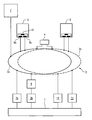
- the figure shows an unspecified automated process 1 in a highly schematic representation.
- Such an automated process 1 can be, for example, a chemical, process engineering or biotechnological process, an industrial manufacturing process or even a process for the transmission and distribution of water, gas or to be electrical energy.
- the process 1 is a process for the transmission and distribution of electrical energy, for example an electrical energy transmission network.
- the process are next to actuator devices 11, such.
- actuator devices 11 such.
- data acquisition devices 2a to 2c in conjunction.
- These data acquisition devices may be sensors as well as conventional current or voltage transformers, for example toroidal core transformers, or so-called unconventional converters, such as Rogowski coils or optical converters.
- the measured value detection devices 2a to 2c are connected in their execution corresponding manner with the process 1; This is indicated in the figure by a dashed line.
- the measured value detection devices 2a to 2c are also indirectly or directly in communication with a data transmission network 3, which consists of two redundantly constructed subnetworks 3a and 3b, of which the sub-network 3b is shown in dashed lines in the figure for clarity.
- a data transmission network 3 which consists of two redundantly constructed subnetworks 3a and 3b, of which the sub-network 3b is shown in dashed lines in the figure for clarity.
- the subnetworks 3a, 3b are networks in ring structure; Alternatively, of course, a conventional star structure can be used.
- the two subnetworks 3a and 3b are coupled together via a switch 4 so that data can be transmitted from one subnetwork 3a to the other subnetwork 3b and vice versa.
- the data transmission network 3 is preferably an Ethernet network in the form of a so-called real-time Ethernet network.
- An IEC international working group is currently responsible for the standardization of this Ethernet standard.
- the field device 5 may be, for example, an electrical protection device and the field device 6 may be a process control device.
- a master computer 7 which may be, for example, a station master computer or a central master computer in a so-called control center.
- the measured-value acquisition device 2b has no integrated analog-to-digital converter and no network connection, so that it first transmits its recorded measured values to a conversion device 8, also referred to as "merging Unit ", which then performs an analog-to-digital conversion and conversion of the measured values into digital measurement data in accordance with the first communication protocol used in the data transmission network 3.
- the conversion device has a network connection via which it transmits the measurement data directly to the data transmission network 3 can pass.
- the digital measurement data are transmitted in the data transmission network 3 to the field devices 5 and 6, with which automation and control functions are performed on the basis of the transmitted measurement data.
- the field devices 5 and 6 can in turn import control data into the data transmission network 3 which are transmitted in accordance with a second communication protocol, for example the communication protocol IEC 61850-8-1.
- the IEC for IEC-61850 compliant systems has defined the transmission of digital monitoring data, control data and control center data, collectively referred to herein as control data.
- the digital control data can be transmitted to the host computer 7, which can carry out further processing, archiving and processing of the data.
- digital control data may be transmitted to the actuator devices, such as power switch controls, which in turn may affect the process.
- the field devices 5 and 6 can have direct influence on the process 1 via the data transmission network 3.
- the time synchronization of the individual data transmitted via the data transmission network 3 often plays a very important role. In previous automation systems, this mostly had to a separate synchronization network can be set up, which distributed a time clock generated by a central timer location, for example one pulse per second, to the individual components of the automation system, so that an accurate time stamping of the transmitted and received digital data could take place.
- the Real-Time Ethernet network standard does not need such a separate synchronization network.
- controllers or specially designed integrated circuit components in the form of application-specific integrated circuit (ASIC), FPGAs (Field Programmable Gate Array) or EPLDs (Electrically Programmable Logic Device) are used. which according to the Real-Time Ethernet standard can make a corresponding time identification of the digital measurement or control data. This makes the design of the automation system significantly easier.
- the network connection of the field devices 5 and 6 can, for example, as shown schematically in the figure, have a network connection device with exactly two external ports 91, 9b, with which the field device is connected to the data transmission network 3.
- the network connection device may have exactly one internal port 10, with which it communicates with the corresponding field device.
- the ports 9a, 9b and 10 are connected to each other via a corresponding hard-wired circuit, for example, in the German patent application DE 102 60 806 A1 is described.
- Such a network connection device simultaneously provides a switch functionality, so that received and transmitted data without delay between the individual ports of the network connection device can be transmitted and thus no relevant loss of time in the data transmission in the data transmission network 3 occurs.
- the actuator devices 11 corresponding network connection devices may be present.
Landscapes
- Engineering & Computer Science (AREA)
- Physics & Mathematics (AREA)
- General Physics & Mathematics (AREA)
- Automation & Control Theory (AREA)
- General Engineering & Computer Science (AREA)
- Manufacturing & Machinery (AREA)
- Quality & Reliability (AREA)
- Arrangements For Transmission Of Measured Signals (AREA)
- Small-Scale Networks (AREA)
Description
- Die Erfindung betrifft ein Automatisierungssystem mit mindestens einer an einen automatisierten Prozess angeschlossenen Messwerterfassungseinrichtung und zumindest einem mit der mindestens einen Messwerterfassungseinrichtung in Verbindung stehenden Feldgerät und einem mit dem zumindest einen Feldgerät in Verbindung stehenden Leitrechner.
- Ein solches Automatisierungssystem ist beispielsweise aus dem Informationsblatt "SICAM HV - Digitale Leistungsschaltersteuerung (Digital Breaker Control DBC)", Bestellnr. E5001-U113-A230/1 der Siemens AG bekannt. Das Informationsblatt zeigt nämlich ein Automatisierungssystem mit mehreren Busebenen für einen automatisierten Prozess, in diesem Fall um ein Energieversorgungsnetz. Über einen sogenannten Prozessbus sind Wandler als Messwerterfassungseinrichtungen und Schaltersteuerungen mit Feldgeräten in Form von Prozessleitgeräten und Schutzgeräten verbunden. Die Feldgeräte wiederum sind über einen sogenannten Feldbus mit einer Nahsteuerung als Leitrechner verbunden. Über den Prozessbus werden üblicherweise neben Steuerbefehlen für die Schaltersteuerungen die von den Wandlern erfassten Messdaten, wie Strom- und Spannungsmesswerte, an die Feldgeräte übermittelt. Die Feldgeräte können zudem von dem Leitrechner über den Feldbus Steuerbefehle erhalten und in umgekehrter Richtung Informationen über den automatisierten Prozess an die Nahsteuerung beispielsweise zur Informationsdarstellung auf einem Anzeigesystem in einer Leitwarte weitergeben.
- Der Erfindung liegt die Aufgabe zugrunde, ein gattungsgemäßes Automatisierungssystem hinsichtlich seines Aufbaus noch weiter zu vereinfachen.
- Diese Aufgabe wird erfindungsgemäß durch ein Automatisierungssystem der oben angegebenen Art gelöst, bei dem die mindestens eine Messwerterfassungseinrichtung, das zumindest eine Feldgerät und der Leitrechner mit einem gemeinsamen Datenübertragungsnetzwerk verbunden sind, das zur Übertragung von digitalen Messdaten von der mindestens einen Messwerterfassungseinrichtung an das zumindest eine Feldgerät nach einem ersten Kommunikationsprotokoll und zur Übertragung von digitalen Steuerdaten zwischen dem zumindest einen Feldgerät und dem Leitrechner nach einem zweiten Kommunikationsprotokoll eingerichtet ist. Das erfindungsgemäße Automatisierungssystem weist anstelle zweier voneinander unabhängiger Bussysteme nur noch ein Datenübertragungsnetzwerk auf, mit dem alle Komponenten des Automatisierungssystems in Verbindung stehen. Um sowohl digitale Messdaten als auch digitale Steuerdaten über das Datenübertragungsnetzwerk übertragen zu können, ist dieses zur Übertragung der jeweiligen Daten nach unterschiedlichen Kommunikationsprotokollen geeignet. Dadurch, dass nur noch ein Netzwerk besteht, an das alle Komponenten des Automatisierungssystems angeschlossen sind, wird der Aufbau des Automatisierungssystems weiter vereinfacht.
- Aus der Dokument
US 4,901,281 wird ein Automatisierungssystem offenbart, in dem sämtliche Kommunikationsbeteiligte an dem Datenübertragungsnetzwerk über Kommunikationsadapter mit dem Datenübertragungsnetzwerk in Verbindung stehen, so dass das Datenübertragungsnetzwerk lediglich zur Übertragung eines einzigen Kommunikationsprotokolls eingerichtet ist. - Gemäß einer vorteilhaften Ausführungsform des erfindungsgemäßen Automatisierungssystems ist das Datenübertragungsnetzwerk ein Real-Time Ethernet Netzwerk. Die Verwendung eines Real-Time Ethernet Netzwerkes erlaubt es aufgrund hoher Übertragungsraten und vorhersagbarer Übertragungsdauern, Echtzeit-Applikationen in dem Automatisierungssystem durchzuführen. Außerdem kann durch das Real-Time Ethernet Netzwerk zu-dem eine Synchronisierung von an das Datenübertragungsnetzwerk übergebenen Messdaten und Steuerbefehlen stattfinden.
- Außerdem sieht eine vorteilhafte Weiterbildung des erfindungsgemäßen Automatisierungssystems vor, dass mit dem Datenübertragungsnetzwerk auch Aktoreinrichtungen verbunden sind, die ausgangsseitig mit dem automatisierten Prozess in Verbindung stehen. In diesem Fall sind auch Aktoren, wie z. B. Leistungsschaltersteuerungen in das gemeinsame Datenübertragungsnetzwerk eingebunden.
- Eine weitere vorteilhafte Ausführungsform des erfindungsgemäßen Automatisierungssystems sieht vor, dass das Datenübertragungsnetzwerk in Ringstruktur ausgebildet ist. Eine solche Netzwerkstruktur entspricht meist am besten dem Aufbau und den örtlichen Gegebenheiten eines Automatisierungssystems.
- Gemäß einer weiteren vorteilhaften Ausführungsform des erfindungsgemäßen Automatisierungssystems ist vorgesehen, dass das Datenübertragungsnetzwerk aus zumindest zwei redundant zueinander aufgebauten Teilnetzwerken besteht. Auf diese Weise kann die Verfügbarkeit und Zuverlässigkeit der Anlage weiter gesteigert werden.
- Gemäß einer vorteilhaften Ausführungsform des erfindungsgemäβen Automatisierungssystems ist ferner vorgesehen, dass die mindestens eine Messwerterfassungseinrichtung einen Analog/Digital-Umsetzer und eine Netzwerkanschlusseinrichtung zum Anschluss an das Datenübertragungsnetzwerk aufweist. Auf diese Weise können Messwerterfassungseinrichtungen besonders einfach und ohne zusätzliche Bauteile an das Datenübertragungsnetzwerk angeschlossen werden.
- Um auch bereits vorhandene Messwerterfassungseinrichtungen in dem erfindungsgemäßen Automatisierungssystem betreiben zu können, ist gemäß einer alternativen Ausführungsform vorgesehen, dass die zumindest eine Messwerterfassungseinrichtung zur Umsetzung der Messdaten in das erste Kommunikationsprotokoll mit einer Umsetzungseinrichtung verbunden ist, die ausgangsseitig mit dem Datenübertragungsnetzwerk verbunden ist.
- Eine weitere vorteilhafte Ausführungsform des erfindungsgemäβen Automatisierungssystems sieht schließlich vor, dass das zumindest eine Feldgerät und/oder die mindestens eine Messwerterfassungseinrichtung jeweils über eine Netzwerkanschlusseinrichtung mit dem Datenübertragungsnetzwerk verbunden ist, wobei die Netzwerkanschlusseinrichtung genau einen mit dem zumindest einen Feldgerät oder der Messwerterfassungseinrichtung verbundenen internen Port und genau zwei mit dem Datenübertragungsnetzwerk verbundene externe Ports aufweist. Solche Netzwerkanschlusseinrichtungen, wie sie beispielsweise aus der
DE 102 60 806 A1 bekannt sind, gewährleisten eine einfache Anschlussmöglichkeit der Feldgeräte und/oder Messwerterfassungseinrichtung an das Datenübertragungsnetzwerk. - Zur weiteren Erläuterung der Erfindung ist in der Figur in schematischer Darstellung der Aufbau eines Automatisierungssystems gezeigt.
- Die Figur zeigt hierbei einen nicht näher spezifizierten automatisierten Prozess 1 in höchst schematischer Darstellung. Ein solcher automatisierter Prozess 1 kann beispielsweise ein chemischer, verfahrenstechnischer oder biotechnologischer Prozess, ein industrieller Fertigungsprozess oder auch ein Prozess zur Übertragung und Verteilung von Wasser, Gas oder elektrischer Energie sein. Für die folgenden Ausführungen soll angenommen werden, dass es sich bei dem Prozess 1 um einen Prozess zur Übertragung und Verteilung elektrischer Energie, beispielsweise ein elektrisches Energieübertragungsnetz, handelt. Mit dem Prozess stehen neben Aktoreinrichtungen 11, wie z. B. Schaltersteuerungen, Messwerterfassungseinrichtungen 2a bis 2c in Verbindung. Bei diesen Messwerterfassungseinrichtungen kann es sich um Sensoren sowie konventionelle Strom- oder Spannungswandler, beispielsweise um Ringkernwandler, oder um sogenannte unkonventionelle Wandler, wie Rogowski-Spulen oder optische Wandler, handeln. Die Messwerterfassungseinrichtungen 2a bis 2c sind in ihrer Ausführung entsprechender Weise mit dem Prozess 1 verbunden; dies ist in der Figur durch eine strichliert dargestellte Linie angedeutet. Die Messwerterfassungseinrichtungen 2a bis 2c stehen außerdem mittelbar oder unmittelbar mit einem Datenübertragungsnetzwerk 3 in Verbindung, das aus zwei redundant zueinander aufgebauten Teilnetzwerken 3a und 3b besteht, von denen das Teilnetzwerk 3b in der Figur der Übersichtlichkeit halber strichliert dargestellt ist. Obwohl in diesem Ausführungsbeispiel auf zwei Teilnetzwerke Bezug genommen wird, können in der Praxis natürlich beliebig viele Teilnetzwerke vorhanden sein. Bei den Teilnetzwerken 3a, 3b handelt es sich gemäß der Figur 1 um Netzwerke in Ringstruktur; alternativ kann natürlich auch eine herkömmliche Sternstruktur verwendet werden. Die beiden Teilnetzwerke 3a und 3b sind über einen Switch 4 miteinander gekoppelt, so dass Daten von dem einen Teilnetzwerk 3a in das andere Teilnetzwerk 3b und umgekehrt übertragen werden können. Bei dem Datenübertragungsnetzwerk 3 handelt es sich vorzugsweise um ein Ethernet-Netzwerk in Form eines sogenannten Real-Time Ethernet-Netzwerkes. Eine internationale Arbeitsgruppe der IEC ist momentan mit der Normung dieses Ethernet Standards betraut.
- An das Datenübertragungsnetzwerk 3 sind außerdem Feldgeräte 5 und 6 angeschlossen. Dabei kann es sich bei dem Feldgerät 5 beispielsweise um ein elektrisches Schutzgerät und bei dem Feldgerät 6 um ein Prozessleitgerät handeln. Ferner steht mit dem Datenübertragungsnetzwerk 3 ein Leitrechner 7 in Verbindung, bei dem es sich beispielsweise um einen Stationsleitrechner oder um einen zentralen Leitrechner in einer sogenannten Leitstelle handeln kann.
- Im Folgenden soll die Funktionsweise des beschriebenen Automatisierungssystems erläutert werde:
- Über die Messwerterfassungseinrichtungen 2a bis 2c werden den Prozess 1 beschreibende Messwerte erfasst, beispielsweise kann es sich dabei um Strom- und Spannungsmesswerte handeln. Hierbei weisen die Messwerterfassungseinrichtungen 2a und 2c bereits eine Analog-Digital-Umwandlungseinrichtung und eine Einrichtung zur Netzwerkanbindung auf. Somit können die Messwerterfassungseinrichtungen 2a und 2c direkt an das Datenübertragungsnetzwerk 3 angeschlossen werden und liefern den aufgenommenen Messwerten entsprechende digitale Messdaten gemäß einem ersten Kommunikationsprotokoll an das Datenübertragungsnetzwerk 3. Bei diesem ersten Kommunikationsprotokoll kann es sich beispielsweise um das Kommunikationsprotokoll IEC 61850-9-2 handeln, mit dem die IEC die Übertragung digitaler Abtastwerte in Systemen, die gemäß der IEC 61850 Norm ausgelegt sind, festgelegt hat.
- Der Messwerterfassungseinrichtungen 2b weist hingegen keinen integrierten Analog-Digital-Umsetzer und keinen Netzwerkanschluss auf, so dass diese ihre aufgenommenen Messwerte zunächst an eine Umsetzeinrichtung 8, auch als sogenannte "Merging Unit" bezeichnet, überträgt, die anschließend eine Analog-Digital-Umwandlung und eine Umsetzung der Messwerte in digitale Messdaten gemäß dem in dem Datenübertragungsnetzwerk 3 verwendeten ersten Kommunikationsprotokoll vornimmt. Die Umsetzeinrichtung weist einen Netzwerkanschluss auf, über den sie die Messdaten direkt an das Datenübertragungsnetzwerk 3 übergeben kann.
- Die digitalen Messdaten werden in dem Datenübertragungsnetzwerk 3 an die Feldgeräte 5 und 6 übertragen, mit denen Automatisierungs- und Steuerfunktionen auf Grundlage der übertragenen Messdaten durchgeführt werden. Die Feldgeräte 5 und 6 können in das Datenübertragungsnetzwerk 3 wiederum Steuerdaten einspielen, die gemäß einem zweiten Kommunikationsprotokoll, beispielsweise dem Kommunikationsprotokoll IEC 61850-8-1, übertragen werden. Mit diesem Protokoll hat die IEC für IEC-61850 konforme Systeme die Übertragung digitaler Überwachungsdaten, Steuerdaten und Leitstellendaten festgelegt, die hier zusammengefasst als Steuerdaten bezeichnet werden. Die digitalen Steuerdaten können einerseits an den Leitrechner 7 übertragen werden, der eine weitere Verarbeitung, Archivierung und Aufbereitung der Daten vornehmen kann. Außerdem können digitale Steuerdaten an die Aktoreinrichtungen, wie beispielsweise Leistungsschaltersteuerungen, übertragen werden, die wiederum auf den Prozess einwirken können. So können über das Datenübertragungsnetzwerk 3 die Feldgeräte 5 und 6 direkten Einfluss auf den Prozess 1 nehmen.
- In industriellen Automatisierungssystemen wie dem hier dargestellten Automatisierungssystem spielt häufig die zeitliche Synchronisierung der einzelnen über das Datenübertragungsnetzwerk 3 übertragenen Daten eine sehr wichtige Rolle. In bisherigen Automatisierungssystemen musste hierfür zumeist ein separates Synchronisationsnetzwerk eingerichtet werden, das einen von einer zentralen Zeitgeberstelle generierten Zeittakt, beispielsweise ein Impuls pro Sekunde, an die einzelnen Komponenten des Automatisierungssystems verteilte, so dass hierüber eine genaue Zeitstempelung der gesendeten und empfangenen digitalen Daten stattfinden konnte. Der Real-Time Ethernet Netzwerkstandard benötigt ein solches separates Synchronisationsnetz nicht. Hier werden auf Seiten aller mit dem Datenübertragungsnetzwerk in Verbindung stehender Komponenten innerhalb der Netzwerkverbindung entsprechende Controller oder speziell ausgelegte integrierte Schaltungsbausteine in Form von ASICs (application specific integrated circuit), FPGAs (field programmable gate array) oder EPLDs (electrically programmable logic device) verwendet, die gemäß dem Real-Time Ethernet-Standard eine entsprechende Zeitkennzeichnung der digitalen Mess- oder Steuerdaten vornehmen können. Hierdurch vereinfacht sich der Aufbau des Automatisierungssystems entscheidend.
- Die Netzwerkanbindung der Feldgeräte 5 und 6 kann beispielsweise, wie in der Figur lediglich schematisch angedeutet, eine Netzwerkanschlusseinrichtung mit genau zwei externe Ports 91, 9b aufweisen, mit denen das Feldgerät an das Datenübertragungsnetzwerk 3 angeschlossen ist. Außerdem kann die Netzwerkanschlusseinrichtung genau einen internen Port 10 aufweisen, mit dem sie dem entsprechenden Feldgerät in Verbindung steht. Die Ports 9a, 9b und 10 sind über eine entsprechende fest verdrahtete Schaltung miteinander verbunden, die beispielsweise in der deutschen Patentanmeldung
DE 102 60 806 A1 beschrieben ist. Eine solche Netzwerkanschlusseinrichtung stellt gleichzeitig eine Switch-Funktionalität bereit, so dass empfangende und gesendete Daten ohne Zeitverzug zwischen den einzelnen Ports der Netzwerkanschlusseinrichtung übertragen werden können und somit kein relevanter Zeitverlust bei der Datenübertragung im Datenübertragungsnetzwerk 3 auftritt. In den Messwerterfassungseinrichtungen 2a,2b,2c und/oder den Aktoreinrichtungen 11 können entsprechende Netzwerkanschlusseinrichtungen vorhanden sein.
Claims (8)
- Automatisierungssystem mit mindestens einer an einen automatisierten Prozess (1) angeschlossenen Messwerterfassungseinrichtung (2a,2b,2c) und zumindest einem mit der mindestens einen Messwerterfassungseinrichtung (2a,2b,2c) in Verbindung stehenden Schutz- oder Prozessleitgerät (5,6) und einem mit dem zumindest einen Schutz- oder Prozessleitgerät (5,6) in Verbindung stehenden Leitrechner (7),
dadurch gekennzeichnet, dass- die mindestens eine Messwerterfassungseinrichtung (2a,2b,2c), das zumindest eine Schutz- oder Prozessleitgerät (5,6) und der Leitrechner (7) mit einem gemeinsamen Datenübertragungsnetzwerk (3) verbunden sind, das zur Übertragung von digitalen Messdaten von der mindestens einen Messwerterfassungseinrichtung (2a,2b,2c) an das zumindest eine Schutz- oder Prozessleitgerät (5,6) nach einem ersten Kommunikationsprotokoll und zur Übertragung von digitalen Steuerdaten zwischen dem zumindest einen Schutz- oder Prozessleitgerät (5,6) und dem Leitrechner (7) nach einem zweiten, von dem ersten Kommunikationsprotokoll verschiedenen Kommunikationsprotokoll eingerichtet ist. - Automatisierungssystem nach Anspruch 1,
dadurch gekennzeichnet, dass- das Datenübertragungsnetzwerk (3) ein Real-Time-Ethernet Netzwerk ist. - Automatisierungssystem nach Anspruch 1 oder Anspruch 2,
dadurch gekennzeichnet, dass- mit dem Datenübertragungsnetzwerk (3) auch Aktoreinrichtungen (11) verbunden sind, die ausgangsseitig mit dem automatisierten Prozess (1) in Verbindung stehen. - Automatisierungssystem nach einem der vorangehenden Ansprüche,
dadurch gekennzeichnet, dass- das Datenübertragungsnetzwerk (3) in Ringstruktur ausgebildet ist. - Automatisierungssystem nach einem der vorangehenden Ansprüche,
dadurch gekennzeichnet, dass- das Datenübertragungsnetzwerk (3) aus zumindest zwei redundant zueinander aufgebauten Teilnetzwerken (3a,3b) besteht. - Automatisierungssystem nach einem der vorangehenden Ansprüche,
dadurch gekennzeichnet, dass- die mindestens eine Messwerterfassungseinrichtung (2a,2b,2c) einen Analog/Digital-Umsetzer und eine Netzwerkanschlusseinrichtung zum Anschluss an das Datenübertragungsnetzwerk aufweist. - Automatisierungssystem nach einem der Ansprüche 1 bis 5,
dadurch gekennzeichnet, dass- die zumindest eine Messwerterfassungseinrichtung (2a,2b,2c) zur Umsetzung der Messdaten in das erste Kommunikationsprotokoll mit einer Umsetzungseinrichtung (8) verbunden ist, die ausgangsseitig mit dem Datenübertragungsnetzwerk (3) verbunden ist. - Automatisierungssystem nach einem der vorangehenden Ansprüche,
dadurch gekennzeichnet, dass- das zumindest eine Schutz- oder Prozessleitgerät (5,6) und/oder die mindestens eine Messwerterfassungseinrichtung (2a,2b,2c) jeweils über eine Netzwerkanschlusseinrichtung mit dem Datenübertragungsnetzwerk (3) verbunden ist, wobei die Netzwerkanschlusseinrichtung genau einen mit dem zumindest einen Schutz- oder Prozessleitgerät (5,6) oder der Messwerterfassungseinrichtung (2a,2b,2c) verbundenen internen Port (10) und genau zwei mit dem Datenübertragungsnetzwerk (3) verbundene externe Ports (9a,9b) aufweist.
Applications Claiming Priority (2)
| Application Number | Priority Date | Filing Date | Title |
|---|---|---|---|
| DE102005002743A DE102005002743A1 (de) | 2005-01-17 | 2005-01-17 | Automatisierungssystem |
| PCT/EP2006/050063 WO2006074981A1 (de) | 2005-01-17 | 2006-01-06 | Automatisierungssystem |
Publications (2)
| Publication Number | Publication Date |
|---|---|
| EP1851597A1 EP1851597A1 (de) | 2007-11-07 |
| EP1851597B1 true EP1851597B1 (de) | 2013-08-28 |
Family
ID=36178244
Family Applications (1)
| Application Number | Title | Priority Date | Filing Date |
|---|---|---|---|
| EP06704586.4A Revoked EP1851597B1 (de) | 2005-01-17 | 2006-01-06 | Automatisierungssystem |
Country Status (5)
| Country | Link |
|---|---|
| US (1) | US7617011B2 (de) |
| EP (1) | EP1851597B1 (de) |
| CN (1) | CN101107578B (de) |
| DE (1) | DE102005002743A1 (de) |
| WO (1) | WO2006074981A1 (de) |
Cited By (1)
| Publication number | Priority date | Publication date | Assignee | Title |
|---|---|---|---|---|
| DE102013218643A1 (de) * | 2013-09-17 | 2015-03-19 | Siemens Aktiengesellschaft | Steuereinrichtung und Datenübertragungsanordnung mit Steuereinrichtung zum Steuern mindestens eines Schalterfernantriebes für mindestens einen Trenn- und/oder Lasttrennschalter in einem elektrischen Energieversorgungsnetz |
Families Citing this family (7)
| Publication number | Priority date | Publication date | Assignee | Title |
|---|---|---|---|---|
| WO2006128394A1 (de) * | 2005-06-01 | 2006-12-07 | Siemens Aktiengesellschaft | Universelles mess- oder schutzgerät |
| ATE441137T1 (de) * | 2006-07-25 | 2009-09-15 | Siemens Ag | Mit mindestens zwei protokollen arbeitendes feldgerät |
| DE102007058609A1 (de) * | 2006-12-29 | 2008-07-03 | Codewrights Gmbh | Verfahren zur Installation von Objekten für ein komponentenbasiertes Managementsystem für Feldgeräte der Automatisierungstechnik |
| EP2112741A1 (de) * | 2008-04-22 | 2009-10-28 | ABB Schweiz AG | Leistungselektronikregler und Kommunikationsverfahren |
| US20100082844A1 (en) * | 2008-09-30 | 2010-04-01 | Abb Research Ltd. | Field device controller adapter |
| EP2273644A1 (de) | 2009-07-07 | 2011-01-12 | ABB Research Ltd. | Automatisierungssystem für eine Verteilerstation mit Schutzfunktionen |
| US9046414B2 (en) | 2012-09-21 | 2015-06-02 | Google Inc. | Selectable lens button for a hazard detector and method therefor |
Family Cites Families (17)
| Publication number | Priority date | Publication date | Assignee | Title |
|---|---|---|---|---|
| US4901218A (en) * | 1987-08-12 | 1990-02-13 | Renishaw Controls Limited | Communications adaptor for automated factory system |
| US6694270B2 (en) * | 1994-12-30 | 2004-02-17 | Power Measurement Ltd. | Phasor transducer apparatus and system for protection, control, and management of electricity distribution systems |
| AU4669397A (en) | 1996-10-04 | 1998-04-24 | Fisher Controls International Inc. | Process control network with redundant field devices and busses |
| CN1177266C (zh) * | 1997-10-13 | 2004-11-24 | 罗斯蒙德公司 | 工业过程中现场的过程设备及其形成方法 |
| US6483846B1 (en) * | 1998-07-10 | 2002-11-19 | Honeywell Inc. | Middleware-based real-time communication system |
| US6560235B1 (en) * | 1998-11-16 | 2003-05-06 | Woodhead Industries, Inc. | Universal communication system |
| DE10055938A1 (de) * | 2000-11-10 | 2002-05-23 | Hirschmann Electronics Gmbh | Datenübertragung |
| US20020103946A1 (en) * | 2001-01-31 | 2002-08-01 | Martin Gaiser | Data transmission devices and data communication systems capable of operating with a plurality of protocols |
| US6959356B2 (en) * | 2001-07-30 | 2005-10-25 | Fisher-Rosemount Systems, Inc. | Multi-protocol field device and communication method |
| DE10244845A1 (de) * | 2002-09-20 | 2004-04-08 | Siemens Ag | Anordnung zum Steuern und Überwachen einer Schaltanlage |
| US20040205111A1 (en) * | 2002-11-15 | 2004-10-14 | Zaki Chasmawala | User configurable data messages in industrial networks |
| DE10260806A1 (de) * | 2002-12-23 | 2004-07-08 | Siemens Ag | Netzwerkanschaltung, insbesondere Ethernet-Anschaltung |
| DE202004000928U1 (de) * | 2004-01-21 | 2004-07-29 | Brinkhus, Hartmut B., Dr. | Schaltungsanordnung zur Codeumwandlung |
| JP2007536634A (ja) * | 2004-05-04 | 2007-12-13 | フィッシャー−ローズマウント・システムズ・インコーポレーテッド | プロセス制御システムのためのサービス指向型アーキテクチャ |
| US20070255126A1 (en) * | 2006-04-28 | 2007-11-01 | Moberg Sheldon B | Data communication in networked fluid infusion systems |
| US9111088B2 (en) * | 2006-08-14 | 2015-08-18 | Quantum Security, Inc. | Policy-based physical security system for restricting access to computer resources and data flow through network equipment |
| DE102007021099A1 (de) * | 2007-05-03 | 2008-11-13 | Endress + Hauser (Deutschland) Ag + Co. Kg | Verfahren zum Inbetriebnehmen und/oder Rekonfigurieren eines programmierbaren Feldmeßgeräts |
-
2005
- 2005-01-17 DE DE102005002743A patent/DE102005002743A1/de not_active Withdrawn
-
2006
- 2006-01-06 CN CN2006800024211A patent/CN101107578B/zh not_active Expired - Lifetime
- 2006-01-06 WO PCT/EP2006/050063 patent/WO2006074981A1/de not_active Ceased
- 2006-01-06 US US11/795,473 patent/US7617011B2/en not_active Expired - Lifetime
- 2006-01-06 EP EP06704586.4A patent/EP1851597B1/de not_active Revoked
Cited By (1)
| Publication number | Priority date | Publication date | Assignee | Title |
|---|---|---|---|---|
| DE102013218643A1 (de) * | 2013-09-17 | 2015-03-19 | Siemens Aktiengesellschaft | Steuereinrichtung und Datenübertragungsanordnung mit Steuereinrichtung zum Steuern mindestens eines Schalterfernantriebes für mindestens einen Trenn- und/oder Lasttrennschalter in einem elektrischen Energieversorgungsnetz |
Also Published As
| Publication number | Publication date |
|---|---|
| US20080154388A1 (en) | 2008-06-26 |
| CN101107578A (zh) | 2008-01-16 |
| HK1109466A1 (zh) | 2008-06-06 |
| CN101107578B (zh) | 2010-05-19 |
| DE102005002743A1 (de) | 2006-07-27 |
| US7617011B2 (en) | 2009-11-10 |
| WO2006074981A1 (de) | 2006-07-20 |
| EP1851597A1 (de) | 2007-11-07 |
Similar Documents
| Publication | Publication Date | Title |
|---|---|---|
| DE102012009494B4 (de) | Steuereinrichtung zum Steuern eines Sicherheitsgerätes | |
| DE102012014681B4 (de) | Verwendung eines lO-Links zur Anbindung eines Netzgerätes | |
| EP4097927B1 (de) | Spe-basierter geräteadapter zum anschliessen eines nicht ethernet-fähigen feldgerätes an ein ethernet-basiertes prozesssteuerungssystem | |
| EP0344609B1 (de) | Digitales Signalübertragungssystem für die Hausleittechnik | |
| EP2984530B1 (de) | Messumformerspeisegerät mit abschaltbarer funkschnittstelle | |
| EP3353610B2 (de) | Verbindungseinheit, überwachungssystem und verfahren zum betreiben eines automatisierungssystems | |
| DE3236812A1 (de) | Fernwirksystem | |
| CH702454A1 (de) | Anordnung mit einer übergeordneten Steuereinheit und zumindest einem mit der Steuereinheit verbindbaren intelligenten Feldgerät. | |
| DE102008036967A1 (de) | Universelle Schnittstelle für einen Wireless Adapter | |
| EP2988183A1 (de) | Fernwirkanordnung, system und verfahren zum beobachten und/oder steuern einer anlage | |
| EP2613463B1 (de) | Verfahren zur überwachung eines transmitters und entsprechender transmitter | |
| DE102018109307B3 (de) | 7Kommunikationssystem der Automatisierungs- und Prozesstechnik sowie Y-Weicheneinheit für ein solches Kommunikationssystem | |
| DE102005002743A1 (de) | Automatisierungssystem | |
| EP3821308B1 (de) | System zur erhebung von daten aus einer anlage der automatisierungstechnik | |
| DE102017213365B4 (de) | Kommunikationsvorrichtung, System und Verfahren | |
| EP1690390B1 (de) | Verfahren zur übertragung von daten über einen datenbus sowie system und gateway zur durchführung des verfahrens | |
| EP1805567B1 (de) | Verfahren und automatisierungssystem zum bedienen und/oder beobachten mindestens eines feldgerätes | |
| WO2013068268A1 (de) | Kommunikationsverfahren und kommunikationseinrichtung für die prozessindustrie | |
| DE102005059012B4 (de) | ASI-Sytem zum Anschluß mehrerer Sensoren und/oder Aktuatoren an eine Steuerung | |
| EP3741027B1 (de) | Schaltanlage für hoch- bzw. mittelspannungstechnik | |
| EP2989551B1 (de) | Verfahren und vorrichtung zur seriellen datenübertragung zwischen einem basismodul und einem ersten erweiterungsmodul | |
| EP1886448B1 (de) | Universelles mess- oder schutzgerät | |
| EP2187278A1 (de) | Steuerungsanbindung eines Sicherheitsschaltgerätes | |
| EP3930130B1 (de) | Verfahren zum parametrieren einer schutzanordnung, schutzanordnung und computerprogrammprodukt | |
| EP4704278A1 (de) | Verfahren und vorrichtung zum schutz, zur automatisierung und zur steuerung einer anlage |
Legal Events
| Date | Code | Title | Description |
|---|---|---|---|
| PUAI | Public reference made under article 153(3) epc to a published international application that has entered the european phase |
Free format text: ORIGINAL CODE: 0009012 |
|
| 17P | Request for examination filed |
Effective date: 20070713 |
|
| AK | Designated contracting states |
Kind code of ref document: A1 Designated state(s): DE FR GB IT |
|
| 17Q | First examination report despatched |
Effective date: 20071026 |
|
| DAX | Request for extension of the european patent (deleted) | ||
| RBV | Designated contracting states (corrected) |
Designated state(s): DE FR GB IT |
|
| RAP1 | Party data changed (applicant data changed or rights of an application transferred) |
Owner name: SIEMENS AKTIENGESELLSCHAFT |
|
| GRAP | Despatch of communication of intention to grant a patent |
Free format text: ORIGINAL CODE: EPIDOSNIGR1 |
|
| GRAS | Grant fee paid |
Free format text: ORIGINAL CODE: EPIDOSNIGR3 |
|
| GRAA | (expected) grant |
Free format text: ORIGINAL CODE: 0009210 |
|
| AK | Designated contracting states |
Kind code of ref document: B1 Designated state(s): DE FR GB IT |
|
| REG | Reference to a national code |
Ref country code: GB Ref legal event code: FG4D Free format text: NOT ENGLISH |
|
| REG | Reference to a national code |
Ref country code: DE Ref legal event code: R096 Ref document number: 502006013156 Country of ref document: DE Effective date: 20131024 |
|
| RAP2 | Party data changed (patent owner data changed or rights of a patent transferred) |
Owner name: SIEMENS AKTIENGESELLSCHAFT |
|
| PLBI | Opposition filed |
Free format text: ORIGINAL CODE: 0009260 |
|
| PLAX | Notice of opposition and request to file observation + time limit sent |
Free format text: ORIGINAL CODE: EPIDOSNOBS2 |
|
| 26 | Opposition filed |
Opponent name: WAGO KONTAKTTECHNIK GMBH & CO. KG Effective date: 20140528 |
|
| REG | Reference to a national code |
Ref country code: DE Ref legal event code: R026 Ref document number: 502006013156 Country of ref document: DE Effective date: 20140528 |
|
| PLBB | Reply of patent proprietor to notice(s) of opposition received |
Free format text: ORIGINAL CODE: EPIDOSNOBS3 |
|
| PGFP | Annual fee paid to national office [announced via postgrant information from national office to epo] |
Ref country code: DE Payment date: 20150320 Year of fee payment: 10 |
|
| REG | Reference to a national code |
Ref country code: FR Ref legal event code: PLFP Year of fee payment: 11 |
|
| REG | Reference to a national code |
Ref country code: DE Ref legal event code: R064 Ref document number: 502006013156 Country of ref document: DE Ref country code: DE Ref legal event code: R103 Ref document number: 502006013156 Country of ref document: DE |
|
| RDAF | Communication despatched that patent is revoked |
Free format text: ORIGINAL CODE: EPIDOSNREV1 |
|
| PGFP | Annual fee paid to national office [announced via postgrant information from national office to epo] |
Ref country code: IT Payment date: 20160127 Year of fee payment: 11 |
|
| PGFP | Annual fee paid to national office [announced via postgrant information from national office to epo] |
Ref country code: FR Payment date: 20160115 Year of fee payment: 11 Ref country code: GB Payment date: 20160111 Year of fee payment: 11 |
|
| RDAG | Patent revoked |
Free format text: ORIGINAL CODE: 0009271 |
|
| STAA | Information on the status of an ep patent application or granted ep patent |
Free format text: STATUS: PATENT REVOKED |
|
| 27W | Patent revoked |
Effective date: 20160309 |
|
| GBPR | Gb: patent revoked under art. 102 of the ep convention designating the uk as contracting state |
Effective date: 20160309 |