EP2984530B1 - Messumformerspeisegerät mit abschaltbarer funkschnittstelle - Google Patents
Messumformerspeisegerät mit abschaltbarer funkschnittstelle Download PDFInfo
- Publication number
- EP2984530B1 EP2984530B1 EP14706518.9A EP14706518A EP2984530B1 EP 2984530 B1 EP2984530 B1 EP 2984530B1 EP 14706518 A EP14706518 A EP 14706518A EP 2984530 B1 EP2984530 B1 EP 2984530B1
- Authority
- EP
- European Patent Office
- Prior art keywords
- transmitter power
- unit
- radio module
- power unit
- field device
- Prior art date
- Legal status (The legal status is an assumption and is not a legal conclusion. Google has not performed a legal analysis and makes no representation as to the accuracy of the status listed.)
- Active
Links
Images
Classifications
-
- G—PHYSICS
- G05—CONTROLLING; REGULATING
- G05B—CONTROL OR REGULATING SYSTEMS IN GENERAL; FUNCTIONAL ELEMENTS OF SUCH SYSTEMS; MONITORING OR TESTING ARRANGEMENTS FOR SUCH SYSTEMS OR ELEMENTS
- G05B19/00—Program-control systems
- G05B19/02—Program-control systems electric
- G05B19/04—Program control other than numerical control, i.e. in sequence controllers or logic controllers
- G05B19/042—Program control other than numerical control, i.e. in sequence controllers or logic controllers using digital processors
-
- H—ELECTRICITY
- H04—ELECTRIC COMMUNICATION TECHNIQUE
- H04B—TRANSMISSION
- H04B1/00—Details of transmission systems, not covered by a single one of groups H04B3/00 - H04B13/00; Details of transmission systems not characterised by the medium used for transmission
- H04B1/005—Details of transmission systems, not covered by a single one of groups H04B3/00 - H04B13/00; Details of transmission systems not characterised by the medium used for transmission adapting radio receivers, transmitters andtransceivers for operation on two or more bands, i.e. frequency ranges
- H04B1/0053—Details of transmission systems, not covered by a single one of groups H04B3/00 - H04B13/00; Details of transmission systems not characterised by the medium used for transmission adapting radio receivers, transmitters andtransceivers for operation on two or more bands, i.e. frequency ranges with common antenna for more than one band
- H04B1/006—Details of transmission systems, not covered by a single one of groups H04B3/00 - H04B13/00; Details of transmission systems not characterised by the medium used for transmission adapting radio receivers, transmitters andtransceivers for operation on two or more bands, i.e. frequency ranges with common antenna for more than one band using switches for selecting the desired band
-
- H—ELECTRICITY
- H04—ELECTRIC COMMUNICATION TECHNIQUE
- H04W—WIRELESS COMMUNICATION NETWORKS
- H04W76/00—Connection management
- H04W76/20—Manipulation of established connections
-
- G—PHYSICS
- G05—CONTROLLING; REGULATING
- G05B—CONTROL OR REGULATING SYSTEMS IN GENERAL; FUNCTIONAL ELEMENTS OF SUCH SYSTEMS; MONITORING OR TESTING ARRANGEMENTS FOR SUCH SYSTEMS OR ELEMENTS
- G05B2219/00—Program-control systems
- G05B2219/20—Pc systems
- G05B2219/25—Pc structure of the system
- G05B2219/25187—Transmission of signals, medium, ultrasonic, radio
-
- G—PHYSICS
- G05—CONTROLLING; REGULATING
- G05B—CONTROL OR REGULATING SYSTEMS IN GENERAL; FUNCTIONAL ELEMENTS OF SUCH SYSTEMS; MONITORING OR TESTING ARRANGEMENTS FOR SUCH SYSTEMS OR ELEMENTS
- G05B2219/00—Program-control systems
- G05B2219/20—Pc systems
- G05B2219/25—Pc structure of the system
- G05B2219/25428—Field device
-
- G—PHYSICS
- G05—CONTROLLING; REGULATING
- G05B—CONTROL OR REGULATING SYSTEMS IN GENERAL; FUNCTIONAL ELEMENTS OF SUCH SYSTEMS; MONITORING OR TESTING ARRANGEMENTS FOR SUCH SYSTEMS OR ELEMENTS
- G05B2219/00—Program-control systems
- G05B2219/30—Nc systems
- G05B2219/33—Director till display
- G05B2219/33192—Radio link, wireless
-
- H—ELECTRICITY
- H04—ELECTRIC COMMUNICATION TECHNIQUE
- H04B—TRANSMISSION
- H04B5/00—Near-field transmission systems, e.g. inductive or capacitive transmission systems
- H04B5/20—Near-field transmission systems, e.g. inductive or capacitive transmission systems characterised by the transmission technique; characterised by the transmission medium
Definitions
- the invention relates to a transmitter power supply, a system for use in automation technology and a method for operating the system.
- field devices are often used to detect and / or influence process variables.
- field devices are level gauges, mass flowmeters, pressure and temperature measuring devices, pH redox potential measuring devices, conductivity meters, etc., which detect the corresponding process variables level, flow, pressure, temperature, pH or conductivity value as sensors.
- actuators z.
- valves that control the flow of a liquid in a pipe section or pumps that change the level in a container.
- the energy and / or signal transmission between field devices and higher-level units is often carried out according to the known 4 to 20 mA standard, in which a 4 to 20 mA current loop or a two-wire line between the field device and the parent unit is formed.
- the HART protocol is based on this 4 to 20 mA standard. With the aid of the HART protocol and the bi-directional communication thus enabled, the field devices described at the outset can be very flexibly parameterized, put into operation or read out data records stored on the field device.
- the HART protocol thus enables a very simple operation of the field device by means of a control unit.
- the data to be transmitted is modulated onto the 4 to 20 mA signal or the 4 to 20 mA current loop so as to communicate digitally between the field device and the operating unit, while at the same time the analog signal transmission takes place.
- the measured values detected by the sensor are transmitted as an analog current signal via the two-wire line to the higher-order unit.
- the measuring range of the sensors is linearly mapped to the 4 to 20 mA current signal.
- mutual communication is available via the digital HART communication in order, for example, to carry out a parameterization of the field device by means of the operating unit.
- there are other protocols such as Foundation Fieldbus, and / or Profibus PA, which enable similar functions to HART.
- the power supply of the field devices is also via the 4 to 20 mA current signal, so that in addition to the two-wire line no additional supply line is necessary.
- the power supply is not realized by the higher-level unit, but by a transmitter power supply, which is connected to the 4 to 20 mA current loop or the two-wire line and is typically arranged offset from the parent unit.
- Control units are known from the prior art, which are physically connected to the field device to the 4 to 20 mA current loop, so as to enable the operation of the field device via the 4 to 20 mA current loop by means of the HART protocol.
- Such operating units have the disadvantage that, as already mentioned, they must be physically connected or clamped to the 4 to 20 mA current loop.
- the two-wire line must be modified in such a way, for example, stripped and / or severed that the control unit can be connected.
- the actual analog current signal which transmits the measured values of the field device, is not transmitted for the period of connection of the operating unit. In other words, the analog transmission of the measured values is interrupted.
- radio modules for easier operation of field devices. Solutions are known in which the field devices have integrated radio modules. However, it has also become known to retrofit field devices with radio modules, so that the field devices can then be operated wirelessly by operating units which likewise have a radio module.
- radio module in addition to the field device in itself, must be supplied with energy.
- the power supply of the field devices and the radio module takes place, as mentioned above, via the 4 to 20 mA current loop.
- the supply of the 4 to 20 mA current loop with electrical energy is carried out, for example, via a transmitter power supply device described in the introduction. This provides the electrical voltage required to set a current value in the current loop. Often, the current supplied to the current loop is not sufficient to supply the field device with the energy required to operate the integrated radio module via the signal line.
- the WO 2008/127580 A2 hereby discloses a wireless process communication adapter which DE 10 2006 009979 A1 a device for wireless communication with a field device, the DE 10 2010 063226 A1 a field device with a wireless communication interface, the DE 10 2007 054923 A1 a method for operating a field device of industrial process and / or automation technology and the DE 10 2011 076708 A1 a radio unit for a system of process automation technology with a supply circuit.
- the invention has for its object to provide an increased ease of use for a field device, which is used in automation technology.
- the task is solved by a transmitter power supply, a system for use in automation technology and a method for operating the system.
- the object is achieved by a transmitter power supply for use in a control cabinet, which is connected via a first two-wire line with a field device and a second two-wire line to a parent unit, wherein the transmitter power supply includes at least one switch, a radio module and a circuit , wherein the radio module can be activated or deactivated by means of the switch and the circuit realizes the conversion between signals of the first two-wire line and signals of the radio module, so that the one connected via the first two-wire line to the transmitter power supply field device by means of the radio module of the transmitter power supply operated by a wireless communication link is when the radio module of the transmitter power supply can be activated by the switch.
- a radio module is integrated into a transmitter feed device, which enables the connection of at least one field device to a higher-level unit via a two-wire line.
- the radio module can be activated or deactivated via a switch so that an operating unit can communicate with the field device wirelessly with the aid of the transmitter feed device.
- the communication between the at least one field device and the operating unit is preferably carried out via the HART protocol described above.
- Foundation Fieldbus and / or Profibus PA it is also conceivable Foundation Fieldbus and / or Profibus PA.
- Integrating the radio module into the transmitter power supply provides a number of advantages.
- the clamping and disconnecting the control unit to the two-wire line is obsolete.
- a continuous communication between the field device and the higher-level unit is also given during the communication between the operating unit and the field device.
- radio does not need to be powered by the 4 to 20 mA 2-wire line because it is powered directly by the transmitter power supply. This reduces the maintenance effort, since a check of the proper power supply, eg. The battery condition, the radio module is no longer necessary.
- the switch that enables or disables the radio module makes it easier to control access to the field device. On the one hand, therefore, a conscious activation of the radio module of a specific field device by the operator and, on the other hand, the radio module is not activated continuously and thus the periods in which a manipulation can take place is significantly smaller.
- Another advantage results from the fact that the operation of a field device, which, for example. Sitting on a tank and thus not easily accessible is facilitated because the operation of the field device is made possible via the transmitter power supply, which typically arranged in easily accessible areas of the automation system is.
- a galvanic isolation between the field device and the higher-level unit is realized in the transmitter power supply.
- the radio module is designed such that the wireless communication connection is preferably possible by means of Bluetooth and / or near-field communication. It is also conceivable, however, a radio module, which allows a wireless communication connection, for example, according to ANT, WirelessHART, ZigBee, nanoNET.
- a mobile terminal is, for example, a smartphone, mobile phone, laptop, tablet PC, PDA, netbook, UMPC, etc. into consideration.
- the transmitter power supply is fixed by means of a DIN rail in the control cabinet.
- an operating software that enables the operation of the field device runs on the mobile terminal.
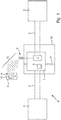
- FIG. 1 shows a system 8 for use in automation technology, which includes a transmitter supply unit 1, a field device 3 and a higher-level unit 4.
- the field device 3 is connected via a two-wire line 2 to the higher-level unit 4 in order to transmit or transfer measured values and / or manipulated values in the case of an actuator between the field device 3 and the higher-order unit 4.
- the parent unit 4 may, for. B. represent a control system or a control unit, which serve for process control, process visualization, process monitoring.
- the superordinate unit 4 is typically arranged offset from the field device 3 in a control room. From this higher-level unit 4, the two-wire line 2 goes via the transmitter power supply 1, which is attached to a top hat rail 11 in the control cabinet 10, to the field device 3.
- Such transmitter power supplies 1 are often centrally summarized in automation equipment in the cabinet 10 together.
- the transmitter supply unit 1 in this case comprises a switch 5, by means of which an integrated radio module 6 can be activated or deactivated, and a circuit 7 which controls the conversion between signals of the two-wire line 2 realized in accordance with the HART protocol and the signals of the radio module 6.
- the field device 3 which is connected to the transmitter supply unit 1, by means of the wireless module 6 by a wireless communication link 13 operable.
- the field device 3 connected to the transmitter supply device 1 can be operated via a mobile terminal 9, which has a unit 14 corresponding to the radio module 6 for the wireless communication connection 13.
- the radio module 6 and the corresponding unit 14 of the mobile terminal 9 are designed such that a wireless communication connection 13 by means of Bluetooth and / or near field communication is possible.
- a wireless communication connection 13 for example, according to ANT, WirelessHART, ZigBee and / or nanoNET is possible.
- On the mobile terminal 9 runs an operating software 12, which allows the operation of the field device 3.
- the field device 3 can be safely operated by means of the mobile terminal 9, for example by a service technician.
- the switch 5 of the transmitter supply device 1 must be operated such that the radio module 6 is activated.
- the structure of the wireless communication connection 13 between the radio module 6 of the transmitter supply unit 1 and the corresponding unit 14 of the mobile terminal 9 is then realized by means of the operating software 12.
- the field device 3 which is connected to the transmitter supply unit 1 and can be operated by the wireless communication connection 13 between the mobile terminal 9 and the radio module 6 of the transmitter supply unit 1, is operated.
- the switch 5 of the transmitter supply device 1 is actuated again, so that the radio module 6 is deactivated.
Landscapes
- Engineering & Computer Science (AREA)
- Computer Networks & Wireless Communication (AREA)
- Signal Processing (AREA)
- Physics & Mathematics (AREA)
- General Physics & Mathematics (AREA)
- Automation & Control Theory (AREA)
- Arrangements For Transmission Of Measured Signals (AREA)
- Computer Security & Cryptography (AREA)
- Selective Calling Equipment (AREA)
- Programmable Controllers (AREA)
Description
- Die Erfindung betrifft ein Messumformerspeisegerät, ein System zum Einsatz in der Automatisierungstechnik sowie ein Verfahren zum Bedienen des Systems.
- In der Prozessautomatisierungstechnik werden vielfach Feldgeräte eingesetzt, die zur Erfassung und/oder Beeinflussung von Prozessvariablen dienen. Beispiele für derartige Feldgeräte sind Füllstandsmessgeräte, Massendurchflussmessgeräte, Druck- und Temperaturmessgeräte, pH-Redoxpotential- Messgeräte, Leitfähigkeitsmessgeräte etc., die als Sensoren die entsprechenden Prozessvariablen Füllstand, Durchfluss, Druck, Temperatur, pH-Wert bzw. Leitfähigkeitswert erfassen.
- Zur Beeinflussung von Prozessvariablen dienen so genannte Aktoren, z. B. Ventile, die den Durchfluss einer Flüssigkeit in einem Rohrleitungsabschnitt steuern oder Pumpen, die den Füllstand in einem Behälter ändern.
- Eine Vielzahl solcher Feldgeräte wird von der Firma Endress + Hauser® hergestellt und vertrieben.
- Häufig sind Feldgeräte mit übergeordneten Einheiten z. B. Leitsystemen oder Steuereinheiten verbunden. Diese übergeordneten Einheiten dienen zur Prozesssteuerung, Prozessvisualisierung, Prozessüberwachung.
- Die Energie- und/oder Signalübertragung zwischen Feldgeräten und übergeordneten Einheiten erfolgt häufig nach dem bekannten 4 bis 20 mA Standard, bei dem eine 4 bis 20 mA Stromschleife bzw. eine Zweidrahtleitung zwischen dem Feldgerät und der übergeordneten Einheit ausgebildet ist.
- Auf diesem 4 bis 20 mA Standard baut das HART-Protokoll auf. Mit Hilfe des HART-Protokolls und der somit ermöglichten bidirektionalen Kommunikation, lassen sich die eingangs beschriebene Feldgeräte sehr flexibel parametrieren, in Betrieb nehmen oder auch Datensätze auslesen, die auf dem Feldgerät gespeichert sind. Das HART-Protokoll ermöglicht somit eine sehr einfache Bedienung des Feldgerätes mittels einer Bedieneinheit.
- Hierzu wird auf das 4 bis 20 mA Signal bzw. die 4 bis 20 mA Stromschleife die zu übertragenden Daten aufmoduliert, um so digital zwischen Feldgerät und der Bedieneinheit zu kommunizieren, während gleichzeitig die analoge Signalübertragung stattfindet.
- Handelt es sich bei den Feldgeräten bspw. um Sensoren, so werden die von dem Sensor erfassten Messwerte als analoges Stromsignal über die Zweidrahtleitung an die übergeordnete Einheit übertragen. Der Messbereich der Sensoren wird dabei linear auf das 4 bis 20 mA Stromsignal abgebildet. Gleichzeitig steht über die digitale HART Kommunikation eine wechselseitige Kommunikation zur Verfügung, um bspw. eine Parametrierung des Feldgerätes mittels der Bedieneinheit durchzuführen. Neben dem HART-Protokoll gibt es weitere Protokolle wie bspw. Foundation Fieldbus, und/oder Profibus PA die ähnliche Funktionen wie HART ermöglichen.
- Die Energieversorgung der Feldgeräte erfolgt ebenfalls über das 4 bis 20 mA Stromsignal, so dass neben der Zweidrahtleitung keine zusätzliche Versorgungsleitung notwendig ist. Normalerweise wird die Energieversorgung nicht durch die übergeordnete Einheit, sondern durch ein Messumformerspeisegerät realisiert, welches mit der 4 bis 20 mA Stromschleife bzw. der Zweidrahtleitung verbunden und typischerweise von der übergeordneten Einheit abgesetzt angeordnet ist.
- Für den Einsatz von Feldgeräten im Ex-Bereich sind gewisse Maßnahmen im Hinblick auf die Eigensicherheit notwendig. So ist eine galvanische Trennung bei der Übertragung der Signale zwischen der übergeordneten Einheit, die im sicheren Bereich angeordnet ist, und dem Feldgerät, das im eigensicheren Bereich angeordnet ist nötig.
- Aus dem Stand der Technik sind Bedieneinheiten bekannt, die zur Kommunikation mit dem Feldgerät physikalisch an die 4 bis 20 mA Stromschleife angeschlossen werden, um so die Bedienung des Feldgerätes über die 4 bis 20 mA Stromschleife mittels des HART-Protokolls zu ermöglichen. Derartige Bedieneinheiten weisen den Nachteil auf, dass sie, wie bereits erwähnt, physikalisch an die 4 bis 20 mA Stromschleife angeschlossen bzw. angeklemmt werden müssen. Hierzu muss die Zweidrahtleitung derartig modifiziert bspw. abisoliert und/oder durchtrennt werden, dass die Bedieneinheit angeschlossen werden kann. Dies führt dazu, dass das eigentliche analoge Stromsignal, welches die Messwerte des Feldgerätes überträgt, für den Zeitraum des Anschlusses der Bedieneinheit nicht übertragen wird. In anderen Worten wird die analoge Übertragung der Messwerte unterbrochen.
- Ebenfalls ist aus dem Stand der Technik bekannt, Funkmodule zur leichteren Bedienung von Feldgeräten zu verwenden. Es sind Lösungen bekannt, bei denen die Feldgeräte integrierte Funkmodule aufweisen. Es ist aber auch bekannt geworden, Feldgeräte mit Funkmodulen nachzurüsten, so dass die Feldgeräte dann drahtlos durch Bedieneinheiten, die ebenfalls ein Funkmodul aufweisen, bedient werden können.
- Derartige Lösungen weisen den Nachteil auf, dass das Funkmodul zusätzlich zu dem Feldgerät an sich, mit Energie versorgt werden muss. Die Energieversorgung der Feldgeräte als auch des Funkmoduls erfolgt dabei, wie eingangs erwähnt, über die 4 bis 20 mA Stromschleife. Die Speisung der 4 bis 20 mA Stromschleife mit elektrischer Energie erfolgt dabei bspw. über ein eingangs beschriebenes Messumformerspeisegerät. Dieses liefert die zum Einstellen eines Stromwertes in der Stromschleife erforderliche elektrische Spannung. Oftmals reicht die der Stromschleife zuführbare Energie nicht aus, um das Feldgerät mit der zum Betrieb des integrierten Funkmoduls benötigten Energie über die Signalleitung zu versorgen.
- Abhilfe wird diesem Nachteil geleistet, in dem, wie in der
DE 10 2004 020 393 A vorgeschlagen, eine separate Energieversorgung für das Funkmodul in Form einer Batterie vorgesehen ist. - Diese Lösung weist wiederum den Nachteil auf, dass die Wartung, insbesondere die Kontrolle des Batteriezustandes, einen erheblichen Aufwand für den Bediener eines solchen Feldgerätes darstellt.
- Darüber hinaus weisen derartige Lösungen den Nachteil auf, dass die Feldgeräte, die mit Funkmodulen ausgerüstet sind nicht immer kontrollierbar sind, so dass ungewolltes Bedienen oder auch eine bewusste Manipulationen ausgeschlossen oder verhindert werden kann. So kann es bspw. vorkommen, dass ein Bediener der sich in Reichweite des Funkmodules zur drahtlosen Kommunikation befindet, versehentlich mit einem Feldgerät verbindet und so ein ungewolltes Bedienen dieses Feldgerätes herbeiführt. Neben diesem ungewollten Bedienen kann es aber zu bewussten Handlungen in Form von Manipulationen an Feldgeräten, die mit solchen Funkmodulen ausgestattet sind, kommen. Speziell in großen Automatisierungsanlagen, in denen die Feldgeräte über einen weiten Bereich verteilt sind, ist eine effektive Kontrolle der Feldgeräte äußerst schwierig und es kann nicht ausgeschlossen werden, dass eine Manipulation, bspw. in Form eines Hackerangriffes, eines Feldgerätes stattfindet.
- Ferner sind aus dem Stand der Technik die
WO 2008/127580 A2 , dieDE 10 2006 009979 A1 , dieDE 10 2010 063226 A1 , dieDE 10 2007 054923 A1 sowie dieDE 10 2011 076708 A1 bekannt geworden. - Die
WO 2008/127580 A2 offenbart hierbei einen drahtlosen Prozesskommunikationsadapter, dieDE 10 2006 009979 A1 eine Einrichtung zur drahtlosen Kommunikation mit einem Feldgerät, dieDE 10 2010 063226 A1 ein Feldgerät mit einer drahtlosen Kommunikationsschnittstelle, dieDE 10 2007 054923 A1 ein Verfahren zum Betreiben eines Feldgerätes der industriellen Prozess- und/oder Automatisierungstechnik und dieDE 10 2011 076708 A1 eine Funkeinheit für eine Anlage der Prozessautomatisierungstechnik mit einer Versorgungsschaltung. - Der Erfindung liegt die Aufgabe zugrunde, ein erhöhte Bedienerfreundlichkeit für ein Feldgerät, welches in der Automatisierungstechnik eingesetzt wird, zu ermöglichen.
- Die Aufgabe wird durch ein Messumformerspeisegerät, ein System zum Einsatz in der Automatisierungstechnik sowie ein Verfahren zum Bedienen des Systems gelöst.
- Hinsichtlich des Messumformerspeisegerätes wird die Aufgabe erfindungsgemäß durch ein Messumformerspeisegerät zum Einsatz in einem Schaltschrank gelöst, welches über eine erste Zweidrahtleitung mit einem Feldgerät und über eine zweite Zweidrahtleitung mit einer übergeordneten Einheit verbunden ist, wobei das Messumformerspeisegerät zumindest einen Schalter, ein Funkmodul und eine Schaltung umfasst, wobei das Funkmodul mittels des Schalters aktivierbar oder deaktivierbar ist und die Schaltung die Umsetzung zwischen Signalen der ersten Zweidrahtleitung und Signalen des Funkmodules realisiert, so dass das eine über die erste Zweidrahtleitung an das Messumformerspeisegerät angeschlossene Feldgerät mittels des Funkmoduls des Messumformerspeisegerätes durch eine drahtlose Kommunikationsverbindung bedienbar ist, wenn das Funkmodul des Messumformerspeisegerätes durch den Schalter aktivierbar ist.
- Erfindungsgemäß wird in ein Messumformerspeisegerät, welches über eine Zweidrahtleitung die Anbindung zumindest eines Feldgerätes an eine übergeordnete Einheit ermöglicht, ein Funkmodul integriert. Über einen Schalter ist das Funkmodul aktivierbar bzw. deaktivierbar, so dass eine Bedieneinheit drahtlos mit Hilfe des Messumformerspeisegerätes mit dem Feldgerät kommunizieren kann. Die Kommunikation zwischen dem mindestens einen Feldgerät und der Bedieneinheit erfolgt hierbei vorzugsweise über das eingangs beschriebene HART-Protokoll. Denkbar ist aber auch Foundation Fieldbus und/oder Profibus PA.
- Durch die Integration des Funkmodules in das Messumformerspeisegerät ergibt sich eine Reihe von Vorteilen.
- So ist, durch die Integration eines Funkmodules in ein Messumformerspeisegerät zur Bedienung eines Feldgerätes, das Anklemmen und Abklemmen der Bedieneinheit an die Zweidrahtleitung hinfällig. Damit einhergehend ist eine kontinuierliche Kommunikation zwischen dem Feldgerät und der übergeordneten Einheit auch während der Kommunikation zwischen der Bedieneinheit und dem Feldgerät gegeben.
- Ein weiterer Vorteil besteht darin, dass das Funkmodul nicht mehr über die 4 bis 20 mA Zweidrahtleitung mit Energie versorgt werden muss, da es unmittelbar von dem Messumformerspeisegerät mit Energie versorgt wird. Hierdurch reduziert sich der Wartungsaufwand, da eine Kontrolle der ordnungsgemäßen Energieversorgung, bspw. des Batteriezustandes, des Funkmodules nicht mehr nötig ist.
- Darüber hinaus ist durch den Schalter, der das Funkmodul ein- bzw. auszuschalten, der Zugriff auf das Feldgerät einfacher zu kontrollieren. Zum einen bedarf es somit einer bewussten Aktivierung des Funkmodules eines spezifischen Feldgerätes durch den Bediener und zum anderen ist das Funkmodul nicht durchgängig aktiviert und somit die Zeiträume in denen eine Manipulation stattfinden kann deutlich kleiner.
- Ein weiterer Vorteil ergibt sich daraus, dass die Bedienung eines Feldgerätes, welches bspw. auf einem Tank sitzt und somit nicht ohne weiteres zugänglich ist erleichtert wird, da die Bedienung des Feldgerätes über das Messumformerspeisegerät ermöglicht wird, welches typischerweise in gut zugänglichen Bereichen der Automatisierungsanlage angeordnet ist.
- Gemäß einer vorteilhaften Ausgestaltung ist in dem Messumformerspeisegerät eine galvanische Trennung zwischen dem Feldgerät und der übergeordneten Einheit realisiert.
- Gemäß einer weiteren vorteilhaften Ausgestaltung ist das Funkmodul derartig ausgebildet, dass die drahtlose Kommunikationsverbindung vorzugsweise mittels Bluetooth und/oder Nahfeldkommunikation möglich ist. Denkbar ist aber auch ein Funkmodul, welches eine drahtlose Kommunikationsverbindung bspw. gemäß ANT, WirelessHART, ZigBee, nanoNET ermöglicht.
- Hinsichtlich des Systems wird die Aufgabe erfindungsgemäß durch ein System zum Einsatz in der Automatisierungstechnik gelöst, welches zumindest folgendes aufweist:
- einen Schaltschrank,
- ein Messumformerspeisegerät nach zumindest einer der vorhergehenden Ausgestaltungen, wobei das Messumformerspeisegerät in dem Schaltschrank befestigt ist,
- eine übergeordnete Einheit die über das Messumformerspeisegerät mittels der ersten Zweidrahtleitung an das Feldgerät angebunden ist,
- ein mobiles Endgerät, welches eine zu dem Funkmodul korrespondierende Einheit für die drahtlose Kommunikationsverbindung aufweist.
- Als mobiles Endgerät kommt bspw. ein Smartphone, Mobiltelefon, Laptop, Tablet-PC, PDA, Netbook, UMPC, etc. in Betracht.
- Gemäß einer vorteilhaften Ausgestaltung ist das Messumformerspeisegerät mittels einer Hutschiene im Schaltschrank befestigt.
- Gemäß einer weiteren vorteilhaften Ausgestaltung läuft auf dem mobilen Endgerät eine Bediensoftware ab, die die Bedienung des Feldgerätes ermöglicht.
- Hinsichtlich des Verfahrens wird die Aufgabe durch ein Verfahren zum Bedienen eines Systems wie es in einer der vorhergehenden Ausgestaltungen beschrieben ist, gelöst, wobei das Verfahren folgende Schritte aufweist:
- Betätigung des Schalters des Messumformerspeisegerätes, so dass das Funkmodul aktiviert wird,
- Aufbauen einer drahtlosen Kommunikationsverbindung zwischen dem Funkmodul des Messumformerspeisegerätes und der dazu korrespondierenden Einheit des mobilen Endgerätes,
- Bedienen des an das Messumformerspeisegeräts angebundenen Feldgerätes durch die drahtlose Kommunikationsverbindung zwischen dem Messumformerspeisegerätes und dem mobilen Endgerät,
- Betätigung des Schalters des Messumformerspeisegerätes, so dass das Funkmodul deaktiviert wird.
- Die Erfindung wird anhand der nachfolgenden Zeichnungen näher erläutert. Es zeigt:
-
Fig. 1 : ein System zum Einsatz in der Automatisierungstechnik, welches ein erfindungsgemäßes Messumformerspeisegerät umfasst. -
Figur 1 zeigt ein System 8 zum Einsatz in der Automatisierungstechnik, welches ein Messumformerspeisegerät 1, ein Feldgerät 3 sowie eine übergeordnete Einheit 4 umfasst. Das Feldgerät 3 ist dabei über eine Zweidrahtleitung 2 mit der übergeordneten Einheit 4 verbunden, um so Messwerte und/oder Stellwerte im Falle eines Aktors zwischen dem Feldgerät 3 und der übergeordneten Einheit 4 zu übermitteln bzw. transferieren. - Die übergeordnete Einheit 4 kann z. B. ein Leitsystem oder eine Steuereinheit darstellen, die zur Prozesssteuerung, Prozessvisualisierung, Prozessüberwachung dienen. Die übergeordnete Einheit 4 ist dabei typischerweise abgesetzt von dem Feldgerät 3 in einer Leitwarte angeordnet. Von dieser übergeordneten Einheit 4 geht die Zweidrahtleitung 2 über das Messumformerspeisegerät 1, welches an einer Hutschiene 11 im Schaltschrank 10 befestigt ist, an das Feldgerät 3. Derartige Messumformerspeisegeräte 1 sind dabei in Automatisierungsanlagen oftmals in dem Schaltschrank 10 zentral zusammen gefasst.
- Das erfindungsgemäße Messumformerspeisegerät 1 umfasst dabei einen Schalter 5, mittels dem ein integriertes Funkmodul 6 aktivierbar oder deaktivierbar ist, sowie eine Schaltung 7, die die Umsetzung zwischen Signalen der Zweidrahtleitung 2 gemäß dem HART-Protokoll und den Signalen des Funkmodules 6 realisiert. Auf diese Weise ist das Feldgerät 3, welches an das Messumformerspeisegerät 1 angeschlossene ist, mittels des Funkmoduls 6 durch eine drahtlose Kommunikationsverbindung 13 bedienbar.
- Mit Hilfe des in das Messumformerspeisegerät 1 integrierten Funkmoduls 6 kann über ein mobiles Endgerät 9, welches eine zu dem Funkmodul 6 korrespondierende Einheit 14 für die drahtlose Kommunikationsverbindung 13 aufweist, das an das Messumformerspeisegerät 1 angeschlossene Feldgerät 3 bedient werden.
- Das Funkmodul 6 sowie die dazu korrespondierende Einheit 14 des mobilen Endgerätes 9 sind dabei derartig ausgestaltet, dass eine drahtlose Kommunikationsverbindung 13 mittels Bluetooth und/oder Nahfeldkommunikation möglich ist. Denkbar ist aber auch eine Ausgestaltung, bei der eine drahtlose Kommunikationsverbindung 13 bspw. gemäß ANT, WirelessHART, ZigBee und/oder nanoNET möglich ist.
- Auf dem mobilen Endgerät 9 läuft eine Bediensoftware 12 ab, die die Bedienung des Feldgerätes 3 ermöglicht.
- Auf diese Weise kann bei Durchführung der folgenden Verfahrensschritte das Feldgerät 3 mittels des mobilen Endgerätes 9, bspw. durch einen Servicetechniker sicher bedient werden.
- Im ersten Schritt muss der Schalter 5 des Messumformerspeisegerätes 1 derartig betätigt werden, dass das Funkmodul 6 aktiviert wird.
- Im zweiten Schritt wird dann der Aufbau der drahtlosen Kommunikationsverbindung 13 zwischen dem Funkmodul 6 des Messumformerspeisegerätes 1 und der dazu korrespondierenden Einheit 14 des mobilen Endgerätes 9 mittels der Bediensoftware 12 realisiert.
- Im dritten Schritt wird das Feldgerät 3, dass an das Messumformerspeisegerät 1 angebunden ist und durch die drahtlose Kommunikationsverbindung 13 zwischen dem mobilen Endgerät 9 und dem Funkmodul 6 des Messumformerspeisegerätes 1 bedienbar ist, bedient.
- Im letzten Schritt wird nach abgeschlossener Bedienung des Feldgerätes 3 der Schalter 5 des Messumformerspeisegerätes 1 erneut betätigt, so dass das Funkmodul 6 deaktiviert wird.
-
- 1
- Messumformerspeisegerät
- 2
- Zweidrahtleitung
- 3
- Feldgerät
- 4
- Übergeordnete Einheit
- 5
- Schalter
- 6
- Funkmodul
- 7
- Schaltung
- 8
- System
- 9
- Mobiles Endgerät
- 10
- Schaltschrank
- 11
- Hutschiene
- 12
- Bediensoftware
- 13
- Drahtlose Kommunikationsverbindung
- 14
- Einheit des mobilen Endgerätes, welche zum Funkmodul korrespondiert
Claims (7)
- Messumformerspeisegerät (1) der Automatisierungstechnik zum Einsatz in einem Schaltschrank, welches über eine erste Zweidrahtleitung (2) mit einem Feldgerät (3) und über eine zweite Zweidrahtleitung mit einer übergeordneten Einheit (4) verbunden ist, wobei das Messumformerspeisegerät (1) zumindest einen Schalter (5), ein Funkmodul (6) und eine Schaltung (7) umfasst, wobei das Funkmodul (6) mittels des Schalters (5) aktivierbar oder deaktivierbar ist und die Schaltung (7) die Umsetzung zwischen Signalen der ersten Zweidrahtleitung (2) und Signalen des Funkmodules (6) realisiert, so dass das eine über die erste Zweidrahtleitung (2) an das Messumformerspeisegerät (1) angeschlossene Feldgerät (3) mittels des Funkmoduls (6) des Messumformerspeisegerätes (1) durch eine drahtlose Kommunikationsverbindung (13) bedienbar ist, wenn das Funkmodul (6) des Messumformerspeisegerätes (1) durch den Schalter (7) aktiviert ist.
- Messumformerspeisegerät nach Anspruch 1, wobei in dem Messumformerspeisegerät (1) eine galvanische Trennung zwischen dem Feldgerät (3) und der übergeordneten Einheit (4) realisiert ist.
- Messumformerspeisegerät nach Anspruch 1 oder 2, wobei das Funkmodul (6) derartig ausgebildet ist, dass die drahtlose Kommunikationsverbindung (13) mittels Bluetooth und/oder Nahfeldkommunikation ermöglicht.
- System zum Einsatz in der Automatisierungstechnik, welches zumindest folgendes aufweist:- einen Schaltschrank (10),- ein Messumformerspeisegerät (1) nach zumindest einem der vorhergehenden Ansprüche 1-3, wobei das Messumformerspeisegerät (1) in dem Schaltschrank befestigt ist,- eine übergeordnete Einheit (4) die über das Messumformerspeisegerät (1) mittels der ersten Zweidrahtleitung (2) an das Feldgerät (3) angebunden ist,- ein mobiles Endgerät (9), welches eine zu dem Funkmodul (6) korrespondierende Einheit (14) für die drahtlose Kommunikationsverbindung (13) aufweist.
- System nach Anspruch 4, wobei das Messumformerspeisegerät (1) mittels einer Hutschiene (11) im Schaltschrank (10) befestigt ist.
- System nach einem der Ansprüche 4 oder 5, wobei auf dem mobilen Endgerät (9) eine Bediensoftware (12) abläuft, die die Bedienung des Feldgerätes (3) ermöglicht.
- Verfahren zum Bedienen eines Systems (8) nach zumindest einem der Ansprüche 4-6, wobei das Verfahren folgende Schritte aufweist:- Betätigung des Schalters (5) des Messumformerspeisegerätes (1), so dass das Funkmodul (6) aktiviert wird,- Aufbauen einer drahtlosen Kommunikationsverbindung (13) zwischen dem Funkmodul (6) des Messumformerspeisegerätes (1) und der dazu korrespondierenden Einheit (14) des mobilen Endgerätes (9),- Bedienen des an das Messumformerspeisegeräts (1) angebundenen Feldgerätes (3) durch die drahtlose Kommunikationsverbindung (13) zwischen dem Messumformerspeisegerätes (1) und dem mobilen Endgerät (9),- Betätigung des Schalters (5) des Messumformerspeisegerätes (1), so dass das Funkmodul (6) deaktiviert wird.
Applications Claiming Priority (2)
| Application Number | Priority Date | Filing Date | Title |
|---|---|---|---|
| DE102013103454.3A DE102013103454A1 (de) | 2013-04-08 | 2013-04-08 | Messumformerspeisegerät, System zum Einsatz in der Automatisierungstechnik, sowie Verfahren zum Bedienen eines solchen Systems |
| PCT/EP2014/052992 WO2014166656A1 (de) | 2013-04-08 | 2014-02-17 | Messumformerspeisegerät, system zum einsatz in der automatisierungstechnik, sowie verfahren zum bedienen eines solchen systems |
Publications (2)
| Publication Number | Publication Date |
|---|---|
| EP2984530A1 EP2984530A1 (de) | 2016-02-17 |
| EP2984530B1 true EP2984530B1 (de) | 2018-09-12 |
Family
ID=50179578
Family Applications (1)
| Application Number | Title | Priority Date | Filing Date |
|---|---|---|---|
| EP14706518.9A Active EP2984530B1 (de) | 2013-04-08 | 2014-02-17 | Messumformerspeisegerät mit abschaltbarer funkschnittstelle |
Country Status (5)
| Country | Link |
|---|---|
| US (1) | US10116338B2 (de) |
| EP (1) | EP2984530B1 (de) |
| CN (1) | CN105308520A (de) |
| DE (1) | DE102013103454A1 (de) |
| WO (1) | WO2014166656A1 (de) |
Cited By (1)
| Publication number | Priority date | Publication date | Assignee | Title |
|---|---|---|---|---|
| EP3894970B1 (de) * | 2018-12-11 | 2023-10-18 | Endress+Hauser SE+Co. KG | Feldgeräteadapter zur drahtlosen datenübertragung |
Families Citing this family (14)
| Publication number | Priority date | Publication date | Assignee | Title |
|---|---|---|---|---|
| DE202014105981U1 (de) * | 2014-12-11 | 2015-02-27 | Endress + Hauser Gmbh + Co. Kg | Feldanzeiger mit abgesetztem Display |
| DE102015115274A1 (de) * | 2015-09-10 | 2017-03-16 | Endress+Hauser Gmbh+Co. Kg | Verfahren zum Sicherstellen des Betriebs eines Drahtlosmoduls eines Feldgeräts |
| DE102015117010A1 (de) * | 2015-10-06 | 2017-04-06 | Vega Grieshaber Kg | Modular aufgebautes Feldgerät |
| EP3360016B1 (de) * | 2015-10-06 | 2020-01-29 | VEGA Grieshaber KG | Feldgerät mit einem durch ein betätigungselement aktivierbares funkmodul |
| EP3153938B1 (de) * | 2015-10-06 | 2018-09-26 | VEGA Grieshaber KG | Messanordnung |
| DE202016106172U1 (de) | 2016-11-03 | 2016-11-16 | Vega Grieshaber Kg | Feldgerät |
| US11226215B2 (en) | 2016-11-03 | 2022-01-18 | Vega Grieshaber Kg | Modular field device kit and method of assembly |
| JP6706424B2 (ja) * | 2017-02-09 | 2020-06-10 | 横河電機株式会社 | 耐圧入力本安出力伝送器 |
| DE102017112755B4 (de) | 2017-06-09 | 2019-02-07 | Sick Engineering Gmbh | Messumformerspeisegerät |
| DE102017213405A1 (de) * | 2017-08-02 | 2019-02-07 | Franz Xaver Meiller Fahrzeug- Und Maschinenfabrik - Gmbh & Co Kg | Aufzugsystem |
| DE102018116891A1 (de) * | 2018-07-12 | 2020-01-16 | Endress+Hauser Process Solutions Ag | Klemmenmodul, ein Kopfmodul und ein System zur Erhebung von Daten aus einer Anlage der Automatisierungstechnik |
| DE102018119954A1 (de) * | 2018-08-16 | 2020-02-20 | SIKA Dr. Siebert & Kühn GmbH & Co. KG | Elektrokabel zur Stromversorgung mindestens eines elektrisch arbeitenden, datengenerierenden Gerätes |
| DE102019105096A1 (de) * | 2019-02-28 | 2020-09-03 | Endress+Hauser SE+Co. KG | Verfahren zum Betreiben eines drahtlosen Feldgerätenetzwerkes |
| DE102020105605A1 (de) | 2020-03-03 | 2021-09-09 | Endress+Hauser SE+Co. KG | Feldgeräteadapter zur drahtlosen Datenübertragung |
Citations (1)
| Publication number | Priority date | Publication date | Assignee | Title |
|---|---|---|---|---|
| DE102011076708A1 (de) * | 2011-05-30 | 2012-12-06 | Endress + Hauser Process Solutions Ag | Funkeinheit mit einer Versorgungsschaltung zur Spannungsversorgung und Verfahren zum Betreiben einer solchen Funkeinheit |
Family Cites Families (27)
| Publication number | Priority date | Publication date | Assignee | Title |
|---|---|---|---|---|
| DE59710058D1 (de) * | 1997-12-30 | 2003-06-12 | Endress & Hauser Gmbh & Co Kg | Messumformer-Speisegerät |
| FI111760B (fi) * | 1999-04-16 | 2003-09-15 | Metso Automation Oy | Kenttälaitteen langaton ohjaus teollisuusprosessissa |
| DE10248152B4 (de) * | 2002-10-16 | 2004-09-16 | Abb Patent Gmbh | Verfahren zur Kommunikation zwischen einem Feldgerät und einem Bediengerät |
| DE102004020393A1 (de) | 2004-04-23 | 2005-11-10 | Endress + Hauser Gmbh + Co. Kg | Funkmodul für Feldgeräte der Automatisierungstechnik |
| US8145180B2 (en) * | 2004-05-21 | 2012-03-27 | Rosemount Inc. | Power generation for process devices |
| JP2005339424A (ja) * | 2004-05-31 | 2005-12-08 | Yokogawa Electric Corp | 信号伝送装置 |
| US8160535B2 (en) * | 2004-06-28 | 2012-04-17 | Rosemount Inc. | RF adapter for field device |
| DE102005027047A1 (de) * | 2005-06-10 | 2006-12-14 | Endress + Hauser Wetzer Gmbh + Co. Kg | Messumformerspeisegerät für die Prozessautomatisierungstechnik |
| DE102005041862A1 (de) * | 2005-09-02 | 2007-03-22 | Siemens Ag | Anordnung zum Bedienen eines Feldgeräts |
| DE102006009979A1 (de) * | 2006-03-03 | 2007-09-06 | Siemens Ag | Einrichtung zur drahtlosen Kommunikation mit einem Feldgerät |
| US8332567B2 (en) * | 2006-09-19 | 2012-12-11 | Fisher-Rosemount Systems, Inc. | Apparatus and methods to communicatively couple field devices to controllers in a process control system |
| DE102006054421A1 (de) * | 2006-11-16 | 2008-05-21 | Endress + Hauser Gmbh + Co. Kg | Vorrichtung mit einer modular aufgebauten Messwandlerschaltung |
| DE202006018584U1 (de) * | 2006-12-06 | 2008-04-17 | Endress + Hauser Gmbh + Co. Kg | Vorrichtung mit einer modular aufgebauten Messwandlerschaltung |
| DE102006055396A1 (de) | 2006-11-22 | 2008-05-29 | Endress + Hauser Gmbh + Co. Kg | Signaltrenneinheit für eine Zwei-Leiter-Prozessregelschleife |
| US8660108B2 (en) * | 2007-04-13 | 2014-02-25 | Hart Communication Foundation | Synchronizing timeslots in a wireless communication protocol |
| US8725081B2 (en) | 2007-04-13 | 2014-05-13 | Fisher-Rosemount Systems, Inc. | Wireless process communication adapter for handheld field maintenance tool |
| EP2165419B1 (de) * | 2007-06-26 | 2018-01-03 | Pepperl + Fuchs GmbH | Power-management-schaltung für ein drahtloses kommunikationsgerät und prozesssteuersystem |
| DE102007054923A1 (de) | 2007-11-15 | 2009-05-20 | Endress + Hauser Process Solutions Ag | Verfahren zum Betreiben eines Feldgerätes |
| JP5222015B2 (ja) * | 2008-04-28 | 2013-06-26 | アズビル株式会社 | フィールド機器 |
| JP5127551B2 (ja) * | 2008-04-28 | 2013-01-23 | アズビル株式会社 | フィールド機器 |
| DE102008029956A1 (de) * | 2008-06-26 | 2009-12-31 | Endress + Hauser Flowtec Ag | Meßsystem mit einem Sensormodul und einem Transmittermodul |
| DE102008062815B4 (de) * | 2008-12-23 | 2011-07-14 | Samson Ag, 60314 | Feldgerät für eine prozesstechnische Anlage und Verfahren zum Versorgen des Feldgeräts |
| WO2010094301A1 (de) * | 2009-02-20 | 2010-08-26 | Siemens Aktiengesellschaft | Feldgerät zur prozessinstrumentierung |
| DE102009029495A1 (de) | 2009-09-16 | 2011-03-24 | Endress + Hauser Conducta Gesellschaft für Mess- und Regeltechnik mbH + Co. KG | Messumformer für ein Multisensorsystem, insbesondere als Feldgerät für die Prozessautomatisierungstechnik und Verfahren zum Betreiben des Messumformers |
| DE102009054649A1 (de) * | 2009-12-15 | 2011-06-16 | Endress + Hauser Wetzer Gmbh + Co. Kg | Modularer Messumformer |
| DE102010063226A1 (de) | 2010-12-16 | 2012-06-21 | Endress + Hauser Process Solutions Ag | Feldgerät mit einer drahtlosen Empfangsschnittstelle |
| US20140103897A1 (en) * | 2012-10-17 | 2014-04-17 | Qualcomm Incorporated | Glitch suppression in dc-to-dc power conversion |
-
2013
- 2013-04-08 DE DE102013103454.3A patent/DE102013103454A1/de not_active Withdrawn
-
2014
- 2014-02-17 WO PCT/EP2014/052992 patent/WO2014166656A1/de not_active Ceased
- 2014-02-17 CN CN201480020273.0A patent/CN105308520A/zh active Pending
- 2014-02-17 EP EP14706518.9A patent/EP2984530B1/de active Active
- 2014-02-17 US US14/782,800 patent/US10116338B2/en active Active
Patent Citations (1)
| Publication number | Priority date | Publication date | Assignee | Title |
|---|---|---|---|---|
| DE102011076708A1 (de) * | 2011-05-30 | 2012-12-06 | Endress + Hauser Process Solutions Ag | Funkeinheit mit einer Versorgungsschaltung zur Spannungsversorgung und Verfahren zum Betreiben einer solchen Funkeinheit |
Cited By (1)
| Publication number | Priority date | Publication date | Assignee | Title |
|---|---|---|---|---|
| EP3894970B1 (de) * | 2018-12-11 | 2023-10-18 | Endress+Hauser SE+Co. KG | Feldgeräteadapter zur drahtlosen datenübertragung |
Also Published As
| Publication number | Publication date |
|---|---|
| EP2984530A1 (de) | 2016-02-17 |
| WO2014166656A1 (de) | 2014-10-16 |
| CN105308520A (zh) | 2016-02-03 |
| US20160043746A1 (en) | 2016-02-11 |
| DE102013103454A1 (de) | 2014-10-09 |
| US10116338B2 (en) | 2018-10-30 |
Similar Documents
| Publication | Publication Date | Title |
|---|---|---|
| EP2984530B1 (de) | Messumformerspeisegerät mit abschaltbarer funkschnittstelle | |
| EP2307934B1 (de) | Universelle schnittstelle für einen wireless adapter | |
| EP1442338A1 (de) | Funkmodul für feldgeräte | |
| DE102015117010A1 (de) | Modular aufgebautes Feldgerät | |
| WO2005031477A2 (de) | Vorrichtung zur übertragung von daten sowie tragbares elektronisches gerät und feldgerät für eine derartige vorrichtung | |
| EP2407776A1 (de) | Sensor zur Flüssigkeits- oder / und Gasanalyse | |
| DE102009055247A1 (de) | Anordnung mit einer übergeordneten Steuereinheit und zumindest einem mit der Steuereinheit verbindbaren intelligenten Feldgerät | |
| EP3545267B1 (de) | Kommunikations-adapter für einen transmitter eines feldgeräts | |
| EP3348021B1 (de) | Verfahren zum sicherstellen des betriebs eines drahtlosmoduls eines feldgeräts | |
| EP3465364A1 (de) | Funkadapter für ein feldgerät mit einer antenne für zwei kommunikationsstandards | |
| EP3983853B1 (de) | Feldgerät der automatisierungstechnik | |
| EP2701019B1 (de) | Verfahren zur Parametrierung eines Feldgerätes und entsprechendes System zur Parametrierung | |
| EP3894970B1 (de) | Feldgeräteadapter zur drahtlosen datenübertragung | |
| DE102018127779A1 (de) | Feldgeräteadapter zur drahtlosen Datenübertragung | |
| EP2092397B1 (de) | Signaltrenneinheit für eine zwei-leiter-prozessregelschleife | |
| DE102017107535A1 (de) | Power over Ethernet-basiertes Feldgerät der Automatisierungstechnik | |
| EP4248283B1 (de) | Anzeige- und/oder bedienmodul | |
| EP2316195B1 (de) | Vorrichtung zum bedienen eines feldgeräts, das in ein funknetzwerk der automatisierungstechnik eingebunden ist | |
| EP2187278A1 (de) | Steuerungsanbindung eines Sicherheitsschaltgerätes | |
| EP3692686A1 (de) | Verfahren zum betreiben einer anlage der automatisierungstechnik | |
| EP4283416B1 (de) | Sicherung von daten bei feldgeräten mittels eines zusatzmoduls | |
| EP3153938B1 (de) | Messanordnung | |
| DE102021121048A1 (de) | Zweileiterfeldgerät sowie Messanordnung mit einem Zweileiterfeldgerät | |
| DE102005026826A1 (de) | Verfahren zum Betreiben eines Kommunikationsnetzwerkes mit mindestens einem Slave-Gerät und maximal drei Master-Geräten | |
| EP3696625A1 (de) | Analog-eingabebaugruppe |
Legal Events
| Date | Code | Title | Description |
|---|---|---|---|
| PUAI | Public reference made under article 153(3) epc to a published international application that has entered the european phase |
Free format text: ORIGINAL CODE: 0009012 |
|
| 17P | Request for examination filed |
Effective date: 20150917 |
|
| AK | Designated contracting states |
Kind code of ref document: A1 Designated state(s): AL AT BE BG CH CY CZ DE DK EE ES FI FR GB GR HR HU IE IS IT LI LT LU LV MC MK MT NL NO PL PT RO RS SE SI SK SM TR |
|
| AX | Request for extension of the european patent |
Extension state: BA ME |
|
| DAX | Request for extension of the european patent (deleted) | ||
| 17Q | First examination report despatched |
Effective date: 20160721 |
|
| STAA | Information on the status of an ep patent application or granted ep patent |
Free format text: STATUS: EXAMINATION IS IN PROGRESS |
|
| GRAP | Despatch of communication of intention to grant a patent |
Free format text: ORIGINAL CODE: EPIDOSNIGR1 |
|
| STAA | Information on the status of an ep patent application or granted ep patent |
Free format text: STATUS: GRANT OF PATENT IS INTENDED |
|
| INTG | Intention to grant announced |
Effective date: 20180523 |
|
| GRAS | Grant fee paid |
Free format text: ORIGINAL CODE: EPIDOSNIGR3 |
|
| GRAA | (expected) grant |
Free format text: ORIGINAL CODE: 0009210 |
|
| STAA | Information on the status of an ep patent application or granted ep patent |
Free format text: STATUS: THE PATENT HAS BEEN GRANTED |
|
| AK | Designated contracting states |
Kind code of ref document: B1 Designated state(s): AL AT BE BG CH CY CZ DE DK EE ES FI FR GB GR HR HU IE IS IT LI LT LU LV MC MK MT NL NO PL PT RO RS SE SI SK SM TR |
|
| REG | Reference to a national code |
Ref country code: GB Ref legal event code: FG4D Free format text: NOT ENGLISH |
|
| REG | Reference to a national code |
Ref country code: CH Ref legal event code: EP |
|
| REG | Reference to a national code |
Ref country code: IE Ref legal event code: FG4D Free format text: LANGUAGE OF EP DOCUMENT: GERMAN |
|
| REG | Reference to a national code |
Ref country code: DE Ref legal event code: R096 Ref document number: 502014009445 Country of ref document: DE |
|
| REG | Reference to a national code |
Ref country code: AT Ref legal event code: REF Ref document number: 1041338 Country of ref document: AT Kind code of ref document: T Effective date: 20181015 |
|
| REG | Reference to a national code |
Ref country code: NL Ref legal event code: MP Effective date: 20180912 |
|
| REG | Reference to a national code |
Ref country code: LT Ref legal event code: MG4D |
|
| PG25 | Lapsed in a contracting state [announced via postgrant information from national office to epo] |
Ref country code: FI Free format text: LAPSE BECAUSE OF FAILURE TO SUBMIT A TRANSLATION OF THE DESCRIPTION OR TO PAY THE FEE WITHIN THE PRESCRIBED TIME-LIMIT Effective date: 20180912 Ref country code: NO Free format text: LAPSE BECAUSE OF FAILURE TO SUBMIT A TRANSLATION OF THE DESCRIPTION OR TO PAY THE FEE WITHIN THE PRESCRIBED TIME-LIMIT Effective date: 20181212 Ref country code: GR Free format text: LAPSE BECAUSE OF FAILURE TO SUBMIT A TRANSLATION OF THE DESCRIPTION OR TO PAY THE FEE WITHIN THE PRESCRIBED TIME-LIMIT Effective date: 20181213 Ref country code: RS Free format text: LAPSE BECAUSE OF FAILURE TO SUBMIT A TRANSLATION OF THE DESCRIPTION OR TO PAY THE FEE WITHIN THE PRESCRIBED TIME-LIMIT Effective date: 20180912 Ref country code: BG Free format text: LAPSE BECAUSE OF FAILURE TO SUBMIT A TRANSLATION OF THE DESCRIPTION OR TO PAY THE FEE WITHIN THE PRESCRIBED TIME-LIMIT Effective date: 20181212 Ref country code: SE Free format text: LAPSE BECAUSE OF FAILURE TO SUBMIT A TRANSLATION OF THE DESCRIPTION OR TO PAY THE FEE WITHIN THE PRESCRIBED TIME-LIMIT Effective date: 20180912 Ref country code: LT Free format text: LAPSE BECAUSE OF FAILURE TO SUBMIT A TRANSLATION OF THE DESCRIPTION OR TO PAY THE FEE WITHIN THE PRESCRIBED TIME-LIMIT Effective date: 20180912 |
|
| PG25 | Lapsed in a contracting state [announced via postgrant information from national office to epo] |
Ref country code: HR Free format text: LAPSE BECAUSE OF FAILURE TO SUBMIT A TRANSLATION OF THE DESCRIPTION OR TO PAY THE FEE WITHIN THE PRESCRIBED TIME-LIMIT Effective date: 20180912 Ref country code: LV Free format text: LAPSE BECAUSE OF FAILURE TO SUBMIT A TRANSLATION OF THE DESCRIPTION OR TO PAY THE FEE WITHIN THE PRESCRIBED TIME-LIMIT Effective date: 20180912 Ref country code: AL Free format text: LAPSE BECAUSE OF FAILURE TO SUBMIT A TRANSLATION OF THE DESCRIPTION OR TO PAY THE FEE WITHIN THE PRESCRIBED TIME-LIMIT Effective date: 20180912 |
|
| PG25 | Lapsed in a contracting state [announced via postgrant information from national office to epo] |
Ref country code: RO Free format text: LAPSE BECAUSE OF FAILURE TO SUBMIT A TRANSLATION OF THE DESCRIPTION OR TO PAY THE FEE WITHIN THE PRESCRIBED TIME-LIMIT Effective date: 20180912 Ref country code: CZ Free format text: LAPSE BECAUSE OF FAILURE TO SUBMIT A TRANSLATION OF THE DESCRIPTION OR TO PAY THE FEE WITHIN THE PRESCRIBED TIME-LIMIT Effective date: 20180912 Ref country code: ES Free format text: LAPSE BECAUSE OF FAILURE TO SUBMIT A TRANSLATION OF THE DESCRIPTION OR TO PAY THE FEE WITHIN THE PRESCRIBED TIME-LIMIT Effective date: 20180912 Ref country code: IS Free format text: LAPSE BECAUSE OF FAILURE TO SUBMIT A TRANSLATION OF THE DESCRIPTION OR TO PAY THE FEE WITHIN THE PRESCRIBED TIME-LIMIT Effective date: 20190112 Ref country code: PL Free format text: LAPSE BECAUSE OF FAILURE TO SUBMIT A TRANSLATION OF THE DESCRIPTION OR TO PAY THE FEE WITHIN THE PRESCRIBED TIME-LIMIT Effective date: 20180912 Ref country code: EE Free format text: LAPSE BECAUSE OF FAILURE TO SUBMIT A TRANSLATION OF THE DESCRIPTION OR TO PAY THE FEE WITHIN THE PRESCRIBED TIME-LIMIT Effective date: 20180912 Ref country code: NL Free format text: LAPSE BECAUSE OF FAILURE TO SUBMIT A TRANSLATION OF THE DESCRIPTION OR TO PAY THE FEE WITHIN THE PRESCRIBED TIME-LIMIT Effective date: 20180912 Ref country code: IT Free format text: LAPSE BECAUSE OF FAILURE TO SUBMIT A TRANSLATION OF THE DESCRIPTION OR TO PAY THE FEE WITHIN THE PRESCRIBED TIME-LIMIT Effective date: 20180912 |
|
| PG25 | Lapsed in a contracting state [announced via postgrant information from national office to epo] |
Ref country code: SM Free format text: LAPSE BECAUSE OF FAILURE TO SUBMIT A TRANSLATION OF THE DESCRIPTION OR TO PAY THE FEE WITHIN THE PRESCRIBED TIME-LIMIT Effective date: 20180912 Ref country code: SK Free format text: LAPSE BECAUSE OF FAILURE TO SUBMIT A TRANSLATION OF THE DESCRIPTION OR TO PAY THE FEE WITHIN THE PRESCRIBED TIME-LIMIT Effective date: 20180912 Ref country code: PT Free format text: LAPSE BECAUSE OF FAILURE TO SUBMIT A TRANSLATION OF THE DESCRIPTION OR TO PAY THE FEE WITHIN THE PRESCRIBED TIME-LIMIT Effective date: 20190112 |
|
| REG | Reference to a national code |
Ref country code: DE Ref legal event code: R097 Ref document number: 502014009445 Country of ref document: DE |
|
| PLBE | No opposition filed within time limit |
Free format text: ORIGINAL CODE: 0009261 |
|
| STAA | Information on the status of an ep patent application or granted ep patent |
Free format text: STATUS: NO OPPOSITION FILED WITHIN TIME LIMIT |
|
| PG25 | Lapsed in a contracting state [announced via postgrant information from national office to epo] |
Ref country code: DK Free format text: LAPSE BECAUSE OF FAILURE TO SUBMIT A TRANSLATION OF THE DESCRIPTION OR TO PAY THE FEE WITHIN THE PRESCRIBED TIME-LIMIT Effective date: 20180912 |
|
| 26N | No opposition filed |
Effective date: 20190613 |
|
| PG25 | Lapsed in a contracting state [announced via postgrant information from national office to epo] |
Ref country code: SI Free format text: LAPSE BECAUSE OF FAILURE TO SUBMIT A TRANSLATION OF THE DESCRIPTION OR TO PAY THE FEE WITHIN THE PRESCRIBED TIME-LIMIT Effective date: 20180912 |
|
| REG | Reference to a national code |
Ref country code: CH Ref legal event code: PL |
|
| GBPC | Gb: european patent ceased through non-payment of renewal fee |
Effective date: 20190217 |
|
| PG25 | Lapsed in a contracting state [announced via postgrant information from national office to epo] |
Ref country code: MC Free format text: LAPSE BECAUSE OF FAILURE TO SUBMIT A TRANSLATION OF THE DESCRIPTION OR TO PAY THE FEE WITHIN THE PRESCRIBED TIME-LIMIT Effective date: 20180912 Ref country code: LU Free format text: LAPSE BECAUSE OF NON-PAYMENT OF DUE FEES Effective date: 20190217 |
|
| REG | Reference to a national code |
Ref country code: BE Ref legal event code: MM Effective date: 20190228 |
|
| REG | Reference to a national code |
Ref country code: IE Ref legal event code: MM4A |
|
| PG25 | Lapsed in a contracting state [announced via postgrant information from national office to epo] |
Ref country code: CH Free format text: LAPSE BECAUSE OF NON-PAYMENT OF DUE FEES Effective date: 20190228 Ref country code: LI Free format text: LAPSE BECAUSE OF NON-PAYMENT OF DUE FEES Effective date: 20190228 |
|
| PG25 | Lapsed in a contracting state [announced via postgrant information from national office to epo] |
Ref country code: GB Free format text: LAPSE BECAUSE OF NON-PAYMENT OF DUE FEES Effective date: 20190217 Ref country code: IE Free format text: LAPSE BECAUSE OF NON-PAYMENT OF DUE FEES Effective date: 20190217 |
|
| PG25 | Lapsed in a contracting state [announced via postgrant information from national office to epo] |
Ref country code: FR Free format text: LAPSE BECAUSE OF NON-PAYMENT OF DUE FEES Effective date: 20190228 Ref country code: BE Free format text: LAPSE BECAUSE OF NON-PAYMENT OF DUE FEES Effective date: 20190228 |
|
| PG25 | Lapsed in a contracting state [announced via postgrant information from national office to epo] |
Ref country code: TR Free format text: LAPSE BECAUSE OF FAILURE TO SUBMIT A TRANSLATION OF THE DESCRIPTION OR TO PAY THE FEE WITHIN THE PRESCRIBED TIME-LIMIT Effective date: 20180912 |
|
| REG | Reference to a national code |
Ref country code: AT Ref legal event code: MM01 Ref document number: 1041338 Country of ref document: AT Kind code of ref document: T Effective date: 20190217 |
|
| PG25 | Lapsed in a contracting state [announced via postgrant information from national office to epo] |
Ref country code: AT Free format text: LAPSE BECAUSE OF NON-PAYMENT OF DUE FEES Effective date: 20190217 |
|
| PG25 | Lapsed in a contracting state [announced via postgrant information from national office to epo] |
Ref country code: MT Free format text: LAPSE BECAUSE OF FAILURE TO SUBMIT A TRANSLATION OF THE DESCRIPTION OR TO PAY THE FEE WITHIN THE PRESCRIBED TIME-LIMIT Effective date: 20180912 |
|
| PG25 | Lapsed in a contracting state [announced via postgrant information from national office to epo] |
Ref country code: CY Free format text: LAPSE BECAUSE OF FAILURE TO SUBMIT A TRANSLATION OF THE DESCRIPTION OR TO PAY THE FEE WITHIN THE PRESCRIBED TIME-LIMIT Effective date: 20180912 |
|
| PG25 | Lapsed in a contracting state [announced via postgrant information from national office to epo] |
Ref country code: HU Free format text: LAPSE BECAUSE OF FAILURE TO SUBMIT A TRANSLATION OF THE DESCRIPTION OR TO PAY THE FEE WITHIN THE PRESCRIBED TIME-LIMIT; INVALID AB INITIO Effective date: 20140217 |
|
| PG25 | Lapsed in a contracting state [announced via postgrant information from national office to epo] |
Ref country code: MK Free format text: LAPSE BECAUSE OF FAILURE TO SUBMIT A TRANSLATION OF THE DESCRIPTION OR TO PAY THE FEE WITHIN THE PRESCRIBED TIME-LIMIT Effective date: 20180912 |
|
| P01 | Opt-out of the competence of the unified patent court (upc) registered |
Effective date: 20230601 |
|
| PGFP | Annual fee paid to national office [announced via postgrant information from national office to epo] |
Ref country code: DE Payment date: 20250218 Year of fee payment: 12 |